EP4001943B1 - Bobine locale mr et son procédé de fabrication - Google Patents
Bobine locale mr et son procédé de fabrication Download PDFInfo
- Publication number
- EP4001943B1 EP4001943B1 EP20208815.9A EP20208815A EP4001943B1 EP 4001943 B1 EP4001943 B1 EP 4001943B1 EP 20208815 A EP20208815 A EP 20208815A EP 4001943 B1 EP4001943 B1 EP 4001943B1
- Authority
- EP
- European Patent Office
- Prior art keywords
- local coil
- frame
- outer casing
- antenna structure
- outer shell
- Prior art date
- Legal status (The legal status is an assumption and is not a legal conclusion. Google has not performed a legal analysis and makes no representation as to the accuracy of the status listed.)
- Active
Links
Images
Classifications
-
- A—HUMAN NECESSITIES
- A61—MEDICAL OR VETERINARY SCIENCE; HYGIENE
- A61B—DIAGNOSIS; SURGERY; IDENTIFICATION
- A61B5/00—Measuring for diagnostic purposes; Identification of persons
- A61B5/68—Arrangements of detecting, measuring or recording means, e.g. sensors, in relation to patient
- A61B5/6801—Arrangements of detecting, measuring or recording means, e.g. sensors, in relation to patient specially adapted to be attached to or worn on the body surface
- A61B5/6813—Specially adapted to be attached to a specific body part
- A61B5/6823—Trunk, e.g., chest, back, abdomen, hip
-
- A—HUMAN NECESSITIES
- A61—MEDICAL OR VETERINARY SCIENCE; HYGIENE
- A61B—DIAGNOSIS; SURGERY; IDENTIFICATION
- A61B5/00—Measuring for diagnostic purposes; Identification of persons
- A61B5/05—Detecting, measuring or recording for diagnosis by means of electric currents or magnetic fields; Measuring using microwaves or radio waves
- A61B5/055—Detecting, measuring or recording for diagnosis by means of electric currents or magnetic fields; Measuring using microwaves or radio waves involving electronic [EMR] or nuclear [NMR] magnetic resonance, e.g. magnetic resonance imaging
-
- G—PHYSICS
- G01—MEASURING; TESTING
- G01R—MEASURING ELECTRIC VARIABLES; MEASURING MAGNETIC VARIABLES
- G01R33/00—Arrangements or instruments for measuring magnetic variables
- G01R33/20—Arrangements or instruments for measuring magnetic variables involving magnetic resonance
- G01R33/28—Details of apparatus provided for in groups G01R33/44 - G01R33/64
- G01R33/32—Excitation or detection systems, e.g. using radio frequency signals
- G01R33/34—Constructional details, e.g. resonators, specially adapted to MR
- G01R33/34007—Manufacture of RF coils, e.g. using printed circuit board technology; additional hardware for providing mechanical support to the RF coil assembly or to part thereof, e.g. a support for moving the coil assembly relative to the remainder of the MR system
-
- G—PHYSICS
- G01—MEASURING; TESTING
- G01R—MEASURING ELECTRIC VARIABLES; MEASURING MAGNETIC VARIABLES
- G01R33/00—Arrangements or instruments for measuring magnetic variables
- G01R33/20—Arrangements or instruments for measuring magnetic variables involving magnetic resonance
- G01R33/28—Details of apparatus provided for in groups G01R33/44 - G01R33/64
- G01R33/32—Excitation or detection systems, e.g. using radio frequency signals
- G01R33/34—Constructional details, e.g. resonators, specially adapted to MR
- G01R33/34084—Constructional details, e.g. resonators, specially adapted to MR implantable coils or coils being geometrically adaptable to the sample, e.g. flexible coils or coils comprising mutually movable parts
-
- G—PHYSICS
- G01—MEASURING; TESTING
- G01R—MEASURING ELECTRIC VARIABLES; MEASURING MAGNETIC VARIABLES
- G01R33/00—Arrangements or instruments for measuring magnetic variables
- G01R33/20—Arrangements or instruments for measuring magnetic variables involving magnetic resonance
- G01R33/28—Details of apparatus provided for in groups G01R33/44 - G01R33/64
- G01R33/38—Systems for generation, homogenisation or stabilisation of the main or gradient magnetic field
- G01R33/385—Systems for generation, homogenisation or stabilisation of the main or gradient magnetic field using gradient magnetic field coils
- G01R33/3858—Manufacture and installation of gradient coils, means for providing mechanical support to parts of the gradient-coil assembly
-
- G—PHYSICS
- G01—MEASURING; TESTING
- G01R—MEASURING ELECTRIC VARIABLES; MEASURING MAGNETIC VARIABLES
- G01R33/00—Arrangements or instruments for measuring magnetic variables
- G01R33/20—Arrangements or instruments for measuring magnetic variables involving magnetic resonance
- G01R33/28—Details of apparatus provided for in groups G01R33/44 - G01R33/64
- G01R33/32—Excitation or detection systems, e.g. using radio frequency signals
- G01R33/34—Constructional details, e.g. resonators, specially adapted to MR
- G01R33/341—Constructional details, e.g. resonators, specially adapted to MR comprising surface coils
Definitions
- the invention relates to an MR local coil, a magnetic resonance apparatus having an MR local coil and a method for producing an MR local coil as defined in claims 1, 13 and 14.
- MRI magnetic resonance imaging
- MRT magnetic resonance tomography
- a magnetic resonance scanner is used to deliver excitation pulses into an examination subject, usually a patient. This triggers magnetic resonance signals in the patient.
- the magnetic resonance signals are received as measurement data by the magnetic resonance scanner and used to reconstruct magnetic resonance images.
- Magnetic resonance signals are often received using so-called local coils, which are also often called surface coils.
- Such MR local coils typically comprise one or more MR antennas and are placed in close proximity to the patient during a magnetic resonance examination.
- the MR local coil should be as light and flexible as possible. To ensure high patient comfort, the MR local coil should ideally act like a light blanket or pillow while simultaneously preventing fluid penetration and being disinfection-resistant.
- DE102018216365A1 discloses a flexible MR local coil with a connecting unit configured to connect two enveloping surfaces.
- DE202020104846U1 discloses a flexible local coil with a weld seam produced by ultrasonic welding.
- the flexible MR local coils To connect the flexible MR local coils to the magnetic resonance device, they typically have a coil connector, such as a plug, which is accessible from the outside and located on a flexible outer shell of the MR local coil.
- a coil connector such as a plug
- a reliable, sealed connection between the flexible outer shell and the coil connector is desirable.
- the MR local coil should be as easy to manufacture as possible.
- the object of the present invention can be considered to provide an MR local coil that is as sealed as possible to the outside and that can also be manufactured with the least possible effort.
- an MR local coil comprising an outer shell, an antenna structure, and a frame for accommodating the antenna structure.
- the outer shell is flexible and surrounds an interior space.
- the frame is rigid, at least in some areas, and firmly connected to the outer shell.
- the antenna structure is arranged in the interior space of the outer shell and is held in position by the frame.
- the outer shell is flexible, in particular bendable and/or geometrically adaptable in all spatial directions. Advantageously, no significant forces are required for this.
- the outer shell preferably has a thickness of less than 5 mm, in particular less than 2 mm.
- the outer shell encloses an interior space. Further components of the MR local coil can be arranged in the interior space.
- the antenna structure can be arranged at least partially in the interior space.
- the antenna structure is preferably flexible, in particular bendable and/or geometrically adaptable in all spatial directions.
- the entire MR local coil is flexible, at least in some areas.
- the at least one MR antenna of the antenna structure can, for example, have a round, in particular oval or circular, shape, or a figure-eight shape.
- the at least one MR antenna can, for example, be mounted on a substrate, in particular a circuit board.
- the at least one MR antenna can, for example, comprise wires and/or coaxial cables.
- electrical voltages and/or currents can be induced in the MR antenna by magnetic resonance signals.
- the frame is rigid, at least in some areas, and in particular, is not bendable and/or flexible.
- the frame may be interrupted at one or more points, but may be rigid in the areas between the interruptions.
- the frame is firmly connected to the outer shell.
- the frame is, for example, glued and/or welded to the outer shell.
- the frame is advantageously connected to the outer shell in a sealed, particularly liquid-tight manner. Preferably, no liquids can penetrate into the interior of the outer shell at the connection between the frame and the outer shell.
- the frame allows for easy installation of the antenna structure in the interior of the outer shell.
- the frame has multiple break points.
- the frame initially has only predetermined break points, which are then broken during production, so that the frame then has multiple break points.
- the predetermined break points in the frame could, for example, be designed as grooves.
- MR local coil provides for the frame to be connected to the outer shell by means of an ultrasonic weld.
- This ultrasonic weld allows for particularly stable and/or tight, particularly airtight and watertight, connections to be created.
- Ultrasonic welding can be used to form-fit or bond thermoplastics, in particular. This typically involves frictional heat generated by mechanical vibrations in the plastic, causing the plastics to soften, melt, and bond.
- ultrasonic welding is advantageously easier to integrate into an electronics manufacturing environment than, for example, a thermal joining process, where the higher and full-surface heat input affects the surroundings and can also damage the electronics.
- Ultrasonic welding applies heat specifically to weld materials.
- the outer shell comprises an outer layer made of synthetic leather and/or a polyurethane (PU)-coated fabric.
- PU polyurethane
- Such materials are advantageously particularly durable and/or easy to clean and/or pleasant to the touch. They also comprise, in particular, internal layers, such as a cushioning layer and/or a sliding layer.
- a padding layer e.g., made of padding cotton, can give the MR local coil a soft and/or pillow-like feel. This can make the local coil more comfortable for the patient.
- a sliding layer can, for example, give the MR local coil the property that layers located within the casing, such as the antenna structure, can move more easily relative to each other, since they move less rub against each other strongly. This can, for example, reduce the restoring force that occurs when the MR local coil is deformed.
- the outer shell may include a sliding cushioning layer that provides both good cushioning and good sliding.
- a sliding cushioning layer could, for example, comprise a mesh fabric.
- the sliding cushioning layer could be welded directly to the outer layer, for example, using at least one ultrasonic weld.
- the outer shell has an opening for inserting the MR antenna into the outer shell.
- the outer shell has only one opening for inserting the MR antenna into the outer shell. Having only one opening can potentially reduce leaks in the outer skin.
- Another embodiment of the MR local coil provides for the frame to be adjacent to the opening.
- the frame can serve as an aid for inserting the antenna structure into the interior of the outer skin.
- a possible arrangement directly adjacent to the opening makes inserting the antenna structure into the interior of the outer skin particularly easy.
- a further embodiment of the MR local coil provides that the outer shell has a flat upper side, wherein the outer shell has a flat lower side opposite the upper side, wherein the upper side and the lower side are connected by a plurality of end faces, wherein the opening is arranged on one of the plurality of end faces.
- the interior of the outer shell is preferably located between the top and bottom of the outer shell.
- the plurality of end faces preferably each form an edge of the MR local coil.
- a corner can be formed at two abutting edges.
- the opening extends only over part of the end face or edge of the MR local coil.
- the opening is preferably less than half the length of the end face or edge of the MR local coil.
- the opening is advantageously small, so that the risk of leakage of the MR local coil can be reduced.
- the MR local coil provides that the multiple end faces have a circumferentially uniform outer seam, in particular an ultrasonic weld seam.
- the outer seam can run along the edges and corners of the MR local coil.
- the outer seam is uniform over the entire area of the corners and edges of the MR local coil, with the exception of the opening area. This allows the MR local coil to be perceived as particularly comfortable and high-quality.
- a further embodiment of the MR local coil provides that the frame has a guide structure which interacts with a counter structure of the antenna structure in such a way that the antenna structure is held in position within the outer shell.
- the guide structure can serve to guide the antenna structure into the interior of the outer shell in a defined manner.
- the guide structure can, for example, comprise a groove and/or a tongue, along which the antenna structure can preferably be inserted into the interior of the outer shell during the manufacture of the MR local coil.
- a further embodiment of the MR local coil provides that the antenna structure has a groove and/or a tongue, by means of which the antenna structure is held in position in the interior of the outer shell.
- a tongue of the guide structure can be inserted into a groove of the antenna structure. It is also conceivable that a tongue of the antenna structure engages a groove in the guide structure.
- holding the antenna structure in position comprises preventing displacement of the antenna structure along at least one direction parallel to the top and/or bottom of the outer shell.
- a further embodiment of the MR local coil provides that the MR local coil comprises a cover which is detachably attached to the outer shell in the region of the frame.
- the cover is designed to protect, in particular seal, the interior of the outer shell.
- the frame can be detachably attached to the outer shell, for example, using screws.
- Another embodiment of the MR local coil provides for the frame to be clamped by the cover. This advantageously achieves a particularly good seal of the interior of the outer shell.
- a magnetic resonance apparatus with at least one MR local coil as described above is provided.
- the advantages of the proposed MR local coil essentially correspond to the advantages of the magnetic resonance apparatus.
- Features, advantages, or alternative embodiments mentioned in the description of the MR local coil can also be applied to the magnetic resonance apparatus.
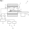
- the magnetic resonance apparatus 10 comprises a magnet unit 11 having a main magnet 12 for generating a strong and, in particular, temporally constant main magnetic field 13.
- the magnetic resonance apparatus 10 comprises a patient receiving area 14 for receiving a patient 15.
- the patient receiving area 14 in the present exemplary embodiment is cylindrical and is surrounded in a circumferential direction by the magnet unit 11. In principle, however, a different design of the patient receiving area 14 is conceivable at any time.
- the patient 15 can be pushed into the patient receiving area 14 by means of a patient support device 16 of the magnetic resonance apparatus 10.
- the patient support device 16 has a patient table 17 which is designed to be movable within the patient receiving area 14.
- the magnet unit 11 further comprises a gradient coil unit 18 for generating magnetic field gradients used for spatial encoding during imaging.
- the gradient coil unit 18 is controlled by a gradient control unit 19 of the magnetic resonance device 10.
- the magnet unit 11 further comprises a radio-frequency antenna unit 20, which in the present exemplary embodiment is designed as a body coil permanently integrated into the magnetic resonance device 10.
- the radio-frequency antenna unit 20 is designed to excite atomic nuclei that arise in the main magnetic field 13 generated by the main magnet 12.
- the radio-frequency antenna unit 20 is controlled by a radio-frequency antenna control unit 21 of the magnetic resonance device 10 and radiates radio-frequency magnetic resonance sequences into an examination room, which is essentially formed by a patient receiving area 14 of the magnetic resonance device 10.
- the radio frequency antenna unit 20 is further designed to receive magnetic resonance signals.
- the magnetic resonance apparatus 10 has a system control unit 22 for controlling the main magnet 12, the gradient control unit 19, and the radio-frequency antenna control unit 21.
- the system control unit 22 centrally controls the magnetic resonance apparatus 10, such as performing a predetermined imaging gradient echo sequence.
- the magnetic resonance device 10 comprises a flexible MR local coil 100, which is arranged directly on the patient 15.
- the MR local coil 100 comprises at least one magnetic resonance antenna and is designed to receive magnetic resonance signals with the at least one magnetic resonance antenna.
- 20 is also configured to transmit high-frequency magnetic resonance sequences. The received magnetic resonance signals are transmitted to the high-frequency antenna control unit 21.
- the system control unit 22 comprises an evaluation unit (not shown in detail) for evaluating the magnetic resonance signals acquired during the magnetic resonance examination.
- the magnetic resonance device 10 comprises a user interface 23 connected to the system control unit 22. Control information such as imaging parameters and reconstructed magnetic resonance images can be displayed on a display unit 24, for example, on at least one monitor, of the user interface 23 for medical personnel.
- the user interface 23 has an input unit 25, by means of which information and/or parameters can be entered by the medical personnel during a measurement process.
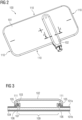
- Fig. 2 shows an exemplary MR local coil 100 with an outer shell 101 and a cover 102.
- the outer shell 101 comprises, for example, an artificial leather and/or a PU-coated fabric or consists thereof.
- the cross-section indicated here, section AA, is in Fig. 3 shown.
- the outer shell 101 has a flat upper side 101a and an opposite flat lower side 101b. Between them lies an inner space of the outer shell or the MR local coil. At four Fig. 2 The top side 101a is connected to the bottom side 101b on the end faces shown.
- the MR local coil comprises a frame 103, which is firmly connected to the upper side 101a of the outer shell 101 at the surfaces 111, and an antenna structure 104, which comprises at least one MR antenna and is arranged in the interior of the outer shell.
- the connection at the surfaces 111 can be established, for example, by ultrasonic welding. so that the frame 103 is connected to the outer shell 101 by means of an ultrasonic weld
- the frame 103 is configured to receive the antenna structure 104 and hold it in position.
- the frame comprises a guide structure 107
- the antenna structure 104 comprises a corresponding counterstructure 106.
- the guide structure 107 here in the form of a tongue
- the counterstructure 106 here in the form of a tongue
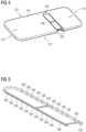
- the frame 103 is in the Figs. 4 and 5 shown in more detail. During the manufacturing process, it initially includes predetermined breaking points 108, which are then broken during the manufacturing process, resulting in multiple breaking points. Thus, the frame 103 is rigid in some areas between the breaking points.
- the frame 103 shown has two transverse webs. These can advantageously stiffen the frame 103, allowing it to be handled more easily during the manufacture of the MR local coil 100, particularly during welding of the frame 103 to the outer shell 101.
- the two transverse webs have further predetermined breaking points at their ends, i.e., at the transition to the rest of the frame. By breaking the frame 103 at these predetermined breaking points, the transverse webs can be easily removed, creating a particularly large opening for inserting the antenna structure 104.
- the outer shell 101 has an opening 109 on one of the multiple end faces 101 for inserting the antenna structure 104 into the interior of the outer shell 101.
- the frame 103 is adjacent to the opening 109.
- the end faces 110 a uniform outer seam all the way around.
- the outer seam can, for example, be an ultrasonic weld.
- Fig. 2 and 3 The cover 102 shown is detachably attached to the outer shell in the area of the frame 103.
- the frame 103 is clamped by the cover 102.
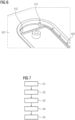
- Fig. 7 shows a flowchart of a method for an MR local coil.
- the outer shell 101 including various lining materials, is produced in S1 by ultrasonic welding. This creates a completely closed outer seam in the visible area of the MR local coil or an outer seam that is only interrupted in the area of the housing cover, see Fig. 4 It is also conceivable to carry out step S1 later in the manufacturing process, e.g. only after S2.
- the outer shell 101 including various lining materials and/or cushioning layers and/or sliding layers, is welded to the frame 103 by ultrasonic welding in step S2, thereby firmly bonding the various materials to the frame.
- the frame 103 is designed to provide as much surface area as necessary for the welding process while being as delicate as possible.
- the frame 103 is broken into several individual parts at its predetermined breaking points in the welded state in S3.
- any stabilizing crossbars of the frame 103 can be removed. This creates a flexible, defined opening to the interior of the outer shell 101, despite its partially rigid design.
- the prepared antenna structure 104 is threaded along the break points into the outer shell 101 in S4.
- the threaded antenna structure 104 contains counterparts 106 and 112, which rest against the defined broken frame 103, see Fig. 3 or Fig. 6 .
- the cover 102 is screwed on in S5, thereby clamping the controlled-break frame 103 in a defined manner.
- the frame 103 thus ensures that the outer shell 101 cannot slip out of the clamp.
- the proposed MR local coil 100 advantageously does not require an additional opening for inserting the antenna structure 104 into the outer shell 101, which would subsequently have to be closed again in a further step, for example, by ultrasonic welding or gluing.
- a further advantage can be that the final product has a uniform outer seam and, in particular, no transition in the seam is required, especially at a transition from an inner seam to an outer seam, and is therefore not visible from the outside.
- such a seam is advantageously more robust than a split outer seam, since a closing seam would have to perfectly match the remaining outer seam.
- the uniform outer seam lends the product a more valuable appearance and eliminates an additional work step.
- the MR local coil 100, the magnetic resonance device 10 and the method described in detail above are merely exemplary embodiments which can be modified in a variety of ways by a person skilled in the art. without departing from the scope of the invention.
- the use of the indefinite articles “a” or “an” does not exclude the possibility that the features in question may be present multiple times.
- the term “unit” does not exclude the possibility that the components in question may consist of several interacting subcomponents, which may also be spatially distributed.
Landscapes
- Physics & Mathematics (AREA)
- Health & Medical Sciences (AREA)
- Condensed Matter Physics & Semiconductors (AREA)
- General Physics & Mathematics (AREA)
- Life Sciences & Earth Sciences (AREA)
- Medical Informatics (AREA)
- Surgery (AREA)
- Engineering & Computer Science (AREA)
- Biomedical Technology (AREA)
- Heart & Thoracic Surgery (AREA)
- Biophysics (AREA)
- Molecular Biology (AREA)
- Pathology (AREA)
- Animal Behavior & Ethology (AREA)
- General Health & Medical Sciences (AREA)
- Public Health (AREA)
- Veterinary Medicine (AREA)
- Nuclear Medicine, Radiotherapy & Molecular Imaging (AREA)
- High Energy & Nuclear Physics (AREA)
- Radiology & Medical Imaging (AREA)
- Magnetic Resonance Imaging Apparatus (AREA)
Claims (15)
- Bobine (100) locale RM comprenant,- une enveloppe (101) extérieure, de constitution souple et entourant un espace intérieur,- un cadre (103) de réception d'une structure (104) d'antenne, de constitution rigide au moins par endroits et relié fixement à l'enveloppe (101) extérieure,- une structure (104) d'antenne ayant au moins une antenne RM, qui est disposée dans l'espace intérieur de l'enveloppe (101) extérieure et qui est maintenue en position par le cadre (103), caractérisée en ce que le cadre (103) a plusieurs points de rupture provenant d'une rupture de points (108) destinés à se rompre.
- Bobine (100) locale RM suivant la revendication 1,
dans laquelle le cadre (103) est relié à l'enveloppe (101) extérieure au moyen d'un cordon de soudure par ultrasons. - Bobine (100) locale RM suivant l'une des revendications précédentes,
dans laquelle l'enveloppe (101) extérieure comprend un cuir artificiel et/ou un tissu revêtu de PU. - Bobine (100) locale RM suivant l'une des revendications précédentes,
dans laquelle l'enveloppe (101) extérieure a une ouverture d'introduction de l'antenne RM dans l'espace intérieur de l'enveloppe extérieure. - Bobine (100) locale RM suivant la revendication 4,
dans laquelle le cadre (103) est contigu à l'ouverture (109). - Bobine (100) locale RM suivant la revendication 4 ou 5, dans laquelle l'enveloppe (101) extérieure a un côté (101a) supérieur plat,dans laquelle l'enveloppe (101) extérieure a un côté (101b) inférieur plat opposé au côté (101a) supérieur,dans laquelle le côté (101a) supérieur et le côté (101b) inférieur sont reliés par plusieurs côtés frontaux,dans laquelle l'ouverture (109) est ménagée sur l'un des plusieurs côtés frontaux.
- Bobine (100) locale RM suivant l'une des revendications 4 à 6,
dans laquelle les plusieurs côtés frontaux ont un cordon extérieur unitaire faisant le tour. - Bobine (100) locale RM suivant la revendication 7,
dans laquelle le cordon extérieur est un cordon de soudure par ultrasons. - Bobine (100) locale RM suivant l'une des revendications précédentes,
dans laquelle le cadre (103) a une structure (107) de guidage, qui coopère avec une structure (106) antagoniste de la structure (104) d'antenne, de manière à maintenir la structure (104) d'antenne en position dans l'espace intérieur de l'enveloppe (101) extérieure. - Bobine (100) locale RM suivant l'une des revendications précédentes,
dans laquelle la structure (104) d'antenne a une rainure et/ou une languette, par laquelle la structure (104) d'antenne est maintenue en position à l'intérieur de l'enveloppe (101) extérieure. - Bobine (100) locale RM suivant l'une des revendications précédentes,
dans laquelle la bobine (100) locale RM comprend un couvercle (102) qui, dans la partie du cadre (103), est fixé de manière amovible à l'enveloppe (101) extérieure. - Bobine (100) locale RM suivant la revendication 11,
dans laquelle le cadre (103) est serré par le couvercle (102). - Dispositif (10) de résonnance magnétique comprenant au moins une bobine locale RM suivant l'une des revendications 1 à 12.
- Procédé de fabrication d'une bobine (100) locale RM comprenant- une enveloppe (101) extérieure, de constitution souple et entourant un espace intérieur,- un cadre (103) de réception d'une structure (104) d'antenne, de constitution rigide au moins par endroits et relié fixement à l'enveloppe (101) extérieure,- une structure (104) d'antenne ayant au moins une antenne RM, qui est disposée dans l'espace intérieur de l'enveloppe (101) extérieure et qui est maintenue en position par le cadre (103), caractériséen ce que l'on rompt le cadre en plusieurs points destinés à se rompre, de manière à ce que le cadre ait plusieurs points de rupture, qui s'ensuivent,dans lequel on introduit la structure (104) d'antenne dans l'espace intérieur de l'enveloppe (101) extérieure le long des points de rupture.
- Procédé suivant la revendication 14 de fabrication d'une bobine (100) locale RM suivant l'une des revendications 2 à 12.
Priority Applications (4)
| Application Number | Priority Date | Filing Date | Title |
|---|---|---|---|
| EP20208815.9A EP4001943B1 (fr) | 2020-11-20 | 2020-11-20 | Bobine locale mr et son procédé de fabrication |
| CN202111359110.3A CN114518554B (zh) | 2020-11-20 | 2021-11-17 | 磁共振局部线圈及其制造方法 |
| US17/531,685 US11675032B2 (en) | 2020-11-20 | 2021-11-19 | MR local coil and method for producing same |
| US18/142,332 US12181542B2 (en) | 2020-11-20 | 2023-05-02 | MR local coil and method for producing same |
Applications Claiming Priority (1)
| Application Number | Priority Date | Filing Date | Title |
|---|---|---|---|
| EP20208815.9A EP4001943B1 (fr) | 2020-11-20 | 2020-11-20 | Bobine locale mr et son procédé de fabrication |
Publications (3)
| Publication Number | Publication Date |
|---|---|
| EP4001943A1 EP4001943A1 (fr) | 2022-05-25 |
| EP4001943B1 true EP4001943B1 (fr) | 2025-05-14 |
| EP4001943C0 EP4001943C0 (fr) | 2025-05-14 |
Family
ID=73543060
Family Applications (1)
| Application Number | Title | Priority Date | Filing Date |
|---|---|---|---|
| EP20208815.9A Active EP4001943B1 (fr) | 2020-11-20 | 2020-11-20 | Bobine locale mr et son procédé de fabrication |
Country Status (3)
| Country | Link |
|---|---|
| US (2) | US11675032B2 (fr) |
| EP (1) | EP4001943B1 (fr) |
| CN (1) | CN114518554B (fr) |
Families Citing this family (1)
| Publication number | Priority date | Publication date | Assignee | Title |
|---|---|---|---|---|
| USD1059596S1 (en) * | 2020-10-26 | 2025-01-28 | Siemens Healthineers Ag | Coil for medical imaging apparatus |
Family Cites Families (12)
| Publication number | Priority date | Publication date | Assignee | Title |
|---|---|---|---|---|
| JP3043477B2 (ja) * | 1991-07-17 | 2000-05-22 | 和廣 岡田 | 静電容量の変化を利用したセンサ |
| JP3787752B2 (ja) * | 1999-12-27 | 2006-06-21 | 矢崎総業株式会社 | ワイヤーハーネスの支持構造 |
| US20030070370A1 (en) * | 2001-10-16 | 2003-04-17 | Stibolt Paul E. | Window wrap |
| JP2003116816A (ja) * | 2001-10-18 | 2003-04-22 | Ge Medical Systems Global Technology Co Llc | Rfコイルおよび磁気共鳴撮影装置 |
| JP4345685B2 (ja) * | 2005-02-22 | 2009-10-14 | ヤマハ株式会社 | 物理量センサ、これに使用するリードフレーム、及び、リードフレームの製造方法 |
| CN2815275Y (zh) * | 2005-02-28 | 2006-09-13 | 西门子(中国)有限公司 | 磁共振接收线圈组合结构 |
| EP2992350A1 (fr) * | 2013-05-02 | 2016-03-09 | Koninklijke Philips N.V. | Connecteur amovible et logements de bobine rf divisibles |
| US20170067973A1 (en) * | 2015-09-03 | 2017-03-09 | Samsung Electronics Co., Ltd | Coil assembly and magnetic resonance imaging apparatus including the same |
| KR101821354B1 (ko) * | 2015-09-15 | 2018-01-23 | 삼성전자주식회사 | Rf코일 및 이를 포함하는 자기공명영상장치 |
| DE102018216365A1 (de) | 2018-09-25 | 2020-03-26 | Siemens Healthcare Gmbh | Umhüllung für eine MR-Lokalspule |
| DE202020103535U1 (de) * | 2020-06-19 | 2020-08-20 | Siemens Healthcare Gmbh | Lokalspule mit transparentem Gehäuseteil und Magnetresonanzsystem |
| DE202020104846U1 (de) * | 2020-08-21 | 2020-10-29 | Siemens Healthcare Gmbh | Lokalspule mit Ultraschallschweißnaht |
-
2020
- 2020-11-20 EP EP20208815.9A patent/EP4001943B1/fr active Active
-
2021
- 2021-11-17 CN CN202111359110.3A patent/CN114518554B/zh active Active
- 2021-11-19 US US17/531,685 patent/US11675032B2/en active Active
-
2023
- 2023-05-02 US US18/142,332 patent/US12181542B2/en active Active
Also Published As
| Publication number | Publication date |
|---|---|
| CN114518554A (zh) | 2022-05-20 |
| US20220163609A1 (en) | 2022-05-26 |
| US20230273280A1 (en) | 2023-08-31 |
| CN114518554B (zh) | 2025-09-19 |
| US12181542B2 (en) | 2024-12-31 |
| EP4001943A1 (fr) | 2022-05-25 |
| US11675032B2 (en) | 2023-06-13 |
| EP4001943C0 (fr) | 2025-05-14 |
Similar Documents
| Publication | Publication Date | Title |
|---|---|---|
| DE102008048291B4 (de) | Brustspulenanordnung für Magnetresonanzanwendungen | |
| DE102012209410B4 (de) | Ermittlung einer patientenspezifischen Kontrastmittel-Impulsantwortfunktion sowie darauf basierende Vorhersage eines voraussichtlichen Kontrastmittelverlaufs und Ansteuerung eines medizintechnischen Bildgebungssystems | |
| DE69407848T2 (de) | Magnetanordnung für die Bilderzeugung mittels magnetischer Resonanz | |
| DE102007007099A1 (de) | Medizinische Einrichtung mit wenigstens einem zur Erzeugung von hochintensivem fokussiertem Ultraschall ausgebildeten Wandler und mit einem Magnetresonanzgerät sowie zugehöriger Ultraschallwandler und Verfahren zur Erstellung von Magnetresonanzaufnahmen | |
| EP4001943B1 (fr) | Bobine locale mr et son procédé de fabrication | |
| DE102007009185A1 (de) | Verfahren zur Planung einer angiographischen Messung | |
| DE102014207295B4 (de) | Magnetresonanzeinrichtung mit einer Anzeigevorrichtung | |
| DE10147745A1 (de) | Magnetresonanz-Tomographiegerät mit Lärmunterdrückung durch Dämpfung von mechanischen Schwingungen | |
| DE102009007361B4 (de) | Aufnahme von zeitaufgelösten Magnetresonanzdaten | |
| DE102018216365A1 (de) | Umhüllung für eine MR-Lokalspule | |
| DE102008064106A1 (de) | Verfahren zur Bildaufnahme mit einer Magnetresonanzeinrichtung und Magnetresonanzeinrichtung | |
| DE102010041125B4 (de) | Räumliche Korrektur von Bilddaten einer Serie von Magnetresonanzaufnahmen | |
| DE102009043449A1 (de) | Patientenliege und kombinierte medizinische Untersuchungseinrichtung mit einer Patientenliege | |
| DE102012204134A1 (de) | Verfahren zum automatischen Bestimmen von Bildgebungs-Ebenen und Magnetresonanzanlage | |
| DE202023101763U1 (de) | Flexible Lokalspule für ein Magnetresonanzsystem, sowie Magnetresonanzsystem | |
| DE102017207687B4 (de) | Reduktion von Artefakten durch Kombination von SPAIR-Puls und Sättigungspuls | |
| EP0854367B1 (fr) | Méthode de RM de surveillance assistée par imagerie du déplacement d'un objet et appareil de RM pour l'exécution de la méthode | |
| DE102004033253A1 (de) | Verfahren und Vorrichtung zur automatischen Aufrechterhaltung der Schleifenentkopplung bei positionsveränderlichen MRI-Spulen | |
| DE102019203628B4 (de) | MR-Lokalspule mit verbesserter Kante, entsprechendes Werkzeug und Verfahren zur Herstellung | |
| DE202020104846U1 (de) | Lokalspule mit Ultraschallschweißnaht | |
| DE102005017310B4 (de) | Verfahren zum Erzeugen eines homogenen hochfrequenten Magnetfelds im Inneren einer zylindrischen Körperspule einer Magnetresonanzeinrichtung, sowie Magnetresonanzeinrichtung zur Durchführung des Verfahrens | |
| EP3187889B1 (fr) | Bobine locale adaptable pour irm | |
| DE202020102476U1 (de) | Lokalspule mit Elektronikkomponentengehäuse | |
| DE102010040402B4 (de) | Vereinfachte Definition von gekrümmten Anregungen in der parallelen MR-Bildgebung | |
| EP1783508B1 (fr) | Object à tester pour un appareil à résonance magnétique nucléaire |
Legal Events
| Date | Code | Title | Description |
|---|---|---|---|
| PUAI | Public reference made under article 153(3) epc to a published international application that has entered the european phase |
Free format text: ORIGINAL CODE: 0009012 |
|
| STAA | Information on the status of an ep patent application or granted ep patent |
Free format text: STATUS: THE APPLICATION HAS BEEN PUBLISHED |
|
| AK | Designated contracting states |
Kind code of ref document: A1 Designated state(s): AL AT BE BG CH CY CZ DE DK EE ES FI FR GB GR HR HU IE IS IT LI LT LU LV MC MK MT NL NO PL PT RO RS SE SI SK SM TR |
|
| STAA | Information on the status of an ep patent application or granted ep patent |
Free format text: STATUS: REQUEST FOR EXAMINATION WAS MADE |
|
| 17P | Request for examination filed |
Effective date: 20221118 |
|
| RBV | Designated contracting states (corrected) |
Designated state(s): AL AT BE BG CH CY CZ DE DK EE ES FI FR GB GR HR HU IE IS IT LI LT LU LV MC MK MT NL NO PL PT RO RS SE SI SK SM TR |
|
| RAP1 | Party data changed (applicant data changed or rights of an application transferred) |
Owner name: SIEMENS HEALTHINEERS AG |
|
| GRAP | Despatch of communication of intention to grant a patent |
Free format text: ORIGINAL CODE: EPIDOSNIGR1 |
|
| STAA | Information on the status of an ep patent application or granted ep patent |
Free format text: STATUS: GRANT OF PATENT IS INTENDED |
|
| RIC1 | Information provided on ipc code assigned before grant |
Ipc: G01R 33/341 20060101ALN20241230BHEP Ipc: A61B 5/00 20060101ALI20241230BHEP Ipc: A61B 5/055 20060101ALI20241230BHEP Ipc: G01R 33/34 20060101AFI20241230BHEP |
|
| RIC1 | Information provided on ipc code assigned before grant |
Ipc: G01R 33/341 20060101ALN20250106BHEP Ipc: A61B 5/00 20060101ALI20250106BHEP Ipc: A61B 5/055 20060101ALI20250106BHEP Ipc: G01R 33/34 20060101AFI20250106BHEP |
|
| INTG | Intention to grant announced |
Effective date: 20250121 |
|
| GRAS | Grant fee paid |
Free format text: ORIGINAL CODE: EPIDOSNIGR3 |
|
| GRAA | (expected) grant |
Free format text: ORIGINAL CODE: 0009210 |
|
| STAA | Information on the status of an ep patent application or granted ep patent |
Free format text: STATUS: THE PATENT HAS BEEN GRANTED |
|
| AK | Designated contracting states |
Kind code of ref document: B1 Designated state(s): AL AT BE BG CH CY CZ DE DK EE ES FI FR GB GR HR HU IE IS IT LI LT LU LV MC MK MT NL NO PL PT RO RS SE SI SK SM TR |
|
| REG | Reference to a national code |
Ref country code: GB Ref legal event code: FG4D Free format text: NOT ENGLISH |
|
| REG | Reference to a national code |
Ref country code: CH Ref legal event code: EP |
|
| REG | Reference to a national code |
Ref country code: IE Ref legal event code: FG4D Free format text: LANGUAGE OF EP DOCUMENT: GERMAN |
|
| REG | Reference to a national code |
Ref country code: DE Ref legal event code: R096 Ref document number: 502020011047 Country of ref document: DE |
|
| U01 | Request for unitary effect filed |
Effective date: 20250521 |
|
| U07 | Unitary effect registered |
Designated state(s): AT BE BG DE DK EE FI FR IT LT LU LV MT NL PT RO SE SI Effective date: 20250530 |
|
| PG25 | Lapsed in a contracting state [announced via postgrant information from national office to epo] |
Ref country code: ES Free format text: LAPSE BECAUSE OF FAILURE TO SUBMIT A TRANSLATION OF THE DESCRIPTION OR TO PAY THE FEE WITHIN THE PRESCRIBED TIME-LIMIT Effective date: 20250514 |
|
| PG25 | Lapsed in a contracting state [announced via postgrant information from national office to epo] |
Ref country code: GR Free format text: LAPSE BECAUSE OF FAILURE TO SUBMIT A TRANSLATION OF THE DESCRIPTION OR TO PAY THE FEE WITHIN THE PRESCRIBED TIME-LIMIT Effective date: 20250815 Ref country code: NO Free format text: LAPSE BECAUSE OF FAILURE TO SUBMIT A TRANSLATION OF THE DESCRIPTION OR TO PAY THE FEE WITHIN THE PRESCRIBED TIME-LIMIT Effective date: 20250814 |
|
| PG25 | Lapsed in a contracting state [announced via postgrant information from national office to epo] |
Ref country code: PL Free format text: LAPSE BECAUSE OF FAILURE TO SUBMIT A TRANSLATION OF THE DESCRIPTION OR TO PAY THE FEE WITHIN THE PRESCRIBED TIME-LIMIT Effective date: 20250514 |
|
| PG25 | Lapsed in a contracting state [announced via postgrant information from national office to epo] |
Ref country code: HR Free format text: LAPSE BECAUSE OF FAILURE TO SUBMIT A TRANSLATION OF THE DESCRIPTION OR TO PAY THE FEE WITHIN THE PRESCRIBED TIME-LIMIT Effective date: 20250514 |
|
| PG25 | Lapsed in a contracting state [announced via postgrant information from national office to epo] |
Ref country code: RS Free format text: LAPSE BECAUSE OF FAILURE TO SUBMIT A TRANSLATION OF THE DESCRIPTION OR TO PAY THE FEE WITHIN THE PRESCRIBED TIME-LIMIT Effective date: 20250814 |
|
| PG25 | Lapsed in a contracting state [announced via postgrant information from national office to epo] |
Ref country code: IS Free format text: LAPSE BECAUSE OF FAILURE TO SUBMIT A TRANSLATION OF THE DESCRIPTION OR TO PAY THE FEE WITHIN THE PRESCRIBED TIME-LIMIT Effective date: 20250914 |
|
| U20 | Renewal fee for the european patent with unitary effect paid |
Year of fee payment: 6 Effective date: 20251120 |
|
| PGFP | Annual fee paid to national office [announced via postgrant information from national office to epo] |
Ref country code: GB Payment date: 20251211 Year of fee payment: 6 |
|
| PG25 | Lapsed in a contracting state [announced via postgrant information from national office to epo] |
Ref country code: SM Free format text: LAPSE BECAUSE OF FAILURE TO SUBMIT A TRANSLATION OF THE DESCRIPTION OR TO PAY THE FEE WITHIN THE PRESCRIBED TIME-LIMIT Effective date: 20250514 |
|
| PG25 | Lapsed in a contracting state [announced via postgrant information from national office to epo] |
Ref country code: CZ Free format text: LAPSE BECAUSE OF FAILURE TO SUBMIT A TRANSLATION OF THE DESCRIPTION OR TO PAY THE FEE WITHIN THE PRESCRIBED TIME-LIMIT Effective date: 20250514 |
|
| PG25 | Lapsed in a contracting state [announced via postgrant information from national office to epo] |
Ref country code: SK Free format text: LAPSE BECAUSE OF FAILURE TO SUBMIT A TRANSLATION OF THE DESCRIPTION OR TO PAY THE FEE WITHIN THE PRESCRIBED TIME-LIMIT Effective date: 20250514 |
|
| PLBE | No opposition filed within time limit |
Free format text: ORIGINAL CODE: 0009261 |
|
| STAA | Information on the status of an ep patent application or granted ep patent |
Free format text: STATUS: NO OPPOSITION FILED WITHIN TIME LIMIT |
|
| REG | Reference to a national code |
Ref country code: CH Ref legal event code: L10 Free format text: ST27 STATUS EVENT CODE: U-0-0-L10-L00 (AS PROVIDED BY THE NATIONAL OFFICE) Effective date: 20260325 |
|
| 26N | No opposition filed |
Effective date: 20260217 |