EP4001954A1 - Procédé de détection radar et radar à modulation numérique résistant au déséquilibre iq - Google Patents
Procédé de détection radar et radar à modulation numérique résistant au déséquilibre iq Download PDFInfo
- Publication number
- EP4001954A1 EP4001954A1 EP20208013.1A EP20208013A EP4001954A1 EP 4001954 A1 EP4001954 A1 EP 4001954A1 EP 20208013 A EP20208013 A EP 20208013A EP 4001954 A1 EP4001954 A1 EP 4001954A1
- Authority
- EP
- European Patent Office
- Prior art keywords
- radar
- code sequence
- integer
- signal
- range
- Prior art date
- Legal status (The legal status is an assumption and is not a legal conclusion. Google has not performed a legal analysis and makes no representation as to the accuracy of the status listed.)
- Granted
Links
Images




Classifications
-
- G—PHYSICS
- G01—MEASURING; TESTING
- G01S—RADIO DIRECTION-FINDING; RADIO NAVIGATION; DETERMINING DISTANCE OR VELOCITY BY USE OF RADIO WAVES; LOCATING OR PRESENCE-DETECTING BY USE OF THE REFLECTION OR RERADIATION OF RADIO WAVES; ANALOGOUS ARRANGEMENTS USING OTHER WAVES
- G01S7/00—Details of systems according to groups G01S13/00, G01S15/00, G01S17/00
- G01S7/02—Details of systems according to groups G01S13/00, G01S15/00, G01S17/00 of systems according to group G01S13/00
- G01S7/35—Details of non-pulse systems
- G01S7/352—Receivers
- G01S7/354—Extracting wanted echo-signals
-
- G—PHYSICS
- G01—MEASURING; TESTING
- G01S—RADIO DIRECTION-FINDING; RADIO NAVIGATION; DETERMINING DISTANCE OR VELOCITY BY USE OF RADIO WAVES; LOCATING OR PRESENCE-DETECTING BY USE OF THE REFLECTION OR RERADIATION OF RADIO WAVES; ANALOGOUS ARRANGEMENTS USING OTHER WAVES
- G01S7/00—Details of systems according to groups G01S13/00, G01S15/00, G01S17/00
- G01S7/02—Details of systems according to groups G01S13/00, G01S15/00, G01S17/00 of systems according to group G01S13/00
- G01S7/03—Details of HF subsystems specially adapted therefor, e.g. common to transmitter and receiver
- G01S7/032—Constructional details for solid-state radar subsystems
-
- G—PHYSICS
- G01—MEASURING; TESTING
- G01S—RADIO DIRECTION-FINDING; RADIO NAVIGATION; DETERMINING DISTANCE OR VELOCITY BY USE OF RADIO WAVES; LOCATING OR PRESENCE-DETECTING BY USE OF THE REFLECTION OR RERADIATION OF RADIO WAVES; ANALOGOUS ARRANGEMENTS USING OTHER WAVES
- G01S7/00—Details of systems according to groups G01S13/00, G01S15/00, G01S17/00
- G01S7/02—Details of systems according to groups G01S13/00, G01S15/00, G01S17/00 of systems according to group G01S13/00
-
- G—PHYSICS
- G01—MEASURING; TESTING
- G01S—RADIO DIRECTION-FINDING; RADIO NAVIGATION; DETERMINING DISTANCE OR VELOCITY BY USE OF RADIO WAVES; LOCATING OR PRESENCE-DETECTING BY USE OF THE REFLECTION OR RERADIATION OF RADIO WAVES; ANALOGOUS ARRANGEMENTS USING OTHER WAVES
- G01S13/00—Systems using the reflection or reradiation of radio waves, e.g. radar systems; Analogous systems using reflection or reradiation of waves whose nature or wavelength is irrelevant or unspecified
- G01S13/02—Systems using reflection of radio waves, e.g. primary radar systems; Analogous systems
- G01S13/06—Systems determining position data of a target
- G01S13/08—Systems for measuring distance only
- G01S13/10—Systems for measuring distance only using transmission of interrupted, pulse modulated waves
- G01S13/26—Systems for measuring distance only using transmission of interrupted, pulse modulated waves wherein the transmitted pulses use a frequency- or phase-modulated carrier wave
- G01S13/28—Systems for measuring distance only using transmission of interrupted, pulse modulated waves wherein the transmitted pulses use a frequency- or phase-modulated carrier wave with time compression of received pulses
- G01S13/284—Systems for measuring distance only using transmission of interrupted, pulse modulated waves wherein the transmitted pulses use a frequency- or phase-modulated carrier wave with time compression of received pulses using coded pulses
- G01S13/288—Systems for measuring distance only using transmission of interrupted, pulse modulated waves wherein the transmitted pulses use a frequency- or phase-modulated carrier wave with time compression of received pulses using coded pulses phase modulated
-
- G—PHYSICS
- G01—MEASURING; TESTING
- G01S—RADIO DIRECTION-FINDING; RADIO NAVIGATION; DETERMINING DISTANCE OR VELOCITY BY USE OF RADIO WAVES; LOCATING OR PRESENCE-DETECTING BY USE OF THE REFLECTION OR RERADIATION OF RADIO WAVES; ANALOGOUS ARRANGEMENTS USING OTHER WAVES
- G01S13/00—Systems using the reflection or reradiation of radio waves, e.g. radar systems; Analogous systems using reflection or reradiation of waves whose nature or wavelength is irrelevant or unspecified
- G01S13/02—Systems using reflection of radio waves, e.g. primary radar systems; Analogous systems
- G01S13/06—Systems determining position data of a target
- G01S13/08—Systems for measuring distance only
- G01S13/32—Systems for measuring distance only using transmission of continuous waves, whether amplitude-, frequency-, or phase-modulated, or unmodulated
- G01S13/325—Systems for measuring distance only using transmission of continuous waves, whether amplitude-, frequency-, or phase-modulated, or unmodulated using transmission of coded signals, e.g. P.S.K. signals
-
- G—PHYSICS
- G01—MEASURING; TESTING
- G01S—RADIO DIRECTION-FINDING; RADIO NAVIGATION; DETERMINING DISTANCE OR VELOCITY BY USE OF RADIO WAVES; LOCATING OR PRESENCE-DETECTING BY USE OF THE REFLECTION OR RERADIATION OF RADIO WAVES; ANALOGOUS ARRANGEMENTS USING OTHER WAVES
- G01S13/00—Systems using the reflection or reradiation of radio waves, e.g. radar systems; Analogous systems using reflection or reradiation of waves whose nature or wavelength is irrelevant or unspecified
- G01S13/02—Systems using reflection of radio waves, e.g. primary radar systems; Analogous systems
- G01S13/50—Systems of measurement based on relative movement of target
- G01S13/58—Velocity or trajectory determination systems; Sense-of-movement determination systems
-
- G—PHYSICS
- G01—MEASURING; TESTING
- G01S—RADIO DIRECTION-FINDING; RADIO NAVIGATION; DETERMINING DISTANCE OR VELOCITY BY USE OF RADIO WAVES; LOCATING OR PRESENCE-DETECTING BY USE OF THE REFLECTION OR RERADIATION OF RADIO WAVES; ANALOGOUS ARRANGEMENTS USING OTHER WAVES
- G01S13/00—Systems using the reflection or reradiation of radio waves, e.g. radar systems; Analogous systems using reflection or reradiation of waves whose nature or wavelength is irrelevant or unspecified
- G01S13/02—Systems using reflection of radio waves, e.g. primary radar systems; Analogous systems
- G01S13/50—Systems of measurement based on relative movement of target
- G01S13/58—Velocity or trajectory determination systems; Sense-of-movement determination systems
- G01S13/581—Velocity or trajectory determination systems; Sense-of-movement determination systems using transmission of interrupted pulse modulated waves and based upon the Doppler effect resulting from movement of targets
- G01S13/582—Velocity or trajectory determination systems; Sense-of-movement determination systems using transmission of interrupted pulse modulated waves and based upon the Doppler effect resulting from movement of targets adapted for simultaneous range and velocity measurements
-
- G—PHYSICS
- G01—MEASURING; TESTING
- G01S—RADIO DIRECTION-FINDING; RADIO NAVIGATION; DETERMINING DISTANCE OR VELOCITY BY USE OF RADIO WAVES; LOCATING OR PRESENCE-DETECTING BY USE OF THE REFLECTION OR RERADIATION OF RADIO WAVES; ANALOGOUS ARRANGEMENTS USING OTHER WAVES
- G01S13/00—Systems using the reflection or reradiation of radio waves, e.g. radar systems; Analogous systems using reflection or reradiation of waves whose nature or wavelength is irrelevant or unspecified
- G01S13/02—Systems using reflection of radio waves, e.g. primary radar systems; Analogous systems
- G01S13/50—Systems of measurement based on relative movement of target
- G01S13/58—Velocity or trajectory determination systems; Sense-of-movement determination systems
- G01S13/583—Velocity or trajectory determination systems; Sense-of-movement determination systems using transmission of continuous unmodulated waves, amplitude-, frequency-, or phase-modulated waves and based upon the Doppler effect resulting from movement of targets
- G01S13/584—Velocity or trajectory determination systems; Sense-of-movement determination systems using transmission of continuous unmodulated waves, amplitude-, frequency-, or phase-modulated waves and based upon the Doppler effect resulting from movement of targets adapted for simultaneous range and velocity measurements
-
- G—PHYSICS
- G01—MEASURING; TESTING
- G01S—RADIO DIRECTION-FINDING; RADIO NAVIGATION; DETERMINING DISTANCE OR VELOCITY BY USE OF RADIO WAVES; LOCATING OR PRESENCE-DETECTING BY USE OF THE REFLECTION OR RERADIATION OF RADIO WAVES; ANALOGOUS ARRANGEMENTS USING OTHER WAVES
- G01S7/00—Details of systems according to groups G01S13/00, G01S15/00, G01S17/00
- G01S7/02—Details of systems according to groups G01S13/00, G01S15/00, G01S17/00 of systems according to group G01S13/00
- G01S7/023—Interference mitigation, e.g. reducing or avoiding non-intentional interference with other HF-transmitters, base station transmitters for mobile communication or other radar systems, e.g. using electro-magnetic interference [EMI] reduction techniques
-
- G—PHYSICS
- G01—MEASURING; TESTING
- G01S—RADIO DIRECTION-FINDING; RADIO NAVIGATION; DETERMINING DISTANCE OR VELOCITY BY USE OF RADIO WAVES; LOCATING OR PRESENCE-DETECTING BY USE OF THE REFLECTION OR RERADIATION OF RADIO WAVES; ANALOGOUS ARRANGEMENTS USING OTHER WAVES
- G01S7/00—Details of systems according to groups G01S13/00, G01S15/00, G01S17/00
- G01S7/02—Details of systems according to groups G01S13/00, G01S15/00, G01S17/00 of systems according to group G01S13/00
- G01S7/28—Details of pulse systems
- G01S7/285—Receivers
- G01S7/288—Coherent receivers
- G01S7/2886—Coherent receivers using I/Q processing
-
- G—PHYSICS
- G01—MEASURING; TESTING
- G01S—RADIO DIRECTION-FINDING; RADIO NAVIGATION; DETERMINING DISTANCE OR VELOCITY BY USE OF RADIO WAVES; LOCATING OR PRESENCE-DETECTING BY USE OF THE REFLECTION OR RERADIATION OF RADIO WAVES; ANALOGOUS ARRANGEMENTS USING OTHER WAVES
- G01S7/00—Details of systems according to groups G01S13/00, G01S15/00, G01S17/00
- G01S7/02—Details of systems according to groups G01S13/00, G01S15/00, G01S17/00 of systems according to group G01S13/00
- G01S7/35—Details of non-pulse systems
- G01S7/352—Receivers
- G01S7/358—Receivers using I/Q processing
Definitions
- the invention relates to radar signal generation and reception, especially in digitally modulated radars, in order to facilitate radar operation robust to non-idealities associated with radar transceivers.
- Digitally modulated radars are now becoming prominent due to their inherit capability of being programmed for different applications and their ability to perform subsequent processing by digital signal processing techniques.
- the data is generally referred to complex data values, with real and imaginary constituents typically termed as In-phase (I) and Quadrature (Q) components, respectively.
- I and Q In-phase
- Q Quadrature
- Signal path characteristics such as gain and phase to the point where I and Q signal components become digital data require a very high degree of balance in order to maintain signal integrity.
- any mismatch between I and Q signal components will allow artifacts to be generated, e.g. time or range sidelobes in radar range profiles and/or in radar range-Doppler maps or ghosts in radar range-Doppler maps, and therefore degrades the radar's performance.
- additional front-end non-linearity especially power amplitude non-linearity from transmitter power amplifier, may introduce along the signal path, which may also produce such undesired artifacts and further degrades the overall performance.
- EP 3 627 787 A1 presents a radar detection technique that is robust to IQ imbalance.
- EP 3 627 787 A1 discloses the generation of an OFDM radar signal based on Hadamard transform that is robust to IQ imbalance.
- the OFDM radar signal of EP 3 627 787 A1 is superior to any OFDM radar in terms of transmitter power amplifier non-linearity robustness, the presented technique is only limited to OFDM radars and cannot be implemented for, e.g. a phase modulated continuous wave (PMCW) radar.
- PMCW phase modulated continuous wave
- an object of the invention is to provide a method and a digitally modulated radar for facilitating radar detection robust to conventional front-end non-idealities, which can be implemented for all digitally modulated radars in general.
- the object is solved by the features of the first independent claim for the method and by the features of the second independent claim for the digitally modulated radar.
- the dependent claims contain further developments.
- the invention proposes a simplified technique to generate radar signals that is robust to front-end non-idealities.
- the invention further proposes a simplified processing of radar detections from said radar signals, where said signal generation and said signal processing are not limited to the type of code sequence, i.e. not limited to the type of modulation scheme used in a digitally modulated radar.
- the constraints that have to be maintained are only limited to the factors such as code sequence length Lc, and to the variables such as K and M, which can be defined or selected irrespective of the type of code sequence and/or modulation scheme.
- the method further comprises the step of correlating the process input signal with respect to the code sequence in order to generate a succession of range profiles.
- the method further comprises the step of accumulating a number of M consecutive range profiles.
- the radar signal preferably comprises periodic repetitions of the code sequence and the reflection signal generally comprises a linear combination of delayed version of the code sequence. This delay is proportional to the target range location.
- the reflection signal is correlated with the transmitted code sequence (or the complex conjugate of the transmitted code sequence), which produces a range profile. Said range profile contains a peak at the location of each target, which is proportional to the power reflected back from said targets.
- the accumulation of multiple consecutive range profiles e.g. a number of M range profiles
- the method further comprises the step of defining Lc with respect to the maximum unambiguous range of the radar for a given radar bandwidth, where the maximum unambiguous range of the radar is given by its ability to receive the reflected pulse or chip completely before the next transmitting pulse or chip.
- the radar bandwidth is preferably defined based on a preferred range resolution, i.e. the measurement of smallest distance of separation of its targets.
- the method further comprises the step of generating the radar signal comprising a number of N periodic repetitions of the number of M periodic repetitions of the code sequence, where N is an integer.
- the method further comprises the step of processing a number of N range profiles in order to produce a range-Doppler map.
- the number of repetitions N define the number of samples used for Doppler processing in order to estimate the target velocity.
- the code sequence corresponds to a binary code sequence or a real code sequence or a complex code sequence.
- the invention further proposes a modulation specific (BPSK) implementation of the inventive method in order to address additional non-idealities of the front-end in addition to the IQ imbalance.
- BPSK modulation specific
- the invention additionally addresses the power amplitude non-linearity and further proposes radar signal generation and processing scheme that is robust to said non-linearity.
- Said power amplitude non-linearity especially results from non-linear distortions introduced in the transmitter power amplifier, and further introduces unwanted artifacts, e.g. range sidelobes in the range profiles and/or in the range-Doppler maps or ghosts in the range-Doppler maps.
- a digitally modulated radar for facilitating radar detection robust to IQ imbalance.
- the digitally modulated radar comprises a code generation unit configured to generate a radar signal in digital domain comprising a number of M periodic repetitions of a code sequence with a length Lc, multiplied with a progressive phase rotation e j . ⁇ K . n , where Lc and M are integers, K is an integer or a non-integer, and n is a discrete integer variable, i.e. discrete time index corresponding to the code rate.
- the digitally modulated radar further comprises a processing unit configured to generate a process input signal in digital domain from a reflection signal corresponding to the radar signal by multiplying the reflection signal with a progressive phase rotation e ⁇ j . ⁇ K . n .
- the code generation unit is further configured to define K such that a ratio Lc K is a non-integer.
- the code generation unit is further configured to define M such that a ratio Lc . M K is an integer.
- the invention proposes a simplified technique to generate radar signals as well as to process radar detections, which is robust to front-end non-idealities and is not limited to the type of code sequence and/or modulation scheme used in a digitally modulated radar.
- the digitally modulated radar further comprises a transmission path configured to transmit the radar signal comprising at least one digital to analog converter, at least one low pass filter, at least one mixer, and at least one power amplifier.
- the digitally modulated radar further comprises a reception path configured to receive the reflection signal comprising at least one low noise amplifier, at least one mixer, at least one low pass filter, and at least one analog to digital converter.
- the transmission path is configured to convey I and Q signal components with their respective domain conversion and successive filtration.
- the reception path is configured to convey I and Q signal components with their respective filtration and successive domain conversion.
- the processing unit is further configured to correlate the process input signal with respect to the code sequence in order to generate a succession of range profiles.
- the processing unit is further configured to accumulate a number of M consecutive range profiles.
- the accumulation of multiple consecutive range profiles improves the signal-to-noise ratio, for example.
- the code sequence corresponds to a binary code sequence or a real code sequence or a complex code sequence.
- the invention further proposes a modulation specific (BPSK) implementation in order to address additional non-idealities of the front-end in addition to the IQ imbalance.
- BPSK modulation specific
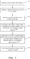
- a code sequence with a code sequence length Lc is selected.
- a value for a parameter K is selected such that a ratio Lc/K is a non-integer.
- a value for a parameter M is selected such that a ratio Lc.M/K is an integer.
- a radar signal is generated in digital domain by multiplying M periodic repetitions of the code sequence with a progressive phase rotation e j . ⁇ K . n .
- a process input signal is generated in digital domain from a reflection signal corresponding to the radar signal by multiplying the reflection signal with a progressive phase rotation e ⁇ j . ⁇ K . n .
- range processing is performed with the process input signal.
- the range processing comprises the generation of range profiles, Doppler profiles, and further the combination of said range and Doppler profiles that is referred to as a range-Doppler map.
- the method comprises successive steps of correlating the process input signal with respect to the code sequence in order to generate a succession of range profiles and further accumulating M consecutive range profiles to improve SNR.
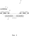
- Fig. 2 an exemplary transmission frame 200 for the acquisition of one radar data cube is illustrated.
- the transmission frame 200 is shown as a conventional transmission frame for a single-input-single-output phase modulated continuous wave (SISO-PMCW) radar.
- the code sequence length Lc defines the number samples or chips 201 in the code sequence 202, as denoted herein as "s".
- the code sequence length Lc defines the number of range bins for the range processing operation.
- the so-called pulse repetition frequency for a digitally modulated radar can be defined as the sequence of length Lc repeating itself with a chip rate fc, for example.
- the parameter M defines the number of repetitions 203 of the same code sequence "s" that are accumulated, analogous to the conventional pseudorandom code sequences such as the maximum length sequence (MLS). In other words, the number of repetition M defines the number of range profiles to be coherently accumulated.
- the parameter N defines the number of repetition 204 of M sequences 203, i.e. the number of samples for Doppler processing in order to estimate the target velocity. Therefore, the code sequence "s" is repeated M.N times in the transmission frame 200 for the acquisition of one radar data cube.
- the transmission signal is reflected from all targets or obstacles in front of the radar. This produces a linear combination of delayed version of the code sequence "s". This delay is proportional to the target range location.
- the received signal is correlated with the transmitted code sequence "s”, e.g. for binary code sequence, or with the complex conjugate of the transmitted code sequence "s”, e.g. for complex code sequence. This produces a range profile that contains a peak at the location of each target, which is proportional to the power reflected back from said targets.
- Fig. 3A shows an ideal range profile with two targets for M-sequence (MLS).
- the horizontal axis denotes the range of said targets in meters and the vertical axis denotes the reflected power magnitude in decibels.
- the two targets are indicated at the respective peaks with circles 301 and 302.
- Fig. 3B shows an ideal range profile with two targets for almost perfect sequence (APS).
- the horizontal axis denotes the range of said targets in meters and the vertical axis denotes the reflected power magnitude in decibels.
- the two targets are indicated at the respective peaks with circles 303 and 304.
- the output of the correlator should contain zeros in the range bins, which do not correspond to any target.
- some non-null value may appear coming from the code sequence property. Those values are called range sidelobes.
- a M-sequence always produces range sidelobes which are -20log10(Lc) dB below the correlation peak where Lc is the code sequence length, as shown in Fig. 3A .
- an APS does not produce any sidelobes, as shown in Fig. 3B .
- M consecutive range profiles are accumulated to improve the SNR, while the Doppler processing is achieved by Discrete Fourier Transforms (DFT) along the slow time, i.e. N repetitions of M code sequences.
- DFT Discrete Fourier Transforms
- MIMO multi-input multi-output
- sequence "s” depends on the type of digitally modulated radar, such as a phase modulated continuous wave (PMCW) based radar or an orthogonal frequency division modulation (OFDM) based radar.
- PMCW phase modulated continuous wave
- OFDM orthogonal frequency division modulation
- the code sequence selection depends on periodic auto-correlation property of the code sequence as defined in equations (1) and (2). Hence, the code sequences that satisfy the above-mentioned auto-correlation property are selected.
- APS and M-sequences are exemplified in this description, which perfectly satisfies the above-mentioned auto-correlation property.
- APS produces two non-zero values in the range profile instead of only one non-null value and M-sequences give the value 1 instead of 0 when ⁇ 0.
- the range processing is performed with a similar processing as channel equalization in wireless communication. This operation extracts the range profile and removes the code sequence itself. Therefore, every sequence of Lc complex samples can be used and hence, there is no constraint on the value of said complex samples.
- the proposed solution effectively addresses the aforementioned non-idealities and facilitates radar detection robust to said non-idealities, where the proposed solution can be implemented irrespective of the code sequence selection as well as the type of digitally modulated radar.
- a frequency mixer 407 downstream to the LPF 405 modulates the filtered radar signal 406 with a carrier sinewave, preferably generated by a local oscillator (not shown), thereby generating an RF radar signal 408.
- An amplifier, especially a power amplifier (PA) 409 amplifies the RF radar signal 408, thereby generating a radar transmit signal 410, which is transmitted via a transmitter antenna 411. Therefore, the transmission path for transmitting the radar signal 402 composed of the DAC 403, the LPF 405, the frequency mixer 407, the PA 409, and optionally the transmitter antenna 411.
- the radar transmit signal 410 is normally reflected from all targets and the resulting echo or reflected signal or radar receive signal 430 is received by a receiver antenna 431. Generally, only a portion of the transmit signal 410 is reflected back to the receiver antenna 431.
- An amplifier, especially a low noise amplifier (LNA) 429 amplifies the radar receive signal 430, thereby generating an amplified radar receive signal 428.
- a frequency mixer 427 downstream to the LNA 429 demodulates the amplified radar receive signal 428 with the carrier signal generated by the local oscillator, i.e. direct conversion of the amplified radar receive signal 428, thereby generating a baseband signal 426.
- LNA low noise amplifier
- a low pass filter (LPF) 425 downstream to the frequency mixer 427 filters the baseband signal 426, thereby generates a filtered baseband signal 424.
- An analog-to-digital converter (ADC) 423 downstream to the LPF 425 converts the filtered baseband signal 424 into digital domain, thereby generating a reflection signal 422 in digital domain corresponding to the radar signal 402 generated by the code generation unit 401 in digital domain.
- the digitally modulated radar 400 further comprises a processing unit 421 that generates a process input signal in digital domain from the reflection signal 422 in order to perform range and Doppler processing. Therefore, the reception path for receiving the reflection signal 422 composed of the LNA 429, the frequency mixer 427, the LPF 425, the ADC 423, and optionally the receiver antenna 431.
- the transmitter antenna 411 and the receiver antenna 431 can be implemented as dedicated antennas of antenna array for the respective transmission path and the reception path of the digitally modulated radar 400. It is further conceivable that the transmitter antenna 411 and the receiver antenna 431 can be implemented in a single antenna array and the antenna array may be operable in a switching manner, e.g. antenna switching or circulators, for the transmission path and the reception path of the digitally modulated radar 400.
- the code generation unit 401 is further configured to communicate with the processing unit 421, in order to provide information regarding the selected code sequence for correlation.
- the communication signal is shown as a dashed line 412. It is conceivable that the code generation unit 401 and the processing unit 421 can be implemented as a single entity, e.g. as a baseband processing unit.
- additional means for generating and/or processing radar signals e.g. memory or storage for storing code sequences, control commands etc. as well as interfaces such as user interface, are not explicitly shown but are apparent from the above-described implementation.
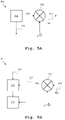
- the code generation unit 401 of Fig. 5A comprises a signal generator 501 that generates chip signals or chips according to a predefined code sequence.
- Such a code sequence may correspond to the transmission frame as shown in Fig. 2 , that comprises a sequence "s" of Lc chips, which is repeated M times, and eventually the M repetition of the "s” is further repeated N times.
- the sequence "s” is repeated M.N time in a single transmission frame.
- the code sequence is shown as b c (n), where n defines a discrete time index that corresponds to the code rate.
- the code sequence b c (n) is repeatedly transmitted as the radar signal, i.e. the repeated code sequence b c (n) is used directly for the successive conversion, filtration and amplification stages.
- the processing unit 421 receives the reflected signal 422, herein shown as u(n), after baseband conversion as described along Fig. 4 .
- the processing unit 421 comprises a multiplier 523 that multiplies the reflected signal u(n) with a progressive phase rotation e ⁇ j . ⁇ K . n .
- This results in the process input signal 524, herein shown as v(n), which is utilized for subsequent processing. Therefore, the process input signal v(n) can be expressed as: v n u n e ⁇ j ⁇ K n
- the multiplier 523 effectively removes the complex exponential.
- the first term b n + ⁇ ⁇ e j ⁇ K ⁇ is a delayed version of the code sequence multiplied by a phase rotation which depends on the propagation delay ⁇ . Therefore, the autocorrelation properties of the code sequence are not affected.
- the second term b n + ⁇ ⁇ e ⁇ j 2 ⁇ n K e ⁇ j ⁇ K ⁇ is also a delayed version of the code sequence multiplied by a phase rotation.
- this term also contains a progressive phase rotation e ⁇ j 2 ⁇ n K .
- This progressive phase rotation breaks the correlation property of the code sequence. This will result in range sidelobes. However, with selection criteria for K, said progressive phase rotation will be mitigated during the radar digital processing chain.
- BPSK modulation An efficient way to implement a low complexity PMCW radar is to use BPSK modulation.
- the modulation signal is only a ⁇ -1; +1 ⁇ code sequence. This results in a binary phase modulated radar.
- the BPSK modulation also shows low Peak-to-Average Power Ratio (PAPR).
- PAPR Peak-to-Average Power Ratio
- the PAPR should be 0 dB (constant magnitude).
- the transition from a +1 to a -1 is not instantaneous and the waveform exhibit a non-constant magnitude which makes the waveform sensitive against non-linear distortions introduced in the power amplifier.
- This PAPR degradation may also come from the pulse shaping operation required to fit with a specific spectrum mask. This phenomenon produces undesired artifacts, called range sidelobes or ghosts, in the range profile.
- the transmission is bandwidth limited, which can be modeled with the LPF 405 with an impulse response h(n).
- the signal is, then, amplified through the PA 409.
- the PA 409 is preferably operated close to its saturation point. However, this produces non-linear distortion in the transmitted signal, which degrade the radar performances.
- the proposed solution implements a different technique, i.e. instead of creating a waveform with low PAPR.
- the proposed technique creates waveform is able to cancel the most significant sources of range sidelobes. For that reason, the following two hypotheses are developed:
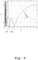
- Fig. 6 magnitudes of z in function of K 600 are illustrated.
- the horizontal axis defines the values for K and the vertical axis defines the magnitude
- the magnitude of z in the function of K 600 reaches to zero.
- zero are 1.5 and 3 at points 601 and 602, respectively. Therefore, values of K such as 3 or 1.5 give no range sidelobes or ghosts while a value 2 for K gives larger range sidelobes and ghosts.
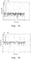
- Fig. 7A shows the range profile with two targets 701, 702 after accumulation, especially for the APS code sequence with a code sequence length 544 for binary phase shift keying (BPSK) modulation.
- the horizontal axis denotes the range of said targets 701, 702 in meters and the vertical axis denotes the reflected power magnitude in decibels.
- the two targets are indicated at the respective peaks 701 and 702 with circles.
- the magnitude of the range sidelobes can be approximated around -60dB.
- Fig. 7B shows the range profile with two targets 701, 702 after accumulation, especially for the APS code sequence with a code sequence length 544 for minimum shift keying (MSK) modulation.
- the horizontal axis denotes the range of said targets 701, 702 in meters and the vertical axis denotes the reflected power magnitude in decibels.
- the two targets are indicated at the respective peaks 701 and 702 with circles.
- the magnitude of the range sidelobes can be approximated around -40dB, i.e. approximately 20db increment in the sidelobe magnitude with respect to the technique of Fig. 7A .
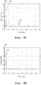
- Fig. 7C shows the range profile with two targets 701, 702 after accumulation, especially for the APS code sequence with a code sequence length 544 for pi/2 binary phase shift keying ( ⁇ /2-BPSK) modulation.
- the horizontal axis denotes the range of said targets 701, 702 in meters and the vertical axis denotes the reflected power magnitude in decibels.
- the two targets are indicated at the respective peaks 701 and 702 with circles.
- the magnitude of the range sidelobes can be approximated around -50dB, i.e. approximately 10db increment in the sidelobe magnitude with respect to the technique of Fig. 7A and approximately 20db decrement in the sidelobe magnitude with respect to the technique of Fig. 7B .
- Fig. 7D shows the range profile with two targets 701, 702 after accumulation, especially for the APS code sequence with a code sequence length 544 according to the proposed solution.
- the value of K is selected as 3
- the value of M is selected as 3
- the horizontal axis denotes the range of said targets 701, 702 in meters and the vertical axis denotes the reflected power magnitude in decibels.
- the two targets are indicated at the respective peaks 701 and 702 with circles.
- the magnitude of the range sidelobes can be approximated around -100dB, which shows superior sidelobe suppression compared to the techniques illustrated along Fig. 7A, Fig. 7B and Fig. 7C , i.e. sidelobe suppression is improved by approximately 40dB, 60dB and 50dB, respectively.
- the range sidelobes at -100dB results from additional taps more than three taps of the low-pass filter as described before. If the low-pass filter only had three taps, no range sidelobes would be observed in the range profile shown in Fig. 7D .
- the proposed solution demonstrates superior performance over the techniques illustrated along Fig. 7A, Fig. 7B and Fig. 7C , since the sidelobes produced by the three most significant taps of the filter are suppressed.
- range profiles for the M-sequence code sequence with a code sequence length of 511 for different modulation techniques are illustrated.
- the range sidelobes come from the limitation of the code sequence itself, as it is known in the art that M-sequence produces ghost targets if they are affected by amplifier non-linearity.
- Fig. 8A shows the range profile with two targets 801, 802 after accumulation, especially for the M-sequence code sequence with a code sequence length 511 for binary phase shift keying (BPSK) modulation.
- the horizontal axis denotes the range of said targets 801, 802 in meters and the vertical axis denotes the reflected power magnitude in decibels.
- the two targets are indicated at the respective peaks 801 and 802 with circles.
- the magnitude of the range sidelobes can be approximated around -50dB. It can be further seen that this technique produces ghost targets as indicated at the peak 803.
- Fig. 8B shows the range profile with two targets 801, 802 after accumulation, especially for the M-sequence code sequence with a code sequence length 511 for minimum shift keying (MSK) modulation.
- the horizontal axis denotes the range of said targets 801, 802 in meters and the vertical axis denotes the reflected power magnitude in decibels.
- the two targets are indicated at the respective peaks 801 and 802 with circles.
- the magnitude of the range sidelobes can be approximated around -55dB.
- Fig. 8C shows the range profile with two targets 801, 802 after accumulation, especially for the M-sequence code sequence with a code sequence length 511 for pi/2 binary phase shift keying ( ⁇ /2-BPSK) modulation.
- the horizontal axis denotes the range of said targets 801, 802 in meters and the vertical axis denotes the reflected power magnitude in decibels.
- the two targets are indicated at the respective peaks 801 and 802 with circles.
- the magnitude of the range sidelobes can be approximated around -55dB, however affected by amplifier non-linearity and produces ghost targets as indicated at the peak 804.
- Fig. 8D shows the range profile with two targets 801, 802 after accumulation, especially for the M-sequence code sequence with a code sequence length 511 according to the proposed solution.
- the value of K is selected as 3
- the value of M is selected as 3
- the horizontal axis denotes the range of said targets 801, 802 in meters and the vertical axis denotes the reflected power magnitude in decibels.
- the two targets are indicated at the respective peaks 801 and 802 with circles.
- the magnitude of the range sidelobes can be approximated around -50dB, and no ghost targets are present, which indicates the robustness to amplifier non-linearity.
- n/2-BPSK and the MSK pulse shaping techniques are robust to IQ imbalance only if M satisfies the proposed criteria of Lc.M/K is an integer. For other values of M, the robustness to IQ imbalance cannot be achieved by said techniques.
- even length code sequence e.g.
- pi/2-BPSK and MSK pulse shaping are very sensitive to IQ mismatch.
- the proposed solution e.g. as exemplified herein as pi/3-BPSK modulation technique, is superior in terms of sidelobe suppression in comparison with the aforesaid techniques for even-length code sequences.
- the proposed solution addresses the problem of sidelobe degradation and ghosts in digitally modulated radars such as PMCW and OFDM radars.
- PMCW and OFDM radars digitally modulated radars
- transceiver non-idealities non-linearity, saturation/clipping, phase noise, IQ imbalance, ADC jitter, and so on
- Range sidelobe degradation translates into a reduced sensitivity and ghost targets translate into false alarms; hence, both must be avoided as much as possible.
- the proposed solution aims at minimizing the effect of power amplifier non-linearity and IQ imbalance.
- a progressive phase rotation is added to the transmitted signal in order to modify the impact of IQ mismatch from one range profile to another. Therefore, with a defined combination of sequence length Lc, number of accumulation M and phase rotation pi/K, it is therefore possible to cancel the range sidelobes coming from IQ mismatch.
- particular phase rotation pi/K strongly improves the robustness to power amplifier non-linearity.
- the embodiments of the present invention can be implemented by hardware, software, or any combination thereof.
- Various embodiments of the present invention may be implemented by one or more application specific integrated circuits (ASICs), digital signal processors (DSPs), digital signal processing devices (DSPDs), programmable logic devices (PLDs), field programmable gate arrays (FPGAs), processors, controllers, microcontrollers, microprocessors, or the like.
- ASICs application specific integrated circuits
- DSPs digital signal processors
- DSPDs digital signal processing devices
- PLDs programmable logic devices
- FPGAs field programmable gate arrays
- processors controllers, microcontrollers, microprocessors, or the like.
Landscapes
- Engineering & Computer Science (AREA)
- Radar, Positioning & Navigation (AREA)
- Remote Sensing (AREA)
- Computer Networks & Wireless Communication (AREA)
- Physics & Mathematics (AREA)
- General Physics & Mathematics (AREA)
- Radar Systems Or Details Thereof (AREA)
Priority Applications (6)
| Application Number | Priority Date | Filing Date | Title |
|---|---|---|---|
| EP20208013.1A EP4001954B1 (fr) | 2020-11-17 | 2020-11-17 | Procédé de détection radar et radar à modulation numérique résistant au déséquilibre iq |
| CN202110829638.6A CN114509728A (zh) | 2020-11-17 | 2021-07-22 | 对iq不平衡稳定的雷达检测方法和数字调制雷达 |
| CN202111349696.5A CN114509724A (zh) | 2020-11-17 | 2021-11-15 | 用于稳健雷达检测的方法以及数字调制雷达 |
| EP21208119.4A EP4001955A1 (fr) | 2020-11-17 | 2021-11-15 | Procédé de détection de radar robuste et radar à modulation numérique |
| US17/526,627 US12111416B2 (en) | 2020-11-17 | 2021-11-15 | Method for robust radar detection and digitally modulated radar |
| US17/527,796 US12025729B2 (en) | 2020-11-17 | 2021-11-16 | Method for radar detection and digitally modulated radar robust to IQ imbalance |
Applications Claiming Priority (1)
| Application Number | Priority Date | Filing Date | Title |
|---|---|---|---|
| EP20208013.1A EP4001954B1 (fr) | 2020-11-17 | 2020-11-17 | Procédé de détection radar et radar à modulation numérique résistant au déséquilibre iq |
Publications (2)
| Publication Number | Publication Date |
|---|---|
| EP4001954A1 true EP4001954A1 (fr) | 2022-05-25 |
| EP4001954B1 EP4001954B1 (fr) | 2025-12-31 |
Family
ID=73455580
Family Applications (2)
| Application Number | Title | Priority Date | Filing Date |
|---|---|---|---|
| EP20208013.1A Active EP4001954B1 (fr) | 2020-11-17 | 2020-11-17 | Procédé de détection radar et radar à modulation numérique résistant au déséquilibre iq |
| EP21208119.4A Pending EP4001955A1 (fr) | 2020-11-17 | 2021-11-15 | Procédé de détection de radar robuste et radar à modulation numérique |
Family Applications After (1)
| Application Number | Title | Priority Date | Filing Date |
|---|---|---|---|
| EP21208119.4A Pending EP4001955A1 (fr) | 2020-11-17 | 2021-11-15 | Procédé de détection de radar robuste et radar à modulation numérique |
Country Status (3)
| Country | Link |
|---|---|
| US (2) | US12111416B2 (fr) |
| EP (2) | EP4001954B1 (fr) |
| CN (2) | CN114509728A (fr) |
Families Citing this family (2)
| Publication number | Priority date | Publication date | Assignee | Title |
|---|---|---|---|---|
| TWI849601B (zh) | 2022-12-01 | 2024-07-21 | 立積電子股份有限公司 | 訊號產生電路、雷達裝置及訊號控制方法 |
| KR102587987B1 (ko) * | 2023-07-21 | 2023-10-11 | 포항공과대학교 산학협력단 | Mpsk-mimo fmcw 레이다에서 각도 추정을 이용한 표적탐지 장치 및 방법 |
Citations (3)
| Publication number | Priority date | Publication date | Assignee | Title |
|---|---|---|---|---|
| US20150341203A1 (en) * | 2014-05-23 | 2015-11-26 | Panasonic Ip Man Co Ltd | Pulse radar device and control method therefor |
| EP3627787A1 (fr) | 2018-09-22 | 2020-03-25 | IMEC vzw | Détection radar à base d'ofdm |
| US20200191940A1 (en) * | 2018-12-18 | 2020-06-18 | Nxp Usa, Inc. | Extended doppler pmcw code division mimo radar |
Family Cites Families (6)
| Publication number | Priority date | Publication date | Assignee | Title |
|---|---|---|---|---|
| CN101706583B (zh) * | 2009-10-16 | 2012-07-04 | 西安交通大学 | 一种多偏移距vsp成像的局域化相空间方法 |
| WO2015085120A1 (fr) * | 2013-12-06 | 2015-06-11 | Lynch Jonathan J | Procédés et appareils de traitement de signaux de radar à synthèse d'ouverture (rso) |
| JP6566396B2 (ja) * | 2015-08-06 | 2019-08-28 | パナソニック株式会社 | レーダ装置 |
| JP6818541B2 (ja) * | 2016-03-14 | 2021-01-20 | パナソニック株式会社 | レーダ装置および測位方法 |
| LU100243B1 (en) * | 2017-05-10 | 2018-11-26 | Iee Sa | Orthogonal Phase Modulation for Detection and Communication in Radar |
| CN111880171B (zh) * | 2020-07-07 | 2023-09-05 | 西安电子科技大学 | 一种消除雷达目标盲速的脉冲分段编码方法 |
-
2020
- 2020-11-17 EP EP20208013.1A patent/EP4001954B1/fr active Active
-
2021
- 2021-07-22 CN CN202110829638.6A patent/CN114509728A/zh active Pending
- 2021-11-15 CN CN202111349696.5A patent/CN114509724A/zh active Pending
- 2021-11-15 US US17/526,627 patent/US12111416B2/en active Active
- 2021-11-15 EP EP21208119.4A patent/EP4001955A1/fr active Pending
- 2021-11-16 US US17/527,796 patent/US12025729B2/en active Active
Patent Citations (3)
| Publication number | Priority date | Publication date | Assignee | Title |
|---|---|---|---|---|
| US20150341203A1 (en) * | 2014-05-23 | 2015-11-26 | Panasonic Ip Man Co Ltd | Pulse radar device and control method therefor |
| EP3627787A1 (fr) | 2018-09-22 | 2020-03-25 | IMEC vzw | Détection radar à base d'ofdm |
| US20200191940A1 (en) * | 2018-12-18 | 2020-06-18 | Nxp Usa, Inc. | Extended doppler pmcw code division mimo radar |
Also Published As
| Publication number | Publication date |
|---|---|
| US20220155433A1 (en) | 2022-05-19 |
| US12025729B2 (en) | 2024-07-02 |
| US12111416B2 (en) | 2024-10-08 |
| US20220155412A1 (en) | 2022-05-19 |
| EP4001954B1 (fr) | 2025-12-31 |
| CN114509724A (zh) | 2022-05-17 |
| CN114509728A (zh) | 2022-05-17 |
| EP4001955A1 (fr) | 2022-05-25 |
Similar Documents
| Publication | Publication Date | Title |
|---|---|---|
| US9075138B2 (en) | Efficient pulse Doppler radar with no blind ranges, range ambiguities, blind speeds, or Doppler ambiguities | |
| US7068715B2 (en) | Ultra-wideband communications system and method using a delay hopped, continuous noise transmitted reference | |
| JP2004535562A (ja) | 妨害信号を検出したときパルスごとに周波数スペクトルの間隔を不規則に変化させるパルスレーダ | |
| JP6340689B2 (ja) | パルスレーダ装置、およびパルスレーダ装置の制御方法 | |
| CN113608181A (zh) | 基于数字信道化的雷达信号侦察与多目标干扰方法及系统 | |
| US12025729B2 (en) | Method for radar detection and digitally modulated radar robust to IQ imbalance | |
| WO2012053465A1 (fr) | Capteur d'impulsions à bande ultralarge | |
| US5568150A (en) | Method and apparatus for hybrid analog-digital pulse compression | |
| EP1521097B1 (fr) | Processeur pour compression d'impulsions | |
| Pratt et al. | BOC modulation waveforms | |
| CN109061580A (zh) | 一种调频间断连续波雷达缓和相互干扰方法 | |
| US7561100B2 (en) | Correlation processor for receiver | |
| JP2705919B2 (ja) | オーバーサンプリングによる加重相関装置 | |
| EP0782259B1 (fr) | Filtre numérique à bande passante étroite | |
| US11815620B2 (en) | Digitally modulated radar transmitter modules, systems and methods | |
| US20230408671A1 (en) | System and method for fast frequency hopping waveforms with continuous phase modulation in radar systems | |
| EP1716433A1 (fr) | Procedes et appareil de modulation aleatoire d'altimetres radar | |
| Ryabova et al. | Processing Multicarrier Phase Coded Signals with OFDM on the USRP Platform for NVIS Sounding of HF Radio Channels | |
| Bauduin et al. | Pi/K phase modulation for MIMO digitally modulated radars | |
| Dwyer | Range and Doppler information from fourth-order spectra | |
| JP5465148B2 (ja) | レーダ装置 | |
| EP2997394A1 (fr) | Radar cohérent | |
| Rajeswari et al. | Sidelobe reduction techniques for range-resolution radar | |
| EP4152043A1 (fr) | Dispositif et procédé de radar à ouverture synthétique | |
| CN121432369A (zh) | 一种基于Keystone变换的微波光子雷达超宽带信号处理方法 |
Legal Events
| Date | Code | Title | Description |
|---|---|---|---|
| PUAI | Public reference made under article 153(3) epc to a published international application that has entered the european phase |
Free format text: ORIGINAL CODE: 0009012 |
|
| STAA | Information on the status of an ep patent application or granted ep patent |
Free format text: STATUS: THE APPLICATION HAS BEEN PUBLISHED |
|
| AK | Designated contracting states |
Kind code of ref document: A1 Designated state(s): AL AT BE BG CH CY CZ DE DK EE ES FI FR GB GR HR HU IE IS IT LI LT LU LV MC MK MT NL NO PL PT RO RS SE SI SK SM TR |
|
| STAA | Information on the status of an ep patent application or granted ep patent |
Free format text: STATUS: REQUEST FOR EXAMINATION WAS MADE |
|
| 17P | Request for examination filed |
Effective date: 20221124 |
|
| RBV | Designated contracting states (corrected) |
Designated state(s): AL AT BE BG CH CY CZ DE DK EE ES FI FR GB GR HR HU IE IS IT LI LT LU LV MC MK MT NL NO PL PT RO RS SE SI SK SM TR |
|
| GRAP | Despatch of communication of intention to grant a patent |
Free format text: ORIGINAL CODE: EPIDOSNIGR1 |
|
| STAA | Information on the status of an ep patent application or granted ep patent |
Free format text: STATUS: GRANT OF PATENT IS INTENDED |
|
| GRAS | Grant fee paid |
Free format text: ORIGINAL CODE: EPIDOSNIGR3 |
|
| GRAA | (expected) grant |
Free format text: ORIGINAL CODE: 0009210 |
|
| STAA | Information on the status of an ep patent application or granted ep patent |
Free format text: STATUS: THE PATENT HAS BEEN GRANTED |
|
| INTG | Intention to grant announced |
Effective date: 20251110 |
|
| AK | Designated contracting states |
Kind code of ref document: B1 Designated state(s): AL AT BE BG CH CY CZ DE DK EE ES FI FR GB GR HR HU IE IS IT LI LT LU LV MC MK MT NL NO PL PT RO RS SE SI SK SM TR |
|
| REG | Reference to a national code |
Ref country code: CH Ref legal event code: F10 Free format text: ST27 STATUS EVENT CODE: U-0-0-F10-F00 (AS PROVIDED BY THE NATIONAL OFFICE) Effective date: 20251231 Ref country code: GB Ref legal event code: FG4D |
|
| REG | Reference to a national code |
Ref country code: DE Ref legal event code: R096 Ref document number: 602020064691 Country of ref document: DE |
|
| REG | Reference to a national code |
Ref country code: IE Ref legal event code: FG4D |
|
| P01 | Opt-out of the competence of the unified patent court (upc) registered |
Free format text: CASE NUMBER: UPC_APP_0004245_4001954/2026 Effective date: 20260205 |
|
| REG | Reference to a national code |
Ref country code: LT Ref legal event code: MG9D |
|
| PG25 | Lapsed in a contracting state [announced via postgrant information from national office to epo] |
Ref country code: NO Free format text: LAPSE BECAUSE OF FAILURE TO SUBMIT A TRANSLATION OF THE DESCRIPTION OR TO PAY THE FEE WITHIN THE PRESCRIBED TIME-LIMIT Effective date: 20260331 |
|
| PG25 | Lapsed in a contracting state [announced via postgrant information from national office to epo] |
Ref country code: FI Free format text: LAPSE BECAUSE OF FAILURE TO SUBMIT A TRANSLATION OF THE DESCRIPTION OR TO PAY THE FEE WITHIN THE PRESCRIBED TIME-LIMIT Effective date: 20251231 Ref country code: HR Free format text: LAPSE BECAUSE OF FAILURE TO SUBMIT A TRANSLATION OF THE DESCRIPTION OR TO PAY THE FEE WITHIN THE PRESCRIBED TIME-LIMIT Effective date: 20251231 |
|
| PG25 | Lapsed in a contracting state [announced via postgrant information from national office to epo] |
Ref country code: RS Free format text: LAPSE BECAUSE OF FAILURE TO SUBMIT A TRANSLATION OF THE DESCRIPTION OR TO PAY THE FEE WITHIN THE PRESCRIBED TIME-LIMIT Effective date: 20260331 |
|
| PG25 | Lapsed in a contracting state [announced via postgrant information from national office to epo] |
Ref country code: LV Free format text: LAPSE BECAUSE OF FAILURE TO SUBMIT A TRANSLATION OF THE DESCRIPTION OR TO PAY THE FEE WITHIN THE PRESCRIBED TIME-LIMIT Effective date: 20251231 |