EP4001983B1 - Montagesystem von faseroptischen kassetten - Google Patents
Montagesystem von faseroptischen kassetten Download PDFInfo
- Publication number
- EP4001983B1 EP4001983B1 EP22151149.6A EP22151149A EP4001983B1 EP 4001983 B1 EP4001983 B1 EP 4001983B1 EP 22151149 A EP22151149 A EP 22151149A EP 4001983 B1 EP4001983 B1 EP 4001983B1
- Authority
- EP
- European Patent Office
- Prior art keywords
- fiber optic
- cassette
- gang
- tray
- optic cassette
- Prior art date
- Legal status (The legal status is an assumption and is not a legal conclusion. Google has not performed a legal analysis and makes no representation as to the accuracy of the status listed.)
- Active
Links
Images


Classifications
-
- G—PHYSICS
- G02—OPTICS
- G02B—OPTICAL ELEMENTS, SYSTEMS OR APPARATUS
- G02B6/00—Light guides; Structural details of arrangements comprising light guides and other optical elements, e.g. couplings
- G02B6/44—Mechanical structures for providing tensile strength and external protection for fibres, e.g. optical transmission cables
- G02B6/4439—Auxiliary devices
- G02B6/444—Systems or boxes with surplus lengths
- G02B6/4452—Distribution frames
- G02B6/44526—Panels or rackmounts covering a whole width of the frame or rack
-
- G—PHYSICS
- G02—OPTICS
- G02B—OPTICAL ELEMENTS, SYSTEMS OR APPARATUS
- G02B6/00—Light guides; Structural details of arrangements comprising light guides and other optical elements, e.g. couplings
- G02B6/44—Mechanical structures for providing tensile strength and external protection for fibres, e.g. optical transmission cables
- G02B6/4439—Auxiliary devices
- G02B6/444—Systems or boxes with surplus lengths
- G02B6/4453—Cassettes
- G02B6/4455—Cassettes characterised by the way of extraction or insertion of the cassette in the distribution frame, e.g. pivoting, sliding, rotating or gliding
-
- G—PHYSICS
- G02—OPTICS
- G02B—OPTICAL ELEMENTS, SYSTEMS OR APPARATUS
- G02B6/00—Light guides; Structural details of arrangements comprising light guides and other optical elements, e.g. couplings
- G02B6/44—Mechanical structures for providing tensile strength and external protection for fibres, e.g. optical transmission cables
- G02B6/4439—Auxiliary devices
- G02B6/444—Systems or boxes with surplus lengths
- G02B6/44528—Patch-cords; Connector arrangements in the system or in the box
Definitions
- the disclosed subject matter relates to a fiber optic cassette system, and, for example, to a cassette system that allows cassettes of different sizes to be installed within the same cassette mounting system.
- Fiber optic cables are often used as a medium for telecommunication and computer networking due to their flexibility, high data capacity, and immunity to interference. Since light is used as the data transmission medium, fiber optic cables can carry data over long distances with little attenuation relative to electrical data transmission. Fiber optic cables are used in many types of applications, including local area networks that use optical transceivers, corporate intranets that deploy optical pathways for high-speed transmission of data on a corporate campus, or other such data transmission applications.
- Fiber optic cassettes are often used to organize and manage fiber optic connections within telecommunication wiring enclosures.
- An example cassette-based system may include a fiber optic enclosure within which are installed one or more fiber optic trays, with one or more fiber optic cassettes mounted on each tray.
- Such cassette-based systems are typically designed around a single size of cassette.
- US2014226946 A1 discloses a fiber optic module that that may be provided in a fiber optic equipment tray to support fiber optic connections and connection densities and bandwidths.
- the invention provides a fiber optic cassette mounting system as defined in the appended set of claims.
- One or more example embodiments described herein relate to a fiber optic cassette system designed to allow multiple different sizes of cassettes to be mounted within the system.
- cassette trays of the system are configured with cassette mounting interfaces that work in conjunction with specially designed single-gang and multi-gang cassettes to allow both single-gang and multi-gang cassettes to be mounted on the same tray simultaneously.
- a front-facing release latch at the front end of the latching mechanism can be actuated to disengage the latching tab from the aperture, freeing the cassette for removal through the front of the cassette system.
- the rail guides comprise sections of the tray surface that are raised to form ledges with which the cassette rails engage.
- exemplary is used herein to mean serving as an example, instance, or illustration. Any aspect or design described herein as “exemplary” is not necessarily to be construed as preferred or advantageous over other aspects or designs.
- fiber optic cassettes either single-gang or multi-gang, used within a given enclosure are typically configured in uniform shapes or sizes.
- Discrete and size specific cassette bays in conventional telecommunication wiring enclosures are not typically configured to accommodate variously sized or shaped cassettes.
- a fiber optic cassette system comprises one or more cassette trays on which cassettes of various sizes can be mounted.
- Rail guides on the cassette trays are configured to interface with corresponding rails of both single-gang and multi-gang cassettes to facilitate guiding the rails into position on the trays.
- the cassettes themselves have a structure that, in conjunction with the rail guide design, allows both single-gang and multi-gang cassettes to be mounted simultaneously and in various positions on a given tray. As such, different sizes of cassettes or adapter plates can be installed on the cassette tray without modification of the cassette system.
- a spring-loaded latching mechanism integrated in the cassette housing includes a latching tab or protrusion that engages with an aperture on the tray when the cassette is fully engaged with the rail guides.
- the latching mechanism includes a front-facing release latch that, when actuated, disengages the latching tab from the aperture, allowing the cassettes to be removed through the front of the tray.
- the latching tab comprises the sole locking point between the cassette and the tray, and thus the cassette can be unlocked for removal from the tray by actuating a single release latch that is easily accessible from the front of the tray (or from the front of the enclosure in which the tray is disposed).
- the trays can be installed within a fiber optic enclosure to facilitate management and organization of fiber optic connections.
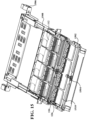
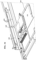
- FIG. 1 is a three-dimensional view of an example fiber optic tray 102 that includes a cassette mounting system according to one or more embodiments.
- the tray 102 is shown without cassettes in FIG. 1 for clarity.
- Example tray 102 is designed to hold multiple fiber optic cassettes, and to be installed in a fiber optic enclosure. It is to be appreciated, however, that the features described herein for mounting cassettes of different sizes on a common cassette mounting system are not limited to use in such fiber optic trays, but rather are applicable to any system in which fiber optic cassettes are to be mounted on a surface for management and organization of fiber optic connections.
- the example tray 102 depicted in FIG. 1 comprises two rows of cassette bays 106 - a lower row (including cassette bay 106A) located on the main tray surface, and an upper row (including cassette bay 106B) located on a raised mounting interface 104 that is elevated above the main tray surface.
- Each cassette bay 106 is defined by a pair of parallel rail guides 108 on the left and right sides of the bay.
- the rail guides 108 are designed to interface with rails located along the left and right sides of the respective cassettes or adapter plates, as will be described in more detail below.
- the rail guides 108 are spaced substantially equidistant along the respective mounting surfaces, such that the space between adjacent rail guides 108 generally corresponds to the width of a single-gang cassette to be mounted on the tray 102.
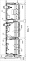
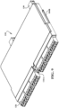
- FIG. 2 is a three-dimensional view of the example fiber optic cassette tray 102 with a number of cassettes and adapter plates installed thereon
- FIG. 3 is a top view of the installed cassettes.
- the cassette mounting system allows a user to mount cassettes of different sizes (e.g., both single-gang and multi-gang cassettes) on the same cassette tray 102 simultaneously at any position on the mounting interfaces.
- a single-gang cassette 112, a dual-gang cassette 110, and a single-gang adapter plate 114 are mounted on the upper mounting interface 104 of tray 102 in selected positions.
Landscapes
- Physics & Mathematics (AREA)
- General Physics & Mathematics (AREA)
- Optics & Photonics (AREA)
- Light Guides In General And Applications Therefor (AREA)
- Optical Couplings Of Light Guides (AREA)
Claims (11)
- Lichtwellenleiterkassetten-Montagesystem, Folgendes umfassend:eine Lichtwellenleiterkassette (110, 112), die konfiguriert ist, um eine horizontale Reihe von Lichtwellenleiter-Adaptern (126) entlang der Vorderkante der Kassette (110, 112) zu halten, wobei die Lichtwellenleiter-Adapter (126) konfiguriert sind, um Lichtwellenleiter-Steckverbinder aufzunehmen, die jeweilige Lichtwellenleiter abschließen; undein Lichtwellenleiterkassetten-Träger (102), das Schienenführungen (108) umfasst, die konfiguriert sind, um in jeweilige Schienen (404a, 404b) der Lichtwellenleiterkassette (110, 112) einzugreifen,wobei eine Schienenführung der Schienenführungen (108) einen länglichen Abschnitt einer Oberfläche des Lichtwellenleiterkassetten-Trägers (102) umfasst, der von der Oberfläche angehoben ist, um auf einer linken Seite und einer rechten Seite des länglichen Abschnitts Leisten zu bilden,wobei die Schienenführungen (108) konfiguriert sind, um die Lichtwellenleiterkassette (110, 112) auf dem Lichtwellenleiterkassetten-Träger (102) zu halten, wobei die Lichtwellenleiterkassette (110, 112) eine Einfach-Lichtwellenleiterkassette (112) oder eine Mehrfach-Lichtwellenleiterkassette (110) ist;wobei die Lichtwellenleiterkassette (110, 112) einen Einrastmechanismus (120) umfasst, der einen Einrastvorsprung (1006) umfasst, der konfiguriert ist, um in eine Öffnung (124) auf dem Lichtwellenleiterkassetten-Träger (102) einzugreifen, wobei der Einrastmechanismus (120) ferner einen Lösemechanismus (1002) umfasst,wobei der Lösemechanismus (1002) konfiguriert ist, um den Einrastvorsprung (1006) von der Öffnung (124) als Reaktion darauf freizugeben, dass Druck auf den Lösemechanismus (1002) ausgeübt wird, dadurch gekennzeichnet, dass der Lösemechanismus (1002) der Vorderseite der Lichtwellenleiterkassette (110, 112) zugewandt ist.
- Lichtwellenleiterkassetten-Montagesystem nach Anspruch 1, wobei die Schienenführung an einem vorderen Ende der Schienenführung eingekerbt ist, um einer Schiene der Lichtwellenleiterkassette (110, 112) zu ermöglichen, in die Schienenführung unter einer der Leisten einzutreten.
- Lichtwellenleiterkassetten-Montagesystem nach Anspruch 1, wobei die Lichtwellenleiterkassette eine Mehrfach-Lichtwellenleiterkassette (110) ist und wobei die Mehrfach-Lichtwellenleiterkassette (110) mindestens einen Freiraum zwischen zwei Fächern (604A, 604B) der Kassette umfasst, die konfiguriert ist, um einer Schienenführung zu ermöglichen, sich zwischen den zwei Fächern (604A, 604B) zu befinden, wenn die Lichtwellenleiterkassette (110, 112) auf dem Lichtwellenleiterkassetten-Träger (102) montiert ist.
- Lichtwellenleiterkassetten-Montagesystem nach Anspruch 1, wobei eine Schiene der Schienen (404a, 404b) der Lichtwellenleiterkassette (110, 112) eine Einkerbung umfasst, die in ein vorderes Ende der Schienenführung eingreift, um zu verhindern, dass die Lichtwellenleiterkassette (110, 112) nach hinten über eine Halteposition hinaus gelangt.
- Lichtwellenleiterkassetten-Montagesystem nach Anspruch 4, wobei der Einrastvorsprung (1006) konfiguriert ist, um in die Öffnung (124) als Reaktion darauf einzugreifen, dass die Lichtwellenleiterkassette (110, 112) die Halteposition erreicht, während sie nach hinten zwischen der Schienenführung und einer anderen Schienenführung geschoben wird.
- Lichtwellenleiterkassette nach Anspruch 1, wobei der Lösemechanismus (1002) konfiguriert ist, um sich als Reaktion darauf, dass der Druck auf den Lösemechanismus (1002) ausgeübt wird, um einen Schwenkpunkt zu drehen, und wobei eine Drehung des Lösemechanismus (1002) um den Schwenkpunkt eine Kontaktlasche auf dem Lösemechanismus (1002) veranlasst, den Einrastvorsprung frei von der Öffnung (124) anzuheben.
- Lichtwellenleiterkassetten-Montagesystem nach Anspruch 1, wobei der Einrastmechanismus (120) auf einer linken Seite der Lichtwellenleiterkassette (110, 112), auf einer rechten Seite der Einfach-Lichtwellenleiterkassette (112) oder in einer Fläche zwischen zwei Fächern (604A, 604B) der Mehrfach-Lichtwellenleiterkassette (110) angeordnet ist.
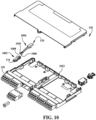
- Lichtwellenleiterkassetten-Montagesystem nach Anspruch 1, ferner umfassend ein Gehäuse (1508), das konfiguriert ist, um den Lichtwellenleiterkassetten-Träger (102) unterzubringen, wobei das Gehäuse (1508) Trägerführungen umfasst, die jeweils an einer linken Innenwand und einer rechten Innenwand des Gehäuses (1508) angeordnet sind, und wobei die Trägerführungen Führungskanäle umfassen, die konfiguriert sind, um in eine linke Kante oder eine rechte Kante des Lichtwellenleiterkassetten-Trägers (102) einzugreifen.
- Lichtwellenleiterkassetten-Montagesystem nach Anspruch 1, wobei der Lichtwellenleiterkassetten-Träger (102) mindestens zwei Trägerebenen umfasst.
- Lichtwellenleiterkassetten-Montagesystem nach Anspruch 1, ferner umfassend eine Reihe von Lichtwellenleiter-Adaptern, die entlang einer Vorderkante der Lichtwellenleiterkassette (110, 112) angeordnet sind, wobei die Lichtwellenleiter-Adapter konfiguriert sind, um Lichtwellenleiter-Steckverbinder aufzunehmen, die jeweilige Lichtwellenleiter abschließen.
- Lichtwellenleiterkassetten-Montagesystem nach Anspruch 1, wobei die Lichtwellenleiterkassette eine Mehrfach-Lichtwellenleiterkassette (110) ist und wobei die Mehrfach-Lichtwellenleiterkassette (110) mindestens einen Freiraum zwischen zwei Fächern der Kassette (110) umfasst, die konfiguriert ist, um Lichtwellenleitern zu ermöglichen, zwischen mindestens einem ersten Fach (604A) und einem zweiten Fach (604B) hindurchzulaufen.
Applications Claiming Priority (3)
| Application Number | Priority Date | Filing Date | Title |
|---|---|---|---|
| US14/937,817 US9690064B2 (en) | 2015-11-10 | 2015-11-10 | Multi-gang cassette system |
| PCT/US2016/060907 WO2017083256A1 (en) | 2015-11-10 | 2016-11-08 | Multi-gang fiber optic cassette system |
| EP16864832.7A EP3374813B1 (de) | 2015-11-10 | 2016-11-08 | Faseroptisches kassettensystem mit mehreren gängen |
Related Parent Applications (2)
| Application Number | Title | Priority Date | Filing Date |
|---|---|---|---|
| EP16864832.7A Division EP3374813B1 (de) | 2015-11-10 | 2016-11-08 | Faseroptisches kassettensystem mit mehreren gängen |
| EP16864832.7A Division-Into EP3374813B1 (de) | 2015-11-10 | 2016-11-08 | Faseroptisches kassettensystem mit mehreren gängen |
Publications (2)
| Publication Number | Publication Date |
|---|---|
| EP4001983A1 EP4001983A1 (de) | 2022-05-25 |
| EP4001983B1 true EP4001983B1 (de) | 2025-06-25 |
Family
ID=58664270
Family Applications (2)
| Application Number | Title | Priority Date | Filing Date |
|---|---|---|---|
| EP16864832.7A Active EP3374813B1 (de) | 2015-11-10 | 2016-11-08 | Faseroptisches kassettensystem mit mehreren gängen |
| EP22151149.6A Active EP4001983B1 (de) | 2015-11-10 | 2016-11-08 | Montagesystem von faseroptischen kassetten |
Family Applications Before (1)
| Application Number | Title | Priority Date | Filing Date |
|---|---|---|---|
| EP16864832.7A Active EP3374813B1 (de) | 2015-11-10 | 2016-11-08 | Faseroptisches kassettensystem mit mehreren gängen |
Country Status (5)
| Country | Link |
|---|---|
| US (1) | US9690064B2 (de) |
| EP (2) | EP3374813B1 (de) |
| CA (1) | CA3004904C (de) |
| MX (1) | MX2018005310A (de) |
| WO (1) | WO2017083256A1 (de) |
Families Citing this family (22)
| Publication number | Priority date | Publication date | Assignee | Title |
|---|---|---|---|---|
| US11294136B2 (en) | 2008-08-29 | 2022-04-05 | Corning Optical Communications LLC | High density and bandwidth fiber optic apparatuses and related equipment and methods |
| US8452148B2 (en) | 2008-08-29 | 2013-05-28 | Corning Cable Systems Llc | Independently translatable modules and fiber optic equipment trays in fiber optic equipment |
| WO2010148336A1 (en) | 2009-06-19 | 2010-12-23 | Corning Cable Systems Llc | High density and bandwidth fiber optic apparatuses and related equipment and methods |
| US10295773B2 (en) | 2017-03-29 | 2019-05-21 | Leviton Manufacturing Co., Inc. | Segregated fiber in a splice cassette |
| US10670822B2 (en) | 2017-06-28 | 2020-06-02 | Afl Telecommunications Llc | High density patch panel with modular cassettes |
| CA3019081C (en) * | 2017-10-03 | 2025-05-06 | Belden Canada Ulc | MODULAR FIBER OPTIC CASSETTE, SYSTEM AND METHOD |
| US10809479B2 (en) * | 2018-01-16 | 2020-10-20 | Belden Canada Ulc | Fiber optic cassette system with reversible cassettes |
| US10571640B2 (en) * | 2018-06-22 | 2020-02-25 | Panduit Corp. | Cassette adapter and method of installation |
| US11048055B2 (en) * | 2018-11-16 | 2021-06-29 | Panduit Corp. | Fiber optic cassette |
| US10663687B1 (en) | 2018-12-14 | 2020-05-26 | Leviton Manufacturing Co., Inc. | Fiber optic pigtail assembly |
| US10969554B2 (en) | 2019-04-01 | 2021-04-06 | Afl Telecommunications Llc | Fiber optic tray systems |
| EP3957078B1 (de) | 2019-04-17 | 2023-07-05 | Afl Ig Llc | Patch-platte mit hubkassettenentfernung |
| CN110596836B (zh) * | 2019-09-04 | 2020-09-01 | 合肥昌嵩精密制造有限公司 | 一种新型光缆入户多芯终端盒 |
| MX2023002749A (es) | 2020-09-17 | 2023-04-14 | Panduit Corp | Armazon de distribucion optica y empalme que incluye gabinetes. |
| US11531382B2 (en) * | 2021-02-12 | 2022-12-20 | Hewlett Packard Enterprise Development Lp | Multi-row pluggable high-radix modules |
| EP4295650A4 (de) | 2021-02-18 | 2025-01-08 | CommScope Technologies LLC | Kassettenverriegelungsanordnungen |
| WO2022178317A1 (en) * | 2021-02-18 | 2022-08-25 | Commscope Technologies Llc | Communications panel system |
| US11971598B2 (en) | 2021-02-18 | 2024-04-30 | Commscope Technologies Llc | Tray arrangements for cassettes |
| US20240361555A1 (en) * | 2021-07-16 | 2024-10-31 | Commscope Technologies Llc | Panel systems with slidable cassettes |
| US12411300B2 (en) * | 2021-09-15 | 2025-09-09 | Belden Canada Ulc | Cassette with reversible securing component and system |
| WO2024137769A1 (en) * | 2022-12-20 | 2024-06-27 | Ppc Broadband, Inc. | Mounting bracket assembly structurally configured to mount optical fiber management components, including different size communication devices, in an enclosure |
| WO2025123011A1 (en) * | 2023-12-07 | 2025-06-12 | Commscope Technologies Llc | Communications panel system |
Family Cites Families (36)
| Publication number | Priority date | Publication date | Assignee | Title |
|---|---|---|---|---|
| JPS602993B2 (ja) | 1978-05-27 | 1985-01-25 | ブラザー工業株式会社 | タイプライタ− |
| US4528728A (en) | 1982-10-13 | 1985-07-16 | Rose Manufacturing Company | Locking snap hook |
| US4659119A (en) | 1983-12-29 | 1987-04-21 | Dril-Quip, Inc. | Latching connector |
| US4692809A (en) | 1984-11-20 | 1987-09-08 | Hughes Aircraft Company | Integrated touch paint system for displays |
| US4944568A (en) | 1989-09-05 | 1990-07-31 | Molex Incorporated | Fiber optic connector assembly |
| US5004866A (en) | 1989-10-27 | 1991-04-02 | International Business Machines Corp. | Self-contained grounding strip |
| DE69220688T2 (de) | 1991-02-08 | 1998-01-15 | Canon Kk | Bandladevorrichtung |
| US5312263A (en) | 1993-08-12 | 1994-05-17 | Ford Motor Company | Removable radio bezel connector |
| JPH0935816A (ja) | 1995-07-19 | 1997-02-07 | Whitaker Corp:The | ラッチ付電気コネクタ |
| US6485322B1 (en) | 1999-10-01 | 2002-11-26 | Jds Uniphase Corporation | Removable latch and bezel EMI grounding feature for fiber-optic transceivers |
| US6607308B2 (en) | 2001-02-12 | 2003-08-19 | E20 Communications, Inc. | Fiber-optic modules with shielded housing/covers having mixed finger types |
| US7314318B2 (en) | 2001-03-15 | 2008-01-01 | International Business Machines Corporation | Compact optical transceivers including thermal distributing and electromagnetic shielding systems and methods thereof |
| US6796715B2 (en) | 2001-04-14 | 2004-09-28 | E20 Communications, Inc. | Fiber optic modules with pull-action de-latching mechanisms |
| US6626697B1 (en) | 2002-11-07 | 2003-09-30 | Tyco Electronics Corp. | Network connection sensing assembly |
| JP4567958B2 (ja) | 2003-01-21 | 2010-10-27 | 日立電線株式会社 | ロック機構付きパッケージ |
| JP4117476B2 (ja) | 2003-05-30 | 2008-07-16 | 日本電気株式会社 | 光モジュール、光モジュールとケージとの組立体、光モジュールとケージとのロック方法及びロック解除方法 |
| US7201411B2 (en) | 2004-11-18 | 2007-04-10 | Illinois Tool Works Inc | Push latch |
| US7298946B2 (en) | 2004-12-22 | 2007-11-20 | Hewlett-Packard Development Company, L.P. | Multi-fiber cable for efficient manageability of optical system |
| US7473131B2 (en) | 2006-02-02 | 2009-01-06 | Tyco Electronics Corporation | Connector with compliant EMI gasket |
| US7509015B2 (en) | 2006-07-26 | 2009-03-24 | Ortronics, Inc. | Secure fiber optic network cassette assembly |
| US7689089B2 (en) | 2006-10-11 | 2010-03-30 | Panduit Corp. | Release latch for pre-terminated cassette |
| US7841779B1 (en) | 2007-09-07 | 2010-11-30 | Fourte Design & Development, Llc | Fiber optic module release mechanism |
| US8454254B2 (en) | 2007-11-28 | 2013-06-04 | Kinesis Corporation | Support accessory for split keyboard |
| US8011950B2 (en) | 2009-02-18 | 2011-09-06 | Cinch Connectors, Inc. | Electrical connector |
| US8712206B2 (en) | 2009-06-19 | 2014-04-29 | Corning Cable Systems Llc | High-density fiber optic modules and module housings and related equipment |
| EP2446312A1 (de) | 2009-06-22 | 2012-05-02 | Corning Cable Systems LLC | Positionierungsvorrichtung für glasfaserkabel |
| US8062049B2 (en) | 2010-01-15 | 2011-11-22 | Tyco Electronics Corporation | Latch assembly for a connector assembly |
| US8147272B2 (en) | 2010-02-04 | 2012-04-03 | Tyco Electronics Corporation | Header connector assembly |
| US9116324B2 (en) * | 2010-10-29 | 2015-08-25 | Corning Cable Systems Llc | Stacked fiber optic modules and fiber optic equipment configured to support stacked fiber optic modules |
| US8740478B2 (en) | 2012-01-13 | 2014-06-03 | Avago Technologies General Ip (Singapore) Pte. Ltd. | Optical module with bare fiber clamp |
| US8781284B2 (en) | 2012-08-01 | 2014-07-15 | Leviton Manufacturing Co., Inc. | Low profile copper and fiber optic cassettes |
| CN203012204U (zh) | 2012-12-11 | 2013-06-19 | 深圳日海通讯技术股份有限公司 | 模块盒装配结构及具有该模块盒装配结构的配线设备 |
| CN203573012U (zh) | 2013-12-02 | 2014-04-30 | 长飞光纤光缆股份有限公司 | 一种模块式光纤配线架 |
| WO2016066614A1 (en) | 2014-10-27 | 2016-05-06 | Commscope Emea Limited | Splice module for fiber blade |
| CN204925469U (zh) | 2015-07-23 | 2015-12-30 | 深圳市易飞扬通信技术有限公司 | 光纤安装结构及设有该结构的机箱 |
| CN205787267U (zh) | 2016-05-25 | 2016-12-07 | 连展科技电子(昆山)有限公司 | 光纤卡匣轨道结构 |
-
2015
- 2015-11-10 US US14/937,817 patent/US9690064B2/en active Active
-
2016
- 2016-11-08 EP EP16864832.7A patent/EP3374813B1/de active Active
- 2016-11-08 CA CA3004904A patent/CA3004904C/en active Active
- 2016-11-08 MX MX2018005310A patent/MX2018005310A/es unknown
- 2016-11-08 EP EP22151149.6A patent/EP4001983B1/de active Active
- 2016-11-08 WO PCT/US2016/060907 patent/WO2017083256A1/en not_active Ceased
Also Published As
| Publication number | Publication date |
|---|---|
| MX2018005310A (es) | 2018-08-15 |
| EP3374813A4 (de) | 2019-06-12 |
| US9690064B2 (en) | 2017-06-27 |
| US20170131500A1 (en) | 2017-05-11 |
| EP4001983A1 (de) | 2022-05-25 |
| WO2017083256A1 (en) | 2017-05-18 |
| CA3004904A1 (en) | 2017-05-18 |
| EP3374813A1 (de) | 2018-09-19 |
| CA3004904C (en) | 2024-04-02 |
| EP3374813B1 (de) | 2022-03-09 |
Similar Documents
| Publication | Publication Date | Title |
|---|---|---|
| EP4001983B1 (de) | Montagesystem von faseroptischen kassetten | |
| EP2867712B1 (de) | Faseroptische modultabletts und schubladen für faseroptische vorrichtung | |
| US12265275B2 (en) | High density patch panel with modular cassettes | |
| EP3446554B1 (de) | Telekommunikationschassis mit verschiebbaren schalen | |
| US20250231363A1 (en) | Reversible cassette for fiber optic cassette system | |
| CN105705976A (zh) | 通信底盘 | |
| US12169319B2 (en) | Patch panel with lifting cassette removal | |
| EP3617762B1 (de) | Abnehmbare einfassung für kassettenmontage | |
| WO2011094944A1 (en) | Adapter holder module | |
| EP4266103B1 (de) | Lichtwellenleitersteckervorrichtung | |
| US20190235185A1 (en) | Cable router |
Legal Events
| Date | Code | Title | Description |
|---|---|---|---|
| PUAI | Public reference made under article 153(3) epc to a published international application that has entered the european phase |
Free format text: ORIGINAL CODE: 0009012 |
|
| STAA | Information on the status of an ep patent application or granted ep patent |
Free format text: STATUS: THE APPLICATION HAS BEEN PUBLISHED |
|
| AC | Divisional application: reference to earlier application |
Ref document number: 3374813 Country of ref document: EP Kind code of ref document: P |
|
| AK | Designated contracting states |
Kind code of ref document: A1 Designated state(s): AL AT BE BG CH CY CZ DE DK EE ES FI FR GB GR HR HU IE IS IT LI LT LU LV MC MK MT NL NO PL PT RO RS SE SI SK SM TR |
|
| STAA | Information on the status of an ep patent application or granted ep patent |
Free format text: STATUS: REQUEST FOR EXAMINATION WAS MADE |
|
| 17P | Request for examination filed |
Effective date: 20221019 |
|
| RBV | Designated contracting states (corrected) |
Designated state(s): AL AT BE BG CH CY CZ DE DK EE ES FI FR GB GR HR HU IE IS IT LI LT LU LV MC MK MT NL NO PL PT RO RS SE SI SK SM TR |
|
| GRAP | Despatch of communication of intention to grant a patent |
Free format text: ORIGINAL CODE: EPIDOSNIGR1 |
|
| STAA | Information on the status of an ep patent application or granted ep patent |
Free format text: STATUS: GRANT OF PATENT IS INTENDED |
|
| INTG | Intention to grant announced |
Effective date: 20240822 |
|
| GRAJ | Information related to disapproval of communication of intention to grant by the applicant or resumption of examination proceedings by the epo deleted |
Free format text: ORIGINAL CODE: EPIDOSDIGR1 |
|
| STAA | Information on the status of an ep patent application or granted ep patent |
Free format text: STATUS: REQUEST FOR EXAMINATION WAS MADE |
|
| INTC | Intention to grant announced (deleted) | ||
| GRAP | Despatch of communication of intention to grant a patent |
Free format text: ORIGINAL CODE: EPIDOSNIGR1 |
|
| STAA | Information on the status of an ep patent application or granted ep patent |
Free format text: STATUS: GRANT OF PATENT IS INTENDED |
|
| INTG | Intention to grant announced |
Effective date: 20250205 |
|
| GRAS | Grant fee paid |
Free format text: ORIGINAL CODE: EPIDOSNIGR3 |
|
| GRAA | (expected) grant |
Free format text: ORIGINAL CODE: 0009210 |
|
| STAA | Information on the status of an ep patent application or granted ep patent |
Free format text: STATUS: THE PATENT HAS BEEN GRANTED |
|
| P01 | Opt-out of the competence of the unified patent court (upc) registered |
Free format text: CASE NUMBER: APP_21544/2025 Effective date: 20250506 |
|
| AC | Divisional application: reference to earlier application |
Ref document number: 3374813 Country of ref document: EP Kind code of ref document: P |
|
| AK | Designated contracting states |
Kind code of ref document: B1 Designated state(s): AL AT BE BG CH CY CZ DE DK EE ES FI FR GB GR HR HU IE IS IT LI LT LU LV MC MK MT NL NO PL PT RO RS SE SI SK SM TR |
|
| REG | Reference to a national code |
Ref country code: GB Ref legal event code: FG4D |
|
| REG | Reference to a national code |
Ref country code: CH Ref legal event code: EP |
|
| REG | Reference to a national code |
Ref country code: DE Ref legal event code: R096 Ref document number: 602016092722 Country of ref document: DE |
|
| REG | Reference to a national code |
Ref country code: CH Ref legal event code: EP |
|
| REG | Reference to a national code |
Ref country code: IE Ref legal event code: FG4D |
|
| PG25 | Lapsed in a contracting state [announced via postgrant information from national office to epo] |
Ref country code: FI Free format text: LAPSE BECAUSE OF FAILURE TO SUBMIT A TRANSLATION OF THE DESCRIPTION OR TO PAY THE FEE WITHIN THE PRESCRIBED TIME-LIMIT Effective date: 20250625 |
|
| REG | Reference to a national code |
Ref country code: LT Ref legal event code: MG9D |
|
| PG25 | Lapsed in a contracting state [announced via postgrant information from national office to epo] |
Ref country code: NO Free format text: LAPSE BECAUSE OF FAILURE TO SUBMIT A TRANSLATION OF THE DESCRIPTION OR TO PAY THE FEE WITHIN THE PRESCRIBED TIME-LIMIT Effective date: 20250925 Ref country code: GR Free format text: LAPSE BECAUSE OF FAILURE TO SUBMIT A TRANSLATION OF THE DESCRIPTION OR TO PAY THE FEE WITHIN THE PRESCRIBED TIME-LIMIT Effective date: 20250926 |
|
| REG | Reference to a national code |
Ref country code: NL Ref legal event code: FP |
|
| PG25 | Lapsed in a contracting state [announced via postgrant information from national office to epo] |
Ref country code: BG Free format text: LAPSE BECAUSE OF FAILURE TO SUBMIT A TRANSLATION OF THE DESCRIPTION OR TO PAY THE FEE WITHIN THE PRESCRIBED TIME-LIMIT Effective date: 20250625 |
|
| PG25 | Lapsed in a contracting state [announced via postgrant information from national office to epo] |
Ref country code: HR Free format text: LAPSE BECAUSE OF FAILURE TO SUBMIT A TRANSLATION OF THE DESCRIPTION OR TO PAY THE FEE WITHIN THE PRESCRIBED TIME-LIMIT Effective date: 20250625 |
|
| PG25 | Lapsed in a contracting state [announced via postgrant information from national office to epo] |
Ref country code: RS Free format text: LAPSE BECAUSE OF FAILURE TO SUBMIT A TRANSLATION OF THE DESCRIPTION OR TO PAY THE FEE WITHIN THE PRESCRIBED TIME-LIMIT Effective date: 20250925 |
|
| PG25 | Lapsed in a contracting state [announced via postgrant information from national office to epo] |
Ref country code: LV Free format text: LAPSE BECAUSE OF FAILURE TO SUBMIT A TRANSLATION OF THE DESCRIPTION OR TO PAY THE FEE WITHIN THE PRESCRIBED TIME-LIMIT Effective date: 20250625 |
|
| PGFP | Annual fee paid to national office [announced via postgrant information from national office to epo] |
Ref country code: NL Payment date: 20251016 Year of fee payment: 10 |
|
| PG25 | Lapsed in a contracting state [announced via postgrant information from national office to epo] |
Ref country code: PT Free format text: LAPSE BECAUSE OF FAILURE TO SUBMIT A TRANSLATION OF THE DESCRIPTION OR TO PAY THE FEE WITHIN THE PRESCRIBED TIME-LIMIT Effective date: 20251027 |
|
| REG | Reference to a national code |
Ref country code: AT Ref legal event code: MK05 Ref document number: 1807043 Country of ref document: AT Kind code of ref document: T Effective date: 20250625 |
|
| PG25 | Lapsed in a contracting state [announced via postgrant information from national office to epo] |
Ref country code: IS Free format text: LAPSE BECAUSE OF FAILURE TO SUBMIT A TRANSLATION OF THE DESCRIPTION OR TO PAY THE FEE WITHIN THE PRESCRIBED TIME-LIMIT Effective date: 20251025 |
|
| PGFP | Annual fee paid to national office [announced via postgrant information from national office to epo] |
Ref country code: DE Payment date: 20251021 Year of fee payment: 10 |
|
| PGFP | Annual fee paid to national office [announced via postgrant information from national office to epo] |
Ref country code: GB Payment date: 20251016 Year of fee payment: 10 |
|
| PG25 | Lapsed in a contracting state [announced via postgrant information from national office to epo] |
Ref country code: AT Free format text: LAPSE BECAUSE OF FAILURE TO SUBMIT A TRANSLATION OF THE DESCRIPTION OR TO PAY THE FEE WITHIN THE PRESCRIBED TIME-LIMIT Effective date: 20250625 Ref country code: SM Free format text: LAPSE BECAUSE OF FAILURE TO SUBMIT A TRANSLATION OF THE DESCRIPTION OR TO PAY THE FEE WITHIN THE PRESCRIBED TIME-LIMIT Effective date: 20250625 |
|
| PGFP | Annual fee paid to national office [announced via postgrant information from national office to epo] |
Ref country code: IT Payment date: 20251027 Year of fee payment: 10 |
|
| PGFP | Annual fee paid to national office [announced via postgrant information from national office to epo] |
Ref country code: FR Payment date: 20251016 Year of fee payment: 10 |
|
| PG25 | Lapsed in a contracting state [announced via postgrant information from national office to epo] |
Ref country code: CZ Free format text: LAPSE BECAUSE OF FAILURE TO SUBMIT A TRANSLATION OF THE DESCRIPTION OR TO PAY THE FEE WITHIN THE PRESCRIBED TIME-LIMIT Effective date: 20250625 |
|
| PG25 | Lapsed in a contracting state [announced via postgrant information from national office to epo] |
Ref country code: PL Free format text: LAPSE BECAUSE OF FAILURE TO SUBMIT A TRANSLATION OF THE DESCRIPTION OR TO PAY THE FEE WITHIN THE PRESCRIBED TIME-LIMIT Effective date: 20250625 |
|
| PG25 | Lapsed in a contracting state [announced via postgrant information from national office to epo] |
Ref country code: EE Free format text: LAPSE BECAUSE OF FAILURE TO SUBMIT A TRANSLATION OF THE DESCRIPTION OR TO PAY THE FEE WITHIN THE PRESCRIBED TIME-LIMIT Effective date: 20250625 |
|
| PG25 | Lapsed in a contracting state [announced via postgrant information from national office to epo] |
Ref country code: SK Free format text: LAPSE BECAUSE OF FAILURE TO SUBMIT A TRANSLATION OF THE DESCRIPTION OR TO PAY THE FEE WITHIN THE PRESCRIBED TIME-LIMIT Effective date: 20250625 |
|
| PG25 | Lapsed in a contracting state [announced via postgrant information from national office to epo] |
Ref country code: ES Free format text: LAPSE BECAUSE OF FAILURE TO SUBMIT A TRANSLATION OF THE DESCRIPTION OR TO PAY THE FEE WITHIN THE PRESCRIBED TIME-LIMIT Effective date: 20250625 |
|
| PG25 | Lapsed in a contracting state [announced via postgrant information from national office to epo] |
Ref country code: RO Free format text: LAPSE BECAUSE OF FAILURE TO SUBMIT A TRANSLATION OF THE DESCRIPTION OR TO PAY THE FEE WITHIN THE PRESCRIBED TIME-LIMIT Effective date: 20250625 |
|
| PG25 | Lapsed in a contracting state [announced via postgrant information from national office to epo] |
Ref country code: DK Free format text: LAPSE BECAUSE OF FAILURE TO SUBMIT A TRANSLATION OF THE DESCRIPTION OR TO PAY THE FEE WITHIN THE PRESCRIBED TIME-LIMIT Effective date: 20250625 |
|
| PLBE | No opposition filed within time limit |
Free format text: ORIGINAL CODE: 0009261 |
|
| STAA | Information on the status of an ep patent application or granted ep patent |
Free format text: STATUS: NO OPPOSITION FILED WITHIN TIME LIMIT |