EP4002016B1 - Watch with mechanical movement with force control mechanism - Google Patents
Watch with mechanical movement with force control mechanism Download PDFInfo
- Publication number
- EP4002016B1 EP4002016B1 EP20208925.6A EP20208925A EP4002016B1 EP 4002016 B1 EP4002016 B1 EP 4002016B1 EP 20208925 A EP20208925 A EP 20208925A EP 4002016 B1 EP4002016 B1 EP 4002016B1
- Authority
- EP
- European Patent Office
- Prior art keywords
- wheel
- watch
- seconds
- mechanical movement
- fixed
- Prior art date
- Legal status (The legal status is an assumption and is not a legal conclusion. Google has not performed a legal analysis and makes no representation as to the accuracy of the status listed.)
- Active
Links
Images


Classifications
-
- G—PHYSICS
- G04—HOROLOGY
- G04B—MECHANICALLY-DRIVEN CLOCKS OR WATCHES; MECHANICAL PARTS OF CLOCKS OR WATCHES IN GENERAL; TIME PIECES USING THE POSITION OF THE SUN, MOON OR STARS
- G04B15/00—Escapements
-
- G—PHYSICS
- G04—HOROLOGY
- G04B—MECHANICALLY-DRIVEN CLOCKS OR WATCHES; MECHANICAL PARTS OF CLOCKS OR WATCHES IN GENERAL; TIME PIECES USING THE POSITION OF THE SUN, MOON OR STARS
- G04B19/00—Indicating the time by visual means
- G04B19/24—Clocks or watches with date or week-day indicators, i.e. calendar clocks or watches; Clockwork calendars
- G04B19/243—Clocks or watches with date or week-day indicators, i.e. calendar clocks or watches; Clockwork calendars characterised by the shape of the date indicator
- G04B19/257—Clocks or watches with date or week-day indicators, i.e. calendar clocks or watches; Clockwork calendars characterised by the shape of the date indicator drum-shaped or three-dimensional shaped
- G04B19/2573—Driving or releasing mechanisms wherein the date indicators are driven or released mechanically by a clockwork movement
- G04B19/2575—Driving or releasing mechanisms wherein the date indicators are driven or released mechanically by a clockwork movement driven or released stepwise by the clockwork movement
-
- G—PHYSICS
- G04—HOROLOGY
- G04B—MECHANICALLY-DRIVEN CLOCKS OR WATCHES; MECHANICAL PARTS OF CLOCKS OR WATCHES IN GENERAL; TIME PIECES USING THE POSITION OF THE SUN, MOON OR STARS
- G04B15/00—Escapements
- G04B15/06—Free escapements
- G04B15/08—Lever escapements
-
- G—PHYSICS
- G04—HOROLOGY
- G04B—MECHANICALLY-DRIVEN CLOCKS OR WATCHES; MECHANICAL PARTS OF CLOCKS OR WATCHES IN GENERAL; TIME PIECES USING THE POSITION OF THE SUN, MOON OR STARS
- G04B13/00—Gearwork
- G04B13/002—Gearwork where rotation in one direction is changed into a stepping movement
-
- G—PHYSICS
- G04—HOROLOGY
- G04B—MECHANICALLY-DRIVEN CLOCKS OR WATCHES; MECHANICAL PARTS OF CLOCKS OR WATCHES IN GENERAL; TIME PIECES USING THE POSITION OF THE SUN, MOON OR STARS
- G04B13/00—Gearwork
- G04B13/02—Wheels; Pinions; Spindles; Pivots
-
- G—PHYSICS
- G04—HOROLOGY
- G04B—MECHANICALLY-DRIVEN CLOCKS OR WATCHES; MECHANICAL PARTS OF CLOCKS OR WATCHES IN GENERAL; TIME PIECES USING THE POSITION OF THE SUN, MOON OR STARS
- G04B15/00—Escapements
- G04B15/14—Component parts or constructional details, e.g. construction of the lever or the escape wheel
-
- G—PHYSICS
- G04—HOROLOGY
- G04B—MECHANICALLY-DRIVEN CLOCKS OR WATCHES; MECHANICAL PARTS OF CLOCKS OR WATCHES IN GENERAL; TIME PIECES USING THE POSITION OF THE SUN, MOON OR STARS
- G04B17/00—Mechanisms for stabilising frequency
- G04B17/20—Compensation of mechanisms for stabilising frequency
- G04B17/28—Compensation of mechanisms for stabilising frequency for the effect of imbalance of the weights, e.g. tourbillon
- G04B17/285—Tourbillons or carrousels
-
- G—PHYSICS
- G04—HOROLOGY
- G04B—MECHANICALLY-DRIVEN CLOCKS OR WATCHES; MECHANICAL PARTS OF CLOCKS OR WATCHES IN GENERAL; TIME PIECES USING THE POSITION OF THE SUN, MOON OR STARS
- G04B19/00—Indicating the time by visual means
- G04B19/02—Back-gearing arrangements between gear train and hands
Definitions
- the invention relates to a mechanical movement watch with a force control mechanism, such as the force due to gravity when wearing the watch and of the jumping second type.
- the force control mechanism may be a tourbillon mechanism mounted at the escapement.
- the tourbillon cage surrounds the escapement mechanism and preferably the cage makes a complete rotation every minute with in particular 60 jumps of a second made.
- a tourbillon also called a "rotating cage”
- a tourbillon is a watch complication, added to the escapement mechanism, intended to improve the precision of mechanical watches by counterbalancing the disturbances of the isochronism of the resonator due to the Earth's gravity.
- the fundamental criterion which marks a tourbillon, in comparison with a carousel in particular, is the presence of a fixed gear train on which the tourbillon cage meshes.
- the tourbillon cage is rotatably mounted between two fixing points.
- Gravity is also taken into account to compensate for any disturbances in the isochronism of the resonator.
- the escapement is coupled to the resonator. It interacts with it once or twice per oscillation period.
- the angle traveled by the resonator during the interaction is called the lift angle.
- the rest of the resonator's path is called the additional angle or arc.
- the resonator can be in contact with the escapement (rubbing rest escapement) or without contact (free escapement).
- the escapement performs two main phases, which are the release (or counting) and the impulse (or maintenance).
- the jumping second is intended to display the second in steps of a whole second, which corresponds on a 60-second dial to 6° of angle per second.
- This jumping second is often associated with constant force mechanisms that take advantage of the particular construction of this jumping second.
- Dead second or fixed second mechanisms also approach these constructions with the particularity of being able to stop the second at will like a chronograph.
- a mechanism for periodically jumping forward a pivoting cage carrying a wheel and an escapement pinion and an anchor cooperating with the wheel and a balance spring.
- it comprises retaining means for authorizing or prohibiting the pivoting of said cage depending on the movements or not.
- stopping means for authorizing or prohibiting the pivoting of the retaining means depending on their angular position.
- a constant force device periodically makes the retaining means cooperate. This device comprises a whip designed to perform complete revolutions.
- Some of these mechanisms can become desynchronized after complete disarming, and go into a blocking position. This requires a stop system linked to a power reserve mechanism, which will stop the mechanism before complete disarming.
- a constant force device for a watch, with dead seconds.
- This device makes it possible to move an axis of a mobile on a lever controlled by an energy storage spring, which tends to pivot the lever.
- the device comprises a pinion of a first seconds wheel of the movement, which meshes with a setting wheel pivotally mounted on this lever, and which meshes with the pinion of a second seconds wheel defining the mobile.
- the lever carrying a finger must adapt to cooperate with a ratchet toothing of a stop wheel, which meshes with the first seconds wheel.
- the gear train is blocked, in particular composed of the first seconds wheel and the setting wheel without force transmission of the first seconds wheel and the setting wheel.
- the second seconds wheel is controlled by the escapement and only turns when the latter is moved by the balance wheel.
- the spring is wound by moving the lever in the opposite direction, for which the spring exerts a torque on the lever that is lower than that exerted by the barrel spring on the lever, when the stop wheel is released.
- the utility model CN 209014916 U describes a tourbillon clock mechanism having a toothed wheel.
- the toothed wheel is composed of a central portion for the passage of an axis, connected by spring-type metal coils to an inner wall of a crown with external peripheral teeth.
- THE patent EP 3 356 690 B1 describes a watch component having a flexible pivot of the well-known separate crossed blade type, and having means for adjusting the position of the crossing point of the blades.
- WO 2018/193365 A1 depicted in Figure 8 is a timepiece with a force control mechanism comprising a jumping second wheel and a rotating locking device.
- the invention therefore aims to overcome the drawbacks of the state of the art by providing a watch with a mechanical movement with a force compensation or control mechanism of the jumping second type, overcoming the drawbacks of the aforementioned prior art devices.
- the invention relates to a watch with a mechanical movement with a force compensation or control mechanism of the second type. jumping, which includes the features defined in independent claim 1.
- An advantage of the mechanical movement watch with a force control mechanism lies in the fact that it comprises a second wheel for accumulating the energy necessary to maintain several oscillations of the escapement mechanism with the oscillator, in particular in a stop mode before switching to a jump mode.
- the second wheel maintains a few oscillations of the resonator or oscillator without part of the gear train coming from the barrel being driven.
- the second wheel releases a blocking element, such as a whip after a certain number of oscillations to move in particular the tourbillon cage by 6° in the clockwise direction (SAM) and the finishing gear train coming from the barrel defining a second wheel of the jumping second type.
- the whip is released and by it, the intermediate wheel linked to the whip, the medium wheel, the large medium wheel and the barrel to drive the tourbillon cage by a step of 6° in a direction opposite to the accumulation of the second wheel.
- the tourbillon cage can be moved angularly after a certain number of oscillations defining a second.
- the second wheel is intended to move in the stop phase by a certain number of small steps following the oscillations of the spiral spring of the oscillator linked to the escapement mechanism, which is of the Swiss anchor type.
- the second wheel In this stop phase or stop mode, the second wheel second rotates counterclockwise while being rotated by a flexible guide with elastic blades, which is pre-wound.
- a movable portion of this flexible guide is fixed on a face of the second wheel, while a fixed portion of this flexible guide is fixed on a support of the watch movement, such as a plate.
- the movable portion of this flexible guide is preferably fixed directly below the second wheel.
- the flexible guide is mounted by an axial opening, coaxially with a second pinion, which is the second and tourbillon pinion.
- the flexible guide with elastic blades comprises several elastic blades in series connecting more massive parts including the mobile and fixed portions of the flexible guide, and possibly other intermediate portions.
- the flexible guide with elastic blades in series can thus be produced with a more robust structure capable of ensuring the rotation of the second wheel with a return torque advantageously used to replace the spring of the force control mechanism and with better axial support.
- such a flexible guide with elastic blades makes it possible to have an absence of friction, wear and energy dissipation, as well as an absence of play and precise guidance.
- the watch with a mechanical movement with a force control mechanism and of the jumping second type can be with a tourbillon whose cage encloses an oscillator and an escapement mechanism as explained below, or according to a traditional mechanical movement without a tourbillon, which will be explained later with reference to the figure 4 .
- FIGS. 1 and 2 represent a part of a mechanical watch movement 1 which is shown without the energy source, such as the barrel which is the mainspring and which is connected, in this case, to a fusee connected by a chain to the barrel drum for its drive. Also not shown is a large medium wheel, which is driven in rotation by a toothing on the periphery of the spindle according to a traditional embodiment. This energy is applied in the form of a torque to the pinion of the middle wheel 10.
- FIGS. 1 and 2 therefore represent a part of a mechanical watch movement comprising a finishing gear train 5, 8, 9, 10 in which is arranged a force control mechanism of the mechanical watch movement 1.
- This force control mechanism may be similar to a constant force device.
- the finishing gear train is arranged between a source of energy not shown, which is preferably a spring barrel, and an escapement mechanism for example with a Swiss lever 13 and having an escape wheel 11 in the form of a wheel, alternately retained and released by an oscillator 14, which is preferably a balance spring and the energy for maintaining its oscillation is provided by said escape wheel 11.
- the escape wheel 11 is arranged to be able to rotate in the same direction of rotation at each half-oscillation of the oscillator 14.
- the escape wheel 11 meshes with a second wheel 2 which is hereinafter also defined as a fixed second wheel SFA.
- This second wheel 2 is called a fixed second wheel SFA, even if it is not fixed in its operation.
- This fixed second wheel SFA 2 can rotate counterclockwise (SIAM) to maintain the operation of the escapement mechanism linked to the oscillator in a stop mode, and rotate clockwise (SAM) in a jump mode to perform a jump corresponding to 1 second.
- SIAM counterclockwise
- SAM clockwise
- the fixed second wheel SFA 2 preferably has peripheral teeth meshing with a toothed escape pinion 12 coaxial with said escape wheel 11.
- the fixed second wheel SFA 2 rotates counterclockwise (SIAM) by the restoring force of the flexible guide 4 and drives the escape wheel 11 at each half-oscillation of the oscillator 14 via the escapement toothed pinion 12 so as to maintain the operation of the oscillator and the escapement mechanism in this stopping phase.
- SIAM counterclockwise
- the fixed seconds wheel SFA 2 pivots in SIAM on its flexible guide 4 around the tourbillon cage 15 without touching the latter, which is stopped.
- This SIAM pivoting of the SFA 2 is carried out until the moment of the release of the finishing gear train 5, 8, 9, 10 by which a jump of one second is carried out by the tourbillon cage 15 and its second pinion 5, driving with it the fixed seconds wheel SFA 2, which is connected to the escapement wheel set 11, in the clockwise jump phase SAM.
- the force control mechanism comprises on the one hand a rotary blocking element 7 arranged to cooperate with a stop member 3 in connection with the fixed second wheel SFA 2 in the stop mode.
- this stop member 3 may be a rack 3, rotatably mounted at a first end of the rack 3 around an axis 33 arranged for example between a movement mounting plate and a middle bridge not shown.
- a second free end of the rack 3 comprises in a blocking part, a finger-shaped edge portion 3b freely arranged inside a guide housing between two teeth of a cam 6.
- the cam 6 is fixed integrally with said fixed second wheel SFA 2 near its center so as to rotate the rack 3 in each direction.
- the second free end of the rack 3 further comprises a stop piece 3a, such as a pallet 3a, arranged on a side opposite the edge portion 3b and arranged to block the rotary blocking element 7 in a stopping mode.
- the pallet 3a can be made of a hard material reducing friction with the locking element 7 in contact of the pallet 3a in a stopping phase.
- This stopping part which is the pallet 3a, can be made of a friction-reducing material such as ruby.
- a flexible guide 4 with elastic blades 4a or spring blades, which is pre-wound, is connected directly to the fixed second wheel SFA 2.
- the flexible guide 4 acts as a spring on the fixed second wheel SFA 2.
- the flexible guide 4 comprises a movable portion 4c with at least one opening 17 but preferably two openings 17 for fixing on a face of the fixed second wheel SFA 2.
- the flexible guide 4 is fixed on a lower face of the fixed second wheel SFA 2.
- elastic blades 4a are defined, these blades can be of rectangular, hexagonal or even round cross section. These elastic blades have a geometry: length and section which must be well determined to ensure the spring function to drive the fixed second wheel SFA 2 in rotation with the necessary torque. We can refer to the work W. H. Wittrick indicated below, for the production of flexible guides 4 with elastic blades 4a.
- At least one fixing means 27 in or through the opening(s) 17 is thus provided to fix the fixed second wheel SFA 2 on the movable portion 4c of the flexible guide 4.
- this fixing means 27 can be at least one material extension of the fixed second wheel SFA 2 to form a single piece with the wheel.
- Two material extensions 27 can be provided to be inserted for example by force respectively into the two openings 17 of the movable portion 4c of the flexible guide 4 to ensure good support and without protruding from each opening 17.
- a border can also be provided around each material extension 27 and can come directly from the material with the corresponding material extension to ensure a space between the lower face of the fixed second wheel SFA 2 and an upper face of the flexible guide 4.
- the flexible guide 4 further comprises a fixed portion 4b with at least one opening 16, but preferably two openings 16 to be mounted and fixed by means of a screw and nut assembly not shown on a support of the watch movement, such as a plate.
- a screw and nut assembly not shown on a support of the watch movement, such as a plate.
- Several elastic blades 4a or portions of elastic blades connect the mobile portion 4c to the fixed portion 4b as well as intermediate portions possibly between the mobile 4c and fixed 4b portions.
- the flexible guide 4 is mounted by an axial opening, coaxially with the second pinion 5, and around an axial tube of the fixed second wheel SFA 2 coaxial with the axis of the second pinion 5.
- the fixing means may also be a screw and nut assembly passing through openings in the movable portion and the fixed second wheel SFA 2, but with this type of assembly, too much space is wasted.
- the fixing of the fixed portion 4b of the flexible guide 4 on the plate can be carried out by a means other than the screw and nut assembly, taking as an example the fixing of the fixed second wheel SFA 2 on the flexible guide 4.
- the elastic blades 4a of the flexible guide 4 In the rest position, that is to say as soon as the jump mode is switched to the stop mode, the elastic blades 4a of the flexible guide 4 must be pre-stressed to accumulate mechanical energy to rotate the fixed second wheel SFA 2 in particular in the counterclockwise direction (SIAM).
- the rotation of the fixed second wheel SFA 2 also drives the escapement wheel 11 via an escapement pinion 12 coaxial with the escapement wheel of the Swiss lever escapement mechanism 13. This is advantageous for keeping the escapement mechanism with the oscillator 14 in operation in this stopping phase by the mechanical energy stored in the flexible guide 4 with elastic blades 4a. acting on the fixed second wheel SFA 2 to make it rotate in a counterclockwise direction (SIAM).
- SIAM counterclockwise direction
- the rack 3 is connected without the action of a spring to a cam 6 fixed on the fixed second wheel SFA 2 to block or release said finishing gear train according to the angular position of said fixed second wheel SFA 2 by retaining a whip 7, as a blocking element.
- This whip 7 comes into contact with a stop piece 3a of the blocking part of the rack 3.
- This stop piece is a pallet 3a, as described above.
- the fixed second wheel SFA 2 can rotate by 5 small steps corresponding to 6° of angle representing 1 second in the opposite direction.
- the whip 7 is itself driven by the going train and retained by the stop piece 3a. Once released at the end of the stopping phase, the rotation of the rack 3 releases the whip 7 which triggers the jump phase.
- the whip 7 performs a rotation corresponding to a jump of 1 second, driven by the going train, in the case shown, a half-turn.
- the finishing gear train similarly drives the tourbillon cage 15 via the second pinion 5 and the fixed second wheel SFA 2 in a clockwise direction (SAM), which resets the flexible guide 4.
- SAM clockwise direction
- This flexible guide 4 of the fixed second wheel SFA 2 is arranged to accumulate energy when said fixed second wheel SFA 2 is driven in SAM during the jump phase and to restore it to said fixed second wheel SFA 2 in SIAM during the stop phase.
- the frequency of the oscillator 14 is typically higher than 1 Hz and, for example, in this case, can be set to 2.5 Hz. Since the fixed seconds wheel SFA 2 rotates in the stopping phase with each small step corresponding to a half-oscillation (alternation), 5 half-oscillations of the oscillator 14 can be counted in the stopping phase until the moment of the release of the rotary blocking element 7 for the jump phase.
- the flexible guide 4 connected to the fixed seconds wheel SFA 2 must therefore provide energy during the 5 half-oscillations of the oscillator 14 or the cage is stopped, and be rearmed during the jump of said cage 15.
- the flexible guide 4 shown in the figure 2 comprises a fixed portion 4b arranged in a wide V-shaped opening housing of the movable portion 4c, which comprises an axial opening, which is coaxial with the axis of the second pinion 5.
- Two through openings 16 are provided in the fixed portion 4b and arranged on a single line with the axial opening.
- Two through openings 17 are provided in the movable portion 4c and arranged substantially on a single line with the axial opening.
- five successive elastic blades 4a connect a first inner side of the movable portion 4c to a first inner side of the fixed portion 4b.
- a first elastic blade 4a from the movable portion 4c is connected to a first intermediate central portion.
- a second elastic blade 4a from the first intermediate central portion is connected to a first intermediate peripheral portion.
- a third elastic blade 4a from the first intermediate peripheral portion is connected to a second intermediate central portion.
- a fourth elastic blade 4a from the second intermediate central portion is connected to a second intermediate peripheral portion.
- a fifth elastic blade from the second intermediate peripheral portion is connected to a first inner side of the fixed portion 4b.
- Five successive elastic blades 4a connect a second inner side of the movable portion 4c to a second inner side of the fixed portion 4b.
- a second elastic blade 4a from the movable portion 4c is connected to the same first intermediate central portion.
- a second elastic blade 4a from the same first intermediate central portion is connected to the same first intermediate peripheral portion.
- a third elastic blade 4a from the first intermediate peripheral portion is connected to the same second intermediate central portion.
- a fourth elastic blade 4a from the second intermediate central portion is connected to the same second intermediate peripheral portion.
- a fifth elastic blade from the second intermediate peripheral portion is connected to a first inner side of the fixed portion 4b.
- the fixed part 4b is arranged inside between the movable portion 4c and the two intermediate peripheral portions.
- the two intermediate central portions form an arc of a circle centered on the axis of the second pinion 5, and the same is true for the two intermediate peripheral portions also centered on the axis of the second pinion 5.
- half-oscillations of the oscillator 14 may be provided in the stop phase depending on the oscillation frequency of the oscillator 14.
- Each half-oscillation must be equal to 0.2 s for a 2.5 Hz oscillator.
- the number of small steps made by the fixed second wheel SFA 2 in the stop phase must correspond to a jump of 1 second in the jump phase.
- the rotary locking element 7 is a whip in the form of a rod rotatably mounted at its center.
- the whip is integral with an axial locking pinion 8 for meshing with an intermediate wheel 9 of the finishing gear train.
- the locking rake 3 is rotatably mounted at a first end opposite the locking part, which comprises the stop pallet 3a.
- the rotary locking rake 3 comprises at a second end, the edge portion 3b, which is a finger 3b guided inside a housing made in the cam 6, which is integral with the wheel fixed second SFA 2.
- This cam 6 formed of two teeth with the housing between the two teeth controls the pivoting of the rake 3, which includes the locking pallet 3a arranged on a side opposite the finger 3b.
- this pallet 3a can be made of a hard material reducing friction with the locking element 7 in contact with the pallet 3a in a stopping phase.
- the pallet 3a is arranged to cooperate in support with said blocking element 7, which is a whip, to block said going train in a stop phase, or to release said blocking element 7 and said going train in a jump phase.
- the whip 7 comprises a first blocking rod portion and a second blocking rod portion relative to its center which comprises the axial locking pinion 8.
- the fixed second wheel SFA 2 is driven with the cage 15, which is connected to the coaxial second pinion 5 of 6° angle to rewind the flexible guide 4 of the SFA rack.
- the fixed second wheel SFA 2 is driven by the cage 15, because the escapement mechanism also rotates with the cage.
- the rewinding of the flexible guide 4 is carried out quickly, which means that the end of the whip 7 comes directly back into contact with the stop pallet 3a once the whip 7 has rotated 180°. As soon as this new blocking occurs, a new stop phase operation occurs.
- the escape wheel 11 is driven in a first direction of rotation (SIAM) by the fixed second wheel SFA 2, which corresponds to each half-oscillation of the maintained oscillator 14. 5 small steps are made by the escape wheel 11 driven in rotation by the fixed second wheel SFA 2 and via the escape pinion 12. This disarms said flexible guide 4 which drives the fixed second wheel SFA 2 and moves said pallet 3a in the direction of release of the whip 7.
- SIAM first direction of rotation
- the flexible guide 4 linked to the fixed second wheel SFA 2 releases energy to rotate said fixed second wheel SFA 2 to drive the escape wheel set 11.
- the finishing gear via the axial locking pinion 8 of the whip 7, is arranged to pivot via the second pinion 5 and the tourbillon cage 15, said fixed second wheel SFA 2.
- This fixed second wheel SFA 2 with the tourbillon cage 15 rotates by 6° of angle in a second direction of rotation, which is the clockwise direction (SAM) opposite to said first direction of rotation imposed on the escape wheel set 11 by the fixed second wheel SFA 2, according to a stroke corresponding to an angular jump of one second.
- the tourbillon cage 15 is pivoted by 6° of angle in the clockwise jump mode (SAM) in a direction opposite to the pivoting of the fixed seconds wheel SFA 2 in the stopping phase.
- SAM clockwise jump mode
- the whip 7 returns to bear against the pallet 3a to block the finishing gear again with the exception of the fixed seconds wheel SFA 2.
- the whip 7 with its two rod parts of equal length rotates 180° to switch from the jump mode to the next stop mode.
- the whip 7 is connected to the going train and the barrel by the intermediate wheel 9 to rotate it about its central axis at each 1-second jump mode and to release the going train 5, 8, 9, 10, as well as the tourbillon cage 15 in this embodiment.
- the force of the driving spring(s) of the going train is greater than the mechanical energy stored in the flexible guide 4.
- the fixed second wheel SFA 2 has peripheral teeth meshing with the escapement toothed pinion 12 coaxial with the escapement wheel 11.
- a middle wheel 10, which the finishing gear includes, has peripheral teeth meshing with the axial second toothed pinion 5 coaxial with the fixed second wheel SFA 2, and the axis of the second pinion 5 of which is connected to the tourbillon cage 15.
- An intermediate wheel 9, which said finishing gear also includes, has an intermediate axial toothed pinion 19 meshing with the peripheral teeth of the middle wheel 10.
- the intermediate wheel 9 has peripheral teeth for meshing with said axial locking pinion 8 secured to the rotary locking element 7, which is the whip.
- the intermediate axial toothed pinion 19 is arranged to let the middle wheel 10 turn, to enable it to pivot the tourbillon cage 15 via the second pinion 5 in said second direction of rotation SAM.
- the second pinion 5 provides the energy to be stored in the flexible guide 4 by rotating the fixed second wheel SFA 2 in SAM.
- the locking is done by a gear train from the average 10 and a large diameter whip 7. This makes it possible to limit the movement during the second, to limit friction, and to remove the pivoting of the whip 7 from the surface occupied by the tourbillon cage on the plate.
- the high ratio between average 0.116 rpm and whip 0.5 rpm (30 rpm) requires an intermediate wheel, which is intermediate wheel 9.
- the whip 7 it is possible to drive the whip 7 from the tourbillon cage 15 directly.
- This requires producing a tourbillon cage with external teeth meshing with the axial locking pinion 8, which is the whip pinion.
- the ratio between the cage 15 and the whip 7 is 1 rpm and whip 0.5 rpm (30 rpm), can be done with a direct gear train.
- the aesthetics of the tourbillon cage is penalized by this external toothing.
- the resting point (stopping phase) on pallet 3a of rake 3 is 0.08 mm, which is comfortable for an escapement anchor, but probably a bit weak considering the length of the rake.
- the construction can easily gain 25% by increasing the working radius of pallet 3a. In any case, the increase in displacement (for safety) on pallet 3a increases the risks related to friction.
- the finishing gear is locked by the support of the whip 7 on the pallet 3a of the rack 3, and the escapement wheel 11 with its escape pinion 12 is driven by the fixed second wheel SFA 2 with the flexible guide 4.
- the pallet 3a of the rack 3 releases the finishing gear.
- the second pinion 5 rotates by 6° (one second) and re-arms the flexible guide 4 for the second wheel 2.
- the rack 3 of SFA locks the finishing gear.
- the finger 3b of the rack 3 follows the movement of the cam 6 until the pallet 3a is no longer in contact with the end of the whip 7 to release the finishing gear.
- FIGS. 3a, 3b and 3c represent three different embodiments of the flexible guide 4, which can be fixed on the one hand under the fixed second wheel SFA 2, and on the other hand to a support of the movement, such as a plate. Such embodiments allow for higher torques and better axial support. These three embodiments are also different from the embodiment shown in Figures 1 and 2 and described above.
- the fixed portion 4b and the movable portion 4c of the flexible guide 4 which are both connected by several elastic blades 4a or spring blades, preferably two V-shaped elastic blades.
- Each of the elastic blades 4a connects a peripheral end of each fixed portion 4b and movable portion 4c.
- Two through openings 16 are also provided in the fixed portion 4b for fixing on a support of the movement, and two through openings 17 in the movable portion 4c for fixing on the fixed second wheel SFA 2.
- the position of these through openings 16, 17 is also dependent on the size of the fixed second wheel SFA 2 and its fixing parts.
- the fixed portion 4b also comprises an axial opening 25 for mounting of the flexible guide 4 coaxially with the axis of the second pinion 5 and preferably on the axial tube of the fixed second wheel SFA 2.
- a fixed portion 4b and two movable portions 4c can be seen, each arranged in a respective V-shaped housing of the fixed portion and in symmetrical opposition to each other.
- the two movable portions 4c are further connected by several elastic blades 4a in connection with an intermediate portion near the axial opening 25 of the flexible guide 4.
- Two through openings 16 in the fixed portion 4b are made in the most compact portion, and a through opening 17 in each movable portion 4c is made.
- a fixed portion 4b can be seen disposed in a wide V-shaped opening housing of the movable portion 4c, which this time includes the axial opening 25.
- Two through openings 16 are provided in the fixed portion 4b and arranged on the same line with the axial opening 25.
- Two through openings 17 are provided in the movable portion 4c and arranged substantially on the same line with the axial opening 25.
- four successive elastic blades 4a connect a first inner side of the movable portion 4c to a first inner side of the fixed portion 4b, where two first elastic blades 4a from the movable portion 4c are connected by a first intermediate central portion, while two second elastic blades 4a from the fixed portion 4c are connected by a second intermediate central portion, the two intermediate blades being connected by a first intermediate peripheral portion.
- each flexible guide 4 can be in the form of a flat plate, in the thickness can be chosen substantially equivalent to the thickness of the central portion of the fixed second wheel SFA 2.
- FIG 4 represents as a complement another schematic embodiment of a traditional mechanical watch movement with the finishing gear and the force control mechanism according to the invention. Certain elements already described with reference to the Figures 1 and 2 are found in this embodiment of the traditional movement, which does not include a tourbillon. But there is an accumulation of energy by a flexible guide 4 with crossed blades 4a connected to a stop member 3 connected to a crown 32 rotatably mounted on the fixed second wheel SFA 2.
- the flexible guide 4 comprises a fixed base portion, which can be fixed by screws 44 on a watch movement support, and a movable portion which can be directly the crown 32 linked to the stop member 3.
- the elastic blades 4a are fixed for example by weld points 34 to the crown 32. In this case as previously indicated, the flexible guide 4 must rotate the fixed second wheel SFA 2 with the stop member 3 in the counterclockwise direction (SIAM) in the stopping phase of the movement.
- SIAM counterclockwise direction
- the two phases can again be specified, which are on the one hand the stopping phase and on the other hand the jumping phase.
- the stopping phase the finishing gear 5, 8, 9, 10 is locked by the support of a tooth of the blocking element 7 against the stopping member 3.
- the escapement wheel 11 is driven by the fixed second wheel SFA 2 counterclockwise (SIAM) by the action of the flexible guide 4 on the stop member 3 linked to the fixed second wheel SFA 2.
- the stop member 3 is moved to release the finishing gear.
- the second pinion 5 rotates 6° clockwise (SAM) and drives the crown 53 via the satellite wheels 51, 52 also clockwise, which also allows the flexible guide 4 to be re-armed.
- SAM 6° clockwise
- the stop member 3 re-locks the finishing gear for a new operation in the stopping phase to maintain the operation of the escapement mechanism linked to the oscillator.
- Satellite wheels 51, 52 are further mounted in connection with the second pinion 5 coaxial with the second wheel 2.
- the stop member 3 may be an arcuate plate 3 pivoting about an axis and driven by the flexible guide 4 in this embodiment.
- the stop member 3 is in contact with a tooth of a blocking element 7, which comprises in a central portion an axial blocking pinion 8 for driving the intermediate wheel 9 having peripheral teeth.
- the blocking element 7 may comprise several teeth on its periphery to come into contact with the stop member 3 in the stop phase.
- the blocking element 7 is released to rotate through an angle of 120° defining the second jump, as there are 3 blocking teeth.
- the escape wheel 11 is driven by the fixed second wheel SFA 2 via its coaxial escape pinion 12 meshing with a toothing on the periphery of the fixed second wheel SFA 2.
- this accumulated energy is supplied to the finishing gear for the jump of the second.
- the middle wheel 10 driven by the intermediate pinion 19 of the intermediate wheel 9 has a toothing on the periphery to mesh with the coaxial second pinion 5 for the jump of the second.
- a large middle wheel 21 has a toothing in periphery to mesh with a coaxial pinion of average 20.
- the arrangement by the differential with the satellite wheels 51, 52 and the crown 53 makes it possible to rearm the flexible guide 4 of the SFA to find itself again in the stopping mode with the stopping member 3 blocking the blocking element 7 by one of its teeth.
- the mobile or second wheel can be pivoted on a ball bearing carried by the plate.
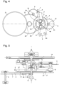
- FIG 5 shows a cross-section from bottom to top of the mechanism in the centre of the tourbillon as partly shown above with reference to the figure 1 or to the figure 2 . It is especially noticeable in this figure that the second pinion 5 is the axis of the tourbillon cage 15.
- the fixed second wheel SFA pivots concentrically to the tourbillon axis without touching it thanks to the flexible blade guide system holding it in position.
- the tourbillon cage 15 encloses the escapement mechanism with the escapement wheel 11, the Swiss anchor 13 and in connection with the oscillator 14 which is the balance spring.
- the fixed seconds wheel SFA 2 meshes with the escapement pinion 12, which means that when the tourbillon cage 15 rotates every second, a rotation is also carried out for the escapement mechanism linked to the oscillator and also the fixed seconds wheel SFA 2.
- the flexible guide 4 is fixed to the fixed second wheel SFA 2.
- at least one fixing means 27 in or through the openings 17 is thus provided to fix the fixed second wheel SFA 2 on the movable portion of the flexible guide 4 as previously indicated.
- These fixing means 27 are preferably material extensions of central portions of the second wheel 2 so as to be force-fitted into the openings 17 of the flexible guide 4.
- These material extensions 27, as well as a border around these material extensions, come directly from the material precisely with the rest of the second wheel to form only one piece.
- a finger-shaped edge portion 3b of the rake 3 is freely disposed inside a guide housing between two teeth of a cam 6 visible at figure 2 . Since the cam 6 is fixed integrally with said fixed second wheel SFA 2 near its center, this makes it possible to drive in rotation the rack 3, which on the other hand comprises the blocking pallet 3a for blocking the whip 7 in a stop mode.
- the whip 7 further comprises an axial blocking pinion 8, which can be rotated upon release of the whip 7 in the jump mode. All the other elements have already been explained above and will not be repeated again.
- the mechanical movement can be a traditional mechanical movement with a fixed second wheel SFA also connected to drive or maintain the escape wheel with the oscillator in a stop phase.
Landscapes
- Physics & Mathematics (AREA)
- General Physics & Mathematics (AREA)
- Micromachines (AREA)
- Transmission Devices (AREA)
- Electromechanical Clocks (AREA)
Description
L'invention concerne une montre à mouvement mécanique à mécanisme de contrôle de force, telle que la force due à la gravité lors du porter de la montre et du type à seconde sautante. De préférence, le mécanisme de contrôle de force peut être un mécanisme à tourbillon monté au niveau de l'échappement. La cage du tourbillon entoure le mécanisme d'échappement et de préférence la cage effectue une rotation complète chaque minute avec notamment 60 sauts de seconde effectués.The invention relates to a mechanical movement watch with a force control mechanism, such as the force due to gravity when wearing the watch and of the jumping second type. Preferably, the force control mechanism may be a tourbillon mechanism mounted at the escapement. The tourbillon cage surrounds the escapement mechanism and preferably the cage makes a complete rotation every minute with in particular 60 jumps of a second made.
A titre de rappel en horlogerie, un tourbillon, également appelé « cage tournante », est une complication horlogère, ajoutée au mécanisme d'échappement, destinée à améliorer la précision des montres mécaniques en contrebalançant les perturbations de l'isochronisme du résonateur dues à la gravité terrestre. Le critère fondamental, qui signe un tourbillon, par rapport à un carrousel notamment, est la présence d'un rouage fixe sur lequel engrène la cage du tourbillon. Généralement, la cage du tourbillon est montée rotative entre deux points de fixation.As a reminder in watchmaking, a tourbillon, also called a "rotating cage", is a watch complication, added to the escapement mechanism, intended to improve the precision of mechanical watches by counterbalancing the disturbances of the isochronism of the resonator due to the Earth's gravity. The fundamental criterion, which marks a tourbillon, in comparison with a carousel in particular, is the presence of a fixed gear train on which the tourbillon cage meshes. Generally, the tourbillon cage is rotatably mounted between two fixing points.
Il est tenu compte également de la gravité pour compenser toutes les perturbations de l'isochronisme du résonateur. L'échappement est couplé au résonateur. Il interagit avec celui-ci une ou deux fois par période d'oscillation. L'angle parcouru par le résonateur pendant l'interaction est appelé angle de levée. Le reste du parcours du résonateur est appelé angle ou arc supplémentaire.Gravity is also taken into account to compensate for any disturbances in the isochronism of the resonator. The escapement is coupled to the resonator. It interacts with it once or twice per oscillation period. The angle traveled by the resonator during the interaction is called the lift angle. The rest of the resonator's path is called the additional angle or arc.
Pendant l'angle supplémentaire, le résonateur peut être en contact avec l'échappement (échappement à repos frottant) ou sans contact (échappement libre). Pendant l'angle de levée, l'échappement exécute deux phases principales, qui sont le dégagement (ou comptage) et l'impulsion (ou entretien).During the additional angle, the resonator can be in contact with the escapement (rubbing rest escapement) or without contact (free escapement). During the lift angle, the escapement performs two main phases, which are the release (or counting) and the impulse (or maintenance).
Dans une complication horlogère, la seconde sautante a pour but d'afficher la seconde par pas d'une seconde entière, ce qui correspond sur un cadran de 60 secondes à 6° d'angle par seconde. Cette seconde sautante est souvent associée à des mécanismes de force constante qui profitent de la particularité de construction de cette seconde sautante. Des mécanismes de seconde morte ou de seconde fixe s'approchent aussi de ces constructions avec la particularité de pouvoir arrêter la seconde à volonté comme un chronographe.In a watch complication, the jumping second is intended to display the second in steps of a whole second, which corresponds on a 60-second dial to 6° of angle per second. This jumping second is often associated with constant force mechanisms that take advantage of the particular construction of this jumping second. Dead second or fixed second mechanisms also approach these constructions with the particularity of being able to stop the second at will like a chronograph.
Plusieurs mécanismes de seconde sautante existent dans la littérature horlogère et les brevets, et sont appliqués. Selon certains exemples, dans une montre Jacquet Droz, il y a le mouvement 1195 de Blancpain. Pour la Marie Antoinette de Breguet, il y a le mécanisme avec la seconde morte.Several jumping second mechanisms exist in watch literature and patents, and are applied. According to some examples, in a Jacquet Droz watch, there is the Blancpain 1195 movement. For the Breguet Marie Antoinette, there is the mechanism with the dead second.
Dans la demande de
Le principe de ces mécanismes décrits est de retenir le rouage de finissage entre l'échappement et la seconde par un mécanisme, alors qu'un ressort annexe entretient l'échappement avec une force constante dans une phase d'arrêt. Au terme de la seconde, qui est comptée par l'échappement, le rouage libéré permet d'effectuer l'avance d'une seconde. Ainsi l'affichage avance de ce fait et le mécanisme est réarmé en phase de saut.The principle of these mechanisms described is to retain the gear train between the escapement and the second by a mechanism, while an auxiliary spring maintains the escapement with a constant force in a stopping phase. At the end of the second, which is counted by the escapement, the released gear train allows the advancement of one second. Thus the display advances as a result and the mechanism is rearmed in the jump phase.
Dans un tel mécanisme fonctionnant à des fréquences proches de la seconde, les couples disponibles en horlogerie sont très faibles. C'est pourquoi ces mécanismes sont difficiles à réaliser et en général peu fiables.In such a mechanism operating at frequencies close to the second, the torques available in watchmaking are very low. This is why these mechanisms are difficult to produce and generally unreliable.
Dans le mécanisme du mouvement 1195 de Blancpain, il y a un système d'arrêt qui distribue une partie de couple dans le blocage de la phase d'arrêt pour compenser les frottements. Cela donne une seconde sautante ayant un déplacement angulaire d'environ 20 % dans la phase d'arrêt pour un saut de 80 %.In the mechanism of the Blancpain 1195 movement, there is a stop system that distributes part of the torque in the blocking of the stop phase to compensate for friction. This gives a jumping second with an angular displacement of about 20% in the stop phase for an 80% jump.
Il peut aussi être envisagé de diminuer la fréquence et de réaliser des minutes mortes au lieu de seconde, ce qui facilite la construction.It can also be considered to reduce the frequency and to make dead minutes instead of seconds, which facilitates the construction.
Certains de ces mécanismes peuvent se désynchroniser après un désarmage complet, et se mettre en position de blocage. Cela nécessite un système d'arrêt lié à un mécanisme de réserve de marche, qui arrêtera le mécanisme avant le désarmage complet.Some of these mechanisms can become desynchronized after complete disarming, and go into a blocking position. This requires a stop system linked to a power reserve mechanism, which will stop the mechanism before complete disarming.
Dans un mécanisme décrit dans le
Le modèle d'utilité
Le
Le document
Pour la présente invention, il est recherché de réaliser un affichage de seconde sautante et encore de force constante de manière plus simple, sans déplacement de mobile et sans risque de désynchronisation en fin d'armage et limitant ainsi les frottements pour une utilisation notamment dans un mouvement à tourbillon.For the present invention, it is sought to produce a jumping second display and also a constant force display in a simpler manner, without moving the mobile and without risk of desynchronization at the end of winding and thus limiting friction for use in particular in a tourbillon movement.
L'invention a donc pour but de pallier les inconvénients de l'état de la technique en fournissant une montre à mouvement mécanique à mécanisme de compensation ou de contrôle de force du type à seconde sautante palliant les inconvénients des dispositifs de l'art antérieur susmentionnés.The invention therefore aims to overcome the drawbacks of the state of the art by providing a watch with a mechanical movement with a force compensation or control mechanism of the jumping second type, overcoming the drawbacks of the aforementioned prior art devices.
A cet effet, l'invention concerne une montre à mouvement mécanique à mécanisme de compensation ou de contrôle de force du type à seconde sautante, qui comprend les caractéristiques définies dans la revendication indépendante 1.For this purpose, the invention relates to a watch with a mechanical movement with a force compensation or control mechanism of the second type. jumping, which includes the features defined in
Des formes particulières de réalisation de la montre à mouvement mécanique à mécanisme de compensation ou contrôle de force du type à seconde sautante sont décrites également dans les revendications dépendantes 2 à 18.Particular embodiments of the watch with mechanical movement with compensation mechanism or force control of the jumping second type are also described in
Un avantage de la montre à mouvement mécanique à mécanisme de contrôle de force selon l'invention réside dans le fait qu'il comprend une roue de seconde pour accumuler l'énergie nécessaire à entretenir plusieurs oscillations du mécanisme d'échappement avec l'oscillateur, notamment dans un mode d'arrêt avant le passage dans un mode de saut. En fonction de la fréquence du résonateur muni d'un échappement traditionnel, la roue de seconde entretient quelques oscillations du résonateur ou oscillateur sans qu'une partie du rouage venant du barillet ne soit entraîné. De préférence, la roue de seconde libère un élément de blocage, tel qu'un fouet après un certain nombre d'oscillations pour faire déplacer notamment la cage du tourbillon de 6° dans le sens des aiguilles d'une montre (SAM) et le rouage de finissage venant du barillet définissant une roue de seconde du type à seconde sautante. Dans le cas du tourbillon selon un exemple de réalisation à au moins la cinquième impulsion de l'oscillateur de 2.5 Hz, le fouet est libéré et par lui, la roue intermédiaire liée au fouet, la roue moyenne, la roue grande moyenne et le barillet pour entraîner la cage du tourbillon d'un pas de 6° dans une direction opposée à l'accumulation de la roue de seconde. Principalement, la cage du tourbillon peut être déplacée angulairement après un certain nombre d'oscillations définissant une seconde. Par cet agencement sans déplacement de mobile, le risque de désynchronisation à la fin de l'armage n'est pas affecté.An advantage of the mechanical movement watch with a force control mechanism according to the invention lies in the fact that it comprises a second wheel for accumulating the energy necessary to maintain several oscillations of the escapement mechanism with the oscillator, in particular in a stop mode before switching to a jump mode. Depending on the frequency of the resonator equipped with a traditional escapement, the second wheel maintains a few oscillations of the resonator or oscillator without part of the gear train coming from the barrel being driven. Preferably, the second wheel releases a blocking element, such as a whip after a certain number of oscillations to move in particular the tourbillon cage by 6° in the clockwise direction (SAM) and the finishing gear train coming from the barrel defining a second wheel of the jumping second type. In the case of the tourbillon according to an exemplary embodiment at least at the fifth pulse of the 2.5 Hz oscillator, the whip is released and by it, the intermediate wheel linked to the whip, the medium wheel, the large medium wheel and the barrel to drive the tourbillon cage by a step of 6° in a direction opposite to the accumulation of the second wheel. Mainly, the tourbillon cage can be moved angularly after a certain number of oscillations defining a second. By this arrangement without moving the mobile, the risk of desynchronization at the end of winding is not affected.
Avantageusement, la roue de seconde est destinée à bouger en phase d'arrêt d'un certain nombre de petits pas suite aux oscillations du ressort spiral de l'oscillateur lié au mécanisme d'échappement, qui est du type à ancre suisse. Dans cette phase d'arrêt ou mode d'arrêt, la roue de seconde tourne dans le sens contraire des aiguilles d'une montre en étant entraînée en rotation par un guidage flexible à lames élastiques, qui est pré-armé. Une portion mobile de ce guidage flexible est fixée sur une face de la roue de seconde, alors qu'une portion fixe de ce guidage flexible est fixée sur un support du mouvement horloger, tel qu'une platine. La portion mobile de ce guidage flexible est de préférence fixée directement en dessous de la roue de seconde. Le guidage flexible est monté par une ouverture axiale, de manière coaxiale à un pignon de seconde, qui est le pignon de seconde et de tourbillon.Advantageously, the second wheel is intended to move in the stop phase by a certain number of small steps following the oscillations of the spiral spring of the oscillator linked to the escapement mechanism, which is of the Swiss anchor type. In this stop phase or stop mode, the second wheel second rotates counterclockwise while being rotated by a flexible guide with elastic blades, which is pre-wound. A movable portion of this flexible guide is fixed on a face of the second wheel, while a fixed portion of this flexible guide is fixed on a support of the watch movement, such as a plate. The movable portion of this flexible guide is preferably fixed directly below the second wheel. The flexible guide is mounted by an axial opening, coaxially with a second pinion, which is the second and tourbillon pinion.
Avantageusement, le guidage flexible à lames élastiques (lames ressort) comprend plusieurs lames élastiques en série reliant des parties plus massives dont les portions mobile et fixe du guidage flexible, et éventuellement d'autres portions intermédiaires. Le guidage flexible à lames élastiques en série peut ainsi être réalisé avec une structure plus robuste capable d'assurer la rotation de la roue de seconde avec un couple de rappel utilisé avantageusement pour remplacer le ressort du mécanisme de contrôle de force et avec un meilleur maintien axial. De plus, un tel guidage flexible à lames élastiques permet d'avoir une absence de frottement, d'usure et de dissipation d'énergie, ainsi qu'une absence de jeu et un guidage précis.Advantageously, the flexible guide with elastic blades (spring blades) comprises several elastic blades in series connecting more massive parts including the mobile and fixed portions of the flexible guide, and possibly other intermediate portions. The flexible guide with elastic blades in series can thus be produced with a more robust structure capable of ensuring the rotation of the second wheel with a return torque advantageously used to replace the spring of the force control mechanism and with better axial support. In addition, such a flexible guide with elastic blades makes it possible to have an absence of friction, wear and energy dissipation, as well as an absence of play and precise guidance.
Les buts, avantages et caractéristiques de la montre à mouvement mécanique à mécanisme de compensation ou contrôle de force apparaîtront mieux dans la description suivante notamment en regard des dessins sur lesquels :
- la
figure 1 représente une vue tridimensionnelle depuis dessous des principaux éléments du mouvement de montre à mécanisme de contrôle de force et du type à seconde sautante selon l'invention, - la
figure 2 représente une vue de dessous du mouvement de montre mécanique à mécanisme de contrôle de force du type à seconde sautante sans la roue moyenne et la roue intermédiaire selon l'invention, - les
figures 3a, 3b et 3c représentent des vues en plan de trois formes d'exécution de guidages flexibles à lames élastiques ou pivots à lames flexibles à couples plus élevés et meilleur maintien axial pour pouvoir être reliés à la roue de seconde selon l'invention, - la
figure 4 représente une vue depuis dessous d'une autre forme d'exécution schématique d'un mouvement mécanique traditionnel de montre avec le rouage de finissage sans tourbillon et le mécanisme de contrôle de force selon l'invention, et - la
figure 5 représente une coupe transversale de bas en haut du mécanisme au centre du tourbillon comme représenté ci-dessus partiellement à lafigure 1 .
- there
figure 1 represents a three-dimensional view from below of the main elements of the watch movement with force control mechanism and jumping second type according to the invention, - there
figure 2 represents a bottom view of the mechanical watch movement with force control mechanism of the jumping second type without the middle wheel and the intermediate wheel according to the invention, - THE
Figures 3a, 3b and 3c represent plan views of three embodiments of flexible guides with elastic blades or pivots with flexible blades with higher torques and better axial support to be able to be connected to the second wheel according to the invention, - there
figure 4 represents a view from below of another schematic embodiment of a traditional mechanical watch movement with the non-tourbillon finishing train and the force control mechanism according to the invention, and - there
figure 5 represents a cross-section from bottom to top of the mechanism in the center of the tourbillon as shown above partially at thefigure 1 .
Dans la description suivante, différents organes ou éléments du mouvement mécanique de montre à mécanisme de contrôle de force et du type à seconde sautante, qui sont bien connus dans ce domaine technique, ne seront décrits que sommairement.In the following description, various organs or elements of the mechanical watch movement with force control mechanism and of the jumping second type, which are well known in this technical field, will only be described briefly.
Il est tout d'abord à noter que la montre à mouvement mécanique à mécanisme de contrôle de force et du type à seconde sautante peut être avec un tourbillon dont la cage enferme un oscillateur et un mécanisme d'échappement comme expliqué ci-après, ou selon un mouvement mécanique traditionnel sans tourbillon, qui sera expliqué par la suite en référence à la
Les
Les
Le mobile d'échappement 11 engrène avec une roue de seconde 2 qui est définie par la suite aussi comme une roue de seconde fixe SFA. Cette roue de seconde 2 est appelée une roue de seconde fixe SFA, même si elle n'est pas fixe dans son fonctionnement. Cette roue de seconde fixe SFA 2 peut tourner dans le sens inverse des aiguilles d'une montre (SIAM) pour entretenir le fonctionnement du mécanisme d'échappement lié à l'oscillateur dans un mode d'arrêt, et tourner dans le sens des aiguilles d'une montre (SAM) dans un mode de saut pour effectuer un saut correspondant à 1 seconde. Aussi bien dans la forme d'exécution avec un tourbillon, que dans la forme d'exécution sans tourbillon, il y a toujours une phase d'arrêt et une phase de saut de manière à faire un saut sur l'affichage correspondant à une seconde.The
Pour ce faire, la roue de seconde fixe SFA 2 comporte de préférence une denture en périphérie engrenant avec un pignon denté d'échappement 12 coaxial audit mobile d'échappement 11. Comme expliqué ci-après dans une phase d'arrêt du rouage de finissage, la roue de seconde fixe SFA 2 tourne en sens inverse des aiguilles de la montre (SIAM) par la force de rappel du guidage flexible 4 et entraîne le mobile d'échappement 11 à chaque demi-oscillation de l'oscillateur 14 par l'intermédiaire du pignon denté d'échappement 12 de manière à entretenir le fonctionnement de l'oscillateur et du mécanisme d'échappement dans cette phase d'arrêt.To do this, the fixed
Pendant cette phase d'arrêt, la roue de seconde fixe SFA 2 pivote en SIAM sur son guidage flexible 4 autour de la cage 15 du tourbillon sans toucher celle-ci, qui est arrêtée. Ce pivotement SIAM de la SFA 2 s'effectue jusqu'au moment de la libération du rouage de finissage 5, 8, 9, 10 par lequel un saut d'une seconde est effectué par la cage 15 de tourbillon et son pignon de seconde 5, entraînant avec lui la roue de seconde fixe SFA 2, qui est liée au mobile d'échappement 11, dans la phase de saut dans le sens des aiguilles d'une montre SAM.During this stopping phase, the fixed seconds wheel
Pour définir la phase d'arrêt et la phase de saut, le mécanisme de contrôle de force comprend d'une part un élément de blocage rotatif 7 agencé pour coopérer avec un organe d'arrêt 3 en liaison avec la roue de seconde fixe SFA 2 dans le mode d'arrêt. Comme illustré aux
Pour entraîner en rotation la roue de seconde fixe SFA 2 notamment dans un mode d'arrêt, un guidage flexible 4 à lames élastiques 4a ou lames ressort, qui est pré-armé, est relié directement à la roue de seconde fixe SFA 2. Le guidage flexible 4 agit comme un ressort sur la roue de seconde fixe SFA 2. Pour ce faire, le guidage flexible 4 comprend une portion mobile 4c avec au moins une ouverture 17 mais de préférence deux ouvertures 17 pour la fixation sur une face de la roue de seconde fixe SFA 2. De préférence, le guidage flexible 4 est fixé sur une face inférieure de la roue de seconde fixe SFA 2.To drive the fixed
Il est à noter qu'il est défini des lames élastiques 4a, ces lames peuvent être de section transversale rectangulaire, hexagonale, voire ronde. Ces lames élastiques ont une géométrie : longueur et section qui doit être bien déterminée pour assurer la fonction ressort pour entraîner en rotation la roue de seconde fixe SFA 2 avec le couple nécessaire. On peut se référer à l'ouvrage W. H. Wittrick indiqué ci-après, pour la réalisation des guidages flexibles 4 à lames élastiques 4a.It should be noted that
Comme représenté à la
Le guidage flexible 4 comprend encore une portion fixe 4b avec au moins une ouverture 16, mais de préférence deux ouvertures 16 pour être montée et fixée par l'intermédiaire d'un ensemble vis et écrou non représentés sur un support du mouvement horloger, tel qu'une platine. Plusieurs lames élastiques 4a ou portions de lames élastiques relient la portion mobile 4c à la portion fixe 4b ainsi que des portions intermédiaires éventuellement entre les portions mobile 4c et fixe 4b. Le guidage flexible 4 est monté par une ouverture axiale, de manière coaxiale au pignon de seconde 5, et autour d'un tube axial de la roue de seconde fixe SFA 2 coaxiale à l'axe du pignon de seconde 5.The
Il est à noter encore qu'il peut être envisagé d'avoir deux ouvertures de fixation prévues dans la roue de seconde fixe SFA 2 pour recevoir par insertion à force deux prolongements de matière de la portion mobile 4c du guidage flexible 4 de manière équivalente mais inversement à ce qui a été décrit ci-dessus. Le moyen de fixation peut aussi être un ensemble vis et écrou passant par des ouvertures de la portion mobile et de la roue de seconde fixe SFA 2, mais avec ce type de montage, trop d'espace est gaspillé. De même, la fixation de la portion fixe 4b du guidage flexible 4 sur la platine peut être effectuée par un autre moyen que l'ensemble vis et écrou, en prenant exemple de la fixation de la roue de seconde fixe SFA 2 sur le guidage flexible 4. En position de repos c'est-à-dire dès le passage du mode de saut au mode d'arrêt, les lames élastiques 4a du guidage flexible 4 doivent être précontraintes pour accumuler une énergie mécanique pour faire tourner la roue de seconde fixe SFA 2 en particulier dans le sens contraire des aiguilles d'une montre (SIAM).It should also be noted that it may be envisaged to have two fixing openings provided in the fixed
La rotation de la roue de seconde fixe SFA 2 entraîne également le mobile d'échappement 11 par l'intermédiaire d'un pignon d'échappement 12 coaxial du mobile d'échappement du mécanisme d'échappement à ancre suisse 13. Ceci est avantageux pour maintenir en fonction le mécanisme d'échappement avec l'oscillateur 14 dans cette phase d'arrêt par l'énergie mécanique accumulée dans le guidage flexible 4 à lames élastiques 4a agissant sur la roue de seconde fixe SFA 2 pour la faire tourner dans un sens inverse des aiguilles d'une montre (SIAM).The rotation of the fixed
Le râteau 3 est relié sans l'action d'un ressort à une came 6 fixée sur la roue de seconde fixe SFA 2 pour bloquer ou libérer ledit rouage de finissage selon la position angulaire de ladite roue de seconde fixe SFA 2 par la retenue d'un fouet 7, comme élément de blocage. Ce fouet 7 vient en contact d'une pièce d'arrêt 3a de la partie de blocage du râteau 3. Cette pièce d'arrêt est une palette 3a, comme décrit ci-dessus.The
Dans le cas de figure présenté, la roue de seconde fixe SFA 2 peut tourner de 5 petits pas correspondant à 6° d'angle représentant 1 seconde en sens inverse. Le fouet 7 est lui-même entraîné par le rouage de finissage et retenu par la pièce d'arrêt 3a. Une fois libéré à la fin de la phase d'arrêt, la rotation du râteau 3 libère le fouet 7 qui déclenche la phase de saut. Pendant la phase de saut, le fouet 7 effectue une rotation correspondant à un saut de 1 seconde, entraîné par le rouage de finissage, dans le cas représenté, un demi-tour. Le rouage de finissage entraîne de même la cage 15 de tourbillon par le pignon de seconde 5 et la roue de seconde fixe SFA 2 dans le sens des aiguilles d'une montre (SAM), ce qui réarme le guidage flexible 4. Ce guidage flexible 4 de la roue de seconde fixe SFA 2 est agencé pour accumuler de l'énergie lorsque ladite roue de seconde fixe SFA 2 est entraînée en SAM pendant la phase de saut et la restituer à ladite roue de seconde fixe SFA 2 en SIAM pendant la phase d'arrêt.In the case shown, the fixed
Généralement dans la phase d'arrêt, plusieurs demi-oscillations de l'oscillateur 14 interviennent avant la libération du rouage de finissage. Cela signifie que la fréquence de l'oscillateur 14 est généralement plus élevée que 1 Hz et par exemple dans ce cas présent, peut être établi à 2.5 Hz. Comme la roue de seconde fixe SFA 2 tourne dans la phase d'arrêt à chaque petit pas correspondant à une demi-oscillation (alternance), on peut compter 5 demi-oscillations de l'oscillateur 14 dans la phase d'arrêt jusqu'au moment de la libération de l'élément de blocage rotatif 7 pour la phase de saut. Le guidage flexible 4 lié à la roue de seconde fixe SFA 2 doit donc fournir de l'énergie pendant les 5 demi-oscillations de l'oscillateur 14 ou la cage est arrêtée, et être réarmé pendant le saut de ladite cage 15.Typically in the stopping phase, several half-oscillations of the
Le guidage flexible 4 représenté sur la
Dans cette forme d'exécution, cinq lames élastiques 4a successives relient un premier côté intérieur de la portion mobile 4c à un premier côté intérieur de la portion fixe 4b. Une première lame élastique 4a depuis la portion mobile 4c est reliée à une première portion centrale intermédiaire. Une seconde lame élastique 4a depuis la première portion centrale intermédiaire est reliée à une première portion périphérique intermédiaire. Une troisième lame élastique 4a depuis la première portion périphérique intermédiaire est reliée à une seconde portion centrale intermédiaire. Une quatrième lame élastique 4a depuis la seconde portion centrale intermédiaire est reliée à une seconde portion périphérique intermédiaire. Une cinquième lame élastique depuis la seconde portion périphérique intermédiaire est reliée à un premier côté intérieur de la portion fixe 4b.In this embodiment, five successive
Cinq lames élastiques 4a successives relient un second côté intérieur de la portion mobile 4c à un second côté intérieur de la portion fixe 4b. Une seconde lame élastique 4a depuis la portion mobile 4c est reliée à la même première portion centrale intermédiaire. Une seconde lame élastique 4a depuis la même première portion centrale intermédiaire est reliée à la même première portion périphérique intermédiaire. Une troisième lame élastique 4a depuis la première portion périphérique intermédiaire est reliée à la même seconde portion centrale intermédiaire. Une quatrième lame élastique 4a depuis la seconde portion centrale intermédiaire est reliée à la même seconde portion périphérique intermédiaire. Une cinquième lame élastique depuis la seconde portion périphérique intermédiaire est reliée à un premier côté intérieur de la portion fixe 4b.Five successive
On constate que la partie fixe 4b est disposée à l'intérieur entre la portion mobile 4c et les deux portions périphériques intermédiaires. De plus, les deux portions centrales intermédiaires forment un arc de cercle centré sur l'axe du pignon de seconde 5, et il en est de même pour les deux portions périphériques intermédiaires également centrées sur l'axe du pignon de seconde 5.It is noted that the
Cependant, il peut être prévu plus ou moins de demi-oscillations de l'oscillateur 14 dans la phase d'arrêt fonction de la fréquence d'oscillation de l'oscillateur 14. Chaque demi-oscillation doit être égale à 0.2 s pour un oscillateur de 2.5 Hz. Le nombre n de demi-oscillations de l'oscillateur peut donc être choisi que pour une fréquence de l'oscillateur supérieure à 1 Hz, par exemple pour au moins n = 3 demi-oscillations pour 1.5Hz ou n = 5 pour 2.5Hz. Le nombre de petits pas effectués par la roue de seconde fixe SFA 2 en phase d'arrêt doit correspondre à un saut de 1 seconde en phase de saut.However, more or less half-oscillations of the
Il peut aussi être envisagé de faire des sauts de période plus grande que 1 seconde, ce qui généralise la règle ci-dessus à une fréquence d'oscillateur supérieure à la fréquence des sauts d'affichage. De cette manière, il pourrait être envisagé de sauter toutes les minutes.It could also be considered to make jumps of period greater than 1 second, which generalizes the above rule to an oscillator frequency higher than the display jump frequency. In this way, it could be considered to jump every minute.
En référence à la forme d'exécution présentée aux
La palette 3a est agencée pour coopérer en appui avec ledit élément de blocage 7, qui est un fouet, pour bloquer ledit rouage de finissage dans une phase d'arrêt, ou pour libérer ledit élément de blocage 7 et ledit rouage de finissage dans une phase de saut. Le fouet 7 comprend une première partie de tige de blocage et une seconde partie de tige de blocage par rapport à son centre qui comprend le pignon axial de blocage 8. Une fois que la palette 3a n'est plus en contact avec la première partie de tige du fouet 7 ou la seconde partie de tige du fouet 7, dans la phase de saut, le fouet 7 est mis en rotation et tourne sur 180° pour permettre la rotation du rouage de finissage avant une nouvelle position de blocage du rouage de finissage dans un mode d'arrêt. Dans le mode de saut, la cage 15 du tourbillon est entraînée en rotation de 6° dans le sens des aiguilles d'une montre (SAM) par le rouage de finissage pour ajouter une seconde au temps. La roue de seconde fixe SFA 2 est entraînée avec la cage 15, qui est liée au pignon de seconde coaxial 5 de 6° d'angle pour réarmer le guidage flexible 4 du râteau SFA. La roue de seconde fixe SFA 2 est entraînée par la cage 15, car le mécanisme d'échappement tourne également avec la cage. Le réarmage du guidage flexible 4 s'effectue rapidement, ce qui fait que l'extrémité du fouet 7 revient directement en contact de la palette d'arrêt 3a une fois que le fouet 7 a tourné de 180°. Dès ce nouveau blocage, une nouvelle opération de phase d'arrêt intervient.The
On comprend que la rotation de 180° du fouet 7 avant un nouvel arrêt est directement et dynamiquement liée aux inerties des composants en mouvement. En particulier l'inertie du fouet 7, qui a la rotation la plus rapide, à une grande importance. On préférera donc une construction du fouet 7 favorisant une inertie faible, telle qu'elle peut être obtenue avec les moyens de fabrication LIGA en Nickel ou Nickel Phosphore ou les moyens de fabrication DRIE en silicium. Ces moyens de fabrication permettent la réalisation de fouet 7 de géométrie précise et avantageuse pour limiter l'inertie du fouet 7.It is understood that the 180° rotation of the
Pendant la phase d'arrêt, le mobile d'échappement 11 est entraîné dans un premier sens de rotation (SIAM) par la roue de seconde fixe SFA 2, ce qui correspond à chaque demi-oscillation de l'oscillateur 14 entretenu. 5 petits pas sont effectués par le mobile d'échappement 11 entraîné en rotation par la roue de seconde fixe SFA 2 et par l'intermédiaire du pignon d'échappement 12. Cela désarme ledit guidage flexible 4 qui entraîne la roue de seconde fixe SFA 2 et déplace ladite palette 3a dans le sens de la libération du fouet 7.During the stop phase, the
Comme le rouage de finissage est bloqué dans le mode d'arrêt à l'exception de la roue de seconde fixe SFA 2, le guidage flexible 4 lié à la roue de seconde fixe SFA 2 libère de l'énergie pour faire tourner ladite roue de seconde fixe SFA 2 pour entraîner le mobile d'échappement 11. Dans le mode de saut, dès que le fouet 7 n'est plus en contact avec la palette 3a, le rouage de finissage par l'intermédiaire du pignon axial de blocage 8 du fouet 7, est agencé pour faire pivoter par l'intermédiaire du pignon de seconde 5 et de la cage 15 de tourbillon, ladite roue de seconde fixe SFA 2. Cette roue de seconde fixe SFA 2 avec la cage 15 de tourbillon tournent de 6° d'angle dans un deuxième sens de rotation, qui est le sens des aiguilles d'une montre (SAM) opposé audit premier sens de rotation imposé au mobile d'échappement 11 par la roue de seconde fixe SFA 2, selon une course correspondant à un saut angulaire d'une seconde. La cage 15 du tourbillon est pivotée de 6° d'angle dans le mode de saut dans le sens des aiguilles d'une montre (SAM) dans une direction opposée au pivotement de la roue de seconde fixe SFA 2 dans la phase d'arrêt. Au terme du saut, le fouet 7 revient en appui contre la palette 3a pour bloquer à nouveau le rouage de finissage à l'exception de la roue de seconde fixe SFA 2. Le fouet 7 avec ses deux parties de tige de même longueur fait une rotation de 180° pour passer du mode de saut au mode d'arrêt suivant.Since the finishing gear is blocked in the stop mode with the exception of the fixed
Il est à noter que le fouet 7 est lié au rouage de finissage et au barillet par la roue intermédiaire 9 pour le faire tourner autour de son axe central à chaque mode de saut de 1 seconde et pour libérer le rouage de finissage 5, 8, 9, 10, ainsi que la cage 15 du tourbillon dans cette forme d'exécution. La force du ou des ressorts d'entraînement du rouage de finissage est supérieure à l'énergie mécanique accumulée dans le guidage flexible 4. Ainsi, le rouage de finissage est immédiatement mis en fonction dès sa libération ce qui permet de garder un bon synchronisme dans le temps, étant donné également que le mécanisme d'échappement et l'oscillateur 14 sont maintenus en fonction pendant la phase d'arrêt même si le rouage de finissage est bloqué excepté la roue de seconde fixe SFA 2.It should be noted that the
Tous les éléments du mécanisme de contrôle de force décrits ci-dessus sont montés sur une platine, un pont de moyenne, un pont de fouet, qui ne sont pas représentés pour ne pas surcharger les dessins.All the elements of the force control mechanism described above are mounted on a plate, a mean bridge, a whip bridge, which are not shown so as not to overload the drawings.
Comme déjà mentionné ci-dessus, la roue de seconde fixe SFA 2 comporte une denture en périphérie engrenant avec le pignon denté d'échappement 12 coaxial au mobile d'échappement 11. Une roue moyenne 10, que comporte le rouage de finissage, a une denture en périphérie engrenant avec le pignon denté axial de seconde 5 coaxial à la roue de seconde fixe SFA 2, et dont l'axe du pignon de seconde 5 est relié à la cage 15 de tourbillon. Une roue intermédiaire 9, que comporte également ledit rouage de finissage, comporte un pignon denté axial intermédiaire 19 engrenant avec la denture en périphérie de la roue moyenne 10. La roue intermédiaire 9 comporte une denture en périphérie pour engrener avec ledit pignon axial de blocage 8 solidaire de l'élément de blocage rotatif 7, qui est le fouet. Dans la phase de saut lors de la libération dudit rouage de finissage, le pignon denté axial intermédiaire 19 est agencé pour laisser tourner la roue moyenne 10, pour lui permettre de faire pivoter la cage de tourbillon 15 par l'intermédiaire du pignon de seconde 5 dans ledit deuxième sens de rotation SAM. Dans ce deuxième sens de rotation le pignon de seconde 5 fournit l'énergie à accumuler dans le guidage flexible 4 en faisant tourner la roue de seconde fixe SFA 2 en SAM.As already mentioned above, the fixed
Pour déterminer certaines valeurs dimensionnelles en fonction des éléments décrits ci-dessus on peut mentionner que le verrouillage se fait par un rouage depuis la moyenne 10 et cun fouet 7 de grand diamètre. Cela permet de limiter le déplacement pendant la seconde, de limiter les frottements, et sortir le pivotement du fouet 7 de la surface occupée par la cage de tourbillon sur la platine.To determine some dimensional values based on the elements described above, it can be mentioned that the locking is done by a gear train from the average 10 and a
Le rapport important entre moyenne 0.116 t/min et le fouet 0.5 t/sec (30 t/min) demande un mobile intermédiaire, qui est la roue intermédiaire 9. Cela donne par exemple un rapport roue moyenne 10 et roue intermédiaire 9 à Z = 120/7 et m = 0.07 mm, et un rapport roue intermédiaire 9 et fouet 7 à Z = 90/6 et m = 0.07 mm.The high ratio between average 0.116 rpm and whip 0.5 rpm (30 rpm) requires an intermediate wheel, which is
Selon une version alternative, il est possible d'entraîner le fouet 7 depuis la cage 15 de tourbillon directement. Cela demande de réaliser une cage de tourbillon avec une denture extérieure en prise avec le pignon axial de blocage 8, qui est le pignon de fouet. Le rapport entre la cage 15 et le fouet 7 est 1 t/min et fouet 0.5 t/sec (30 t/min), peut se faire avec un rouage direct. Le rapport denture extérieur du tourbillon au pignon de fouet est Z = 180/6 avec m = 0.079 mm avec une position du fouet identique à celle de la version précédente. Cependant l'esthétisme de la cage de tourbillon est pénalisé par cette denture extérieure.According to an alternative version, it is possible to drive the
La prise de repos (phase d'arrêt) sur la palette 3a du râteau 3 est de 0.08 mm, ce qui est confortable pour une ancre d'échappement, mais probablement un peu faible en regard de la longueur du râteau. La construction peut facilement gagner 25 % en augmentant le rayon de travail de la palette 3a. De toute façon, l'augmentation de déplacement (pour la sécurité) sur la palette 3a augmente les risques liés aux frottements.The resting point (stopping phase) on
A titre de rappel en référence par exemple à la
Les
Sur la
Sur la
Finalement sur la
Il est clair que le type de matériaux choisis pour réaliser ces guidages flexibles 4 sont des matériaux utilisés pour réaliser des ressorts métalliques. Dans les différentes variantes de guidage flexible 4 décrit ci-dessus, chaque guidage flexible 4 peut être sous la forme d'une plaque plane, dans l'épaisseur peut être choisie sensiblement équivalente à l'épaisseur de la portion centrale de la roue de seconde fixe SFA 2.It is clear that the type of materials chosen to make these
La
Dans cette forme d'exécution, on peut à nouveau spécifier les deux phases, qui sont d'une part la phase d'arrêt et d'autre part la phase de saut. Dans la phase d'arrêt, le rouage de finissage 5, 8, 9, 10 est verrouillé par l'appui d'une dent de l'élément de blocage 7 contre l'organe d'arrêt 3. Le mobile d'échappement 11 est entraîné par la roue de seconde fixe SFA 2 dans le sens inverse des aiguilles d'une montre (SIAM) par l'action du guidage flexible 4 sur l'organe d'arrêt 3 lié à la roue de seconde fixe SFA 2. Dans la phase de saut, l'organe d'arrêt 3 est déplacé pour libérer le rouage de finissage. Au même moment, le pignon de seconde 5 tourne de 6° dans le sens des aiguilles d'une montre (SAM) et entraînant la couronne 53 par l'intermédiaire des roues satellites 51, 52 également dans le sens des aiguilles d'une montre, ce qui permet également de réarmer le guidage flexible 4. Comme l'organe d'arrêt 3 revient en position de blocage, l'organe d'arrêt 3 verrouille à nouveau le rouage de finissage pour une nouvelle opération en phase d'arrêt pour entretenir le fonctionnement du mécanisme d'échappement lié à l'oscillateur.In this embodiment, the two phases can again be specified, which are on the one hand the stopping phase and on the other hand the jumping phase. In the stopping phase, the
Des roues satellites 51, 52 sont encore montées en liaison avec le pignon de seconde 5 coaxial à la roue de seconde 2. L'organe d'arrêt 3 peut être un plateau arqué 3 pivotant autour d'un axe et entraîné par le guide flexible 4 dans cette forme d'exécution. Dans une phase d'arrêt, l'organe d'arrêt 3 est en contact avec une dent d'un élément de blocage 7, qui comprend dans une portion centrale un pignon axial de blocage 8 pour entraîner la roue intermédiaire 9 ayant une denture en périphérie. L'élément de blocage 7 peut comprendre plusieurs dents sur son pourtour pour venir en contact avec l'organe d'arrêt 3 dans la phase d'arrêt. Dans la phase de saut, l'élément de blocage 7 est libéré pour tourner d'un angle de 120° définissant le saut de seconde, comme il y a 3 dents de blocage.
Dans la phase d'arrêt, le mobile d'échappement 11 est entraîné par la roue de seconde fixe SFA 2 par l'intermédiaire de son pignon coaxial d'échappement 12 en prise avec une denture en périphérie de la roue de seconde fixe SFA 2. Au moment de la phase de saut, cette énergie accumulée est fournie au rouage de finissage pour le saut de la seconde. La roue moyenne 10 entraînée par le pignon intermédiaire 19 de la roue intermédiaire 9, a une denture en périphérie pour engrener avec le pignon coaxial de seconde 5 pour le saut de la seconde. Sans influence directe sur cette phase de saut, une roue grande moyenne 21 à une denture en périphérie pour engrener avec un pignon coaxial de moyenne 20. Par l'action du pignon de seconde 5, lorsque le rouage de finissage est en opération, l'agencement par le différentiel avec les roues satellites 51, 52 et la couronne 53 permet de réarmer le guidage flexible 4 de la SFA pour se retrouver de nouveau dans le mode d'arrêt avec l'organe d'arrêt 3 bloquant l'élément de blocage 7 par une de ses dents.In the stopping phase, the
Il est à noter que le guidage flexible 4 à lames élastiques 4a croisées est bien connu. Une configuration particulière où les lames se croisent au sept huitièmes de leur longueur a déjà été divulguée dans les travaux de
Le mobile ou roue de seconde peut être pivoté sur un roulement à billes porté par la platine.The mobile or second wheel can be pivoted on a ball bearing carried by the plate.
La
La roue de seconde fixe SFA 2 engrène avec le pignon d'échappement 12, ce qui fait que lorsque la cage 15 de tourbillon tourne à chaque seconde, une rotation est effectuée aussi pour le mécanisme d'échappement lié à l'oscillateur et également la roue de seconde fixe SFA 2.The fixed seconds wheel
Le guidage flexible 4 est fixé sur la roue de seconde fixe SFA 2. Pour ce faire, au moins un moyen de fixation 27 dans ou à travers les ouvertures 17 est ainsi prévu pour fixer la roue de seconde fixe SFA 2 sur la portion mobile du guidage flexible 4 comme précédemment indiqué. Ces moyens de fixation 27 sont de préférence des prolongements de matière de portions centrales de la roue de seconde 2 de manière à être insérés à force dans les ouvertures 17 du guidage flexible 4. Ces prolongements de matière 27, ainsi qu'une bordure autour de ces prolongements de matière viennent directement de matière justement avec le reste de la roue de seconde pour ne former qu'une seule pièce.The
Comme expliqué précédemment, une portion de bordure en forme de doigt 3b du râteau 3 est disposée librement à l'intérieur d'un logement de guidage entre deux dents d'une came 6 visible à la
A partir de la description qui vient d'être faite, de multiples variantes de réalisation de la montre à mouvement mécanique à mécanisme de contrôle de force et du type à seconde sautante peuvent être conçues par l'homme du métier sans sortir du cadre de l'invention définie par les revendications. Le mouvement mécanique peut être un mouvement mécanique traditionnel avec une roue de seconde fixe SFA également en liaison pour entraîner ou entretenir le mobile d'échappement avec l'oscillateur dans une phase d'arrêt.From the description just given, multiple variants of the mechanical movement watch with force control mechanism and of the jumping second type can be designed by the person skilled in the art without departing from the scope of the invention defined by the claims. The mechanical movement can be a traditional mechanical movement with a fixed second wheel SFA also connected to drive or maintain the escape wheel with the oscillator in a stop phase.
Claims (18)
- Mechanical movement watch (1) with a force control mechanism, and of the jumping seconds type, the force control mechanism being arranged in a going train (5, 8, 9, 10) of the mechanical movement, which is arranged between an energy source and an escape wheel set (11) comprised in an escapement mechanism connected to an oscillator (14) intended to be set in oscillation in normal operation by a drive generated by said energy source to rotate said escape wheel set (11) always in a single direction of rotation at each half-oscillation of the oscillator (14), said escape wheel set (11) meshing with a seconds wheel (2),
watch wherein said force control mechanism comprises a rotating locking element (7) arranged to cooperate with a stop member (3) in conjunction with said seconds wheel (2) to lock said going train in a stop mode or release said going train in a jump mode, depending on the angular position of said seconds wheel (2), characterized in that the force control mechanism also comprises :a flexure bearing (4) with elastic strips (4a) attached, on the one hand to the seconds wheel (2), and on the other hand to a support of the watch movement, such as a plate, said flexure bearing (4) with elastic strips (4a) being in a pre-wound state in the stop mode and arranged to drive in rotation the seconds wheel (2) and the escapement mechanism connected to the oscillator (14) at each half-oscillation of the oscillator (14) in the stop mode,and the going train allowing the rotating locking element (7) and a seconds-wheel pinion (5) coaxial to said seconds wheel (2) to rotate in order to make a one-second jump in the jump mode,and also allowing the flexure bearing (4) with elastic strips (4a) to be rewound while allowing the rotating locking element (7) and the going train to be locked for the stop mode following the jump mode. - Mechanical movement watch (1) according to claim 1, characterized in that the flexure bearing (4) with elastic strips (4a), once pre-wound, is arranged to gradually move the stop member (3) in the stop mode to a position of release of the rotating locking element (7) at the switch to the jump mode, and to drive in rotation the seconds wheel (2) and to allow the escapement mechanism connected to the oscillator (14) to be driven in the stop mode.
- Mechanical movement watch (1) according to claim 2, characterized in that the stop member (3) is a rack (3) rotatably mounted about an arbor (33) at a first end and comprising a locking part at a second end, a tooth-shaped edge portion (3b) arranged in a guide housing of a cam (6) fixedly secured to the seconds wheel (2) close to the centre thereof in order to be driven in rotation, and in that a stop piece (3a), such as a pallet stone (3a) at the second end of the locking part, is arranged on a side opposite the edge portion (3b) and arranged to lock the rotating locking element (7) in a stop mode.
- Mechanical movement watch (1) according to any of the preceding claims, characterized in that the rotating locking element (7) is a flirt (7), which is made by a LIGA or DRIE method.
- Mechanical movement watch (1) according to any of the preceding claims, wherein the watch is a tourbillon watch, wherein the arbor of a tourbillon carriage (15) containing the escapement mechanism connected to the oscillator (14) is the seconds-wheel pinion (5), characterized in that in the stop mode with the going train (5, 8, 9, 10) locked, the seconds wheel (2) is arranged to drive the escape wheel set (11) in small steps in a first direction of rotation, at each half-oscillation of the oscillator (14) by the action of the flexure bearing (4) with elastic strips (4a) which is pre-wound and attached to the seconds wheel (2), and in that, in the jump mode, when the going train is released, the seconds-wheel pinion (5) is driven by a wheel (10) of the going train to make an angular jump of one second corresponding to the number of small steps made to drive the seconds wheel (2) in the stop mode, in a second direction of rotation opposite to the first direction of rotation, the tourbillon carriage (15), the escapement mechanism with the oscillator (14) and the seconds wheel (2) connected to the escapement mechanism being moved in rotation by an angle of 6° corresponding to one second in the jump mode, and the flexure bearing (4) is rewound to start the successive stop mode with the going train locked.
- Mechanical movement watch (1) according to claim 5, characterized in that the first direction of rotation is a rotation in the anticlockwise direction, while the second direction of rotation is a rotation in the clockwise direction.
- Mechanical movement watch (1) according to claim 3, characterized in that the locking element (7) is a flirt (7), which comprises a first locking shaft portion and a second locking shaft portion with respect to the centre thereof which comprises the axial locking pinion (8) so as to make one half-revolution in the jump mode before being locked by the pallet stone (3a) of the rack (3) in the stop mode.
- Mechanical movement watch (1) according to any of the preceding claims, characterized in that the seconds wheel (2) comprises a peripheral toothing meshing with a toothed escape pinion (12) coaxial to said escape wheel set (11), a medium wheel (10) of the going train having a peripheral toothing meshing with the toothed axial seconds-wheel pinion (5) coaxial to said seconds wheel (2), an intermediate wheel (9) also comprised in said going train comprising an axial toothed intermediate pinion (19) meshing with a peripheral toothing of the medium wheel (10), said intermediate wheel (9) comprising a peripheral toothing for meshing with said axial locking pinion (8) integral with said rotating locking element (7).
- Mechanical movement watch (1) according to claim 1, characterized in that the escapement mechanism is a Swiss lever escapement mechanism (13) of the mechanical movement, and in that said oscillator (14) is a balance/balance spring intended to be set in oscillation by a drive generated by a mainspring forming said energy source in normal operating mode.
- Mechanical movement watch (1) according to claim 3, characterized in that the pallet stone (3a) of the rack (3) is made of a hard material, such as ruby, to reduce friction.
- Mechanical movement watch (1) according to claim 1, characterized in that the flexure bearing (4) comprises at least one fixed portion (4b), at least one movable portion (4c), and elastic strips (4a) connecting the fixed portion (4b) to the movable portion (4c).
- Mechanical movement watch (1) according to claim 11, characterized in that the fixed portion (4b) is arranged to be secured to a movement support, and in that the movable portion (4c) is arranged to be secured to the seconds wheel (2).
- Mechanical movement watch (1) according to claim 12, characterized in that the fixed portion (4b) comprises at least one opening (16) for the passage of a means of attachment to the movement support, and in that the movable portion (4c) comprises at least one opening (17) for attaching the seconds wheel (2).
- Mechanical movement watch (1) according to claim 13, characterized in that the fixed portion (4b) and the movable portion (4c) of the flexure bearing (4) are both connected by several elastic strips (4a), preferably two V-shaped elastic strips (4a), in that each of the elastic strips (4a) connects a peripheral end of each fixed portion (4b) and each movable portion (4c), in that two through openings (16) are provided in the fixed portion (4b) for attachment to a movement support, and in that two through openings (17) are provided in the movable portion (4c) for attachment to the seconds wheel (2).
- Mechanical movement watch (1) according to claim 13, characterized in that one fixed portion (4b) is provided, whereas two movable portions (4c) are each arranged in a respective V-shaped housing of the fixed portion and symmetrically opposite one another, in that the two movable portions (4c) are also connected by several elastic strips (4a) in conjunction with an intermediate portion close to the axial opening (25) of the flexure bearing (4), in that two through openings (16) are made in the fixed portion (4b) and in that one through opening (17) is made per movable portion (4c).
- Mechanical movement watch (1) according to claim 11, characterized in that the flexure bearing (4) comprises a fixed portion (4b) arranged in a wide V-shaped housing of the movable portion (4c), which comprises an axial opening (25), in that two through openings (16) are provided in the fixed portion (4b) and arranged on the same line with the axial opening (25), in that two through openings (17) are provided in the movable portion (4c) and arranged practically on the same line with the axial opening (25), in that four successive elastic strips (4a) connect a first inner side of the movable portion (4c) to a first inner side of the fixed portion (4b), wherein two first elastic strips (4a) from the first movable portion (4a) are connected by a first central intermediate portion, whereas two second elastic strips (4a) from the fixed portion (4c) are connected by a second central intermediate portion, the two intermediate strips being connected by a first peripheral intermediate portion, in that four successive elastic strips (4a) connect a second inner side of the movable portion (4c) to a second inner side of the fixed portion (4b), wherein two first elastic strips (4a) from the movable portion (4c) are connected by the same first central intermediate portion, whereas two second elastic strips (4a) from the fixed portion (4c) are connected by the same second central intermediate portion, the two intermediate portions being connected by a second peripheral intermediate portion.
- Mechanical movement watch (1) according to claim 11, characterized in that the fixed portion (4b) is arranged inside a housing with a wide V-shaped opening in the movable portion (4c), which comprises an axial opening (25), which is coaxial to the axis of seconds-wheel pinion (5), in that two through openings (16) are provided in the fixed portion (4b) and arranged on the same line with the axial opening (25), in that two through openings (17) are provided in the movable portion (4c) and arranged practically on the same line with the axial opening (25), in that five successive elastic strips (4a) connect a first inner side of the movable portion (4c) to a first inner side of the fixed portion (4b), in that a first elastic strip (4a) from the movable portion (4c) is connected to a first central intermediate portion, in that a second elastic strip (4a) from the first central intermediate portion is connected to a first peripheral intermediate portion, in that a third elastic strip (4a) from the first peripheral intermediate portion is connected to a second central intermediate portion, in that a seconds elastic strip (4a) from the second central intermediate portion is connected to a second peripheral intermediate portion, in that a fifth elastic strip from the second peripheral intermediate portion is connected to a second inner side of fixed portion (4a), in that five successive elastic strips (4a) connect a second inner side of the movable portion (4c) to a second inner side of the fixed portion (4b), in that a first elastic strip (4a) from the movable portion (4c) is connected to the same first central intermediate portion, in that a second elastic strip (4a) from the same first central intermediate portion is connected to the same first peripheral intermediate portion, in that a third elastic strip (4a) from the first peripheral intermediate portion is connected to the same second central intermediate portion, in that a fourth elastic strip (4a) from the second central intermediate portion is connected to the same second peripheral intermediate portion, and in that a fifth elastic strip from the same second peripheral intermediate portion is connected to a first inner side of fixed portion (4b).
- Mechanical movement watch (1) according to claim 1 wherein the watch comprises a conventional mechanical movement without a tourbillon, characterized in that the seconds wheel (2) pivots on the seconds-wheel pinion (5), which is connected by one or two rotating planet wheels (51, 52) to a first crown (53) forming a differential gear not secured to the seconds wheel (2), in that the flexure bearing (4) with crossed elastic strips (4a) is connected to a stop member (3), which is connected to a second crown (32) mounted on the seconds wheel (2) and coaxial to the axis of rotation, in that the flexure bearing (4) comprises a fixed base portion attached by an attachment means (44) to a watch movement support, and a movable portion which can be the second crown (32) itself, connected to the stop member (3), in that the crossed elastic strips (4a) are attached at one end thereof to the second crown (32).
Priority Applications (4)
| Application Number | Priority Date | Filing Date | Title |
|---|---|---|---|
| EP20208925.6A EP4002016B1 (en) | 2020-11-20 | 2020-11-20 | Watch with mechanical movement with force control mechanism |
| JP2021144503A JP7198887B2 (en) | 2020-11-20 | 2021-09-06 | Mechanical movement watch with force control mechanism |
| US17/476,958 US12045012B2 (en) | 2020-11-20 | 2021-09-16 | Mechanical movement watch with a force control mechanism |
| CN202111174508.XA CN114518702B (en) | 2020-11-20 | 2021-10-09 | Mechanical movement watch with force control mechanism |
Applications Claiming Priority (1)
| Application Number | Priority Date | Filing Date | Title |
|---|---|---|---|
| EP20208925.6A EP4002016B1 (en) | 2020-11-20 | 2020-11-20 | Watch with mechanical movement with force control mechanism |
Publications (2)
| Publication Number | Publication Date |
|---|---|
| EP4002016A1 EP4002016A1 (en) | 2022-05-25 |
| EP4002016B1 true EP4002016B1 (en) | 2025-01-01 |
Family
ID=73543125
Family Applications (1)
| Application Number | Title | Priority Date | Filing Date |
|---|---|---|---|
| EP20208925.6A Active EP4002016B1 (en) | 2020-11-20 | 2020-11-20 | Watch with mechanical movement with force control mechanism |
Country Status (4)
| Country | Link |
|---|---|
| US (1) | US12045012B2 (en) |
| EP (1) | EP4002016B1 (en) |
| JP (1) | JP7198887B2 (en) |
| CN (1) | CN114518702B (en) |
Families Citing this family (4)
| Publication number | Priority date | Publication date | Assignee | Title |
|---|---|---|---|---|
| EP3919988A1 (en) * | 2020-06-04 | 2021-12-08 | Montres Breguet S.A. | Articulated timepiece mechanism with flexible guiding |
| EP4202567A1 (en) * | 2021-12-22 | 2023-06-28 | Montres Breguet S.A. | Assembly of flexible head-to-tail guides for timepiece movement, in particular for a display device |
| FR3152064B1 (en) * | 2023-08-11 | 2026-01-23 | Furlan Marri SA | A timepiece featuring a complication on the jumping seconds hand. |
| EP4764720A1 (en) * | 2024-12-19 | 2026-06-24 | Glashütter Uhrenbetrieb GmbH | Watch with mechanical movement comprising a rotating cage regulator |
Family Cites Families (16)
| Publication number | Priority date | Publication date | Assignee | Title |
|---|---|---|---|---|
| CH330892A (en) * | 1957-06-29 | 1958-06-30 | Derby S A | Jumping second timepiece |
| DE60322710D1 (en) | 2003-10-28 | 2008-09-18 | Francois-Paul Journe | Constant force device for a clock |
| EP2096504B1 (en) | 2008-02-29 | 2011-11-16 | Manufacture La Joux-Perret SA | Mechanism for displaying dead seconds |
| CH702179B1 (en) * | 2009-10-30 | 2014-12-15 | Audemars Piguet Renaud Et Papi Sa | Still second system for a timepiece. |
| CH702843B1 (en) * | 2010-03-17 | 2014-08-29 | Complitime Sa | Movement for timepiece to remontoir. |
| EP2397920A1 (en) | 2010-06-17 | 2011-12-21 | Blancpain S.A. | Mechanism for a jumping tourbillon or karussel cage |
| CH703331B1 (en) | 2010-06-17 | 2014-12-31 | Blancpain Sa | feed mechanism by periodically skipping a tourbillon cage or carousel cage. |
| JP6143185B2 (en) | 2013-09-04 | 2017-06-07 | セイコーインスツル株式会社 | Operation stabilization mechanism, movement and mechanical watch |
| CN107077096A (en) | 2015-01-05 | 2017-08-18 | 西铁城时计株式会社 | The movement of stem-winder |
| WO2017055983A1 (en) | 2015-09-29 | 2017-04-06 | Patek Philippe Sa Geneve | Flexible-pivot mechanical component and timekeeping device including same |
| DE102015122613B4 (en) | 2015-12-22 | 2020-07-23 | Lange Uhren Gmbh | A watch's seconds jump facility |
| EP3612898B1 (en) | 2017-04-18 | 2021-03-31 | Patek Philippe SA Genève | Timepiece mechanism |
| EP3598241B1 (en) * | 2018-07-19 | 2022-11-09 | Patek Philippe SA Genève | Clock mechanism having a constant-force device |
| US11454932B2 (en) * | 2018-07-24 | 2022-09-27 | The Swatch Group Research And Development Ltd | Method for making a flexure bearing mechanism for a mechanical timepiece oscillator |
| US11409245B2 (en) * | 2018-11-08 | 2022-08-09 | Eta Sa Manufacture Horlogere Suisse | Anti shock protection for a resonator mechanism with a rotary flexure bearing |
| CN209014916U (en) | 2018-11-21 | 2019-06-21 | 天芯智能(深圳)股份有限公司 | Second wheel piece and top flywheel mechanism |
-
2020
- 2020-11-20 EP EP20208925.6A patent/EP4002016B1/en active Active
-
2021
- 2021-09-06 JP JP2021144503A patent/JP7198887B2/en active Active
- 2021-09-16 US US17/476,958 patent/US12045012B2/en active Active
- 2021-10-09 CN CN202111174508.XA patent/CN114518702B/en active Active
Also Published As
| Publication number | Publication date |
|---|---|
| CN114518702B (en) | 2024-03-19 |
| CN114518702A (en) | 2022-05-20 |
| JP2022082425A (en) | 2022-06-01 |
| US12045012B2 (en) | 2024-07-23 |
| JP7198887B2 (en) | 2023-01-04 |
| EP4002016A1 (en) | 2022-05-25 |
| US20220163922A1 (en) | 2022-05-26 |
Similar Documents
| Publication | Publication Date | Title |
|---|---|---|
| EP2583143B1 (en) | Mechanism for advancing a tourbillon cage or a karrusel cage by periodic jumps | |
| EP4002016A1 (en) | Watch with mechanical movement with force control mechanism | |
| EP2397921B1 (en) | Mechanism for a jumping tourbillon cage | |
| EP2166419A1 (en) | Clock timepiece movement comprising a constant-force device | |
| EP3612896B1 (en) | Locking device for a timepiece mechanism | |
| EP2871537A1 (en) | Watch with improved power reserve | |
| EP2690507A1 (en) | Holorological hairspring | |
| CH719133A1 (en) | Resonator for watch movement and oscillator comprising such a resonator. | |
| CH717359B1 (en) | Device for triggering a watch mechanism. | |
| EP3770694B1 (en) | Timepiece stop-cage comprising two elastic stopping elements | |
| CH717216B1 (en) | Spiral spring for a timepiece. | |
| EP2096504B1 (en) | Mechanism for displaying dead seconds | |
| CH700958B1 (en) | Shows to mobile movement. | |
| CH718076A2 (en) | Mechanical movement watch with force control mechanism. | |
| EP3979008A1 (en) | Watch with mechanical movement with force control mechanism | |
| CH717928A2 (en) | Mechanical movement watch with force control mechanism. | |
| EP3547041B1 (en) | Time-piece comprising a mechanical oscillator | |
| CH703331B1 (en) | feed mechanism by periodically skipping a tourbillon cage or carousel cage. | |
| EP3629101B1 (en) | Timepiece display mechanism | |
| CH718331B1 (en) | Adjustable or adjustable seconds display device of a mechanical watch movement | |
| CH699056B1 (en) | Timepiece movement, has regulation device arranged such that long spring maintains oscillation movements of tourbillions when stop wheel is locked, and energy source recharges spring when stop wheel is released | |
| EP3769159B1 (en) | Time-keeping transmission system | |
| EP2515185A1 (en) | Engine with constant torque | |
| EP4639287A1 (en) | Constant-force escapement mechanism for timepiece movement | |
| CH719994B1 (en) | Annual calendar display system |
Legal Events
| Date | Code | Title | Description |
|---|---|---|---|
| PUAI | Public reference made under article 153(3) epc to a published international application that has entered the european phase |
Free format text: ORIGINAL CODE: 0009012 |
|
| STAA | Information on the status of an ep patent application or granted ep patent |
Free format text: STATUS: THE APPLICATION HAS BEEN PUBLISHED |
|
| AK | Designated contracting states |
Kind code of ref document: A1 Designated state(s): AL AT BE BG CH CY CZ DE DK EE ES FI FR GB GR HR HU IE IS IT LI LT LU LV MC MK MT NL NO PL PT RO RS SE SI SK SM TR |
|
| STAA | Information on the status of an ep patent application or granted ep patent |
Free format text: STATUS: REQUEST FOR EXAMINATION WAS MADE |
|
| 17P | Request for examination filed |
Effective date: 20221125 |
|
| RBV | Designated contracting states (corrected) |
Designated state(s): AL AT BE BG CH CY CZ DE DK EE ES FI FR GB GR HR HU IE IS IT LI LT LU LV MC MK MT NL NO PL PT RO RS SE SI SK SM TR |
|
| P01 | Opt-out of the competence of the unified patent court (upc) registered |
Effective date: 20230611 |
|
| GRAP | Despatch of communication of intention to grant a patent |
Free format text: ORIGINAL CODE: EPIDOSNIGR1 |
|
| STAA | Information on the status of an ep patent application or granted ep patent |
Free format text: STATUS: GRANT OF PATENT IS INTENDED |
|
| RIC1 | Information provided on ipc code assigned before grant |
Ipc: G04B 17/28 20060101ALI20240717BHEP Ipc: G04B 13/00 20060101ALI20240717BHEP Ipc: G04B 19/02 20060101ALI20240717BHEP Ipc: G04B 19/257 20060101AFI20240717BHEP |
|
| INTG | Intention to grant announced |
Effective date: 20240801 |
|
| GRAS | Grant fee paid |
Free format text: ORIGINAL CODE: EPIDOSNIGR3 |
|
| GRAA | (expected) grant |
Free format text: ORIGINAL CODE: 0009210 |
|
| STAA | Information on the status of an ep patent application or granted ep patent |
Free format text: STATUS: THE PATENT HAS BEEN GRANTED |
|
| AK | Designated contracting states |
Kind code of ref document: B1 Designated state(s): AL AT BE BG CH CY CZ DE DK EE ES FI FR GB GR HR HU IE IS IT LI LT LU LV MC MK MT NL NO PL PT RO RS SE SI SK SM TR |
|
| REG | Reference to a national code |
Ref country code: GB Ref legal event code: FG4D Free format text: NOT ENGLISH |
|
| REG | Reference to a national code |
Ref country code: DE Ref legal event code: R096 Ref document number: 602020043974 Country of ref document: DE |
|
| REG | Reference to a national code |
Ref country code: CH Ref legal event code: EP |
|
| REG | Reference to a national code |
Ref country code: IE Ref legal event code: FG4D Free format text: LANGUAGE OF EP DOCUMENT: FRENCH |
|
| REG | Reference to a national code |
Ref country code: LT Ref legal event code: MG9D |
|
| REG | Reference to a national code |
Ref country code: NL Ref legal event code: MP Effective date: 20250101 |
|
| REG | Reference to a national code |
Ref country code: AT Ref legal event code: MK05 Ref document number: 1756869 Country of ref document: AT Kind code of ref document: T Effective date: 20250101 |
|
| PG25 | Lapsed in a contracting state [announced via postgrant information from national office to epo] |
Ref country code: NL Free format text: LAPSE BECAUSE OF FAILURE TO SUBMIT A TRANSLATION OF THE DESCRIPTION OR TO PAY THE FEE WITHIN THE PRESCRIBED TIME-LIMIT Effective date: 20250101 |
|
| PG25 | Lapsed in a contracting state [announced via postgrant information from national office to epo] |
Ref country code: FI Free format text: LAPSE BECAUSE OF FAILURE TO SUBMIT A TRANSLATION OF THE DESCRIPTION OR TO PAY THE FEE WITHIN THE PRESCRIBED TIME-LIMIT Effective date: 20250101 |
|
| PG25 | Lapsed in a contracting state [announced via postgrant information from national office to epo] |
Ref country code: PL Free format text: LAPSE BECAUSE OF FAILURE TO SUBMIT A TRANSLATION OF THE DESCRIPTION OR TO PAY THE FEE WITHIN THE PRESCRIBED TIME-LIMIT Effective date: 20250101 |
|
| PG25 | Lapsed in a contracting state [announced via postgrant information from national office to epo] |
Ref country code: ES Free format text: LAPSE BECAUSE OF FAILURE TO SUBMIT A TRANSLATION OF THE DESCRIPTION OR TO PAY THE FEE WITHIN THE PRESCRIBED TIME-LIMIT Effective date: 20250101 |
|
| PG25 | Lapsed in a contracting state [announced via postgrant information from national office to epo] |
Ref country code: NO Free format text: LAPSE BECAUSE OF FAILURE TO SUBMIT A TRANSLATION OF THE DESCRIPTION OR TO PAY THE FEE WITHIN THE PRESCRIBED TIME-LIMIT Effective date: 20250401 Ref country code: IS Free format text: LAPSE BECAUSE OF FAILURE TO SUBMIT A TRANSLATION OF THE DESCRIPTION OR TO PAY THE FEE WITHIN THE PRESCRIBED TIME-LIMIT Effective date: 20250501 |
|
| PG25 | Lapsed in a contracting state [announced via postgrant information from national office to epo] |
Ref country code: HR Free format text: LAPSE BECAUSE OF FAILURE TO SUBMIT A TRANSLATION OF THE DESCRIPTION OR TO PAY THE FEE WITHIN THE PRESCRIBED TIME-LIMIT Effective date: 20250101 |
|
| PG25 | Lapsed in a contracting state [announced via postgrant information from national office to epo] |
Ref country code: LV Free format text: LAPSE BECAUSE OF FAILURE TO SUBMIT A TRANSLATION OF THE DESCRIPTION OR TO PAY THE FEE WITHIN THE PRESCRIBED TIME-LIMIT Effective date: 20250101 Ref country code: PT Free format text: LAPSE BECAUSE OF FAILURE TO SUBMIT A TRANSLATION OF THE DESCRIPTION OR TO PAY THE FEE WITHIN THE PRESCRIBED TIME-LIMIT Effective date: 20250502 |
|
| PG25 | Lapsed in a contracting state [announced via postgrant information from national office to epo] |
Ref country code: GR Free format text: LAPSE BECAUSE OF FAILURE TO SUBMIT A TRANSLATION OF THE DESCRIPTION OR TO PAY THE FEE WITHIN THE PRESCRIBED TIME-LIMIT Effective date: 20250402 Ref country code: BG Free format text: LAPSE BECAUSE OF FAILURE TO SUBMIT A TRANSLATION OF THE DESCRIPTION OR TO PAY THE FEE WITHIN THE PRESCRIBED TIME-LIMIT Effective date: 20250101 |
|
| PG25 | Lapsed in a contracting state [announced via postgrant information from national office to epo] |
Ref country code: AT Free format text: LAPSE BECAUSE OF FAILURE TO SUBMIT A TRANSLATION OF THE DESCRIPTION OR TO PAY THE FEE WITHIN THE PRESCRIBED TIME-LIMIT Effective date: 20250101 |
|
| PG25 | Lapsed in a contracting state [announced via postgrant information from national office to epo] |
Ref country code: CZ Free format text: LAPSE BECAUSE OF FAILURE TO SUBMIT A TRANSLATION OF THE DESCRIPTION OR TO PAY THE FEE WITHIN THE PRESCRIBED TIME-LIMIT Effective date: 20250101 |
|
| PG25 | Lapsed in a contracting state [announced via postgrant information from national office to epo] |
Ref country code: SE Free format text: LAPSE BECAUSE OF FAILURE TO SUBMIT A TRANSLATION OF THE DESCRIPTION OR TO PAY THE FEE WITHIN THE PRESCRIBED TIME-LIMIT Effective date: 20250101 |
|
| REG | Reference to a national code |
Ref country code: DE Ref legal event code: R097 Ref document number: 602020043974 Country of ref document: DE |
|
| PG25 | Lapsed in a contracting state [announced via postgrant information from national office to epo] |
Ref country code: SM Free format text: LAPSE BECAUSE OF FAILURE TO SUBMIT A TRANSLATION OF THE DESCRIPTION OR TO PAY THE FEE WITHIN THE PRESCRIBED TIME-LIMIT Effective date: 20250101 |
|
| PG25 | Lapsed in a contracting state [announced via postgrant information from national office to epo] |
Ref country code: DK Free format text: LAPSE BECAUSE OF FAILURE TO SUBMIT A TRANSLATION OF THE DESCRIPTION OR TO PAY THE FEE WITHIN THE PRESCRIBED TIME-LIMIT Effective date: 20250101 |
|
| PG25 | Lapsed in a contracting state [announced via postgrant information from national office to epo] |
Ref country code: IT Free format text: LAPSE BECAUSE OF FAILURE TO SUBMIT A TRANSLATION OF THE DESCRIPTION OR TO PAY THE FEE WITHIN THE PRESCRIBED TIME-LIMIT Effective date: 20250101 |
|
| PG25 | Lapsed in a contracting state [announced via postgrant information from national office to epo] |
Ref country code: EE Free format text: LAPSE BECAUSE OF FAILURE TO SUBMIT A TRANSLATION OF THE DESCRIPTION OR TO PAY THE FEE WITHIN THE PRESCRIBED TIME-LIMIT Effective date: 20250101 |
|
| PG25 | Lapsed in a contracting state [announced via postgrant information from national office to epo] |
Ref country code: RO Free format text: LAPSE BECAUSE OF FAILURE TO SUBMIT A TRANSLATION OF THE DESCRIPTION OR TO PAY THE FEE WITHIN THE PRESCRIBED TIME-LIMIT Effective date: 20250101 |
|
| PG25 | Lapsed in a contracting state [announced via postgrant information from national office to epo] |
Ref country code: SK Free format text: LAPSE BECAUSE OF FAILURE TO SUBMIT A TRANSLATION OF THE DESCRIPTION OR TO PAY THE FEE WITHIN THE PRESCRIBED TIME-LIMIT Effective date: 20250101 |
|
| PLBE | No opposition filed within time limit |
Free format text: ORIGINAL CODE: 0009261 |
|
| STAA | Information on the status of an ep patent application or granted ep patent |
Free format text: STATUS: NO OPPOSITION FILED WITHIN TIME LIMIT |
|
| REG | Reference to a national code |
Ref country code: CH Ref legal event code: L10 Free format text: ST27 STATUS EVENT CODE: U-0-0-L10-L00 (AS PROVIDED BY THE NATIONAL OFFICE) Effective date: 20251112 |
|
| REG | Reference to a national code |
Ref country code: CH Ref legal event code: U11 Free format text: ST27 STATUS EVENT CODE: U-0-0-U10-U11 (AS PROVIDED BY THE NATIONAL OFFICE) Effective date: 20251201 |
|
| 26N | No opposition filed |
Effective date: 20251002 |
|
| PGFP | Annual fee paid to national office [announced via postgrant information from national office to epo] |
Ref country code: DE Payment date: 20251022 Year of fee payment: 6 |
|
| PGFP | Annual fee paid to national office [announced via postgrant information from national office to epo] |
Ref country code: GB Payment date: 20251023 Year of fee payment: 6 |
|
| PGFP | Annual fee paid to national office [announced via postgrant information from national office to epo] |
Ref country code: FR Payment date: 20251022 Year of fee payment: 6 |
|
| PGFP | Annual fee paid to national office [announced via postgrant information from national office to epo] |
Ref country code: CH Payment date: 20251201 Year of fee payment: 6 |
|
| PG25 | Lapsed in a contracting state [announced via postgrant information from national office to epo] |
Ref country code: LT Free format text: LAPSE BECAUSE OF FAILURE TO SUBMIT A TRANSLATION OF THE DESCRIPTION OR TO PAY THE FEE WITHIN THE PRESCRIBED TIME-LIMIT Effective date: 20250101 |
|
| PG25 | Lapsed in a contracting state [announced via postgrant information from national office to epo] |
Ref country code: MC Free format text: LAPSE BECAUSE OF FAILURE TO SUBMIT A TRANSLATION OF THE DESCRIPTION OR TO PAY THE FEE WITHIN THE PRESCRIBED TIME-LIMIT Effective date: 20250101 |
|
| PG25 | Lapsed in a contracting state [announced via postgrant information from national office to epo] |
Ref country code: RS Free format text: LAPSE BECAUSE OF FAILURE TO SUBMIT A TRANSLATION OF THE DESCRIPTION OR TO PAY THE FEE WITHIN THE PRESCRIBED TIME-LIMIT Effective date: 20250101 |
|
| PG25 | Lapsed in a contracting state [announced via postgrant information from national office to epo] |
Ref country code: LU Free format text: LAPSE BECAUSE OF NON-PAYMENT OF DUE FEES Effective date: 20251120 |