EP4002022B1 - Système de surveillance d'un disjoncteur - Google Patents
Système de surveillance d'un disjoncteur Download PDFInfo
- Publication number
- EP4002022B1 EP4002022B1 EP20209540.2A EP20209540A EP4002022B1 EP 4002022 B1 EP4002022 B1 EP 4002022B1 EP 20209540 A EP20209540 A EP 20209540A EP 4002022 B1 EP4002022 B1 EP 4002022B1
- Authority
- EP
- European Patent Office
- Prior art keywords
- sensor
- circuit breaker
- main shaft
- sensor data
- calibration circuit
- Prior art date
- Legal status (The legal status is an assumption and is not a legal conclusion. Google has not performed a legal analysis and makes no representation as to the accuracy of the status listed.)
- Active
Links
Images

Classifications
-
- G—PHYSICS
- G01—MEASURING; TESTING
- G01R—MEASURING ELECTRIC VARIABLES; MEASURING MAGNETIC VARIABLES
- G01R31/00—Arrangements for testing electric properties; Arrangements for locating electric faults; Arrangements for electrical testing characterised by what is being tested not provided for elsewhere
- G01R31/327—Testing of circuit interrupters, switches or circuit-breakers
- G01R31/3271—Testing of circuit interrupters, switches or circuit-breakers of high voltage or medium voltage devices
- G01R31/3272—Apparatus, systems or circuits therefor
-
- H—ELECTRICITY
- H01—ELECTRIC ELEMENTS
- H01H—ELECTRIC SWITCHES; RELAYS; SELECTORS; EMERGENCY PROTECTIVE DEVICES
- H01H11/00—Apparatus or processes specially adapted for the manufacture of electric switches
- H01H11/0062—Testing or measuring non-electrical properties of switches, e.g. contact velocity
-
- H—ELECTRICITY
- H01—ELECTRIC ELEMENTS
- H01H—ELECTRIC SWITCHES; RELAYS; SELECTORS; EMERGENCY PROTECTIVE DEVICES
- H01H47/00—Circuit arrangements not adapted to a particular application of the relay and designed to obtain desired operating characteristics or to provide energising current
- H01H47/002—Monitoring or fail-safe circuits
-
- G—PHYSICS
- G05—CONTROLLING; REGULATING
- G05B—CONTROL OR REGULATING SYSTEMS IN GENERAL; FUNCTIONAL ELEMENTS OF SUCH SYSTEMS; MONITORING OR TESTING ARRANGEMENTS FOR SUCH SYSTEMS OR ELEMENTS
- G05B19/00—Program-control systems
- G05B19/02—Program-control systems electric
- G05B19/04—Program control other than numerical control, i.e. in sequence controllers or logic controllers
- G05B19/042—Program control other than numerical control, i.e. in sequence controllers or logic controllers using digital processors
- G05B19/0428—Safety, monitoring
-
- G—PHYSICS
- G06—COMPUTING OR CALCULATING; COUNTING
- G06N—COMPUTING ARRANGEMENTS BASED ON SPECIFIC COMPUTATIONAL MODELS
- G06N3/00—Computing arrangements based on biological models
- G06N3/02—Neural networks
- G06N3/08—Learning methods
-
- H—ELECTRICITY
- H01—ELECTRIC ELEMENTS
- H01H—ELECTRIC SWITCHES; RELAYS; SELECTORS; EMERGENCY PROTECTIVE DEVICES
- H01H47/00—Circuit arrangements not adapted to a particular application of the relay and designed to obtain desired operating characteristics or to provide energising current
- H01H47/002—Monitoring or fail-safe circuits
- H01H2047/006—Detecting unwanted movement of contacts and applying pulses to coil for restoring to normal status
-
- H—ELECTRICITY
- H01—ELECTRIC ELEMENTS
- H01H—ELECTRIC SWITCHES; RELAYS; SELECTORS; EMERGENCY PROTECTIVE DEVICES
- H01H71/00—Details of the protective switches or relays covered by groups H01H73/00 - H01H83/00
- H01H71/04—Means for indicating condition of the switching device
- H01H2071/044—Monitoring, detection or measuring systems to establish the end of life of the switching device, can also contain other on-line monitoring systems, e.g. for detecting mechanical failures
Definitions
- the present invention relates to a system for monitoring a circuit breaker, a system for monitoring a two or three phase switchgear or controlgear, a method for monitoring a circuit breaker, a system for training a neural network for monitoring a circuit breaker, and a method for training a neural network for monitoring a circuit breaker.
- US2017/047181A1 describes a component monitoring system structured to monitor circuit breaker assembly component characteristics. It is described that the component monitoring system includes a record assembly, a number of impulse sensor assemblies, a comparison assembly, and an output assembly. It is described that the record assembly includes selected nominal data for a selected circuit breaker component. It is described that he impulse sensor assemblies are structured to measure a number of actual component characteristics for a substantial portion of the circuit breaker assembly and to transmit actual component characteristic output data. It is described that the comparison assembly is structured to receive an electronic signal from the record assembly and the impulse sensor assemblies, to compare each impulse sensor assembly actual component characteristic output data to the selected nominal data and to provide an indication signal as to whether the impulse sensor assembly output data is acceptable when compared to the selected nominal data. It is described that the output assembly includes a communication assembly and an output device.
- the operating mechanism of a circuit breaker is one of the main subsystems prone to failure of a switchgear. Most of the mechanical failure modes occurring in the mechanism can be detected by monitoring the travel curve that represents the position of the moving contact. Furthermore, the travel curve may also reveal electrical failure modes like contact ablation.
- Claim 1 defines a system for monitoring a circuit breaker.
- Claim 8 defines a system for monitoring a two or three phase switchgear or control gear.
- Claim 9 defines a method for monitoring a circuit breaker.
- Claim 10 defines a system for training a neural network for monitoring a circuit breaker.
- Claim 11 defines a method for training a neural network for monitoring a circuit breaker.
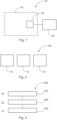
- Fig. 1 shows an example of a system 10 for monitoring a circuit breaker.
- the system comprises at least one sensor 20, and a processing unit 30.
- the at least one sensor is configured to be located and utilized to obtain at least one sensor data of a main shaft of an operational circuit breaker 40.
- the at least one sensor is configured to provide the at least one sensor data of the main shaft of the operational circuit breaker to the processing unit.
- the processing unit is configured to determine position and/or velocity information for a moveable contact of the operational circuit breaker. The determination comprises analysis of the at least one sensor data of the main shaft of the operational circuit breaker by a trained neural network implemented by the processing unit.
- the neural network was trained on the basis of at least one sensor data of a main shaft of a calibration circuit breaker 50 and at least one sensor data of a moveable contact and/or pushrod of the calibration circuit breaker.
- the at least one sensor data of the main shaft of the calibration circuit breaker was acquired at the same time as the at least one sensor data of the moveable contact and/or pushrod of the calibration circuit breaker.
- the calibration circuit breaker was the same type or model as the operational circuit breaker.
- At least one sensor 20, 60 utilized to obtain the at least one sensor data of the main shaft of the calibration circuit breaker was the same type or model as the at least one sensor 20 utilized to obtain the at least one sensor data of the main shaft of the operational circuit breaker.
- At least one sensor utilized to obtain the at least one sensor data of the main shaft of the calibration circuit breaker was located at the same or equivalent at least one location as the at least one sensor utilized to obtain the at least one sensor data of the main shaft of the operational circuit breaker.
- the at least one sensor utilized to obtain the at least one sensor data of the main shaft of the operational circuit breaker comprises one or more of: acceleration sensor; main shaft angle sensor.
- the at least one sensor 70 utilized to obtain the at least one sensor data of the moveable contact and/or pushrod of the calibration circuit breaker comprises one or more of: position sensor; velocity sensor.
- the position information and/or the velocity information for the moveable contact comprises a travel curve.
- the system comprises an output unit configured to output the position information and/or the velocity information for the moveable contact.
- the processing unit is configured to determine if the circuit breaker has a fault.
- the determination comprises analysis of the position information and/or the velocity information for the moveable contact.
- Fig. 2 shows an example of a system 100 for monitoring a two or three phase switchgear or control gear.
- the system comprises two or three systems 10 as described above with respect to Fig. 1 , where one of the systems 10 is used for a circuit breaker of each of the two or three phases.
- Fig. 3 shows a method 200 for monitoring a circuit breaker in its basic steps. The method comprises:
- the neural network was trained on the basis of at least one sensor data of a main shaft of a calibration circuit breaker and at least one sensor data of a moveable contact and/or pushrod of the calibration circuit breaker.
- the at least one sensor data of the main shaft of the calibration circuit breaker was acquired at the same time as the at least one sensor data of the moveable contact and/or pushrod of the calibration circuit breaker.
- the calibration circuit breaker was the same type or model as the operational circuit breaker.
- At least one sensor utilized to obtain the at least one sensor data of the main shaft of the calibration circuit breaker was the same type or model as the at least one sensor utilized to obtain the at least one sensor data of the main shaft of the operational circuit breaker.
- At least one sensor utilized to obtain the at least one sensor data of the main shaft of the calibration circuit breaker was located at the same or equivalent at least one location as the at least one sensor utilized to obtain the at least one sensor data of the main shaft of the operational circuit breaker.
- the at least one sensor utilized to obtain the at least one sensor data of the main shaft of the operational circuit breaker comprises one or more of: acceleration sensor; main shaft angle sensor.
- the at least one sensor utilized to obtain the at least one sensor data of the moveable contact and/or pushrod of the calibration circuit breaker comprises one or more of: position sensor; velocity sensor.
- the position information and/or the velocity information for the moveable contact comprises a travel curve.
- the system comprises an output unit and the method comprises outputting the position information and/or the velocity information for the moveable contact.
- Fig. 4 shows an example of a system 300 for training a neural network for monitoring a circuit breaker.
- the system comprises at least one first sensor 20, 60, at least one second sensor 70, and a processing unit 30, 80.
- the at least one first sensor is configured to be located and utilized to obtain at least one sensor data of a main shaft of a calibration circuit breaker 50.
- the at least one first sensor is configured to provide the at least one sensor data of the main shaft of the calibration circuit breaker to the processing unit.
- the at least one second sensor is configured to be located and utilized to obtain at least one sensor data of a moveable contact and/or pushrod of the calibration circuit breaker.
- the at least one second sensor is configured to provide the at least one sensor data of the moveable contact and/or pushrod of the calibration circuit breaker to the processing unit.
- the processing unit is configured to train a neural network.
- the training of the neural network comprises utilization of the at least one sensor data of the main shaft of the calibration circuit breaker and the at least one sensor data of the moveable contact and/or pushrod of the calibration circuit breaker.
- the trained neural network is configured to determine position and/or velocity information for a moveable contact of an operational circuit breaker 40 on the basis of analysis of at least one sensor data of a main shaft of the operational circuit breaker.
- the at least one sensor data of the main shaft of the calibration circuit breaker was acquired at the same time as the at least one sensor data of the moveable contact and/or pushrod of the calibration circuit breaker.
- the calibration circuit breaker is the same type or model as for the operational circuit breaker.
- the at least one first sensor (20, 60) utilized to obtain the at least one sensor data of the main shaft of the calibration circuit breaker is the same type or model as at least one sensor (20) that will be utilized to obtain the at least one sensor data of the main shaft of the operational circuit breaker.
- the at least one first sensor utilized to obtain the at least one sensor data of the main shaft of the calibration circuit breaker is located at the same or equivalent at least one location as the at least one sensor that will be utilized to obtain the at least one sensor data of the main shaft of the operational circuit breaker.
- the at least one first sensor utilized to obtain the at least one sensor data of the main shaft of the calibration circuit breaker comprises one or more of: acceleration sensor; main shaft angle sensor.
- the at least one second sensor (70) utilized to obtain the at least one sensor data of the moveable contact and/or pushrod of the calibration circuit breaker comprises one or more of: position sensor; velocity sensor.
- the position information and/or the velocity information for the moveable contact comprises a travel curve.
- Fig. 5 shows a method 400 for training a neural network for monitoring a circuit breaker in its basic steps. The method comprises:
- the method comprises acquiring at least one sensor data of the main shaft of the calibration circuit breaker at the same time as the at least one sensor data of the moveable contact and/or pushrod of the calibration circuit breaker.
- the calibration circuit breaker is the same type or model as for the operational circuit breaker.
- the at least one first sensor (20, 60) utilized to obtain the at least one sensor data of the main shaft of the calibration circuit breaker is the same type or model as at least one sensor (20) that will be utilized to obtain the at least one sensor data of the main shaft of the operational circuit breaker.
- the at least one first sensor utilized to obtain the at least one sensor data of the main shaft of the calibration circuit breaker is located at the same or equivalent at least one location as the at least one sensor that will be utilized to obtain the at least one sensor data of the main shaft of the operational circuit breaker.
- the at least one first sensor utilized to obtain the at least one sensor data of the main shaft of the calibration circuit breaker comprises one or more of: acceleration sensor; main shaft angle sensor.
- the at least one second sensor (70) utilized to obtain the at least one sensor data of the moveable contact and/or pushrod of the calibration circuit breaker comprises one or more of: position sensor; velocity sensor.
- the position information and/or the velocity information for the moveable contact comprises a travel curve.
- the system for monitoring a circuit breaker system for monitoring a two or three phase switchgear or controlgear, method for monitoring a circuit breaker, system for training a neural network for monitoring a circuit breaker, and method for training a neural network for monitoring a circuit breaker and now described in specific detail, where reference is made to Fig. 6 .
- condition monitoring and diagnosis of the operating mechanism of a circuit breaker is mainly based on travel curve measurements.
- the reason is that most of the failure modes can be captured by position or velocity sensors measuring the travel curve.
- acquiring such data is hard to achieve as it requires robust, reliable sensors fulfilling the requirements in installation space and lifetime of the CB.
- the inventors realised that other types of sensors such as accelerometers that are more appropriate and can be easier to mount in the CB can be utilized in a completely different way and new way in order to derive this travel curve information.
- the inventors have applied methods of artificial intelligence (AI) for extracting the position of the moving contact for each pole from this other sensor data (for example the accelerometers), and thus enabling CB drive monitoring based on travel curves.
- AI artificial intelligence
- the generated travel curves can be also used to monitor electrical failure modes as for instance contact ablation.
- the solution involves using a sequence-to-sequence artificial intelligence (AI) model that first learns to generate the travel curve data from the other sensor data by training it with examples that contain both travel curve and further sensor measurements, e.g. accelerometers, rotary encoders for measuring the main shaft angle, etc.
- AI sequence-to-sequence artificial intelligence
- the model is able to extract travel curve information also on data that was not used for the training of the model, and when the travel curve information is not available.
- the accuracy of this method is evaluated in two ways:
- the solution utilizes a dataset with both travel curve signals and further sensor data, which were recorded simultaneously from the same device. Then use an artificial intelligence (AI) model is used to learn to generate the travel curves from the further sensor data (that was acquired at the same time as the travel curve signals) which could be accelerometer signals, angle measurements of the main shaft, etc.
- AI artificial intelligence
- travel curve data can be generated only for the "further sensor data" such as from accelerometers that can be more convenient placed and used, for a new circuit breaker of the same type or model as that used for generating the neural network model.
- the model can be used to diagnose the health of circuit breaker drives using only the measurement data from other sensors.
- Fig. 6 provides an overview work flow of the above described technique.
Landscapes
- Engineering & Computer Science (AREA)
- Physics & Mathematics (AREA)
- General Physics & Mathematics (AREA)
- Theoretical Computer Science (AREA)
- Automation & Control Theory (AREA)
- Data Mining & Analysis (AREA)
- Computing Systems (AREA)
- Biomedical Technology (AREA)
- Biophysics (AREA)
- Computational Linguistics (AREA)
- Life Sciences & Earth Sciences (AREA)
- Evolutionary Computation (AREA)
- General Health & Medical Sciences (AREA)
- Molecular Biology (AREA)
- Artificial Intelligence (AREA)
- General Engineering & Computer Science (AREA)
- Mathematical Physics (AREA)
- Software Systems (AREA)
- Health & Medical Sciences (AREA)
- Manufacturing & Machinery (AREA)
- Arc-Extinguishing Devices That Are Switches (AREA)
- Keying Circuit Devices (AREA)
Claims (11)
- Système (10) de surveillance d'un disjoncteur, le système comprenant :- au moins un capteur (20) ; et- une unité de traitement (30) ;dans lequel l'au moins un capteur est configuré pour être situé et utilisé afin d'obtenir au moins une donnée de capteur d'un arbre principal d'un disjoncteur opérationnel (40), où l'au moins un capteur utilisé pour obtenir l'au moins une donnée de capteur de l'arbre principal du disjoncteur opérationnel comprend un ou plusieurs des éléments suivants : un capteur d'accélération ; un capteur d'angle d'arbre principal ;dans lequel l'au moins un capteur est configuré pour fournir l'au moins une donnée de capteur de l'arbre principal du disjoncteur opérationnel à l'unité de traitement ; etdans lequel l'unité de traitement est configurée pour déterminer les informations de position et/ou de vitesse d'un contact mobile du disjoncteur opérationnel, caractérisé en ce que la détermination comprend l'analyse de l'au moins une donnée de capteur de l'arbre principal du disjoncteur opérationnel par un réseau neuronal entraîné mis en œuvre par l'unité de traitement ;dans lequel le réseau neuronal a été entraîné sur la base d'au moins une donnée de capteur d'un arbre principal d'un disjoncteur d'étalonnage (50) et d'au moins une donnée de capteur d'un contact mobile et/ou d'une tige de poussée du disjoncteur d'étalonnage, où au moins un capteur (20, 60) utilisé pour obtenir l'au moins une donnée de capteur de l'arbre principal du disjoncteur d'étalonnage comprend un ou plusieurs des éléments suivants : un capteur d'accélération ; un capteur d'angle d'arbre principal, où au moins un capteur (70) utilisé pour obtenir ladite au moins une données de capteur du contact mobile et/ou de la tige de poussée du disjoncteur d'étalonnage comprend un ou plusieurs des éléments suivants : un capteur de position ; un capteur de vitesse.
- Système selon la revendication 1, dans lequel l'au moins une donnée de capteur de l'arbre principal du disjoncteur d'étalonnage a été acquise en même temps que l'au moins une donnée de capteur du contact mobile et/ou de la tige de poussée du disjoncteur d'étalonnage.
- Système selon l'une quelconque des revendications 1 et 2, dans lequel le disjoncteur d'étalonnage est du même type ou modèle que le disjoncteur opérationnel.
- Système selon l'une quelconque des revendications 1 à 3, dans lequel au moins un capteur utilisé pour obtenir l'au moins une donnée de capteur de l'arbre principal du disjoncteur d'étalonnage était situé au même endroit ou à un endroit au moins équivalent à celui de l'au moins un capteur utilisé pour obtenir l'au moins une donnée de capteur de l'arbre principal du disjoncteur opérationnel.
- Système selon l'une quelconque des revendications 1 à 4, dans lequel les informations de position et/ou les informations de vitesse pour le contact mobile comprennent une courbe de déplacement.
- Système selon l'une quelconque des revendications 1 à 5, dans lequel le système comprend une unité de sortie configurée pour délivrer en sortie les informations de position et/ou les informations de vitesse pour le contact mobile.
- Système selon l'une quelconque des revendications 1 à 6, dans lequel l'unité de traitement est configurée pour déterminer si le disjoncteur présente un défaut, la détermination comprenant l'analyse des informations de position et/ou des informations de vitesse pour le contact mobile.
- Système (100) de surveillance d'un appareillage de commutation ou de commande à deux ou trois phases, le système comprenant deux ou trois systèmes (10) selon l'une quelconque des revendications 1 à 7, un pour un disjoncteur de chacune des deux ou trois phases.
- Procédé (200) de surveillance d'un disjoncteur, le procédé comprenant les étapes suivantes :a) utiliser (210) au moins un capteur situé de manière à obtenir au moins une donnée de capteur d'un arbre principal d'un disjoncteur opérationnel, où l'au moins un capteur utilisé pour obtenir l'au moins une donnée de capteur de l'arbre principal du disjoncteur opérationnel comprend un ou plusieurs des éléments suivants : un capteur d'accélération ; un capteur d'angle d'arbre principal ;b) fournir (220) l'au moins une donnée de capteur de l'arbre principal du disjoncteur opérationnel à une unité de traitement ; etc) déterminer (230) par l'unité de traitement des informations de position et/ou de vitesse pour un contact mobile du disjoncteur opérationnel, ce qui est caractérisé en ce que la détermination comprend l'analyse de l'au moins une donnée de capteur de l'arbre principal du disjoncteur opérationnel par un réseau neuronal entraîné mis en œuvre par l'unité de traitement, où le réseau neuronal a été entraîné sur la base d'au moins une donnée de capteur d'un arbre principal d'un disjoncteur d'étalonnage et d'au moins une donnée de capteur d'un contact mobile et/ou d'une tige de poussée du disjoncteur d'étalonnage, où au moins un capteur utilisé pour obtenir l'au moins une donnée de capteur de l'arbre principal du disjoncteur d'étalonnage comprend un ou plusieurs des éléments suivants : un capteur d'accélération ; un capteur d'angle d'arbre principal, où au moins un capteur utilisé pour obtenir l'au moins une donnée de capteur du contact mobile et/ou de la tige de poussée du disjoncteur d'étalonnage comprend un ou plusieurs des éléments suivants : un capteur de position ; un capteur de vitesse.
- Système (300) d'entraînement d'un réseau neuronal pour la surveillance d'un disjoncteur, le système comprenant :- au moins un premier capteur (20, 60) ;- au moins un deuxième capteur (70) ; et- une unité de traitement (30, 80) ;dans lequel l'au moins un premier capteur est configuré pour être situé et utilisé afin d'obtenir au moins une donnée de capteur d'un arbre principal d'un disjoncteur d'étalonnage (50), où l'au moins un premier capteur utilisé pour obtenir l'au moins une donnée de capteur de l'arbre principal du disjoncteur d'étalonnage comprend un ou plusieurs des éléments suivants : un capteur d'accélération ; un capteur d'angle d'arbre principal ;dans lequel l'au moins un premier capteur est configuré pour fournir à l'unité de traitement l'au moins une donnée de capteur de l'arbre principal du disjoncteur d'étalonnage ;dans lequel l'au moins un deuxième capteur est configuré pour être situé et utilisé afin d'obtenir au moins une donnée de capteur d'un contact mobile et/ou d'une tige de poussée du disjoncteur d'étalonnage, où l'au moins un deuxième capteur utilisé pour obtenir l'au moins une donnée de capteur du contact mobile et/ou de la tige de poussée du disjoncteur d'étalonnage comprend un ou plusieurs des éléments suivants : un capteur de position ; un capteur de vitesse ;dans lequel l'au moins un deuxième capteur est configuré pour fournir à l'unité de traitement l'au moins une donnée de capteur du contact mobile et/ou de la tige de poussée du disjoncteur d'étalonnage ; etle système étant caractérisé en ce que l'unité de traitement est configurée pour entraîner un réseau neuronal, où l'entraînement du réseau neuronal comprend l'utilisation d'au moins une donnée de capteur de l'arbre principal du disjoncteur d'étalonnage et d'au moins une donnée de capteur du contact mobile et/ou de la tige de poussée du disjoncteur d'étalonnage, et où le réseau neuronal entraîné est configuré pour déterminer des informations de position et/ou de vitesse pour un contact mobile d'un disjoncteur opérationnel (40) sur la base de l'analyse d'au moins une donnée de capteur d'un arbre principal du disjoncteur opérationnel, et où l'au moins un premier capteur utilisé pour obtenir l'au moins une donnée de capteur de l'arbre principal du disjoncteur opérationnel comprend un ou plusieurs des éléments suivants : un capteur d'accélération ; un capteur d'angle d'arbre principal.
- Procédé (400) d'entraînement d'un réseau neuronal pour la surveillance d'un disjoncteur, le procédé comprenant les étapes suivantes :a1) utiliser (410) au moins un premier capteur situé de manière à obtenir au moins une donnée de capteur d'un arbre principal d'un disjoncteur d'étalonnage, où l'au moins un premier capteur utilisé pour obtenir l'au moins une donnée de capteur de l'arbre principal du disjoncteur d'étalonnage comprend un ou plusieurs des éléments suivants : un capteur d'accélération ; un capteur d'angle d'arbre principal ;b1) fournir (420) l'au moins une donnée de capteur de l'arbre principal du disjoncteur d'étalonnage à une unité de traitement ;c1) utiliser (430) au moins un deuxième capteur situé de manière à obtenir au moins une donnée de capteur d'un contact mobile et/ou d'une tige de poussée du disjoncteur d'étalonnage, où l'au moins un deuxième capteur utilisé pour obtenir l'au moins une donnée de capteur du contact mobile et/ou de la tige de poussée du disjoncteur d'étalonnage comprend un ou plusieurs des éléments suivants : un capteur de position ; un capteur de vitesse ;d1) fournir (440) l'au moins une donnée de capteur du contact mobile et/ou d'une tige de poussée du disjoncteur d'étalonnage à l'unité de traitement ; ete1) caractérisé en ce que le procédé comprend : l'entraînement (450) d'un réseau neuronal par l'unité de traitement, où l'entraînement du réseau neuronal comprend l'utilisation de l'au moins une donnée de capteur de l'arbre principal du disjoncteur d'étalonnage et de l'au moins une donnée de capteur du contact mobile et/ou de la tige de poussée du disjoncteur d'étalonnage, et où le réseau neuronal entraîné est configuré pour déterminer des informations de position et/ou de vitesse pour un contact mobile d'un disjoncteur opérationnel sur la base de l'analyse d'au moins une donnée de capteur d'un arbre principal du disjoncteur opérationnel, et où l'au moins un premier capteur utilisé pour obtenir l'au moins une donnée de capteur de l'arbre principal du disjoncteur opérationnel comprend un ou plusieurs des éléments suivants : un capteur d'accélération ; un capteur d'angle d'arbre principal.
Priority Applications (3)
| Application Number | Priority Date | Filing Date | Title |
|---|---|---|---|
| EP20209540.2A EP4002022B1 (fr) | 2020-11-24 | 2020-11-24 | Système de surveillance d'un disjoncteur |
| CN202111393011.7A CN114545217B (zh) | 2020-11-24 | 2021-11-23 | 用于监测断路器的系统 |
| US17/534,468 US11699561B2 (en) | 2020-11-24 | 2021-11-24 | System for monitoring a circuit breaker |
Applications Claiming Priority (1)
| Application Number | Priority Date | Filing Date | Title |
|---|---|---|---|
| EP20209540.2A EP4002022B1 (fr) | 2020-11-24 | 2020-11-24 | Système de surveillance d'un disjoncteur |
Publications (2)
| Publication Number | Publication Date |
|---|---|
| EP4002022A1 EP4002022A1 (fr) | 2022-05-25 |
| EP4002022B1 true EP4002022B1 (fr) | 2025-04-09 |
Family
ID=73597794
Family Applications (1)
| Application Number | Title | Priority Date | Filing Date |
|---|---|---|---|
| EP20209540.2A Active EP4002022B1 (fr) | 2020-11-24 | 2020-11-24 | Système de surveillance d'un disjoncteur |
Country Status (3)
| Country | Link |
|---|---|
| US (1) | US11699561B2 (fr) |
| EP (1) | EP4002022B1 (fr) |
| CN (1) | CN114545217B (fr) |
Families Citing this family (7)
| Publication number | Priority date | Publication date | Assignee | Title |
|---|---|---|---|---|
| EP4002021B1 (fr) * | 2020-11-17 | 2025-03-19 | ABB Schweiz AG | Système de surveillance d'un disjoncteur |
| EP4125106A1 (fr) * | 2021-07-27 | 2023-02-01 | Abb Schweiz Ag | Système de surveillance pour disjoncteur basse tension, moyenne tension ou haute tension |
| EP4124874A1 (fr) * | 2021-07-30 | 2023-02-01 | Abb Schweiz Ag | Système de surveillance pour un disjoncteur basse tension, moyenne tension ou haute tension |
| EP4124873A1 (fr) * | 2021-07-30 | 2023-02-01 | Abb Schweiz Ag | Système de surveillance de disjoncteur basse tension, moyenne tension ou haute tension |
| WO2024020739A1 (fr) * | 2022-07-25 | 2024-02-01 | 西门子股份公司 | Procédé de génération de données d'apprentissage, procédé d'entraînement de modèle, dispositif électronique et support |
| CN116243155A (zh) * | 2023-02-09 | 2023-06-09 | 国网河北省电力有限公司电力科学研究院 | 断路器故障诊断方法、装置、设备以及存储介质 |
| EP4586292A1 (fr) * | 2024-01-09 | 2025-07-16 | Abb Schweiz Ag | Utilisation de données de vibration de disjoncteur |
Family Cites Families (20)
| Publication number | Priority date | Publication date | Assignee | Title |
|---|---|---|---|---|
| US6522247B2 (en) * | 2000-05-23 | 2003-02-18 | Kabushiki Kaisha Toshiba | Apparatus monitoring system and apparatus monitoring method |
| US6963203B2 (en) * | 2003-03-31 | 2005-11-08 | General Electric Company | Methods and apparatus for analyzing high voltage circuit breakers |
| US20090113049A1 (en) * | 2006-04-12 | 2009-04-30 | Edsa Micro Corporation | Systems and methods for real-time forecasting and predicting of electrical peaks and managing the energy, health, reliability, and performance of electrical power systems based on an artificial adaptive neural network |
| US8718968B2 (en) | 2010-08-31 | 2014-05-06 | Abb Technology Ag | Circuit breaker interrupter travel curve estimation |
| CN102288879B (zh) | 2011-04-25 | 2013-04-03 | 天津大学 | 基于无线网络的开关柜局部放电超声检测装置 |
| CN104166773A (zh) * | 2014-08-26 | 2014-11-26 | 新疆特变电工自控设备有限公司 | 一种测量断路器触头行程与主轴旋转角度关系的方法 |
| CN104849653B (zh) * | 2015-04-09 | 2018-07-20 | 广州供电局有限公司 | 断路器的机械特性测量方法和系统 |
| US10012697B2 (en) * | 2015-08-13 | 2018-07-03 | Eaton Intelligent Power Limited | Failure prediction device and method for vacuum circuit breakers |
| CN105911464A (zh) * | 2016-04-19 | 2016-08-31 | 北京双杰智远电力技术有限公司 | 基于加速度传感器的断路器在线监测方法、装置及系统 |
| EP3270398B1 (fr) * | 2016-07-12 | 2021-04-07 | ABB Schweiz AG | Actionneur pour un disjoncteur moyenne tension |
| CN107490760A (zh) * | 2017-08-22 | 2017-12-19 | 西安工程大学 | 基于遗传算法改进模糊神经网络的断路器故障诊断方法 |
| CN111183500B (zh) * | 2017-10-16 | 2022-09-02 | 日立能源瑞士股份公司 | 用于监测断路器的方法和装置以及使用该装置的物联网 |
| CN112689932B (zh) * | 2018-09-20 | 2024-07-09 | 西门子歌美飒可再生能源公司 | 在网络接地故障期间控制可再生发电设备的方法 |
| DE102019202650A1 (de) * | 2019-02-27 | 2020-08-27 | Siemens Aktiengesellschaft | Bewertung eines Leistungsschalters |
| US20220202088A1 (en) * | 2019-05-03 | 2022-06-30 | Jt International S.A. | Aerosol Generation Device Having A Thermal Bridge |
| CN110716133B (zh) * | 2019-09-06 | 2022-03-15 | 国网浙江省电力有限公司嘉兴供电公司 | 一种基于物联网及大数据技术的高压断路器故障研判方法 |
| CN110780191B (zh) * | 2019-09-27 | 2022-04-29 | 国网浙江省电力有限公司杭州供电公司 | 基于多传感器的断路器机械特性在线监测方法及装置 |
| CN110929763B (zh) * | 2019-10-30 | 2022-06-21 | 西安交通大学 | 基于多源数据融合的中压真空断路器机械故障诊断方法 |
| CN110907811A (zh) * | 2019-11-18 | 2020-03-24 | 广东欧文特电气有限公司 | 一种中压开关柜触头行程测量方法 |
| EP4002021B1 (fr) * | 2020-11-17 | 2025-03-19 | ABB Schweiz AG | Système de surveillance d'un disjoncteur |
-
2020
- 2020-11-24 EP EP20209540.2A patent/EP4002022B1/fr active Active
-
2021
- 2021-11-23 CN CN202111393011.7A patent/CN114545217B/zh active Active
- 2021-11-24 US US17/534,468 patent/US11699561B2/en active Active
Also Published As
| Publication number | Publication date |
|---|---|
| US20220165526A1 (en) | 2022-05-26 |
| EP4002022A1 (fr) | 2022-05-25 |
| US11699561B2 (en) | 2023-07-11 |
| CN114545217A (zh) | 2022-05-27 |
| CN114545217B (zh) | 2026-01-02 |
Similar Documents
| Publication | Publication Date | Title |
|---|---|---|
| EP4002022B1 (fr) | Système de surveillance d'un disjoncteur | |
| EP4002021B1 (fr) | Système de surveillance d'un disjoncteur | |
| US9803996B2 (en) | System for ascertaining the number of revolutions of a rotationally mounted shaft, and method for ascertaining the number of revolutions of a rotationally mounted shaft | |
| EP4124873A1 (fr) | Système de surveillance de disjoncteur basse tension, moyenne tension ou haute tension | |
| EP4124874A1 (fr) | Système de surveillance pour un disjoncteur basse tension, moyenne tension ou haute tension | |
| CN112528227A (zh) | 一种基于数理统计的传感器异常数据识别方法 | |
| CN108844644B (zh) | 一种电池温度采样系统及汽车 | |
| US8271227B2 (en) | Measuring transducer | |
| JPS6211154Y2 (fr) | ||
| CN113708225A (zh) | 一种开关柜内温湿度监测装置及监测方法 | |
| CN110553830B (zh) | 一种金属封闭开关设备机械特性在线检测方法 | |
| CN108731792B (zh) | 一种判断列车过车的方法及振动检测装置 | |
| KR101490471B1 (ko) | 신호 계측 및 진단 시스템과 그 방법 | |
| CN114674458A (zh) | 一种磁悬浮列车的温度检测方法、装置、系统及服务器 | |
| CN112729099A (zh) | 间隙探头的检测方法、装置、电子设备及计算机存储介质 | |
| CN112611983B (zh) | 轨道交通数字量输入输出通道检测方法及装置 | |
| CN215579597U (zh) | 一种开关柜内温湿度监测装置 | |
| CN118226153A (zh) | 一种应用于充电桩的录波处理装置、系统及方法 | |
| JP2014126885A (ja) | 車両情報記憶装置および車両情報記憶方法 | |
| US20250096713A1 (en) | Method for Operating an Electric Drive System | |
| JP7759198B2 (ja) | 遮断器音響診断装置及び方法 | |
| KR20260059782A (ko) | 궤도회로 상태 진단 시스템 및 이를 이용한 궤도회로 상태 진단방법 | |
| CN110635964A (zh) | 用于在总线通信时进行错误处理的方法以及总线通信系统 | |
| EP4586292A1 (fr) | Utilisation de données de vibration de disjoncteur | |
| CN121317487A (zh) | 电梯轿厢门的故障判定方法及其系统 |
Legal Events
| Date | Code | Title | Description |
|---|---|---|---|
| PUAI | Public reference made under article 153(3) epc to a published international application that has entered the european phase |
Free format text: ORIGINAL CODE: 0009012 |
|
| STAA | Information on the status of an ep patent application or granted ep patent |
Free format text: STATUS: THE APPLICATION HAS BEEN PUBLISHED |
|
| AK | Designated contracting states |
Kind code of ref document: A1 Designated state(s): AL AT BE BG CH CY CZ DE DK EE ES FI FR GB GR HR HU IE IS IT LI LT LU LV MC MK MT NL NO PL PT RO RS SE SI SK SM TR |
|
| STAA | Information on the status of an ep patent application or granted ep patent |
Free format text: STATUS: REQUEST FOR EXAMINATION WAS MADE |
|
| 17P | Request for examination filed |
Effective date: 20221121 |
|
| RBV | Designated contracting states (corrected) |
Designated state(s): AL AT BE BG CH CY CZ DE DK EE ES FI FR GB GR HR HU IE IS IT LI LT LU LV MC MK MT NL NO PL PT RO RS SE SI SK SM TR |
|
| GRAP | Despatch of communication of intention to grant a patent |
Free format text: ORIGINAL CODE: EPIDOSNIGR1 |
|
| STAA | Information on the status of an ep patent application or granted ep patent |
Free format text: STATUS: GRANT OF PATENT IS INTENDED |
|
| RIC1 | Information provided on ipc code assigned before grant |
Ipc: H01H 11/00 20060101ALI20241113BHEP Ipc: G05B 15/02 20060101ALI20241113BHEP Ipc: G05B 13/02 20060101AFI20241113BHEP |
|
| INTG | Intention to grant announced |
Effective date: 20241210 |
|
| GRAS | Grant fee paid |
Free format text: ORIGINAL CODE: EPIDOSNIGR3 |
|
| GRAA | (expected) grant |
Free format text: ORIGINAL CODE: 0009210 |
|
| STAA | Information on the status of an ep patent application or granted ep patent |
Free format text: STATUS: THE PATENT HAS BEEN GRANTED |
|
| AK | Designated contracting states |
Kind code of ref document: B1 Designated state(s): AL AT BE BG CH CY CZ DE DK EE ES FI FR GB GR HR HU IE IS IT LI LT LU LV MC MK MT NL NO PL PT RO RS SE SI SK SM TR |
|
| REG | Reference to a national code |
Ref country code: GB Ref legal event code: FG4D |
|
| REG | Reference to a national code |
Ref country code: CH Ref legal event code: EP |
|
| REG | Reference to a national code |
Ref country code: DE Ref legal event code: R096 Ref document number: 602020049020 Country of ref document: DE |
|
| REG | Reference to a national code |
Ref country code: IE Ref legal event code: FG4D |
|
| REG | Reference to a national code |
Ref country code: NL Ref legal event code: MP Effective date: 20250409 |
|
| PG25 | Lapsed in a contracting state [announced via postgrant information from national office to epo] |
Ref country code: NL Free format text: LAPSE BECAUSE OF FAILURE TO SUBMIT A TRANSLATION OF THE DESCRIPTION OR TO PAY THE FEE WITHIN THE PRESCRIBED TIME-LIMIT Effective date: 20250409 |
|
| REG | Reference to a national code |
Ref country code: AT Ref legal event code: MK05 Ref document number: 1784073 Country of ref document: AT Kind code of ref document: T Effective date: 20250409 |
|
| PG25 | Lapsed in a contracting state [announced via postgrant information from national office to epo] |
Ref country code: FI Free format text: LAPSE BECAUSE OF FAILURE TO SUBMIT A TRANSLATION OF THE DESCRIPTION OR TO PAY THE FEE WITHIN THE PRESCRIBED TIME-LIMIT Effective date: 20250409 Ref country code: ES Free format text: LAPSE BECAUSE OF FAILURE TO SUBMIT A TRANSLATION OF THE DESCRIPTION OR TO PAY THE FEE WITHIN THE PRESCRIBED TIME-LIMIT Effective date: 20250409 Ref country code: PT Free format text: LAPSE BECAUSE OF FAILURE TO SUBMIT A TRANSLATION OF THE DESCRIPTION OR TO PAY THE FEE WITHIN THE PRESCRIBED TIME-LIMIT Effective date: 20250811 |
|
| REG | Reference to a national code |
Ref country code: LT Ref legal event code: MG9D |
|
| PG25 | Lapsed in a contracting state [announced via postgrant information from national office to epo] |
Ref country code: GR Free format text: LAPSE BECAUSE OF FAILURE TO SUBMIT A TRANSLATION OF THE DESCRIPTION OR TO PAY THE FEE WITHIN THE PRESCRIBED TIME-LIMIT Effective date: 20250710 Ref country code: NO Free format text: LAPSE BECAUSE OF FAILURE TO SUBMIT A TRANSLATION OF THE DESCRIPTION OR TO PAY THE FEE WITHIN THE PRESCRIBED TIME-LIMIT Effective date: 20250709 |
|
| PG25 | Lapsed in a contracting state [announced via postgrant information from national office to epo] |
Ref country code: PL Free format text: LAPSE BECAUSE OF FAILURE TO SUBMIT A TRANSLATION OF THE DESCRIPTION OR TO PAY THE FEE WITHIN THE PRESCRIBED TIME-LIMIT Effective date: 20250409 |
|
| PG25 | Lapsed in a contracting state [announced via postgrant information from national office to epo] |
Ref country code: BG Free format text: LAPSE BECAUSE OF FAILURE TO SUBMIT A TRANSLATION OF THE DESCRIPTION OR TO PAY THE FEE WITHIN THE PRESCRIBED TIME-LIMIT Effective date: 20250409 |
|
| PG25 | Lapsed in a contracting state [announced via postgrant information from national office to epo] |
Ref country code: HR Free format text: LAPSE BECAUSE OF FAILURE TO SUBMIT A TRANSLATION OF THE DESCRIPTION OR TO PAY THE FEE WITHIN THE PRESCRIBED TIME-LIMIT Effective date: 20250409 |
|
| PG25 | Lapsed in a contracting state [announced via postgrant information from national office to epo] |
Ref country code: AT Free format text: LAPSE BECAUSE OF FAILURE TO SUBMIT A TRANSLATION OF THE DESCRIPTION OR TO PAY THE FEE WITHIN THE PRESCRIBED TIME-LIMIT Effective date: 20250409 |
|
| PG25 | Lapsed in a contracting state [announced via postgrant information from national office to epo] |
Ref country code: RS Free format text: LAPSE BECAUSE OF FAILURE TO SUBMIT A TRANSLATION OF THE DESCRIPTION OR TO PAY THE FEE WITHIN THE PRESCRIBED TIME-LIMIT Effective date: 20250709 |
|
| PG25 | Lapsed in a contracting state [announced via postgrant information from national office to epo] |
Ref country code: IS Free format text: LAPSE BECAUSE OF FAILURE TO SUBMIT A TRANSLATION OF THE DESCRIPTION OR TO PAY THE FEE WITHIN THE PRESCRIBED TIME-LIMIT Effective date: 20250809 |
|
| PG25 | Lapsed in a contracting state [announced via postgrant information from national office to epo] |
Ref country code: LV Free format text: LAPSE BECAUSE OF FAILURE TO SUBMIT A TRANSLATION OF THE DESCRIPTION OR TO PAY THE FEE WITHIN THE PRESCRIBED TIME-LIMIT Effective date: 20250409 |
|
| PGFP | Annual fee paid to national office [announced via postgrant information from national office to epo] |
Ref country code: DE Payment date: 20251119 Year of fee payment: 6 |
|
| REG | Reference to a national code |
Ref country code: DE Ref legal event code: R097 Ref document number: 602020049020 Country of ref document: DE |
|
| PG25 | Lapsed in a contracting state [announced via postgrant information from national office to epo] |
Ref country code: DK Free format text: LAPSE BECAUSE OF FAILURE TO SUBMIT A TRANSLATION OF THE DESCRIPTION OR TO PAY THE FEE WITHIN THE PRESCRIBED TIME-LIMIT Effective date: 20250409 Ref country code: SM Free format text: LAPSE BECAUSE OF FAILURE TO SUBMIT A TRANSLATION OF THE DESCRIPTION OR TO PAY THE FEE WITHIN THE PRESCRIBED TIME-LIMIT Effective date: 20250409 |
|
| PGFP | Annual fee paid to national office [announced via postgrant information from national office to epo] |
Ref country code: IT Payment date: 20251125 Year of fee payment: 6 |
|
| PGFP | Annual fee paid to national office [announced via postgrant information from national office to epo] |
Ref country code: FR Payment date: 20251126 Year of fee payment: 6 |
|
| PG25 | Lapsed in a contracting state [announced via postgrant information from national office to epo] |
Ref country code: CZ Free format text: LAPSE BECAUSE OF FAILURE TO SUBMIT A TRANSLATION OF THE DESCRIPTION OR TO PAY THE FEE WITHIN THE PRESCRIBED TIME-LIMIT Effective date: 20250409 |
|
| PG25 | Lapsed in a contracting state [announced via postgrant information from national office to epo] |
Ref country code: EE Free format text: LAPSE BECAUSE OF FAILURE TO SUBMIT A TRANSLATION OF THE DESCRIPTION OR TO PAY THE FEE WITHIN THE PRESCRIBED TIME-LIMIT Effective date: 20250409 |
|
| PG25 | Lapsed in a contracting state [announced via postgrant information from national office to epo] |
Ref country code: RO Free format text: LAPSE BECAUSE OF FAILURE TO SUBMIT A TRANSLATION OF THE DESCRIPTION OR TO PAY THE FEE WITHIN THE PRESCRIBED TIME-LIMIT Effective date: 20250409 Ref country code: SK Free format text: LAPSE BECAUSE OF FAILURE TO SUBMIT A TRANSLATION OF THE DESCRIPTION OR TO PAY THE FEE WITHIN THE PRESCRIBED TIME-LIMIT Effective date: 20250409 |
|
| PLBE | No opposition filed within time limit |
Free format text: ORIGINAL CODE: 0009261 |
|
| STAA | Information on the status of an ep patent application or granted ep patent |
Free format text: STATUS: NO OPPOSITION FILED WITHIN TIME LIMIT |
|
| REG | Reference to a national code |
Ref country code: CH Ref legal event code: L10 Free format text: ST27 STATUS EVENT CODE: U-0-0-L10-L00 (AS PROVIDED BY THE NATIONAL OFFICE) Effective date: 20260218 |
|
| 26N | No opposition filed |
Effective date: 20260112 |