EP4002039B1 - Procédé de détermination de l'étendue de dommages - Google Patents
Procédé de détermination de l'étendue de dommages Download PDFInfo
- Publication number
- EP4002039B1 EP4002039B1 EP21193150.6A EP21193150A EP4002039B1 EP 4002039 B1 EP4002039 B1 EP 4002039B1 EP 21193150 A EP21193150 A EP 21193150A EP 4002039 B1 EP4002039 B1 EP 4002039B1
- Authority
- EP
- European Patent Office
- Prior art keywords
- damage
- actuation
- component
- actuation parameter
- function
- Prior art date
- Legal status (The legal status is an assumption and is not a legal conclusion. Google has not performed a legal analysis and makes no representation as to the accuracy of the status listed.)
- Active
Links
Images

Classifications
-
- G—PHYSICS
- G05—CONTROLLING; REGULATING
- G05B—CONTROL OR REGULATING SYSTEMS IN GENERAL; FUNCTIONAL ELEMENTS OF SUCH SYSTEMS; MONITORING OR TESTING ARRANGEMENTS FOR SUCH SYSTEMS OR ELEMENTS
- G05B23/00—Testing or monitoring of control systems or parts thereof
- G05B23/02—Electric testing or monitoring
- G05B23/0205—Electric testing or monitoring by means of a monitoring system capable of detecting and responding to faults
- G05B23/0259—Electric testing or monitoring by means of a monitoring system capable of detecting and responding to faults characterized by the response to fault detection
- G05B23/0283—Predictive maintenance, e.g. involving the monitoring of a system and, based on the monitoring results, taking decisions on the maintenance schedule of the monitored system; Estimating remaining useful life [RUL]
-
- G—PHYSICS
- G01—MEASURING; TESTING
- G01M—TESTING STATIC OR DYNAMIC BALANCE OF MACHINES OR STRUCTURES; TESTING OF STRUCTURES OR APPARATUS, NOT OTHERWISE PROVIDED FOR
- G01M13/00—Testing of machine parts
-
- G—PHYSICS
- G01—MEASURING; TESTING
- G01M—TESTING STATIC OR DYNAMIC BALANCE OF MACHINES OR STRUCTURES; TESTING OF STRUCTURES OR APPARATUS, NOT OTHERWISE PROVIDED FOR
- G01M15/00—Testing of engines
-
- G—PHYSICS
- G01—MEASURING; TESTING
- G01M—TESTING STATIC OR DYNAMIC BALANCE OF MACHINES OR STRUCTURES; TESTING OF STRUCTURES OR APPARATUS, NOT OTHERWISE PROVIDED FOR
- G01M99/00—Subject matter not provided for in other groups of this subclass
-
- G—PHYSICS
- G01—MEASURING; TESTING
- G01R—MEASURING ELECTRIC VARIABLES; MEASURING MAGNETIC VARIABLES
- G01R31/00—Arrangements for testing electric properties; Arrangements for locating electric faults; Arrangements for electrical testing characterised by what is being tested not provided for elsewhere
-
- G—PHYSICS
- G05—CONTROLLING; REGULATING
- G05B—CONTROL OR REGULATING SYSTEMS IN GENERAL; FUNCTIONAL ELEMENTS OF SUCH SYSTEMS; MONITORING OR TESTING ARRANGEMENTS FOR SUCH SYSTEMS OR ELEMENTS
- G05B23/00—Testing or monitoring of control systems or parts thereof
- G05B23/02—Electric testing or monitoring
- G05B23/0205—Electric testing or monitoring by means of a monitoring system capable of detecting and responding to faults
- G05B23/0259—Electric testing or monitoring by means of a monitoring system capable of detecting and responding to faults characterized by the response to fault detection
- G05B23/0286—Modifications to the monitored process, e.g. stopping operation or adapting control
-
- G—PHYSICS
- G07—CHECKING-DEVICES
- G07C—TIME OR ATTENDANCE REGISTERS; REGISTERING OR INDICATING THE WORKING OF MACHINES; GENERATING RANDOM NUMBERS; VOTING OR LOTTERY APPARATUS; ARRANGEMENTS, SYSTEMS OR APPARATUS FOR CHECKING NOT PROVIDED FOR ELSEWHERE
- G07C5/00—Registering or indicating the working of vehicles
- G07C5/08—Registering or indicating performance data other than driving, working, idle, or waiting time, with or without registering driving, working, idle or waiting time
Definitions
- the invention relates to a method for determining the extent of damage to a component of a mechatronic system.
- the function of a rolling bearing can be determined through vibration measurements, and maintenance can be triggered if the vibrations exceed a predefined threshold.
- wear on a valve seat of an internal combustion engine caused by a leak, leads to increased fuel consumption and deviations in exhaust gas composition. Accordingly, corresponding measured values can serve as an indication of increasing wear on the valve seat and trigger maintenance.
- US 2011/137575 A1 discloses real-time predictive analysis and usage-based remaining life assessment of turbine engine components and their display
- US 2012/283963 A1 discloses a method for predicting the remaining service life of an engine and its components. However, they do not disclose that an actuation parameter of a compensation device, which forms the basis for subsequent actuation, is used to determine the extent of damage.
- the object of the invention is to provide a method for determining the extent of damage to a component of a mechatronic system, which, in mechatronic systems with a compensation device, can compensate for the effects of damage to the component on the function of the system up to a failure damage level. It should also be possible to determine an extent of damage that is less than the failure damage level.
- This actuation parameter is already present in such systems, since every time the degree of actuation required to ensure the system's functionality changes, the changed actuation parameter is stored so that it can be used for subsequent actuations. This actuation parameter can be easily read out and used to determine component damage.
- a temporal progression of a load on the component and a temporal progression of the actuation parameter are stored, whereby the extent of damage is determined by means of a change in the actuation parameter within a defined period of time relative to a cumulative load on the component within the defined period of time.
- a load on the component is also recorded, whereby preferably both the actuation parameter and the load on the component are recorded continuously.
- a relationship between the actuation parameter and the damage to the component is first determined in tests, by recordings on appropriate devices or by calculation, so that damage can be directly inferred from a current actuation parameter.
- a remaining service life of the system is determined by means of a relationship between the actuation parameter and the damage, which has been previously determined mathematically and/or in tests.
- the actuation parameter of the compensation device i.e., a changed closing position
- wear on the valve or valve seat can be measured in order to determine a direct relationship between the actuation parameter and the actual wear. This relationship can be used in other engines to be able to directly infer valve damage based on the actuation parameter.
- the compensation device C is designed to store an actuation parameter P corresponding to the changed actuation B, so that a future actuation B of the component K can be carried out based on the last stored actuation parameter P.
- a change in the actuation parameter P which results in a change in the actuation B with the same request W for a target function Fs, thus usually only occurs when a deviation of the actual function Fi from the target function Fs is determined.
- the actual actuation B of component K is therefore not only dependent on a desire W for a specific target function Fs, but also on an already existing damage S or a resulting difference function dF, which must be compensated by a changed actuation B in order to achieve the target function Fs.
- the disadvantage is that by maintaining the target function Fs by monitoring the function F, it is no longer possible to draw conclusions about the extent of damage S to the component K. It is therefore no longer possible with such systems to plan a replacement of the component K as part of a planned maintenance M based on the actual function Fi of the system in such a way that the component K is neither replaced too early nor an unplanned downtime is risked due to a failure of the component K.
- the actuation parameter P can be used not only to assess the damage S but also directly to plan maintenance measures.
- the maintenance measures are thus selected and scheduled depending on the actuation parameter P, so that the maintenance M can be carried out condition-based depending on the damage S, which, however, is only indirectly determined via the actuation parameter P.
- M M P
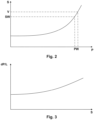
- Fig. 2 shows schematically such a relationship between the actuation parameter P and the damage S.
- Such a relationship can be linear, but must be like the one in Fig. 2 shown may not be the case.
- the damage S may increase more or less than the actuation parameter P.
- the damage S of component K can be determined directly via the actuation parameter P.
- a value of the actuation parameter P can be determined at which a function F of the system can no longer be guaranteed. This value thus corresponds to a failure damage extent V of the component K.
- a maintenance value PW of the actuation parameter P can be defined, whereby reaching This maintenance value PW can trigger a maintenance M, which may include a replacement of component K.
- This maintenance value PW is as in Fig. 2 clearly lower than the value of the actuation parameter P in a case of damage in which the damage S reaches a failure damage extent V.
- This maintenance value PW corresponds to a maintenance extent SW of the damage S of the component K, which is lower than the failure damage extent V, so that when maintenance M is initiated when this maintenance extent SW is reached, there is still sufficient time for replacement and an unplanned downtime can be avoided.
- Fig. 3 shows a relationship between a change in the actuation parameter P and a change in the load spectrum via a damage S of the component K.
- a non-linearity can also be present here or a corresponding relationship can be such that the component K, with a constant load L, requires a greater change in the actuation parameter P depending on a damage state in order to be able to maintain a function F.
- Using a corresponding relationship it is easy to deduce actual damage S and, if applicable, a remaining service life by continuously measuring the actuation parameter P on the one hand and the load L on the other, even if no direct relationship between the actuation parameter P and the extent of damage has yet been determined.
- a supplementary measurement of the load L or a recording of a load spectrum and comparison of this with the course of the actuation parameter P can therefore also be used to plan maintenance measures.
- a relationship between different loads and damage S of component K can be easily determined in this way, in order to be able to use this relationship for a remaining service life estimate.
- the method according to the invention can be used for a wide variety of mechatronic systems.
- condition-based maintenance M can then be carried out in good time before an unplanned downtime.
Landscapes
- Physics & Mathematics (AREA)
- General Physics & Mathematics (AREA)
- Engineering & Computer Science (AREA)
- Automation & Control Theory (AREA)
- Testing Of Devices, Machine Parts, Or Other Structures Thereof (AREA)
- Combined Controls Of Internal Combustion Engines (AREA)
- Electrical Control Of Air Or Fuel Supplied To Internal-Combustion Engine (AREA)
Claims (7)
- Procédé de détermination d'une étendue d'un endommagement (S) d'un composant (K) d'un système mécatronique, lequel système comporte un dispositif de compensation (C) pour compenser la conséquence de l'endommagement (S) du composant (K), de telle manière qu'une fonction réelle (F) du système mécatronique peut être maintenue même à une étendue de l'endommagement (S) du composant (K), qui est plus faible qu'une étendue d'endommagement de défaillance (V), sachant que le dispositif de compensation (C) est agencé pour influencer un actionnement (B) du composant ainsi que pour la saisie d'une fonction réelle (Fi) du système et pour la mémorisation d'un paramètre d'actionnement (P) correspondant à l'actionnement (B) pour influencer l'actionnement (B) du composant (K) lors d'un écart de la fonction réelle (Fi) d'une fonction théorique (Fs), lequel écart est causé par un endommagement croissant (S) du composant (K) et dépasse une tolérance prédéfinie, de telle manière que la fonction réelle (Fi) correspond à nouveau à la fonction théorique (Fs) et pour mémoriser ensuite l'actionnement modifié (B) dans le paramètre d'actionnement (P), sachant que ce paramètre d'actionnement (P) forme la base pour des actionnements ultérieurs (B), sachant que l'étendue de l'endommagement (S) est déterminée au moyen du paramètre d'actionnement (P).
- Procédé selon la revendication 1, caractérisé en ce qu'un profil temporel du paramètre d'actionnement (P) est mémorisé et une étendue de l'endommagement (S) est déterminée en se basant sur une variation temporelle du paramètre d'actionnement (P).
- Procédé selon la revendication 1 ou 2, caractérisé en ce qu'un profil temporel d'une sollicitation du composant (K) et un profil temporel du paramètre d'actionnement (P) sont mémorisés, sachant que l'étendue de l'endommagement (S) est déterminée à l'intérieur d'une période de temps définie au moyen d'une modification du paramètre d'actionnement (P) par rapport à une sollicitation cumulée du composant (K).
- Procédé selon l'une quelconque des revendications 1 à 3, caractérisé en ce que l'endommagement (S) est déterminé à l'aide du paramètre d'endommagement (P) au moyen d'un rapport existant entre le paramètre d'actionnement (P) et l'endommagement (S), lequel a été préalablement déterminé par calcul et/ou par des essais.
- Procédé selon l'une quelconque des revendications 1 à 4, caractérisé en ce qu'une durée de vie résiduelle du système est déterminée au moyen d'un rapport existant entre le paramètre d'actionnement (P) et l'endommagement (S), lequel a été préalablement déterminé par calcul et/ou par des essais.
- Procédé d'entretien d'un système mécatronique, sachant qu'une étendue d'un endommagement (S) d'un composant (K) du système est déterminée dans un procédé selon l'une quelconque des revendications 1 à 5, sachant qu'un entretien (M) est exécuté, lorsque l'endommagement (S) dépasse une étendue d'entretien (SW) prédéfinie.
- Procédé selon l'une quelconque des revendications 1 à 6, caractérisé en ce que le procédé pour l'entretien (M) d'une installation éolienne ou d'un véhicule est mis en œuvre.
Applications Claiming Priority (1)
| Application Number | Priority Date | Filing Date | Title |
|---|---|---|---|
| ATA51011/2020A AT524471B1 (de) | 2020-11-18 | 2020-11-18 | Verfahren zur Bestimmung eines Schädigungsausmaßes |
Publications (3)
| Publication Number | Publication Date |
|---|---|
| EP4002039A1 EP4002039A1 (fr) | 2022-05-25 |
| EP4002039B1 true EP4002039B1 (fr) | 2025-06-11 |
| EP4002039C0 EP4002039C0 (fr) | 2025-06-11 |
Family
ID=77518946
Family Applications (1)
| Application Number | Title | Priority Date | Filing Date |
|---|---|---|---|
| EP21193150.6A Active EP4002039B1 (fr) | 2020-11-18 | 2021-08-26 | Procédé de détermination de l'étendue de dommages |
Country Status (2)
| Country | Link |
|---|---|
| EP (1) | EP4002039B1 (fr) |
| AT (1) | AT524471B1 (fr) |
Families Citing this family (1)
| Publication number | Priority date | Publication date | Assignee | Title |
|---|---|---|---|---|
| CN120864371B (zh) * | 2025-07-24 | 2026-02-10 | 河南省矿山起重机有限公司 | 一种起重机运行状态健康监测系统及方法 |
Family Cites Families (7)
| Publication number | Priority date | Publication date | Assignee | Title |
|---|---|---|---|---|
| DE10257793A1 (de) * | 2002-12-11 | 2004-07-22 | Daimlerchrysler Ag | Modellbasierter Lebensdauerbeobachter |
| DE102005025520A1 (de) * | 2005-06-03 | 2006-12-07 | Robert Bosch Gmbh | Verfahren zur modellbasierten Diagnose eines mechatronischen Systems |
| US8116990B2 (en) * | 2007-10-19 | 2012-02-14 | Ashok Koul | Method and system for real-time prognosis analysis and usage based residual life assessment of turbine engine components and display |
| US20120283963A1 (en) * | 2011-05-05 | 2012-11-08 | Mitchell David J | Method for predicting a remaining useful life of an engine and components thereof |
| DE102013211543A1 (de) * | 2013-06-19 | 2014-12-24 | Robert Bosch Gmbh | Verfahren zum alterungs- und energieeffizienten Betrieb insbesondere eines Kraftfahrzeugs |
| AT514683B1 (de) * | 2013-10-11 | 2015-03-15 | Avl List Gmbh | Verfahren zur Abschätzung der Schädigung zumindest eines technischen Bauteiles einer Brennkraftmaschine |
| DE102018214099A1 (de) * | 2018-08-21 | 2020-02-27 | Zf Friedrichshafen Ag | Verfahren und System zur unmittelbaren Ermittlung einer theoretischen Schädigung mindestens einer Komponente einer Vorrichtung |
-
2020
- 2020-11-18 AT ATA51011/2020A patent/AT524471B1/de active
-
2021
- 2021-08-26 EP EP21193150.6A patent/EP4002039B1/fr active Active
Also Published As
| Publication number | Publication date |
|---|---|
| EP4002039A1 (fr) | 2022-05-25 |
| AT524471A1 (de) | 2022-06-15 |
| EP4002039C0 (fr) | 2025-06-11 |
| AT524471B1 (de) | 2022-09-15 |
Similar Documents
| Publication | Publication Date | Title |
|---|---|---|
| EP1828719B1 (fr) | Procede pour surveiller le fonctionnement d'un capteur | |
| DE102011008561A1 (de) | Funktionsüberwachtes Führungssystem zur Verstellung zumindest einer Systemkomponente sowie Verfahren zur Funktionsüberwachung eines solchen Führungssystems | |
| EP3454071B1 (fr) | Procédé de surveillance de la fonction d'un système de refroidissement d'un dispositif de résonance magnétique, dispositif de résonance magnétique, programme informatique et support de données lisible de manière électronique | |
| DE112015001924B4 (de) | Motorsteuereinrichtung | |
| DE102011115244A1 (de) | Verfahren und System zur Überwachung des Betriebszustands einer Pumpe | |
| EP3033513A1 (fr) | Procédé permettant le diagnostic pour chaque injecteur d'un dispositif d'injection de carburant et moteur à combustion interne pourvu d'un dispositif d'injection de carburant | |
| EP4002039B1 (fr) | Procédé de détermination de l'étendue de dommages | |
| EP4381266A1 (fr) | Procédé et dispositif de détermination de la durée de vie restante de mécanisme d'engrenage | |
| EP2067080B1 (fr) | Procédé pour faire fonctionner une installation industrielle, et système de guidage correspondant | |
| EP3353798B1 (fr) | Unité de commande ainsi que procédé de surveillance du fonctionnement d'un actionneur électromagnétique | |
| EP3358332B1 (fr) | Procédé de détermination de début d'une vie utile résiduelle en fonction d'un composant à déformation élastique comme une pièce structurelle et/ou pièce de support d'un appareil | |
| EP4348825A1 (fr) | Procédé et dispositif de surveillance pour surveiller l'état d'une machine | |
| EP3891368B1 (fr) | Procédé permettant de déterminer et de prédire la périodicité individuelle des vidanges d'un moteur à combustion interne | |
| WO2008128598A1 (fr) | Procédé de diagnostic de systèmes techniques, en particulier pour véhicule automobile | |
| EP1189126A2 (fr) | Procédé de surveillance d'une installation | |
| WO2024246127A1 (fr) | Procédé pour déterminer au moins un paramètre de fonctionnement d'un système de pile à combustible en fonctionnement pour un véhicule automobile, système de pile à combustible, produit-programme d'ordinateur et support lisible par ordinateur | |
| DE102018205311B4 (de) | Diagnoseeinrichtung, System und Verfahren | |
| DE102018104665B4 (de) | Verfahren zum Betrieb einer Brennkraftmaschine, Steuereinrichtung und Brennkraftmaschine | |
| EP4057094B1 (fr) | Procédé de détermination du début d'une durée d'utilité résiduelle de composant dépendant de l'usure d'un composant déformable de manière élastique, en tant que partie structurale et/ou partie de palier d'un appareil | |
| EP3864279B1 (fr) | Méthode pour détecter et prédire l'encrassement d'un refroidisseur rge dans un moteur diesel à combustion | |
| WO2019242876A1 (fr) | Procédé de détection d'usure et de pronostic prédictif d'usure d'actionneurs électromécaniques par rapport au temps de fonctionnement d'une machine à moteur à combustion interne | |
| DE102021207800A1 (de) | Verfahren, Recheneinheit und Computerprogramm zum Einstellen eines Betriebsparameters in einer technischen Anlage | |
| DE102021118296B4 (de) | Verfahren zur Driftkompensation eines Drucksensors und Drucksensor | |
| AT528105B1 (de) | Verfahren zur Ausfallprognose von Prüfanlagen | |
| WO2019166377A1 (fr) | Procédé servant à faire fonctionner un moteur à combustion interne, dispositif de commande et moteur à combustion interne |
Legal Events
| Date | Code | Title | Description |
|---|---|---|---|
| PUAI | Public reference made under article 153(3) epc to a published international application that has entered the european phase |
Free format text: ORIGINAL CODE: 0009012 |
|
| STAA | Information on the status of an ep patent application or granted ep patent |
Free format text: STATUS: THE APPLICATION HAS BEEN PUBLISHED |
|
| AK | Designated contracting states |
Kind code of ref document: A1 Designated state(s): AL AT BE BG CH CY CZ DE DK EE ES FI FR GB GR HR HU IE IS IT LI LT LU LV MC MK MT NL NO PL PT RO RS SE SI SK SM TR |
|
| STAA | Information on the status of an ep patent application or granted ep patent |
Free format text: STATUS: REQUEST FOR EXAMINATION WAS MADE |
|
| 17P | Request for examination filed |
Effective date: 20221123 |
|
| RBV | Designated contracting states (corrected) |
Designated state(s): AL AT BE BG CH CY CZ DE DK EE ES FI FR GB GR HR HU IE IS IT LI LT LU LV MC MK MT NL NO PL PT RO RS SE SI SK SM TR |
|
| STAA | Information on the status of an ep patent application or granted ep patent |
Free format text: STATUS: EXAMINATION IS IN PROGRESS |
|
| 17Q | First examination report despatched |
Effective date: 20230921 |
|
| GRAP | Despatch of communication of intention to grant a patent |
Free format text: ORIGINAL CODE: EPIDOSNIGR1 |
|
| STAA | Information on the status of an ep patent application or granted ep patent |
Free format text: STATUS: GRANT OF PATENT IS INTENDED |
|
| GRAS | Grant fee paid |
Free format text: ORIGINAL CODE: EPIDOSNIGR3 |
|
| GRAA | (expected) grant |
Free format text: ORIGINAL CODE: 0009210 |
|
| STAA | Information on the status of an ep patent application or granted ep patent |
Free format text: STATUS: THE PATENT HAS BEEN GRANTED |
|
| INTG | Intention to grant announced |
Effective date: 20250410 |
|
| AK | Designated contracting states |
Kind code of ref document: B1 Designated state(s): AL AT BE BG CH CY CZ DE DK EE ES FI FR GB GR HR HU IE IS IT LI LT LU LV MC MK MT NL NO PL PT RO RS SE SI SK SM TR |
|
| REG | Reference to a national code |
Ref country code: GB Ref legal event code: FG4D Free format text: NOT ENGLISH |
|
| REG | Reference to a national code |
Ref country code: CH Ref legal event code: EP |
|
| REG | Reference to a national code |
Ref country code: IE Ref legal event code: FG4D Free format text: LANGUAGE OF EP DOCUMENT: GERMAN |
|
| U01 | Request for unitary effect filed |
Effective date: 20250611 |
|
| U07 | Unitary effect registered |
Designated state(s): AT BE BG DE DK EE FI FR IT LT LU LV MT NL PT RO SE SI Effective date: 20250617 |
|
| U20 | Renewal fee for the european patent with unitary effect paid |
Year of fee payment: 5 Effective date: 20250703 |
|
| PG25 | Lapsed in a contracting state [announced via postgrant information from national office to epo] |
Ref country code: ES Free format text: LAPSE BECAUSE OF FAILURE TO SUBMIT A TRANSLATION OF THE DESCRIPTION OR TO PAY THE FEE WITHIN THE PRESCRIBED TIME-LIMIT Effective date: 20250611 |
|
| PG25 | Lapsed in a contracting state [announced via postgrant information from national office to epo] |
Ref country code: NO Free format text: LAPSE BECAUSE OF FAILURE TO SUBMIT A TRANSLATION OF THE DESCRIPTION OR TO PAY THE FEE WITHIN THE PRESCRIBED TIME-LIMIT Effective date: 20250911 Ref country code: GR Free format text: LAPSE BECAUSE OF FAILURE TO SUBMIT A TRANSLATION OF THE DESCRIPTION OR TO PAY THE FEE WITHIN THE PRESCRIBED TIME-LIMIT Effective date: 20250912 |
|
| PG25 | Lapsed in a contracting state [announced via postgrant information from national office to epo] |
Ref country code: HR Free format text: LAPSE BECAUSE OF FAILURE TO SUBMIT A TRANSLATION OF THE DESCRIPTION OR TO PAY THE FEE WITHIN THE PRESCRIBED TIME-LIMIT Effective date: 20250611 |
|
| PG25 | Lapsed in a contracting state [announced via postgrant information from national office to epo] |
Ref country code: RS Free format text: LAPSE BECAUSE OF FAILURE TO SUBMIT A TRANSLATION OF THE DESCRIPTION OR TO PAY THE FEE WITHIN THE PRESCRIBED TIME-LIMIT Effective date: 20250911 |
|
| PG25 | Lapsed in a contracting state [announced via postgrant information from national office to epo] |
Ref country code: IS Free format text: LAPSE BECAUSE OF FAILURE TO SUBMIT A TRANSLATION OF THE DESCRIPTION OR TO PAY THE FEE WITHIN THE PRESCRIBED TIME-LIMIT Effective date: 20251011 |
|
| PG25 | Lapsed in a contracting state [announced via postgrant information from national office to epo] |
Ref country code: SM Free format text: LAPSE BECAUSE OF FAILURE TO SUBMIT A TRANSLATION OF THE DESCRIPTION OR TO PAY THE FEE WITHIN THE PRESCRIBED TIME-LIMIT Effective date: 20250611 |
|
| PG25 | Lapsed in a contracting state [announced via postgrant information from national office to epo] |
Ref country code: CZ Free format text: LAPSE BECAUSE OF FAILURE TO SUBMIT A TRANSLATION OF THE DESCRIPTION OR TO PAY THE FEE WITHIN THE PRESCRIBED TIME-LIMIT Effective date: 20250611 |
|
| PG25 | Lapsed in a contracting state [announced via postgrant information from national office to epo] |
Ref country code: PL Free format text: LAPSE BECAUSE OF FAILURE TO SUBMIT A TRANSLATION OF THE DESCRIPTION OR TO PAY THE FEE WITHIN THE PRESCRIBED TIME-LIMIT Effective date: 20250611 |
|
| PG25 | Lapsed in a contracting state [announced via postgrant information from national office to epo] |
Ref country code: SK Free format text: LAPSE BECAUSE OF FAILURE TO SUBMIT A TRANSLATION OF THE DESCRIPTION OR TO PAY THE FEE WITHIN THE PRESCRIBED TIME-LIMIT Effective date: 20250611 |
|
| REG | Reference to a national code |
Ref country code: CH Ref legal event code: H13 Free format text: ST27 STATUS EVENT CODE: U-0-0-H10-H13 (AS PROVIDED BY THE NATIONAL OFFICE) Effective date: 20260324 |
|
| PG25 | Lapsed in a contracting state [announced via postgrant information from national office to epo] |
Ref country code: MC Free format text: LAPSE BECAUSE OF FAILURE TO SUBMIT A TRANSLATION OF THE DESCRIPTION OR TO PAY THE FEE WITHIN THE PRESCRIBED TIME-LIMIT Effective date: 20250611 |
|
| PLBE | No opposition filed within time limit |
Free format text: ORIGINAL CODE: 0009261 |
|
| STAA | Information on the status of an ep patent application or granted ep patent |
Free format text: STATUS: NO OPPOSITION FILED WITHIN TIME LIMIT |
|
| PG25 | Lapsed in a contracting state [announced via postgrant information from national office to epo] |
Ref country code: CH Free format text: LAPSE BECAUSE OF NON-PAYMENT OF DUE FEES Effective date: 20250831 |
|
| REG | Reference to a national code |
Ref country code: CH Ref legal event code: L10 Free format text: ST27 STATUS EVENT CODE: U-0-0-L10-L00 (AS PROVIDED BY THE NATIONAL OFFICE) Effective date: 20260423 |