EP4002041A1 - Procédé de surveillance prédictive d'une variable d'un milieu et d'une précision de mesure d'un dispositif de mesure de cette variable - Google Patents
Procédé de surveillance prédictive d'une variable d'un milieu et d'une précision de mesure d'un dispositif de mesure de cette variable Download PDFInfo
- Publication number
- EP4002041A1 EP4002041A1 EP21196403.6A EP21196403A EP4002041A1 EP 4002041 A1 EP4002041 A1 EP 4002041A1 EP 21196403 A EP21196403 A EP 21196403A EP 4002041 A1 EP4002041 A1 EP 4002041A1
- Authority
- EP
- European Patent Office
- Prior art keywords
- compliancy
- measured values
- measured
- specific operation
- during
- Prior art date
- Legal status (The legal status is an assumption and is not a legal conclusion. Google has not performed a legal analysis and makes no representation as to the accuracy of the status listed.)
- Granted
Links
Images
Classifications
-
- G—PHYSICS
- G05—CONTROLLING; REGULATING
- G05B—CONTROL OR REGULATING SYSTEMS IN GENERAL; FUNCTIONAL ELEMENTS OF SUCH SYSTEMS; MONITORING OR TESTING ARRANGEMENTS FOR SUCH SYSTEMS OR ELEMENTS
- G05B23/00—Testing or monitoring of control systems or parts thereof
- G05B23/02—Electric testing or monitoring
- G05B23/0205—Electric testing or monitoring by means of a monitoring system capable of detecting and responding to faults
- G05B23/0218—Electric testing or monitoring by means of a monitoring system capable of detecting and responding to faults characterised by the fault detection method dealing with either existing or incipient faults
- G05B23/0221—Preprocessing measurements, e.g. data collection rate adjustment; Standardization of measurements; Time series or signal analysis, e.g. frequency analysis or wavelets; Trustworthiness of measurements; Indexes therefor; Measurements using easily measured parameters to estimate parameters difficult to measure; Virtual sensor creation; De-noising; Sensor fusion; Unconventional preprocessing inherently present in specific fault detection methods like PCA-based methods
-
- G—PHYSICS
- G01—MEASURING; TESTING
- G01N—INVESTIGATING OR ANALYSING MATERIALS BY DETERMINING THEIR CHEMICAL OR PHYSICAL PROPERTIES
- G01N27/00—Investigating or analysing materials by the use of electric, electrochemical, or magnetic means
- G01N27/26—Investigating or analysing materials by the use of electric, electrochemical, or magnetic means by investigating electrochemical variables; by using electrolysis or electrophoresis
- G01N27/27—Association of two or more measuring systems or cells, each measuring a different parameter, where the measurement results may be either used independently, the systems or cells being physically associated, or combined to produce a value for a further parameter
-
- G—PHYSICS
- G01—MEASURING; TESTING
- G01F—MEASURING VOLUME, VOLUME FLOW, MASS FLOW OR LIQUID LEVEL; METERING BY VOLUME
- G01F23/00—Indicating or measuring liquid level or level of fluent solid material, e.g. indicating in terms of volume or indicating by means of an alarm
- G01F23/22—Indicating or measuring liquid level or level of fluent solid material, e.g. indicating in terms of volume or indicating by means of an alarm by measuring physical variables, other than linear dimensions, pressure or weight, dependent on the level to be measured, e.g. by difference of heat transfer of steam or water
-
- G—PHYSICS
- G01—MEASURING; TESTING
- G01F—MEASURING VOLUME, VOLUME FLOW, MASS FLOW OR LIQUID LEVEL; METERING BY VOLUME
- G01F1/00—Measuring the volume flow or mass flow of fluid or fluent solid material wherein the fluid passes through a meter in a continuous flow
-
- G—PHYSICS
- G01—MEASURING; TESTING
- G01F—MEASURING VOLUME, VOLUME FLOW, MASS FLOW OR LIQUID LEVEL; METERING BY VOLUME
- G01F23/00—Indicating or measuring liquid level or level of fluent solid material, e.g. indicating in terms of volume or indicating by means of an alarm
- G01F23/22—Indicating or measuring liquid level or level of fluent solid material, e.g. indicating in terms of volume or indicating by means of an alarm by measuring physical variables, other than linear dimensions, pressure or weight, dependent on the level to be measured, e.g. by difference of heat transfer of steam or water
- G01F23/24—Indicating or measuring liquid level or level of fluent solid material, e.g. indicating in terms of volume or indicating by means of an alarm by measuring physical variables, other than linear dimensions, pressure or weight, dependent on the level to be measured, e.g. by difference of heat transfer of steam or water by measuring variations of resistance of resistors due to contact with conductor fluid
-
- G—PHYSICS
- G01—MEASURING; TESTING
- G01K—MEASURING TEMPERATURE; MEASURING QUANTITY OF HEAT; THERMALLY-SENSITIVE ELEMENTS NOT OTHERWISE PROVIDED FOR
- G01K13/00—Thermometers specially adapted for specific purposes
-
- G—PHYSICS
- G01—MEASURING; TESTING
- G01N—INVESTIGATING OR ANALYSING MATERIALS BY DETERMINING THEIR CHEMICAL OR PHYSICAL PROPERTIES
- G01N27/00—Investigating or analysing materials by the use of electric, electrochemical, or magnetic means
- G01N27/02—Investigating or analysing materials by the use of electric, electrochemical, or magnetic means by investigating impedance
-
- G—PHYSICS
- G01—MEASURING; TESTING
- G01N—INVESTIGATING OR ANALYSING MATERIALS BY DETERMINING THEIR CHEMICAL OR PHYSICAL PROPERTIES
- G01N27/00—Investigating or analysing materials by the use of electric, electrochemical, or magnetic means
- G01N27/02—Investigating or analysing materials by the use of electric, electrochemical, or magnetic means by investigating impedance
- G01N27/04—Investigating or analysing materials by the use of electric, electrochemical, or magnetic means by investigating impedance by investigating resistance
- G01N27/06—Investigating or analysing materials by the use of electric, electrochemical, or magnetic means by investigating impedance by investigating resistance of a liquid
-
- G—PHYSICS
- G01—MEASURING; TESTING
- G01N—INVESTIGATING OR ANALYSING MATERIALS BY DETERMINING THEIR CHEMICAL OR PHYSICAL PROPERTIES
- G01N27/00—Investigating or analysing materials by the use of electric, electrochemical, or magnetic means
- G01N27/26—Investigating or analysing materials by the use of electric, electrochemical, or magnetic means by investigating electrochemical variables; by using electrolysis or electrophoresis
- G01N27/28—Electrolytic cell components
- G01N27/30—Electrodes, e.g. test electrodes; Half-cells
- G01N27/302—Electrodes, e.g. test electrodes; Half-cells pH sensitive, e.g. quinhydron, antimony or hydrogen electrodes
-
- G—PHYSICS
- G01—MEASURING; TESTING
- G01N—INVESTIGATING OR ANALYSING MATERIALS BY DETERMINING THEIR CHEMICAL OR PHYSICAL PROPERTIES
- G01N27/00—Investigating or analysing materials by the use of electric, electrochemical, or magnetic means
- G01N27/26—Investigating or analysing materials by the use of electric, electrochemical, or magnetic means by investigating electrochemical variables; by using electrolysis or electrophoresis
- G01N27/28—Electrolytic cell components
- G01N27/30—Electrodes, e.g. test electrodes; Half-cells
- G01N27/333—Ion-selective electrodes or membranes
-
- G—PHYSICS
- G05—CONTROLLING; REGULATING
- G05B—CONTROL OR REGULATING SYSTEMS IN GENERAL; FUNCTIONAL ELEMENTS OF SUCH SYSTEMS; MONITORING OR TESTING ARRANGEMENTS FOR SUCH SYSTEMS OR ELEMENTS
- G05B23/00—Testing or monitoring of control systems or parts thereof
- G05B23/02—Electric testing or monitoring
- G05B23/0205—Electric testing or monitoring by means of a monitoring system capable of detecting and responding to faults
- G05B23/0259—Electric testing or monitoring by means of a monitoring system capable of detecting and responding to faults characterized by the response to fault detection
- G05B23/0283—Predictive maintenance, e.g. involving the monitoring of a system and, based on the monitoring results, taking decisions on the maintenance schedule of the monitored system; Estimating remaining useful life [RUL]
-
- G—PHYSICS
- G16—INFORMATION AND COMMUNICATION TECHNOLOGY [ICT] SPECIALLY ADAPTED FOR SPECIFIC APPLICATION FIELDS
- G16C—COMPUTATIONAL CHEMISTRY; CHEMOINFORMATICS; COMPUTATIONAL MATERIALS SCIENCE
- G16C60/00—Computational materials science, i.e. ICT specially adapted for investigating the physical or chemical properties of materials or phenomena associated with their design, synthesis, processing, characterisation or utilisation
Definitions
- the invention concerns a method of predictive monitoring of a variable of a medium located in a container of a facility and of a measurement accuracy of a measurement device measuring this variable during operation of the facility.
- Measurement devices measuring a variable of a medium located inside a container are used on various types of facilities, like e.g. facilities repeatedly performing a predefined batch process, facilities of industrial plants, like e.g. production plants performing production processes, facilities of chemical plants, facilities of biotechnological plants designed to perform a biotechnological process and laboratory facilities.
- Measurement devices applied in these applications comprise various types of devices, like e.g. level measurement devices measuring a level of a medium in a container, flow meters measuring a flow of a medium flowing through a pipe, temperature measurement devices measuring a temperature of a medium, pressure measurement devices measuring pressure of a medium, as well as measurement devices, like e.g. amperometric, potentiometric, photometric or spectrometric measurement devices measuring a pH-value of the medium or a concentration of an analyte contained in the medium.
- measurement instruments comprise measurement instruments providing measurement results applied to regulate and/or to control the operation of the facility, as well as measurement instruments providing measured values, which are neither applied to regulate nor to control the operation of the facility.
- measurement instrument is used as generic term for any instruments providing measurement results and the subgroup of measurement instruments providing measured values, which are neither applied to regulate nor to control the operation of the facility are called measurement devices. Examples of measurement devices are e.g. measurement devices applied to monitor the variable measured by them, as well as measurement device applied to confirm that the variable of the medium, like e.g.
- a medium given by an intermediate or end product produced on the facility is compliant to a specified requirement.
- theses measurement devices are neither applied to regulate nor to control the operation of the facility, they nonetheless play a vital part, e.g. in monitoring the operation of the facility and/or in ensuring and/or confirming adherence to predetermined quality standards.
- non-compliancy of a measurement device to a specified measurement accuracy may have severe consequences, ranging from impaired production processes, the production and/or the sale of faulty products to potential hazards to people and/or the environment.
- Measurement properties, in particular the measurement accuracy, of measurement instruments can change over time, e.g. due to aging and/or due to an exposure of the measurement instrument to harsh conditions. To ensure proper operation of measurement instruments they are regularly calibrated and subsequently repaired, adjusted or replaced, in case they are found to no longer comply to the measurement accuracy specified for them during calibration. During calibrations non-compliancy is e.g. determined when a measurement error of the measurement instrument determined during calibration exceeds a maximum permissible error.
- Calibrations are not only time and cost intensive but usually also require for the measurement instruments to be removed from the process.
- calibration of a pH- measurement instruments comprising a measuring cell closed off by an H+ ion-selective membrane usually requires for the measuring cell to be immersed in a reference solution, like e.g. a buffer solution, such that an outside surface of the membrane is exposed to the reference solution.
- removal of the measurement instrument requires for the operation of the facility to be interrupted. This is especially disadvantageous on facilities, like e.g. facilities performing chemical or biotechnological methods or processes, where high standards of hygiene or even sterility have to be ensured. Even when a calibration does not require an interruption of the operation of the facility, it still causes the problem, that the measurement instrument cannot perform measurements at the facility whilst it is being calibrated.
- EP 2 602 680 B1 describes a method of determining an optimized next calibration time, at which a specific measurement instrument requires re-calibration.
- This next calibration time is determined based on a Monte Carlo simulation performed based on the measurement errors of the measurement instrument determined during at least two previously performed calibrations and probability density functions for determining a measurement error in the respective calibration solely due to an uncertainty inherent to the respective calibration.
- This method does however require two previously performed calibrations, as well as the uncertainty inherent to the calibrations, which may not always be available.
- a method of operating a measurement instrument measuring a variable at an operating site and of predictive monitoring of a compliancy of at least one characteristic of the measurement instrument to a requirement specified for the measurement instrument is described in European Patent application No. 20168733.2 filed on April 8, 2020 .
- This method is performed based on continuously monitored deviations between measured values determined by the measurement instrument and corresponding reference values. Based on the deviations a remaining time remaining until the deviations will exceed a deviation range defined for the deviations is determined based on a method of time series forecasting. Because this method is performed based on deviations between the monitored variable and corresponding reference values, it can only be applied, when corresponding reference values are available.
- the invention comprises a method, in particular a computer implemented method, of predictive monitoring of a variable of a medium located in a container of a facility and of a measurement accuracy of a measurement device measuring this variable and providing measured values of this variable during operation of the facility, wherein the facility is operated independently of the measured values and wherein operation of the facility comprises a repeatedly occurring specific operation phase, wherein measured values measured during the specific operation phases exhibit a characteristic distinguishing these measured values from measured values measured during other time periods, and wherein the characteristic is compliant to a reference characteristic when the facility was operating properly and the measurement device was compliant to a specified measurement accuracy during the respective specific operation phase, this method comprising the steps of:
- This method provides the advantages, that it can be performed during operation of the facility, that the measured values measured by the measurement device are available during performance of the method, and that it does not require reference measurements of the variable.
- the method provides the advantage, that an identification of the specific operation phase, the determination of the characteristic and the reference characteristic, as well as the determination of the classification method can be performed solely based on the training data without any prior knowledge about the specific operation phase. Thus, neither prior knowledge about the facility and the operation of the facility, nor reference measurements of the variable are required to perform the method.
- the predictive monitoring not only detects impairments caused by impaired measurement properties of the measurement device but also impairments caused by an impaired operation of the facility affecting the true value of the variable during the specific operation phases.
- the method further comprises the steps of:
- this method comprising at least one of the steps of:
- the training data is labeled training data comprising the measured values and the respective operation phase, during which they were measured, and at least one of the steps of: identifying the specific operation phase, determining the characteristic, determining the reference characteristic and determining the classification method is performed by performing a method of supervised learning.
- the method additionally comprises the step of determining and discarding at least one of: potentially polluted measured values and potentially polluted measured values given by edge values measured at the beginning and at the end of the specific operation phase comprised in the identified data sets before determining the time series.
- the method comprises the step of providing the continuously recorded data to a calculating unit, wherein the calculating unit: is embodied to perform, trained to perform and/or designed to learn and to perform at least one of: identifying the specific operation phase and determining the classification method based on the data provided to it; determines and performs the classification method based on the data provided to it; determines the time series; and/or determines the remaining time.
- the facility is embodied to perform a predetermined task or a predetermined process and/or or to repeatedly perform a predetermined batch process; and/or the measurement device is an electrochemical measurement device measuring a concentration of an analyte contained in the medium or a pH-sensor measuring a pH-value of the medium.
- the measurement device measures at least one parameter; the continuously recorded data includes measured parameter values of the parameter(s) measured and provided by the measurement device and their time of measurement; and at least one of: identifying the specific operation phase, determining the characteristic, determining the reference characteristic, determining the classification method, performing the classification method and determining the time series is performed based on the measured values and the measured parameter values included in the training data.
- the at least one parameter include at least one of:
- each remaining time is determined by performing a method of time series forecasting or by performing a method of time series forecasting comprising the steps of:
- the method comprises the steps of:
- the method comprises the steps of:
- the invention concerns a method, in particular a computer implemented method, of predictive monitoring of a variable of a medium 5 located in a container 1 of a facility and of a measurement accuracy of a measurement device 3 measuring this variable and providing measured values m(ti) of this variable during operation of the facility, wherein the facility is operated independently of the measured values m(ti) and wherein operation of the facility comprises a repeatedly occurring specific operation phase Ps, wherein measured values m(ti) measured during the specific operation phases Ps exhibit a characteristic C distinguishing these measured values m(ti) from measured values measured m(ti) during other time periods, and wherein the characteristic C is compliant to a reference characteristic Cr when the facility was operating properly and the measurement device 3 was compliant to a specified measurement accuracy during the respective specific operation phase Ps.
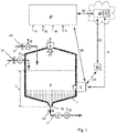
- Fig. 1 shows an example of a facility designed to repeatedly perform a predetermined batch process.
- the container 1 is a tank, like e.g. a bioreactor, and the measurement device 3 is installed on the container 1 and measures the variable of the medium 5 comprised in the container 1.
- the invention is not limited to facilities performing batch processes.
- the facility can be another type of facility, like e.g. a facility designed to perform at least one given task, like e.g. a facility of a production plant performing a production process, a facility of a chemical plant, a facility of a biotechnological plant, or a facility of a laboratory, like e.g. a facility performing laboratory analyses.
- the container 1 does not have to be a tank.
- the method can be applied in the same way, with respect to a measurement device installed on another type of container having an interior containing the medium.
- Examples are open or closed vessels, as well as pipes including the medium located inside the pipe and/or flowing through the pipe.
- the method can e.g. be applied in the same way, with respect to the measurement device 3', indicated by dotted lines in Fig. 1 , installed in or on one of the pipes 7 connected to the tank.
- the measurement device 3 is e.g. an electrochemical sensor, e.g. a potentiometric sensor measuring an activity or a concentration of an analyte comprised in the medium 5 or a pH-value of the medium 5.
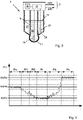
- An example of an electrochemical sensor, like e.g. a pH-sensor is shown in Fig. 2 .
- This sensor includes a measuring cell 9 closed off by an ion-selective membrane 11, like e.g. H + -ion selective membrane, having an inside surface exposed to an electrolyte 13 located inside the measuring cell 9, like e.g. a pH buffer solution, and an outside surface exposed to the medium 5 surrounding it.
- an electric potential Uel corresponding to the variable to be measured can be derived via a measuring electrode 15 extending into the electrolyte 13.
- the measuring electrode 15 is connected to measurement electronics 17 embodied to quantitatively determine the variable based on the electrode potential Uel provided by the measuring electrode 15 or based on a difference between the electrode potential Uel and a reference potential Uref.
- the reference potential Uref is e.g. a potential provided by a reference cell 19.
- the reference cell 19 included an electrolyte 21 located inside the reference cell 19, a reference electrode 23 extending into this electrolyte 21 and a diaphragm 25 permeable to charge carriers.
- the diaphragm 25 is inserted into a wall section of an outside wall of the reference cell 19 such that an inner surface of the diaphragm 25 is exposed to the electrolyte 21 located inside the reference cell 19 and an outer surface of the diaphragm 25 is exposed to the medium 5 surrounding it.
- the invention is not limited to pH-sensors.
- the measurement device 3 can e.g. be another type of measurement device and/or a measurement device measuring another variable, like e.g. a pressure or a turbidity, of the medium 5 comprised in the container 1.
- operation of the facility shown in Fig. 1 e.g. comprises repeated performances of a batch process, like e.g. a batch process producing a batch of a product, like e.g. a protein or lemonade, comprising a sequence of operation phases.
- a batch process like e.g. a batch process producing a batch of a product, like e.g. a protein or lemonade, comprising a sequence of operation phases.
- the sequence e.g. comprises:
- operation of the facility may additionally include a repeatedly performed cleaning phase Pc, during which the container 1 is cleaned with a cleaning agent.
- the cleaning phases Pc can e.g. be performed in between consecutively performed batch processes, like e.g. after each discharging phase Pd.
- operation of the facility is performed independently of the measured values m(ti) measured by the measurement device 3.
- operation of the facility is neither regulated nor controlled based on the measured values m(ti) measured by the measurement device 3 and that the measured values m(ti) are neither applied to regulate nor to control the operation of the facility.
- This is e.g. the case for measurement devices 3 solely applied to monitor operation of the facility and/or to confirm that the variable of the medium 5 is compliant to a requirement specified for it.
- operation of the facility is e.g. monitored, regulated and/or controlled by a super-ordinated unit 27.
- the super-ordinated unit 27 is e.g. a unit including or consisting of a system, like e.g. a programmable logical controller, regulating and/or controlling operation of the facility based on measurement results provided by measuring instruments measuring parameters required to regulate and/or to control the operation of the facility.
- operation of the facility shown in Fig. 1 is e.g.
- the method comprises the step of installing the measurement device 3 at the facility and of operating the facility. During operation of the facility the variable of the medium 5 is measured by the measurement device 3 and data D including the measured values m(ti) measured and provided by the measurement device 3 and their time of measurement ti is continuously recorded.
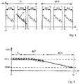
- Fig. 3 shows an example of measured values m(ti) measured by the measurement device 3 during a single performance of the batch process described above and a subsequently performed cleaning phase Pc.
- the measured values m(ti) are approximately constant during the empty phase Pe, during the reaction phase Pr and during the cleaning phase Pc. Further, they decrease during the first filling phase Pf1 and during the second filling phase Pf2 and increase during the discharging phase Pd.
- the predictive monitoring is performed based on the continuously recorded data D.
- the monitoring method requires for the operation of the facility to comprise the repeatedly occurring specific operation phase Ps, wherein measured values m(ti) measured during the specific operation phases Ps exhibit the characteristic C distinguishing the measured values m(ti) measured during the specific operation phases Ps from measured values measured m(ti) during other time periods, and wherein the characteristic C is compliant to the reference characteristic Cr, when the facility was operating properly and the measurement device 3 was compliant to the specified measurement accuracy during the respective specific operation phase Ps.
- the variable should either be equal to the same constant K or be given by the same deterministic function of time or be given by the same statistical pattern during each one of the repeated occurrences of the same operation phase.
- the measured values m(ti) measured during consecutive occurrences of the same operation phase should be the same within a tolerance accounting for variations due to the operation of the facility, the associated reproducibility of the trueness of the variable to the constant, the function or the pattern and variations accounting for the measurement properties and the limited measurement accuracy of the measurement device 3.
- operation of the facility comprises the repeatedly occurring specific operation phase Ps, wherein the measured values m(ti) measured during these specific operation phase Ps fulfill the requirement mentioned above, this automatically causes each characteristic C of measured values m(ti) measured during one of the specific operation phases Ps whilst the facility was operating properly and the measurement device 3 was compliant to the specified measurement accuracy to be compliant to reference characteristic Cr.
- the characteristic C is e.g. a characteristic including at least one property of the measured values m(ti), like e.g. their values, their slope, a value range in which they occur, their distribution and/or a pattern described by them during the specific operation phase Ps.
- the at least one property of the measured values m(ti) e.g. comprises at least one property corresponding to a model property of a model for the measured values m(ti) measured during the specific operation phase Ps.
- Suitable models include deterministic models, like e.g. physical models, for the deterministic behavior of the measured values m(ti), statistical models, like e.g.
- the reference characteristic Cr includes a reference property for each property included in the characteristic C, like e.g. a reference value, a reference slope, a reference value range, a refence pattern, a reference distribution, and/or a reference property for each of the model properties applied, representative of measured values m(ti) measured during one of the specific operation phases Ps whilst the facility was operating properly and the measurement device 3 was compliant to the specified measurement accuracy.
- measured values m(ti) measured during one of the specific operation phases Ps can be distinguished from measured values m(ti) measured during other time periods, based on a degree of compliancy of their characteristic C to the reference characteristic Cr.
- the method comprises a preliminary step of determining a classification method capable of identifying data sets S comprised in the data D, that have each been measured during one of the specific operation phases Ps.
- the classification method is determined based on training data comprised in the data D, that has been measured during a training time interval TI, during which the facility was operating properly and during which the measurement device 3 was compliant to the measurement accuracy specified for it.
- the training time interval TI is e.g. an interval following the installation of the measurement device 3.
- Compliancy to the specified measurement accuracy is e.g. ensured by requiring for the measurement device 3 to be installed to be a new device or a newly calibrated device compliant to the specified measurement accuracy.
- the determination of the classification method is e.g. performed by a calculating unit 29 embodied to determine the classification method based on the continuously recorded data D provided to it.
- the calculating unit 29 is e.g. trained to perform or designed to learn the determination of the classification method and to subsequently perform the classification method.
- the calculation unit 29 is e.g. embodied, e.g. trained or designed to learn, to determine classification criteria for identifying data sets S comprising measured values m(ti) measured during one of the specific operation phases Ps in the recorded data D based on the training data.
- Providing the data D to the calculating unit 29 is e.g. performed by transmitting the data D to a memory 31 associated to the calculating unit 29 and at least temporarily storing the data D in this memory 31.
- the measurement device 3 providing the measured values m(ti) and their time of measurement ti can e.g. be connected to and/or communicate with the calculation unit 29 directly, e.g. as illustrated by the arrow A, via the super-ordinated unit 27, e.g. as illustrate by the arrows B1 and B2, and/or via an edge device 33 located in the vicinity of the measurement device 3, e.g. as indicated by the arrows C1, C2.
- hard wired or wireless connections and/or communication protocols known in the art like e.g.
- the measurement device 3, the edge device 33 and/or the super-ordinated 27 can be directly or indirectly connected to the calculation unit 29 via the internet, e.g. via a communication network, like e.g. TCP/IP.
- a communication network like e.g. TCP/IP.
- the calculation unit 29 is e.g. embodied as a unit including hardware, like e.g. a computer or a computing system, located in the vicinity of the measurement device 3 or at a remote location.
- cloud computing can be applied.
- Cloud computing denominates an approach, wherein IT- infrastructure, like hardware, computing power, memory, network capacity and/or software are provided via a network, e.g. via the internet. In that case, the calculation unit 29 is embodied in the cloud.
- the classification method can be any method capable of identifying the data sets S in the continuously recorded data D. Determination of the classification method based on the training data is possible, due to the compliancy of the characteristic C exhibited by the measured values m(ti) measured during the specific operation phase Ps to the reference characteristic Cr during proper operation of the facility and of the measurement device 3. Thus, provided that the reference characteristic Cr is sufficiently distinct, the reference characteristic Cr is determinable and/or determined based on the training data. As an option, at least one of the models for the measured values m(ti) mentioned above and the corresponding at least one model property is determinable and/or determined based on the training data. In consequence, the characteristic C is determinable and/or determined based on the reference characteristic Cr and classification criteria enabling the identification of the data sets S are determinable and/or determined based on the training data without any prior knowledge about the characteristic C and the reference characteristic Cr.
- the classification criteria e.g. comprise at least one criterium concerning a value, a slope or a value range to be expected of measured values m(ti) measured during the specific operation phase Ps, at least one criterium concerning the distribution of the measured values m(ti) to be expected of measured values m(ti) measured during the specific operation phase Ps, at least one criterium concerning the pattern described by the measured values m(ti) to be expected of measured values m(ti) measured during the specific operation phase Ps, and/or at least one criterium concerning one of the model properties to be expected of measured values m(ti) measured during the specific operation phase Ps.
- the classification criteria e.g. comprise at least one criterium related to the degree of compliancy of at least one property of the measured values m(ti) included in the characteristic C to the corresponding reference property included in the reference characteristic Cr.
- the determination of the characteristic C, the determination of the reference characteristic Cr, the determination of the degree of compliancy of at least one or all properties of the characteristic C of the measured values m(ti) to the corresponding reference properties of the reference characteristic Cr, the determination of classification criteria and/or the identification of the data sets S comprised in the data D is e.g. determined by applying classification algorithms, like e.g. algorithm applied in support vector machines, in dynamic time warping or neural networks.
- the specific operation phase Ps is e.g. a repeatedly occurring operation phase that was predetermined based on information available on the operation of the facility.
- the specific operation phase Ps is identified based on the training data.
- the determination of the classification method e.g. includes the step of identifying the specific operation phase Ps.
- this information can be used to predetermine the specific operation phase Ps or to identify one or more potential candidates that might be suitable to be applied as the specific operation phase Ps and to identify the specific operation phase Ps based on these candidates.
- an operation phase wherein the variable should be equal to the same constant K during each occurrence of the respective operation phase can be predetermined to be the specific operation phase Ps or can be identified as one of the at least one potential candidates for the specific operation phase Ps.
- suitable candidates are e.g.
- the classification criteria e.g. include a criterium requiring for the measured values m(ti) to be stationary.
- the invention is however not limited to specific operation phases Ps, during which the variable should be constant.
- one of the at least one repeatedly occurring operation phases can be identified as the specific operation phase Ps and the characteristic C, the reference characteristic Cr and the classification method are e.g. determined by performing a method of supervised learning.
- identification of the specific operation phase Ps is e.g. performed without any prior knowledge about the repeatedly occurring operation phases and/or about potentially suitable candidates for the specific operation phase Ps.
- the specific operation phase Ps can even be an operation phase, the owner or user of the facility is unaware of. Regardless of whether candidates have been identified or not, the identification of the specific operation phase Ps and the determination of the classification method are e.g. both performed based on the training data comprised in the data D. This identification can be performed without any prior knowledge about the characteristic C and the reference characteristic Cr associated with the specific operation phase Ps.
- identification of the specific operation phase Ps is e.g. performed by identifying at least one group Gj of subsets of the training data, wherein each subset consists of data measured during a subset time interval and wherein subsets belonging to the same group Gj exhibit a degree of similarity that is larger or equal to a minimum degree of similarity required for the subsets to be considered to be belonging to the same group Gj.
- subsets comprised in the same group Gj can be considered to have been measured during the same operation phase and are thus representative of the respective operation phase.
- Determining subsets belonging to the same group Gj is e.g. performed by performing at least one of: an analysis of the values of the measured values m(ti), a correlation analysis, a pattern recognition method, an autocorrelation analysis, and another data analysis method capable of identifying subsets of sufficiently high similarity.
- a maximum of six different groups Gj of subsets, each corresponding to one of the six operation phases Pe, Pf1, Pf2, Pr, Pd, Pc can be determined.
- the subsets comprised in the respective group Gj that are representative of the same operation phase are identified as reference sets for the respective operation phase.
- this operation phase is determined to be the specific operation phase Ps and the characteristic C of the measured values m(ti) measured during this specific operation phase Ps, the reference characteristic Cr and classification criteria, like e.g. classification criteria including at least one of the criteria mentioned above, for identifying the data sets S are determined based on these reference sets.
- one of these operation phases is determined to be the specific operation phase Ps and the characteristic C, the reference characteristic Cr and the classification criteria for identifying the data sets S measured during specific operation phases Ps are determined as described above based on the reference sets for this specific operation phase Ps.
- one of the operation phases, for which reference sets have been determined can be arbitrarily selected to be the specific operation phase Ps.
- the selection is e.g. performed based on a frequency of occurrence and/or a duration of these operation phases.
- the selection is preferably performed based on a degree of similarity of the reference sets comprised in the same group Gj.
- Selecting an operation phase having a higher frequency of occurrence than at least one of the other operation phases, as well as selecting an operation phase having a longer duration than at least one of the other operation phases provides the advantage, that it increases the number and the rate of availability of measured values m(ti) measured during the specific operation phases Ps. Selecting an operation phase, for which reference sets exhibiting a higher degree of similarity have been determined improves the preciseness of the classification criteria and thus improves the capability of the classification method to identify the data sets S.
- each characteristic C determinable based on the measured values m(ti) comprised in one of the reference sets is compliant to the reference characteristic Cr.
- the reference characteristic Cr is determinable and/or determined based on the reference sets.
- classification criteria corresponding to the reference characteristic Cr are determinable and/or determined based on the reference sets.
- the calculation unit 29 is e.g. embodied to perform a process of machine learning. In this case the calculation unit 29 learns the classification method based on the training data and subsequently identifies the data sets S comprised in the data D by performing the learned method.
- the data sets S comprised in the data D are identified by performing this method.
- the classification method is e.g. performed by determining limited time intervals, wherein the measured values m(ti) measured during the respective time interval fulfill the classification criteria characteristic for the specific operation phase Ps and by identifying the fractions of the data D measured during these limited time intervals as the data sets S. Determining the measured values m(ti) measured during one of the limited time intervals and fulfilling the classification criteria is e.g. performed by performing at least one of: a correlation analysis, a pattern recognition method, an autocorrelation analysis, and/or another data analysis method capable of identifying the data sets S fulfilling the classification criteria.
- a time series ts of compliancy indicators I indicative of a degree of compliancy of at least one property of the characteristic C of the measured values m(ti) comprised in the respective data sets S to the corresponding reference property of the reference characteristic Cr is determined.
- This time series ts is continuously extended based on the data D continuously recorded during operation of the facility. Further, it is applied to at least once determine a remaining time RT remaining until the degree of compliancy indicated by compliancy indicators I to be determined based on measured values m(ti) measured during a future occurrence of the specific operation phase Ps will drop below a predetermined minimum degree of compliancy Imin. Determination of each remaining time RT is e.g. performed by performing a method of time series forecasting performed based on the compliancy indicators I comprised in the time series ts.
- Each remaining time RT is e.g. determined in form of a point in time t RT in the future at which the compliancy indicator I(t RT ) will drop below the minimum degree of compliancy Imin and/or in form of a remaining time interval RTI remaining until this point in time t RT .
- the determination of the time series ts is e.g. performed by the calculating unit 29 embodied to determine the time series ts based on the continuously recorded data D provided to it or based on the data sets S provided to it and the at least one property of the reference characteristic Cr determined by or provided to it.
- the calculating unit 29 is e.g. trained to perform or designed to learn and to perform the determination of the time series ts.
- the calculating 29 is e.g. embodied to determine the remaining time RT.
- the output is e.g. provided in form of an e-mail or a message automatically generated by the calculating unit 29 and dispatched to a predetermined recipient or a predetermined device, like e.g. the super-ordinated unit 27, a computer or a mobile device, like e.g. a cell phone, a tablet or a service tool.
- the method according to the invention provides the advantages mentioned above. Individual steps of the method can be implemented in different ways without deviating from the scope of the invention. Several optional embodiments are described in more detail below.
- the time series ts is e.g. determined by for each data set S identified by the classification method determining one of the compliancy indicators I of the time series ts.
- the time associated with each of the compliancy indicators I is e.g. a time stamp determined based on the time period during which the measured values m(ti) comprised in the respective data set S were measured, like e.g. a time stamp given by a starting time, an end time or a point in time in the middle of the time period.
- these compliancy indicators I are e.g. each determined to be equal to a quantitative measure of a degree of the similarity of the entire characteristic C exhibited by the measured values m(ti) included in the respective data set S and the entire reference characteristic Cr.
- This type of compliancy indicator I is especially suitable, when the reference characteristic Cr only comprises the reference pattern and/or the reference distribution described above.
- the compliancy indicators I are e.g. each determined based on a degree of similarity of the pattern described by the measured values m(ti) comprised in the respective data set S to the reference pattern and/or a degree of similarity of the distribution of the measured values m(ti) comprised in the respective data set S to the reference distribution.
- the compliancy indicators I are determined based on the degree of similarity of the respective entire characteristic C to the entire reference characteristic Cr they can e.g. be quantitatively determined in form of a percentage, wherein a target value of a degree of compliancy of 100% is achieved, in the ideal case, that characteristic C and reference characteristic are identical.
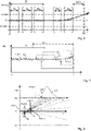
- Fig. 4 shows an example of sets of measured values m(ti) measured during the specific operation phase Ps.
- the first filling phase Pf1 repeatedly occurring in the example shown in Fig. 1 and 3 is applied as the specific operation phase Ps.
- Each set includes measured values m(ti) comprised in one of the data sets S, that have been measured during one of the occurrences of the first filling phase Pf1.
- the extract shown comprises three examples of sets of measured values m(ti), that have been measured during the training time interval TI and three examples of sets of measured values m(ti), that have been measured after the training time interval TI.
- the compliancy indicators I determined based on data sets S including measured values m(ti) measured after the training time interval TI decrease in time.
- a method of time series forecasting is e.g. applied to predict the remaining time RT remaining until the compliancy indicator I will drop below the minimum degree of compliancy Imin.
- the compliancy indicators I are e.g. determined based on the degree of compliancy of one or at least two of the properties of the characteristic C to the corresponding reference properties.
- This option is especially suitable, when the measured values m(ti) measured during the specific operation phase Ps can be described by a deterministic function f(t) of time t and a set of coefficients.
- This function f(t) of time t is e.g. determinable and/or determined based on the training data.
- the characteristic C e.g. comprises a set of fitted coefficients determined by fitting the measured values m(ti) to the function f(t) of time and the reference characteristic Cr comprises the corresponding reference coefficients.
- the degree of compliancy is e.g. quantitatively determined based on the deviations between the fitted coefficients and the reference coefficients.
- each compliancy indicator I determined for one of the data sets S is e.g. determined as a deviation between a slope of a straight line G fitted to the measured values m(ti) comprised in the data set S to the corresponding reference slope comprised in the reference characteristic Cr.
- the compliancy indicators I are e.g. each given by this property determined based on the respective data sets S.
- the time series ts is a time series ts of this property, like e.g. a time series of slopes.
- a target value for the degree of compliancy of 100% is achieved, when the properties are identical to the reference property and the compliancy indicators I drop below the minimum degree of compliancy, when the deviation between the property and the reference property exceeds a corresponding deviation range.
- the compliancy indicators I are e.g. each given by a quantitative measure of a deviation between the properties determined based on the respective data sets S and the reference properties.
- a target value of a degree of compliancy of 100% is achieved, in the ideal case, that the deviation is zero because all properties determined based on the respective data sets S are identical to the reference properties and the compliancy indicators I drop below the minimum degree of compliancy, when the compliancy indicators I given by theses deviations exceed a corresponding deviation range.
- the time series ts is a time series ts(m(ti)) of measured values m(ti) measured during the specific operation phases Ps.
- Fig. 6 shows an example of an extract of a time series ts of measured values m(ti), wherein each measured value m(ti) is included in one of the data sets S identified by the classification method and measured during one of the specific operation phases Ps. Because the measured the variable should be equal to the constant K during the specific operation phase Ps, the reference constant Kr for the measured values m(ti) comprised in the reference characteristic Cr corresponds to this constant K.
- the time series ts is e.g. determined by discarding all data elements comprised the data D apart from the measured values m(ti) comprised in the identified data sets S.
- this remaining time RT is e.g. given by the remaining time RT remaining until the measured values m(ti) to be measured during a future occurrences of the specific operation phase Ps will exceed the indicator value range ⁇ K.
- the measured values m(ti) measured after the training time interval TI increase in time and will thus exceed an upper limit Kr + ⁇ Kr of the value range ⁇ K.
- the reference constant Kr can be determined to be equal to the target value.
- the reference constant Kr is e.g. determined based on the measured values m(ti) comprised in the time series ts, that have been measured during the training time interval TI.
- the reference constant Kr is e.g. determined to be equal to an average or a mean value of the measured values m(ti) comprised in the time series ts, that have been measured during the training time interval TI.
- At least one of the remaining times RT is preferably determined by performing a method of time series forecasting.
- at least one of the remaining times RT is e.g. determined by performing a method of time series forecasting described in European Patent application No. 20168733.2 filed on April 8, 2020 , incorporated herein by reference.
- performance of this method comprises the method steps of:
- the deviation range DR is determined based on the minimum degree of compliancy Imin such, that the deviations d(ti) exceed the deviation range DR when the degree of compliancy indicated by the compliancy indicators I drops below the minimum degree of compliancy Imin.
- the compliancy indicators I are indicative of a degree of compliancy of a single property of the characteristic C to the corresponding reference properties and the time series ts is a time series ts of this property the deviations d(ti) determined in step a) are given by the deviation between the respective property and the reference property.
- the deviations d(ti) determined in step a) are given by the deviations d(ti) between the measured values m(ti) and the reference constant Kr.
- the remaining time RT is determined, by: for at least two different deviation pairs k, each comprising a first deviation d1 k (t1 k ) and a second deviation d2 k (t2 k ) determined based on the filtered deviations FD (t1 k ), FD (t2 k ) comprised in the monitoring time interval MTI determining a simulated value SRTk of the remaining time RT by performing a Monte Carlo simulation based on the noise and the respective deviation pair k.
- the deviation pairs k are e.g.
- the deviation pairs k are e.g. determined such, that the second deviation d2 k (t2 k ) of each pair k is given by the last filtered deviation FD(tn) or one of the last filtered deviation FD(ti) comprised in the monitoring time interval MTI.
- the random additives e 1 , e 2 are preferably generated according to a probability distribution reflecting the properties of the noise.
- a crossing time t x is determined as the time at which a straight line passing through the first random deviation E1(t1 k ) at the first time t1 k and through the second random deviation E2(t2 k ) at the second time t2 k will exceed the deviation range DR.
- Some examples of the thus determined straight lines are shown as dotted lines in Fig. 8 together with the deviation range DR, represented by the upper and the lower deviation limit - ⁇ Kr, + ⁇ Kr shown in Fig. 8 .
- a probability density function PDF(t x ) of the crossing times t x is determined and the simulated value SRT k is determined based on the probability density function PDF(t x ) of the crossing times t x .
- the remaining time RT is determined based on the simulated values SRT k determined for each deviation pair k, e.g. as an average or a weighted average of the simulated values SRT k .
- This method of time series forecasting has the advantage, that each simulated value SRTk accounts for an average rate of change of the deviations d(ti), that occurred in a time interval elapsed in-between the first and the second deviation d1 k (t1 k ), d2 k (t2 k ) of the respective deviation pair k.
- SRTk accounts for an average rate of change of the deviations d(ti), that occurred in a time interval elapsed in-between the first and the second deviation d1 k (t1 k ), d2 k (t2 k ) of the respective deviation pair k.
- the method neither requires for the measured values m(ti) comprised in the time series ts to be available at a fixed rate, nor to have been measured at consecutive previously known or predetermined points in time.
- the method can be further improved by following the determination of at least one remaining time RT determining at least one more remaining time RT as described above before the point in time t RT at which the degree of compliancy will drop below the minimum degree of compliancy according to the previously determined remaining time RT.
- the output informing about the remaining time RT is preferably updated accordingly every time a new remaining time RT has been determined.
- the method can be further improved by calibrating the measurement device 3 on or before the point in time t RT at which the compliancy indicators I will drop below the minimum degree of compliancy Imin according to the previously determined remaining time RT.
- a measurement error of the measurement device 3 determined. This measurement error is then compared to a predetermined threshold. In case the measurement error is larger than the threshold, impaired measurement properties of the measurement device 3 are determined as root cause causing the compliancy indicators I to drop below the minimum degree of compliancy Imin.
- the measurement device 3 is preferably adjusted, repaired or replaced and the method is restarted from the beginning by installing the thus obtained measurement device 3, which is compliant to the measurement accuracy specified for it.
- an impaired operation of the facility is determined as root cause, causing the compliancy indicators I to drop below the minimum degree of compliancy Imin.
- a fault causing the impaired operation is preferably determined and a corresponding remedy resolving the fault is preferably applied.
- the determination of the time series ts can be further refined by following the identification of the data sets S determining and discarding potentially polluted measured values m(ti) comprised in these data set S.
- the potentially polluted measured values m(ti) e.g. comprise edge values, measured at the beginning and/or at the end of the respective specific operation phase Ps. These edge values may be polluted due to side effects occurring at the transition from the previous operation phase to the respective specific operation phase Ps and at the transition from the respective specific operation phase Ps to the next operation phase. Determination and discarding of the potentially polluted measured values m(ti) is e.g. performed by the calculation unit 29 embodied, e.g.
- a machine learning method like e.g. a machine learning method for outlier detection or novelty detection, like e.g. Isolation Forest, Local Outlier Factor, Elliptic Envelope or One Class Support Vector Machine, can be applied.
- determining and discarding potentially polluted measured values m(ti) is preferably also applied during the determination of the classification method, e.g. by identifying and discarding potentially polluted measured values comprised to the subsets of the groups Gj determined based on the training data.
- the identification of the specific operation phase Ps, the determination of the characteristic C and/or the reference characteristic Cr, the determination of the classification method, the identification of the data sets S, the performance of the classification method, and/or the determination of the time series ts can be further improved by taking into account at least one parameter measured by the measurement device 3 during operation of the facility.
- the parameters e.g. comprise at least one parameter measured by a sensor of the measurement device 3, at least one parameter measured and applied by the measurement device 3 to determine the measured values m(ti) and/or to compensate a parameter-dependent measurement error of the measurement device 3.
- the parameters e.g. comprise a temperature measured by a temperature sensor 35 of the measurement device 3.
- the measurement device 3 is an electrochemical measurement device measuring a measuring a pH-value of the medium or a concentration of an analyte contained in the medium, like e.g. the pH-sensor shown in Fig. 2
- the parameters e.g. comprise a parameter given by the electrode potential Uel of the measuring electrode 15 extending into the measuring cell 9 and/or a parameter given by an electrical impedance Z of the membrane 11 closing off the measuring cell 9.
- the measurement electronics 17 of the measurement device 3 is e.g. embodied to determine the electrode potential Uel of the electrode 19 connected to the measurement electronics 17 and/or embodied to determine the membrane impedance Z.
- the membrane impedance Z is e.g.
- the membrane impedance Z is e.g. determined based on the dependency of the electrode potential Uel on the alternating voltage and the membrane impedance Z, occurring whilst the alternating voltage is applied to the reference electrode 23.
- the continuously recorded data D additionally comprises parameter values p(ti) of the parameter(s) measured by the measurement device 3 during operation of the facility and their time of measurement ti.
- the identification of the specific operation phase Ps, the determination of the classification method, the identification of the data sets S, the performance of the classification method, and the determination of the time series ts is performed as described above based on the measured values m(ti) and the measured parameter values p(ti) comprised in this data D.
- the classification criteria comprise at least one criterium concerning the measured values m(ti) and the measured parameter values p(ti) measured during the specific operation phases Pc. These classification criteria are e.g. determined based on reference sets determined as described above, each comprising the measured values m(ti) and the measured parameter values p(ti). These classification criteria e.g. comprise criteria concerning the values, the value range, the distribution of and/or the pattern described by the measured values m(ti) and/or the measured parameter values p(ti) measured during the specific operation phases Pc. Determining the time series ts additionally based on the measured parameter values p(ti) provides the advantage of a more precise and more reliable identification of the data sets S measured during the specific operation phases Ps.
- the measured parameter values p(ti) are e.g. applied with respect to the characteristic C, the reference characteristic Cr and the compliancy indicators I.
- the specific operation phase Ps is considered to be a specific operation phase Ps, wherein measured values m(ti) and measured parameter values p(ti) measured during the specific operation phases Ps exhibit the characteristic C distinguishing them from measured values m(ti) and measured parameter values p(ti) measured during other time periods.
- the characteristic C exhibited by the measured values m(ti) and the measured parameter values p(ti) is compliant to the corresponding reference characteristic Cr when the facility is operating properly and the measurement device 3 is compliant to the specified measurement accuracy.
- compliancy indicators I indicative of a degree of compliancy of at least one property of the characteristic C of the measured values m(ti) and the measured parameter values p(ti) comprised in the sets S to the corresponding reference property of the reference characteristic Cr can be applied in the same way as described above with respect to the compliancy indicators I indicative of the degree of compliancy of the at least one property of the characteristic C of the measured values m(ti).
- operation of the facility comprises two or more repeatedly occurring different operation phases, that are suitable to be applied as specific operation phase Ps.
- at least one additional remaining time RT' can be determined as described above based on at least one additional specific operation phase Ps', wherein measured values m(ti) measured during the additional specific operation phase Ps' exhibit a characteristic C' distinguishing these measured values m(ti) from measured values measured m(ti) during other time periods and wherein the characteristic C' is compliant to a reference characteristic Cr' when the facility is operating properly and the measurement device 3 is compliant to the specified measurement accuracy.
- the method comprises the additional steps of:
- Performing the method based on the specific operation phase Ps and at least one additional specific operation phase Ps' increases the number and the rate of availability at which measured values m(ti) based on which at least one of: the remaining time RT and the additional remaining time RT' can be determined. This is especially advantageous in application, wherein longer time gabs between consecutive occurrences of the specific operation phase Ps may occur.
Landscapes
- Physics & Mathematics (AREA)
- Chemical & Material Sciences (AREA)
- Life Sciences & Earth Sciences (AREA)
- General Physics & Mathematics (AREA)
- Health & Medical Sciences (AREA)
- Electrochemistry (AREA)
- Analytical Chemistry (AREA)
- Biochemistry (AREA)
- General Health & Medical Sciences (AREA)
- Immunology (AREA)
- Pathology (AREA)
- Chemical Kinetics & Catalysis (AREA)
- Molecular Biology (AREA)
- Engineering & Computer Science (AREA)
- Fluid Mechanics (AREA)
- Theoretical Computer Science (AREA)
- Computing Systems (AREA)
- Thermal Sciences (AREA)
- Automation & Control Theory (AREA)
- Bioinformatics & Cheminformatics (AREA)
- Bioinformatics & Computational Biology (AREA)
- Management, Administration, Business Operations System, And Electronic Commerce (AREA)
- Testing And Monitoring For Control Systems (AREA)
Applications Claiming Priority (1)
| Application Number | Priority Date | Filing Date | Title |
|---|---|---|---|
| DE102020130623 | 2020-11-19 |
Publications (2)
| Publication Number | Publication Date |
|---|---|
| EP4002041A1 true EP4002041A1 (fr) | 2022-05-25 |
| EP4002041B1 EP4002041B1 (fr) | 2023-04-12 |
Family
ID=77838688
Family Applications (1)
| Application Number | Title | Priority Date | Filing Date |
|---|---|---|---|
| EP21196403.6A Active EP4002041B1 (fr) | 2020-11-19 | 2021-09-13 | Procédé de surveillance prédictive d'une variable d'un milieu et d'une précision de mesure d'un dispositif de mesure de cette variable |
Country Status (3)
| Country | Link |
|---|---|
| US (1) | US11994488B2 (fr) |
| EP (1) | EP4002041B1 (fr) |
| CN (1) | CN114543932B (fr) |
Cited By (2)
| Publication number | Priority date | Publication date | Assignee | Title |
|---|---|---|---|---|
| DE102021130639A1 (de) | 2021-11-23 | 2023-05-25 | Endress+Hauser Conducta Gmbh+Co. Kg | Verfahren zum Bestimmen anwendungsspezifischer Gesamtplausibilitäten von Messwerten mindestens einer von einem Messsystem in einer spezifischen Anwendung gemessenen Messgröße |
| DE102022133822A1 (de) * | 2022-12-19 | 2024-06-20 | Endress+Hauser Conducta Gmbh+Co. Kg | Verfahren zum Messen von Messgrößen eines Mediums und Messsystem, das konfiguriert ist, um dieses Verfahren durchzuführen |
Citations (3)
| Publication number | Priority date | Publication date | Assignee | Title |
|---|---|---|---|---|
| EP2602680B1 (fr) | 2011-12-09 | 2014-06-18 | Endress + Hauser Messtechnik GmbH+Co. KG | Procédé pour déterminer un intervalle de temps d'étalonnage pour l'étalonnage d'un dispositif de mesure |
| DE102018109696A1 (de) | 2018-04-23 | 2019-10-24 | Endress+Hauser Conducta Gmbh+Co. Kg | Vorrichtung und Verfahren zur Verifizierung, Kalibrierung und/oder Justierung eines Inline-Messgeräts |
| EP3739403A1 (fr) * | 2019-05-15 | 2020-11-18 | Endress+Hauser Group Services AG | Procédé de fonctionnement et de surveillance prédictive d'un dispositif de terrain |
Family Cites Families (9)
| Publication number | Priority date | Publication date | Assignee | Title |
|---|---|---|---|---|
| DE102004063468A1 (de) * | 2004-12-23 | 2006-07-06 | Endress + Hauser Conducta Gesellschaft für Mess- und Regeltechnik mbH + Co. KG | Verfahren zur Funktionsüberwachung eines Sensors |
| DE102012108739A1 (de) * | 2012-09-18 | 2014-03-20 | Endress + Hauser Conducta Gesellschaft für Mess- und Regeltechnik mbH + Co. KG | Verfahren und Vorrichtung zur Bestimmung eines Zustands einer Messsonde |
| DE102016117733A1 (de) * | 2015-10-09 | 2017-04-13 | Endress+Hauser Conducta Gmbh+Co. Kg | Messeinrichtung |
| KR102215690B1 (ko) * | 2015-12-29 | 2021-02-16 | 삼성에스디에스 주식회사 | 시계열의 데이터를 모니터링 하는 방법 및 그 장치 |
| ES2772751T3 (es) * | 2017-03-07 | 2020-07-08 | Hoffmann La Roche | Procedimiento para determinar una concentración de analito |
| KR101843879B1 (ko) * | 2017-06-26 | 2018-03-30 | 한국환경공단 | 이상 자료 검출 시스템, 이를 위한 방법 및 이 방법이 기록된 컴퓨터로 판독 가능한 기록 매체 |
| DE102018217166A1 (de) | 2018-10-08 | 2019-09-26 | Siemens Aktiengesellschaft | Messung von physikalischen Größen eines Stoffs |
| DE102018125908A1 (de) * | 2018-10-18 | 2020-04-23 | Endress+Hauser Conducta Gmbh+Co. Kg | Verfahren zur Bestimmung einer Prozessgrößer mit einem Klassifikator zur Auswahl eines Messverfahrens |
| EP3671385B1 (fr) * | 2018-12-20 | 2023-08-09 | Endress+Hauser Group Services AG | Procédé de détermination de l'intervalle de temps jusqu'à ce qu'une intervention d'entretien soit nécessaire |
-
2021
- 2021-09-13 EP EP21196403.6A patent/EP4002041B1/fr active Active
- 2021-10-14 CN CN202111196446.2A patent/CN114543932B/zh active Active
- 2021-11-18 US US17/530,049 patent/US11994488B2/en active Active
Patent Citations (3)
| Publication number | Priority date | Publication date | Assignee | Title |
|---|---|---|---|---|
| EP2602680B1 (fr) | 2011-12-09 | 2014-06-18 | Endress + Hauser Messtechnik GmbH+Co. KG | Procédé pour déterminer un intervalle de temps d'étalonnage pour l'étalonnage d'un dispositif de mesure |
| DE102018109696A1 (de) | 2018-04-23 | 2019-10-24 | Endress+Hauser Conducta Gmbh+Co. Kg | Vorrichtung und Verfahren zur Verifizierung, Kalibrierung und/oder Justierung eines Inline-Messgeräts |
| EP3739403A1 (fr) * | 2019-05-15 | 2020-11-18 | Endress+Hauser Group Services AG | Procédé de fonctionnement et de surveillance prédictive d'un dispositif de terrain |
Cited By (2)
| Publication number | Priority date | Publication date | Assignee | Title |
|---|---|---|---|---|
| DE102021130639A1 (de) | 2021-11-23 | 2023-05-25 | Endress+Hauser Conducta Gmbh+Co. Kg | Verfahren zum Bestimmen anwendungsspezifischer Gesamtplausibilitäten von Messwerten mindestens einer von einem Messsystem in einer spezifischen Anwendung gemessenen Messgröße |
| DE102022133822A1 (de) * | 2022-12-19 | 2024-06-20 | Endress+Hauser Conducta Gmbh+Co. Kg | Verfahren zum Messen von Messgrößen eines Mediums und Messsystem, das konfiguriert ist, um dieses Verfahren durchzuführen |
Also Published As
| Publication number | Publication date |
|---|---|
| EP4002041B1 (fr) | 2023-04-12 |
| US20220155252A1 (en) | 2022-05-19 |
| CN114543932B (zh) | 2025-07-15 |
| US11994488B2 (en) | 2024-05-28 |
| CN114543932A (zh) | 2022-05-27 |
Similar Documents
| Publication | Publication Date | Title |
|---|---|---|
| CN102144158B (zh) | 用于操作测量站的方法和测量站 | |
| JP5771527B2 (ja) | 原油装置における腐食および腐食副産物堆積を低減させる方法 | |
| US8005629B2 (en) | Method for monitoring sensor function | |
| EP4002041B1 (fr) | Procédé de surveillance prédictive d'une variable d'un milieu et d'une précision de mesure d'un dispositif de mesure de cette variable | |
| EP2602680B1 (fr) | Procédé pour déterminer un intervalle de temps d'étalonnage pour l'étalonnage d'un dispositif de mesure | |
| CN104870991B (zh) | 用于确定集成在过程容器中的测量变换器的状态的方法和设备 | |
| US11435212B2 (en) | Method of operating and of predictive monitoring of a field device | |
| WO1999027466A2 (fr) | Systeme et procede permettant de realiser un controle de la qualite intelligent d'un processus | |
| JP2019090024A (ja) | 石油精製所における腐食を低減する方法 | |
| CN111751508A (zh) | 一种水质传感器生命周期的性能评估预测方法及系统 | |
| US20160018372A1 (en) | Method for operating a measuring site | |
| EP4401015A1 (fr) | Système de mesure, procédé de détermination d'anomalie de système de mesure et programme de détermination d'anomalie de système de mesure | |
| DE102008045840A1 (de) | Verfahren zum Betreiben einer Prozess-Messstelle | |
| US20230161679A1 (en) | Method of determining application-specific total plausibilities of measured values of at least one measurand measured by a measurement system in a specific application | |
| Feital et al. | Use of variance spectra for in‐line validation of process measurements in continuous processes | |
| CN115183805B (zh) | 基于人工智能的仪器自动化计量检定方法及系统 | |
| CN112613632A (zh) | 功率预测模型建立方法、预测方法、装置及电子设备 | |
| US20240200990A1 (en) | Method of measuring measurands of a medium and a measurement system configured to perform this method | |
| EP4118499B1 (fr) | Adaptation du taux d'inspection | |
| Cundeva-Blajer | Data Science for Testing, Inspection and Certification | |
| CN114545107A (zh) | 用测量仪器监视过程设备中测量的被测变量的方法 | |
| US20250174115A1 (en) | Field device and system comprising the field device | |
| Wärff | Operational digital twins for water resource recovery facilities–Rationale, components, and case studies | |
| CN117191104A (zh) | 化学仪表自动标定方法及装置 | |
| CN121612778A (zh) | 一种多因素耦合的合金腐蚀行为的试验装置及方法 |
Legal Events
| Date | Code | Title | Description |
|---|---|---|---|
| PUAI | Public reference made under article 153(3) epc to a published international application that has entered the european phase |
Free format text: ORIGINAL CODE: 0009012 |
|
| STAA | Information on the status of an ep patent application or granted ep patent |
Free format text: STATUS: THE APPLICATION HAS BEEN PUBLISHED |
|
| AK | Designated contracting states |
Kind code of ref document: A1 Designated state(s): AL AT BE BG CH CY CZ DE DK EE ES FI FR GB GR HR HU IE IS IT LI LT LU LV MC MK MT NL NO PL PT RO RS SE SI SK SM TR |
|
| STAA | Information on the status of an ep patent application or granted ep patent |
Free format text: STATUS: REQUEST FOR EXAMINATION WAS MADE |
|
| 17P | Request for examination filed |
Effective date: 20220711 |
|
| RBV | Designated contracting states (corrected) |
Designated state(s): AL AT BE BG CH CY CZ DE DK EE ES FI FR GB GR HR HU IE IS IT LI LT LU LV MC MK MT NL NO PL PT RO RS SE SI SK SM TR |
|
| GRAP | Despatch of communication of intention to grant a patent |
Free format text: ORIGINAL CODE: EPIDOSNIGR1 |
|
| STAA | Information on the status of an ep patent application or granted ep patent |
Free format text: STATUS: GRANT OF PATENT IS INTENDED |
|
| INTG | Intention to grant announced |
Effective date: 20221209 |
|
| GRAS | Grant fee paid |
Free format text: ORIGINAL CODE: EPIDOSNIGR3 |
|
| GRAA | (expected) grant |
Free format text: ORIGINAL CODE: 0009210 |
|
| STAA | Information on the status of an ep patent application or granted ep patent |
Free format text: STATUS: THE PATENT HAS BEEN GRANTED |
|
| AK | Designated contracting states |
Kind code of ref document: B1 Designated state(s): AL AT BE BG CH CY CZ DE DK EE ES FI FR GB GR HR HU IE IS IT LI LT LU LV MC MK MT NL NO PL PT RO RS SE SI SK SM TR |
|
| REG | Reference to a national code |
Ref country code: GB Ref legal event code: FG4D |
|
| REG | Reference to a national code |
Ref country code: CH Ref legal event code: EP |
|
| REG | Reference to a national code |
Ref country code: DE Ref legal event code: R096 Ref document number: 602021001883 Country of ref document: DE |
|
| REG | Reference to a national code |
Ref country code: IE Ref legal event code: FG4D |
|
| REG | Reference to a national code |
Ref country code: AT Ref legal event code: REF Ref document number: 1560136 Country of ref document: AT Kind code of ref document: T Effective date: 20230515 |
|
| P01 | Opt-out of the competence of the unified patent court (upc) registered |
Effective date: 20230601 |
|
| REG | Reference to a national code |
Ref country code: NL Ref legal event code: FP |
|
| REG | Reference to a national code |
Ref country code: LT Ref legal event code: MG9D |
|
| REG | Reference to a national code |
Ref country code: AT Ref legal event code: MK05 Ref document number: 1560136 Country of ref document: AT Kind code of ref document: T Effective date: 20230412 |
|
| PG25 | Lapsed in a contracting state [announced via postgrant information from national office to epo] |
Ref country code: SE Free format text: LAPSE BECAUSE OF FAILURE TO SUBMIT A TRANSLATION OF THE DESCRIPTION OR TO PAY THE FEE WITHIN THE PRESCRIBED TIME-LIMIT Effective date: 20230412 Ref country code: PT Free format text: LAPSE BECAUSE OF FAILURE TO SUBMIT A TRANSLATION OF THE DESCRIPTION OR TO PAY THE FEE WITHIN THE PRESCRIBED TIME-LIMIT Effective date: 20230814 Ref country code: NO Free format text: LAPSE BECAUSE OF FAILURE TO SUBMIT A TRANSLATION OF THE DESCRIPTION OR TO PAY THE FEE WITHIN THE PRESCRIBED TIME-LIMIT Effective date: 20230712 Ref country code: ES Free format text: LAPSE BECAUSE OF FAILURE TO SUBMIT A TRANSLATION OF THE DESCRIPTION OR TO PAY THE FEE WITHIN THE PRESCRIBED TIME-LIMIT Effective date: 20230412 Ref country code: AT Free format text: LAPSE BECAUSE OF FAILURE TO SUBMIT A TRANSLATION OF THE DESCRIPTION OR TO PAY THE FEE WITHIN THE PRESCRIBED TIME-LIMIT Effective date: 20230412 |
|
| PG25 | Lapsed in a contracting state [announced via postgrant information from national office to epo] |
Ref country code: RS Free format text: LAPSE BECAUSE OF FAILURE TO SUBMIT A TRANSLATION OF THE DESCRIPTION OR TO PAY THE FEE WITHIN THE PRESCRIBED TIME-LIMIT Effective date: 20230412 Ref country code: PL Free format text: LAPSE BECAUSE OF FAILURE TO SUBMIT A TRANSLATION OF THE DESCRIPTION OR TO PAY THE FEE WITHIN THE PRESCRIBED TIME-LIMIT Effective date: 20230412 Ref country code: LV Free format text: LAPSE BECAUSE OF FAILURE TO SUBMIT A TRANSLATION OF THE DESCRIPTION OR TO PAY THE FEE WITHIN THE PRESCRIBED TIME-LIMIT Effective date: 20230412 Ref country code: LT Free format text: LAPSE BECAUSE OF FAILURE TO SUBMIT A TRANSLATION OF THE DESCRIPTION OR TO PAY THE FEE WITHIN THE PRESCRIBED TIME-LIMIT Effective date: 20230412 Ref country code: IS Free format text: LAPSE BECAUSE OF FAILURE TO SUBMIT A TRANSLATION OF THE DESCRIPTION OR TO PAY THE FEE WITHIN THE PRESCRIBED TIME-LIMIT Effective date: 20230812 Ref country code: HR Free format text: LAPSE BECAUSE OF FAILURE TO SUBMIT A TRANSLATION OF THE DESCRIPTION OR TO PAY THE FEE WITHIN THE PRESCRIBED TIME-LIMIT Effective date: 20230412 Ref country code: GR Free format text: LAPSE BECAUSE OF FAILURE TO SUBMIT A TRANSLATION OF THE DESCRIPTION OR TO PAY THE FEE WITHIN THE PRESCRIBED TIME-LIMIT Effective date: 20230713 |
|
| PG25 | Lapsed in a contracting state [announced via postgrant information from national office to epo] |
Ref country code: FI Free format text: LAPSE BECAUSE OF FAILURE TO SUBMIT A TRANSLATION OF THE DESCRIPTION OR TO PAY THE FEE WITHIN THE PRESCRIBED TIME-LIMIT Effective date: 20230412 |
|
| REG | Reference to a national code |
Ref country code: DE Ref legal event code: R097 Ref document number: 602021001883 Country of ref document: DE |
|
| PG25 | Lapsed in a contracting state [announced via postgrant information from national office to epo] |
Ref country code: SK Free format text: LAPSE BECAUSE OF FAILURE TO SUBMIT A TRANSLATION OF THE DESCRIPTION OR TO PAY THE FEE WITHIN THE PRESCRIBED TIME-LIMIT Effective date: 20230412 |
|
| PG25 | Lapsed in a contracting state [announced via postgrant information from national office to epo] |
Ref country code: SM Free format text: LAPSE BECAUSE OF FAILURE TO SUBMIT A TRANSLATION OF THE DESCRIPTION OR TO PAY THE FEE WITHIN THE PRESCRIBED TIME-LIMIT Effective date: 20230412 Ref country code: SK Free format text: LAPSE BECAUSE OF FAILURE TO SUBMIT A TRANSLATION OF THE DESCRIPTION OR TO PAY THE FEE WITHIN THE PRESCRIBED TIME-LIMIT Effective date: 20230412 Ref country code: RO Free format text: LAPSE BECAUSE OF FAILURE TO SUBMIT A TRANSLATION OF THE DESCRIPTION OR TO PAY THE FEE WITHIN THE PRESCRIBED TIME-LIMIT Effective date: 20230412 Ref country code: EE Free format text: LAPSE BECAUSE OF FAILURE TO SUBMIT A TRANSLATION OF THE DESCRIPTION OR TO PAY THE FEE WITHIN THE PRESCRIBED TIME-LIMIT Effective date: 20230412 Ref country code: DK Free format text: LAPSE BECAUSE OF FAILURE TO SUBMIT A TRANSLATION OF THE DESCRIPTION OR TO PAY THE FEE WITHIN THE PRESCRIBED TIME-LIMIT Effective date: 20230412 Ref country code: CZ Free format text: LAPSE BECAUSE OF FAILURE TO SUBMIT A TRANSLATION OF THE DESCRIPTION OR TO PAY THE FEE WITHIN THE PRESCRIBED TIME-LIMIT Effective date: 20230412 |
|
| PLBE | No opposition filed within time limit |
Free format text: ORIGINAL CODE: 0009261 |
|
| STAA | Information on the status of an ep patent application or granted ep patent |
Free format text: STATUS: NO OPPOSITION FILED WITHIN TIME LIMIT |
|
| 26N | No opposition filed |
Effective date: 20240115 |
|
| PG25 | Lapsed in a contracting state [announced via postgrant information from national office to epo] |
Ref country code: SI Free format text: LAPSE BECAUSE OF FAILURE TO SUBMIT A TRANSLATION OF THE DESCRIPTION OR TO PAY THE FEE WITHIN THE PRESCRIBED TIME-LIMIT Effective date: 20230412 |
|
| PG25 | Lapsed in a contracting state [announced via postgrant information from national office to epo] |
Ref country code: LU Free format text: LAPSE BECAUSE OF NON-PAYMENT OF DUE FEES Effective date: 20230913 |
|
| REG | Reference to a national code |
Ref country code: BE Ref legal event code: MM Effective date: 20230930 |
|
| PG25 | Lapsed in a contracting state [announced via postgrant information from national office to epo] |
Ref country code: SI Free format text: LAPSE BECAUSE OF FAILURE TO SUBMIT A TRANSLATION OF THE DESCRIPTION OR TO PAY THE FEE WITHIN THE PRESCRIBED TIME-LIMIT Effective date: 20230412 Ref country code: LU Free format text: LAPSE BECAUSE OF NON-PAYMENT OF DUE FEES Effective date: 20230913 Ref country code: IT Free format text: LAPSE BECAUSE OF FAILURE TO SUBMIT A TRANSLATION OF THE DESCRIPTION OR TO PAY THE FEE WITHIN THE PRESCRIBED TIME-LIMIT Effective date: 20230412 Ref country code: MC Free format text: LAPSE BECAUSE OF FAILURE TO SUBMIT A TRANSLATION OF THE DESCRIPTION OR TO PAY THE FEE WITHIN THE PRESCRIBED TIME-LIMIT Effective date: 20230412 |
|
| REG | Reference to a national code |
Ref country code: IE Ref legal event code: MM4A |
|
| PG25 | Lapsed in a contracting state [announced via postgrant information from national office to epo] |
Ref country code: IE Free format text: LAPSE BECAUSE OF NON-PAYMENT OF DUE FEES Effective date: 20230913 |
|
| PG25 | Lapsed in a contracting state [announced via postgrant information from national office to epo] |
Ref country code: IE Free format text: LAPSE BECAUSE OF NON-PAYMENT OF DUE FEES Effective date: 20230913 |
|
| PG25 | Lapsed in a contracting state [announced via postgrant information from national office to epo] |
Ref country code: BE Free format text: LAPSE BECAUSE OF NON-PAYMENT OF DUE FEES Effective date: 20230930 |
|
| PG25 | Lapsed in a contracting state [announced via postgrant information from national office to epo] |
Ref country code: BG Free format text: LAPSE BECAUSE OF FAILURE TO SUBMIT A TRANSLATION OF THE DESCRIPTION OR TO PAY THE FEE WITHIN THE PRESCRIBED TIME-LIMIT Effective date: 20230412 |
|
| PG25 | Lapsed in a contracting state [announced via postgrant information from national office to epo] |
Ref country code: BG Free format text: LAPSE BECAUSE OF FAILURE TO SUBMIT A TRANSLATION OF THE DESCRIPTION OR TO PAY THE FEE WITHIN THE PRESCRIBED TIME-LIMIT Effective date: 20230412 |
|
| PG25 | Lapsed in a contracting state [announced via postgrant information from national office to epo] |
Ref country code: CY Free format text: LAPSE BECAUSE OF FAILURE TO SUBMIT A TRANSLATION OF THE DESCRIPTION OR TO PAY THE FEE WITHIN THE PRESCRIBED TIME-LIMIT; INVALID AB INITIO Effective date: 20210913 |
|
| PG25 | Lapsed in a contracting state [announced via postgrant information from national office to epo] |
Ref country code: HU Free format text: LAPSE BECAUSE OF FAILURE TO SUBMIT A TRANSLATION OF THE DESCRIPTION OR TO PAY THE FEE WITHIN THE PRESCRIBED TIME-LIMIT; INVALID AB INITIO Effective date: 20210913 |
|
| REG | Reference to a national code |
Ref country code: CH Ref legal event code: U11 Free format text: ST27 STATUS EVENT CODE: U-0-0-U10-U11 (AS PROVIDED BY THE NATIONAL OFFICE) Effective date: 20251001 |
|
| PGFP | Annual fee paid to national office [announced via postgrant information from national office to epo] |
Ref country code: DE Payment date: 20250919 Year of fee payment: 5 |
|
| PGFP | Annual fee paid to national office [announced via postgrant information from national office to epo] |
Ref country code: NL Payment date: 20250918 Year of fee payment: 5 |
|
| PGFP | Annual fee paid to national office [announced via postgrant information from national office to epo] |
Ref country code: GB Payment date: 20250919 Year of fee payment: 5 |
|
| PGFP | Annual fee paid to national office [announced via postgrant information from national office to epo] |
Ref country code: FR Payment date: 20250922 Year of fee payment: 5 |
|
| PG25 | Lapsed in a contracting state [announced via postgrant information from national office to epo] |
Ref country code: TR Free format text: LAPSE BECAUSE OF FAILURE TO SUBMIT A TRANSLATION OF THE DESCRIPTION OR TO PAY THE FEE WITHIN THE PRESCRIBED TIME-LIMIT Effective date: 20230412 |
|
| PGFP | Annual fee paid to national office [announced via postgrant information from national office to epo] |
Ref country code: CH Payment date: 20251001 Year of fee payment: 5 |