EP4002063A1 - Bildanzeigevorrichtung und verfahren zur bewegungsdetektion einer bildanzeigevorrichtung - Google Patents
Bildanzeigevorrichtung und verfahren zur bewegungsdetektion einer bildanzeigevorrichtung Download PDFInfo
- Publication number
- EP4002063A1 EP4002063A1 EP19938654.1A EP19938654A EP4002063A1 EP 4002063 A1 EP4002063 A1 EP 4002063A1 EP 19938654 A EP19938654 A EP 19938654A EP 4002063 A1 EP4002063 A1 EP 4002063A1
- Authority
- EP
- European Patent Office
- Prior art keywords
- motion
- image
- user
- blocks
- display device
- Prior art date
- Legal status (The legal status is an assumption and is not a legal conclusion. Google has not performed a legal analysis and makes no representation as to the accuracy of the status listed.)
- Pending
Links
Images





Classifications
-
- G—PHYSICS
- G09—EDUCATION; CRYPTOGRAPHY; DISPLAY; ADVERTISING; SEALS
- G09G—ARRANGEMENTS OR CIRCUITS FOR CONTROL OF INDICATING DEVICES USING STATIC MEANS TO PRESENT VARIABLE INFORMATION
- G09G3/00—Control arrangements or circuits, of interest only in connection with visual indicators other than cathode-ray tubes
- G09G3/03—Control arrangements or circuits, of interest only in connection with visual indicators other than cathode-ray tubes specially adapted for displays having non-planar surfaces, e.g. curved displays
- G09G3/035—Control arrangements or circuits, of interest only in connection with visual indicators other than cathode-ray tubes specially adapted for displays having non-planar surfaces, e.g. curved displays for flexible display surfaces
-
- G—PHYSICS
- G06—COMPUTING OR CALCULATING; COUNTING
- G06T—IMAGE DATA PROCESSING OR GENERATION, IN GENERAL
- G06T7/00—Image analysis
- G06T7/20—Analysis of motion
- G06T7/246—Analysis of motion using feature-based methods, e.g. the tracking of corners or segments
- G06T7/248—Analysis of motion using feature-based methods, e.g. the tracking of corners or segments involving reference images or patches
-
- G—PHYSICS
- G06—COMPUTING OR CALCULATING; COUNTING
- G06T—IMAGE DATA PROCESSING OR GENERATION, IN GENERAL
- G06T7/00—Image analysis
- G06T7/20—Analysis of motion
- G06T7/254—Analysis of motion involving subtraction of images
-
- G—PHYSICS
- G09—EDUCATION; CRYPTOGRAPHY; DISPLAY; ADVERTISING; SEALS
- G09G—ARRANGEMENTS OR CIRCUITS FOR CONTROL OF INDICATING DEVICES USING STATIC MEANS TO PRESENT VARIABLE INFORMATION
- G09G5/00—Control arrangements or circuits for visual indicators common to cathode-ray tube indicators and other visual indicators
- G09G5/003—Details of a display terminal, the details relating to the control arrangement of the display terminal and to the interfaces thereto
-
- G—PHYSICS
- G06—COMPUTING OR CALCULATING; COUNTING
- G06T—IMAGE DATA PROCESSING OR GENERATION, IN GENERAL
- G06T2207/00—Indexing scheme for image analysis or image enhancement
- G06T2207/20—Special algorithmic details
- G06T2207/20021—Dividing image into blocks, subimages or windows
-
- G—PHYSICS
- G06—COMPUTING OR CALCULATING; COUNTING
- G06T—IMAGE DATA PROCESSING OR GENERATION, IN GENERAL
- G06T2207/00—Indexing scheme for image analysis or image enhancement
- G06T2207/20—Special algorithmic details
- G06T2207/20212—Image combination
- G06T2207/20224—Image subtraction
-
- G—PHYSICS
- G09—EDUCATION; CRYPTOGRAPHY; DISPLAY; ADVERTISING; SEALS
- G09G—ARRANGEMENTS OR CIRCUITS FOR CONTROL OF INDICATING DEVICES USING STATIC MEANS TO PRESENT VARIABLE INFORMATION
- G09G2320/00—Control of display operating conditions
- G09G2320/10—Special adaptations of display systems for operation with variable images
- G09G2320/103—Detection of image changes, e.g. determination of an index representative of the image change
-
- G—PHYSICS
- G09—EDUCATION; CRYPTOGRAPHY; DISPLAY; ADVERTISING; SEALS
- G09G—ARRANGEMENTS OR CIRCUITS FOR CONTROL OF INDICATING DEVICES USING STATIC MEANS TO PRESENT VARIABLE INFORMATION
- G09G2320/00—Control of display operating conditions
- G09G2320/10—Special adaptations of display systems for operation with variable images
- G09G2320/106—Determination of movement vectors or equivalent parameters within the image
-
- G—PHYSICS
- G09—EDUCATION; CRYPTOGRAPHY; DISPLAY; ADVERTISING; SEALS
- G09G—ARRANGEMENTS OR CIRCUITS FOR CONTROL OF INDICATING DEVICES USING STATIC MEANS TO PRESENT VARIABLE INFORMATION
- G09G2330/00—Aspects of power supply; Aspects of display protection and defect management
- G09G2330/02—Details of power systems and of start or stop of display operation
- G09G2330/021—Power management, e.g. power saving
-
- G—PHYSICS
- G09—EDUCATION; CRYPTOGRAPHY; DISPLAY; ADVERTISING; SEALS
- G09G—ARRANGEMENTS OR CIRCUITS FOR CONTROL OF INDICATING DEVICES USING STATIC MEANS TO PRESENT VARIABLE INFORMATION
- G09G2330/00—Aspects of power supply; Aspects of display protection and defect management
- G09G2330/02—Details of power systems and of start or stop of display operation
- G09G2330/021—Power management, e.g. power saving
- G09G2330/022—Power management, e.g. power saving in absence of operation, e.g. no data being entered during a predetermined time
-
- G—PHYSICS
- G09—EDUCATION; CRYPTOGRAPHY; DISPLAY; ADVERTISING; SEALS
- G09G—ARRANGEMENTS OR CIRCUITS FOR CONTROL OF INDICATING DEVICES USING STATIC MEANS TO PRESENT VARIABLE INFORMATION
- G09G2354/00—Aspects of interface with display user
-
- G—PHYSICS
- G09—EDUCATION; CRYPTOGRAPHY; DISPLAY; ADVERTISING; SEALS
- G09G—ARRANGEMENTS OR CIRCUITS FOR CONTROL OF INDICATING DEVICES USING STATIC MEANS TO PRESENT VARIABLE INFORMATION
- G09G2360/00—Aspects of the architecture of display systems
- G09G2360/14—Detecting light within display terminals, e.g. using a single or a plurality of photosensors
- G09G2360/144—Detecting light within display terminals, e.g. using a single or a plurality of photosensors the light being ambient light
-
- G—PHYSICS
- G09—EDUCATION; CRYPTOGRAPHY; DISPLAY; ADVERTISING; SEALS
- G09G—ARRANGEMENTS OR CIRCUITS FOR CONTROL OF INDICATING DEVICES USING STATIC MEANS TO PRESENT VARIABLE INFORMATION
- G09G2380/00—Specific applications
- G09G2380/02—Flexible displays
Definitions
- the present invention relates to an image display device and a motion detection method of the image display device. More particularly, the present invention relates to an image display device having a motion detection function and to a motion detection method of the image display device.
- an image display device displays an image on a display module, such as a cathode ray tube, a liquid crystal panel, an electroluminescent panel, a light emitting diode panel, a plasma display panel, and the like.
- a display module such as a cathode ray tube, a liquid crystal panel, an electroluminescent panel, a light emitting diode panel, a plasma display panel, and the like.
- an image display device is equipped with a camera module to detect a motion of a user in front of the image display device.
- the image display device switches to a power saving mode when there is no user motion detected.
- the conventional technique has a problem in that a sudden change in ambient illuminance or a movement of a periodically moving object is erroneously detected as a motion of a user, resulting in an unexpected activation of the image display device.
- An obj ective of the present invention is to provide an image display device that detects a motion of a user and outputs at least one of light (i.e., visual signal) and sound (i.e., audio signal) as welcome feedback.
- Another objective of the present invention is to provide an image display device capable of detecting a motion of a user and switching a display panel from a partial view state to a zero view state.
- a further objective of the present invention is to provide a motion detection method for an image display device, the method being capable of preventing a sudden change in illuminance or a movement of a periodically moving object which is not a human being from being recognized as a motion of a user, thereby preventing erroneous detection of a user motion, which contributes to power saving.
- an image display device equipped with a motion detection unit for detecting a motion of a user.
- a motion detection unit for detecting a motion of a user.
- alight emitting unit and/or an audio output unit is controlled to output light and/or sound as their welcome feedback signal.
- an image display device equipped with a motion detection unit for detecting a motion of a user.
- a motion detection unit for detecting a motion of a user.
- a motion detection method of an image display device includes a motion exclusion process of determining whether it is a motion exclusion condition on the basis of an overall change, a local change, or both in pixel brightness value between two temporally adjacent frames each being composed of a plurality of blocks, thereby preventing erroneous detection in detecting a motion of a user.
- the image display device can draw user's attention by outputting light, sound, or both as welcome feedback after detecting a user motion.
- the image display device can save power and maximize space utilization by detecting a motion of a user and switching a display panel from a partial view state to a zero view state when no user motion is detected.
- the motion detection method of the image display device can prevent erroneous user motion detection by preventing a sudden change in illuminance or a movement of a periodically moving object from being recognized as a user motion.
- FIGS. 1 and 2 are schematic views illustrating an image display device 100 according to one exemplary embodiment of the present invention
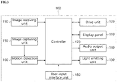
- FIG. 3 is a block diagram of the image display device 100 according to one exemplary embodiment of the present invention.
- the image display device 100 includes a rollable display panel 110, a drive unit 120, a housing 101, a motion detection unit 160, and a controller 170.
- the display panel 110 is a flexible display panel 110 that is variable in size. That is, the display panel 110 may be accommodated in the housing 101 when it is fully rolled down and may be stretched out of the housing when rolled up.
- the display panel 110 is, for example, an organic light emitting diode (OLED) panel.
- the derive unit 120 functions to roll up and roll down the display panel 110.
- the drive unit 120 may include a roller (not shown) around which the display panel 110 is to be wound and a motor (not shown) which rotates the roller.
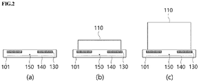
- FIG. 2 illustrates an example in which the size of the display panel 110 is changed through operation of the drive unit 120.
- FIG. 2A illustrates a zero view state in which the display panel 110 is fully rolled down
- FIG. 2B illustrates a partial view state in which the display panel 110 is partially rolled up
- FIG. 2C illustrates a full view state in which the display panel 110 is entirely rolled up such that the entire display panel 110 is fully stretched out of the housing.
- the image display device 100 may offer various functionalities according to changes in the size of the display panel 110.
- one partial view state is illustrated.
- the image display device 100 may have a plurality of partial view states which differ in the height of the display panel 110 according to how much degree the display panel 110 is rolled up.
- the housing 101 has an internal space for accommodating the display panel 110 when the display panel 110 is rolled down.
- the drive unit 120, the motion detection unit 160, and the controller 170 may installed in the internal space of the housing 101.
- the housing 101 is provided with a slit (not shown) through which the display panel 110 can be rolled into and rolled out of the housing.
- the housing 101 may be implemented in any shape and size if the shape and size allow the display panel 110 to be received in the housing 101.
- FIG. 1 illustrates an example in which the housing is implemented in the form of a rectangular shape.
- the housing 101 is provided with a light emitting unit 130, an audio output unit 140 and an image capturing unit 150, each of which may be disposed on the front surface of the housing 101 or on an arbitrary position while facing forward.
- the light emitting unit 130 is a device for emitting light and may be configured with light emitting devices such as light emitting diodes (LEDs).
- the light emitting unit 130 may be configured such that a plurality of light emitting devices is arranged to form predetermined patterns. For example, in FIG. 1 , the light emitting unit 130 is configured such that the light emitting devices are linearly arranged.
- the light emitting unit 130 is one of the output means for providing a welcome feedback signal.
- the welcome feedback refers to visual feedback or audio feedback provided to a user when the image display device 100 detects a motion of a user while the image display device 100 is in the zero view state.
- the controller 170 may provide visual feedback with various colors or patterns by controlling toggles or color changes of the light emitting devices of the light emitting unit 130 when a motion of a user is detected.
- the light emitting unit 130 is disposed toward the front side of the housing 101 so that a user in front of the image display device 100 can easily recognize the welcome feedback.
- the light emitting unit 130 is integrally formed with the front surface of the housing 101.
- the arrangement of the light emitting unit 130 is not limited thereto. That is, the light emitting unit 130 can be disposed at any place if it can face forward so that a user can easily recognize the welcome feedback.
- the light emitting unit 130 can be disposed on the upper surface or the side surface of the housing 101.
- the audio output unit 140 may include a speaker module to output a sound signal.
- the audio output unit 140 is one of the output means for providing the welcome feedback in the form of sound.
- the controller 170 to be described later in detail may perform output an audio signal (i.e., sound) corresponding to welcome feedback to the audio output unit 140 when a motion of a user is detected.
- the welcome feedback is provided through the audio output unit 140.
- the audio output unit 140 is integrally formed on the front surface of the housing 101.
- the arrangement of the audio output unit 140 is not limited thereto.
- the audio output unit 140 can be disposed on the upper surface or the side surface of the housing 101 if sound (i.e., audio signal) can be output toward the front side of the image display device 100.
- the image capturing unit 150 is a device for imaging an object existing in front of the image display device 100.
- the image capturing unit 150 includes an imaging element such as a CCD or a CMOS.
- the image capturing unit 150 may be disposed on the front surface of the housing 101 or disposed to face forward.
- FIG. 1 illustrates an arrangement example in which the image capturing unit 150 is fixed to the center portion of the front surface of the housing 101.
- the image capturing unit 150 is a means for imaging an object in front of the image display device 100 to detect a motion of a user. Therefore, the image capturing unit 150 can be disposed on the upper surface or the side surface of the housing 101 instead of the front surface if it can capture an image of an object existing in front of the image display device 100.
- the motion detection unit 160 detects a motion of a user by analyzing two temporally adjacent frames (i.e., a temporally front frame and a temporally rear frame) captured by the image capturing unit 150.
- the motion detection unit 160 includes an algorithm to process input frames and detect a motion of a user and a processor for executing the algorithm
- the controller 170 controls the light emitting unit 130, the audio output unit 140, and the drive unit 120 according to the results of a motion detection performed by the motion detection unit 160.
- the controller 170 includes a control algorithm, a processor for executing the control algorithm, and a memory in which the control algorithm is stored.
- the controller 170 activates the image capturing unit 150 and the motion detection unit 160 to detect whether there is a motion of a user.
- the motion detection unit 160 When a motion of a user is detected by the motion detection unit 160, at least one of the light emitting unit 130 and the audio output unit 140 is activated to provide a welcome feedback in the form of light or sound.
- the image display device 100 draw a user's attention by sending a welcome message (i.e., welcome feedback).
- a welcome feedback may be provided only when a welcome feedback function is set to ON state.
- the welcome feedback may be provided in various ways.
- the controller 170 may output various forms of welcome feedback by controlling emission colors, brightness, toggles, dimming, etc. of the plurality of light emitting devices of the light emitting unit 130.
- the controller 170 may have a plurality of welcome feedbacks.
- the controller 170 may allow the audio output unit 140 to output a welcome feedback in various forms such as music, specific sound, and human voice.
- first mode in a case where a device that is listed in a device connection history record of the image display device 100 is detected when a user application program such as SmartTinkQ is executed, when a motion of a user is detected, the controller 170 performs control such that both a visual feedback and an audio feedback are provided to the user through the light emitting unit 130 and the audio output unit 140, respectively.
- the controller 170 performs control such that only a visual feedback is provided to the user through the light emitting unit 130
- there are two feedback modes a first mode in which both an audio feedback and a visual feedback are provided to the user when the device that has been connected to the image display device is detected through the user application program; and a second mode in which only a visual feedback is provided to the user when the device that has been connected to the image display device is not detected.
- FIGS. 4 and 5 are schematic views illustrating welcome feedback modes of the image display device 100 according to one exemplary embodiment of the present invention.
- FIG. 4 illustrates a case in which only the visual welcome feedback is provided through the light emitting unit 130. While the image display device 100 is in the zero view state, the light emitting unit 130 remains inactive as illustrated in FIG. 4A . However, when a user motion is detected, the light emitting unit 130 is toggled from the left to the right (i.e., activated), thereby providing the visual welcome feedback as illustrated in FIG. 4B .
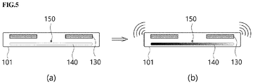
- FIG. 5 illustrates a case in which both the visual feedback and the audio feedback are provided through the light emitting unit 130 and the audio output unit 140. While the image display device 100 is in the zero view state, the light emitting unit 130 and the audio output unit 140 remain inactive. Only when a user motion is detected, the light emitting unit 130 is toggled from the left to the right to provide the visual welcome feedback and the audio output unit 140 is activated to provide the audio welcome feedback, for example, a bell sound of 'Tirori' as shown in FIG. 5B .
- the controller 170 disables the image capturing unit 150 and the motion detection unit 160 for a predetermined period of time or prevents another welcome feedback from being provided for a predetermined period of time even though a motion of a user is detected within the predetermined period of time. For example, when a user motion is detected and a welcome feedback is thus provided, the image display device 100 disables the welcome feedback function for first 30 seconds such that another welcome feedback cannot be provided within this period of time regardless of the detection of another user motion and then enables the welcome feedback function after the first 30 seconds pass. That is, after the first 30 seconds pass, another welcome feedback can be provided according to the results of a motion detection performed by the motion detection unit.
- the controller 170 activates the image capturing unit 150 and the motion detection unit 160 to detect whether there is a user motion.
- the controller controls the drive unit 120 to roll down the display panel 110 so that the display panel 110 is switched from the partial view state or the full view state to the zero view state.
- the power of the image display device 100 is preferably turned off. That is, since the controller detects a user motion in the partial view state of the display panel 110 and switches the display panel 110 to the zero view state and turns off the power, it is possible to reduce power consumption when the image display device 100 is not used.
- the image display device 100 may further include the image capturing unit 150 and a user-input interface unit 180.
- the image capturing unit 150 receives and processes a broadcast signal, or an image signal output from an external device such as a set-top box, a game console, a computer, and the like.
- the image capturing unit 150 may include a tuner (not illustrated) for processing the broadcast signal and an external device interface unit (not illustrated) for connection with an external device.
- the image signal received by the image capturing unit 150 is transmitted to the display panel 110 under control of the controller 170 and displayed on the screen of the display panel 110.
- the user-input interface unit 180 transmits a signal (hereinafter, simply referred to as user input) input by a user to the controller 170 or transmits a signal output from the controller 170 to a user.
- the user-input interface unit may include a module for communication with a remote control to receive the user input.
- a control method of the image display device 100 according to an exemplary embodiment of the present invention will be described in detail with reference to FIGS. 5 and 6 .
- FIG. 6 is a control flow in which a welcome feedback is provided according to a motion detection in the image display device 100 according to one exemplary embodiment of the present invention.
- a controller 170 checks whether a welcome feedback function is set to ON state (S11). When it is determined that the welcome feedback function is set to ON state, the controller 170 activates am image capturing unit 150 and a motion detection unit 160 so that a user motion can be detected (S12).
- the controller 170 checks whether a device that is listed in a connection history record in a user application program is detected (S13), and selects one of the welcome feedback modes according to the results of the checking.
- the controller 170 activates an audio output unit 140 and a light emitting unit 130 so that both of the visual feedback and the audio feedback can be provided through the light emitting unit 130 and the audio output unit 140, respectively (S16).
- the number of times that the welcome feedback is provided may be limited to less than a predetermined value in order to prevent a device operation error attributable to frequent connections with and disconnections from the device from occurring.
- the welcome feedback mode in which both the audio feedback and the visual feedback are provided at the same time can be performed at most twice a day.
- the controller 170 may activate the welcome feedback mode in which only the visual feedback is provided through the light emitting unit 130 when a user motion is detected.
- the controller 170 activates only the light emitting unit 130 to provide only the visual feedback (S17).
- FIG. 7 is a view illustrating a control flow for a case in which a display panel is switched from a partial view state to a zero-view state according to the results of a motion detection in the image display device 100 according to one exemplary embodiment of the present invention.
- a controller 170 activates an image capturing unit 150 and a motion detection unit 160 to detect a user motion (S21) in the partial view state in which a display panel 110 is partially rolled up (S20).
- a user motion S21
- a user-input interface unit 180 controls the display panel 110 to roll the display panel 110 down so that the display panel 110 is switched to the zero view state from the partial view state (S24).
- the predetermined period of time T1 may vary within a range of 3 hours to 5 hours.
- the controller 170 may control the image display device 100 to enter a standby mode (power saving mode).
- the controller 170 may notify the user that the display panel 110 is switched to the zero view state by displaying a notification message indicating state switching instead of directly switching the display panel 110 to the zero view state.
- the user can input a key input to interrupt the state transition.
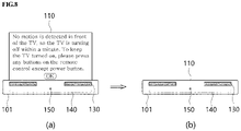
- FIG. 8 schematically illustrates a transition from the partial view state to the zero view state in the image display device 100 according to an exemplary embodiment of the present invention.
- the controller 170 performs control such that the notification message is displayed on the screen of the display panel 110 of the image display device 100 as illustrated in FIG. 8A .
- the controller may perform control such that the display panel 110 is switched to the zero view state as illustrated in FIG. 8B .
- the predetermined period of time T2 may vary, for example, in a range of 1 minute to 3 minutes.
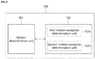
- FIG. 9 is a block diagram of a motion detection unit 160 of the image display device 100 according to one exemplary embodiment of the present invention.
- the motion detection unit 160 of the image display device 100 according to one exemplary embodiment of the present invention includes a motion determination unit 161 and a motion exception determination unit 162.
- the motion determination unit 161 primarily analyzes image frames photographed by the image capturing unit 150 to determine whether there is a user motion.
- the motion determination unit 161 may use various motion detection techniques, such as histogram analysis, which performs analysis by accumulating changes for each block between the image frames.
- the motion determination unit 161 divides each of the input frames into a plurality of blocks, and determines whether there is a user motion on the basis of a change (i.e., difference) in pixel brightness of each block between the image frames that are consecutively input.
- the motion determination unit 161 divides each image frame into 32 ⁇ 24 blocks each being composed of 5 ⁇ 5 pixels, and calculates the average of the brightness values of the pixels within each block.
- an interest block is defined as a block disposed at a certain position in an image frame and a corresponding block is defined as a block positioned at the same position in another image frame (i.e., the subsequent image frame)
- a change in pixel brightness value i.e., change in the average of the brightness values of the respective pixels
- Th1 a predetermined threshold value
- the motion determination unit 161 determines the interest block as a motion block.
- a block that does not satisfy the requirements to be the motion block will be referred to as a motionless block.
- the motion determination unit 161 determines that there is a user motion (i.e., user motion has occurred).
- the block when an event in which the change in the pixel brightness value (i.e., the average of the brightness values of the pixels) is equal to or greater than the predetermined threshold value Th1 occurs consecutively m or more times, it is determined that the block may be determined as a motion block. For example, only when there are m or more consecutive image frames among which the change in the pixel brightness value between the blocks disposed at the same position respectively in the two consecutive image frames is equal to or greater than the predetermined threshold value Th1, the blocks are determined as motion blocks.
- the number n and the number m are variable values that can be arbitrary set.
- the sensitivity of the motion detection can be adjusted according to the values of the numbers n and m. The greater the values of the numbers n and m, the higher the sensitivity.
- the number n is set to be within a range of 1 to 3 and the number m is set to be within a range of 2 to 4, it is confirmed that the performance of the motion detection is improved.
- the predetermined threshold value Th1 may vary from block to block and may be set according to Equation 1.
- Th 1 A + A ⁇ B + C
- Equation 1 A is the overall average of the pixel brightness value differences each of which is a change in pixel brightness value between corresponding blocks in respective two consecutive image frames, B is the minimum value of the pixel brightness value differences, and C represents white or the weight of the brightness of the block.
- Equation 1 the values A and B vary according the brightness value of each frame or each block, and the predetermined threshold value Th1 varies from frame to frame or from block to block.
- the motion exception determination unit 162 functions to handle a motion exception event. That is, the motion exception determination unit 162 determines a sudden change in illuminance or a movement of a periodically moving object as an exception of motion. The motion exception determination unit 162 determines whether there occurs a motion exception event on the basis of at least one of the overall change and a local change in the pixel brightness value between two consecutive image frames.
- the motion exception determination unit 162 includes a first motion exception determination unit 162a for determining a sudden change in illuminance caused by light from a vehicle or any external device as an exception of motion.
- the first motion exception determination unit 162a determines the case where a change in the average pixel brightness value between two consecutive image frames is equal to or greater than a predetermined threshold value Th2 as a motion exception event. That is, the case is not determined as an event in which a user motion has occurred. That is, when the difference in the average pixel brightness value between two consecutive image frames is greater than or equal to the predetermined threshold value Th2, the case is determined to be an event in which the illuminance has suddenly changed and is thus excluded from detection of a user motion.
- the predetermined threshold value Th2 may be set to one value in a range of 1 to 64. As the value of the predetermined threshold value Th2 is increased, the difference value that can be regarded as a motion exception condition attributable to a sudden change in the illuminance is increased. Therefore, the larger the predetermined threshold value Th2, the sensitivity for detection of a motion exception event is lowered.
- the predetermined threshold value Th2 may be appropriately set while considering the influence of the illuminance of the space in the image display device 100 is installed. When the predetermined threshold value Th2 is set to a value within a range of 2 to 5, it is confirmed that it is possible to more easily detect a motion exception event attributable to a sudden change in the illuminance.
- the motion exception determination unit 162 may include a second motion exception determination unit 162b to determine the case where the changes in the average pixel brightness value between every two consecutive image frames among a plurality of image frames sequentially input are periodic, as an exception of motion (i.e., motion exception event) attributable to periodic movements of an object.
- the second motion exception determination unit 162b detects movements of a periodically moving obj ect (for example, a fan, a clock, or a moving accessory) disposed around the image display device 100 and determines the movement as an exception of motion (i.e., motion exception event).
- the motion detection unit 160 further includes a register for storing the results of detection of periodic movements for each of the plurality of blocks. For example, when an image frame is divided into 32 ⁇ 24 blocks, resisters corresponding to as many as the number of the blocks are provided.
- the second motion exception determination unit 162b adds a value of p to the pixel brightness value of each of the motion blocks and stores the sum in a corresponding one of the registers.
- a value of q is added and then the sum is stored in a corresponding one of the registers.
- Th3 the block corresponding to the register is regarded as a motionless block and treated as an exception of motion when detecting a user motion.
- the brightness values of the blocks in the respective frames show periodicity.
- the weight of p and the weight of q are applied to each of the blocks determined to be motion blocks and each of the blocks determined to be motionless blocks, respectively.
- the periodic movement is detected on the basis of the cumulative sum of the values for each block.
- the value of p is set to be considerably greater than the value of q to detect the periodic movement.
- the value of p is set to a value within a range of 9 to 12
- the value of q is set to a value within a range of -3 to 0, and the predetermined threshold value Th3 is set to a value within a range of 140 to 160, it was confirmed that the periodic movement of an object can be detected with good precision.
- the image display device 100 when the image display device 100 according to the present invention detects a user motion, if a change in illuminance attributable to a movement of an object (not a human) or a vehicle light beam is detected, it is not determined as a user motion but processed as a motion exception event. That is, such as a case is excluded from motion detection, thereby preventing erroneous motion detection.
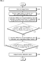
- FIG. 10 is a flowchart illustrating a motion detection method of the image display device 100 according to one exemplary embodiment of the present invention.
- the motion detection unit 160 sequentially receives image frames captured by an image capturing unit 150 (S40). In this step, 12 image frames are input per second.
- the motion detection unit 160 divides each of the image frames into a plurality of blocks and calculates an average value of brightness values of respective pixels in each of the blocks (S41).
- the difference in average pixel brightness value between corresponding blocks within respective two consecutive image frames is calculated (S42).
- Th1 a predetermined threshold value
- the blocks are determined as motion blocks.
- the number of the motion blocks is n or more, it is determined that there is a motion of a user.
- the number of the motion blocks is less than n, it is determined that there is no motion of a user.
- the difference in the overall pixel brightness value between each of the consecutive image frames is calculated (S34).
- a predetermined threshold value Th2 this case is determined as an exception of motion and is excluded from detection of a user motion (S35). This corresponds to the function of the first motion exception processing unit.
- Th2 the difference in the overall pixel brightness value between two consecutive image frames is equal to or greater than the predetermined threshold value Th2
- this case is determined that there is a sudden change in illumination and is thus excluded from detection of a user motion (i.e., the case is determined as a motion exception event).
- a motion detection signal is output (S36).
- FIG. 11 is a flowchart illustrating a motion detection method of the image display device 100 according to one exemplary embodiment of the present invention.
- the motion detection unit 160 receives image frames captured by the image capturing unit 150 (S40), divides each of the image frames into a plurality of blocks, and calculates a pixel brightness value of each block (S41).
- the pixel brightness value of each block means the average of the brightness values of all the pixels in each block
- the difference in the pixel brightness value of each block i.e., the average of the brightness values of all the pixels in each block
- the block is determined to be a motion block A block that is not a motion block is referred to as a motionless block for sake of convenient description).
- the predetermined threshold value Th1 may vary from block to block or frame to frame.
- the predetermined threshold value Th1 may be determined according to Equation 1.
- the motion detection unit 160 applies different weights to the motion blocks and the motionless blocks, respectively, and the cumulative sum of the pixel brightness values of each block is stored in a corresponding one of the registers. For example, a value of p is added to the value stored in a register corresponding to a motion block, and a value of q is added to the value stored in a register corresponding to a motionless block (S44).
- the block is determined as an exception of motion and is determined to be a motionless block (S45).
- This process corresponds to the function of the second motion exception processing unit described above.
- this movement is regarded as a periodic motion of an object. In this case, the motion is determined as an exception of motion.
- Step S46 when it is determined that there is a motion of a user, a difference in overall pixel brightness value (i.e., the average of brightness values of all the pixels in one image frame) between the image frame and the subsequent image frame is calculated (S47).
- a difference in overall pixel brightness value between the image frame and the subsequent image frame is equal to or greater than a predetermined threshold value Th2 (S48)
- Th2 a predetermined threshold value
- a motion detection signal is output (S49).
- a motion of a user existing in front of the image display device 100 is detected, and then a welcome feedback is provided to the user or the image display device is switched to the zero view state.
- motion exception events in which a change in pixel brightness value attributable to a sudden change in illuminance or a periodic movement of an object is regarded as an exception of motion detection are determined. This has an advantage of preventing unexpected activation of the image display device.
- the operation method of the image display device 100 may be implemented in the form of a code that is stored in a processor-readable recording medium provided in the image display device 100.
- the processor-readable recording medium include all kinds of recording devices that can store data that can be read by a processor.
- Specific examples of the processor-readable recording medium include a ROM, a RAM, a CD-ROM, a magnetic tape, a floppy disk, an optical data storage device, and the like.
- the processor-readable recording medium may be implemented in the form of a carrier wave for transmission of a signal over the Internet.
- the processor-readable recording medium may also be distributed over computer systems connected via a network, and the code may be stored and executed in the distributed processor-readable recording medium.
Landscapes
- Engineering & Computer Science (AREA)
- Physics & Mathematics (AREA)
- General Physics & Mathematics (AREA)
- Theoretical Computer Science (AREA)
- Computer Hardware Design (AREA)
- Multimedia (AREA)
- Computer Vision & Pattern Recognition (AREA)
- Control Of Indicators Other Than Cathode Ray Tubes (AREA)
Applications Claiming Priority (1)
| Application Number | Priority Date | Filing Date | Title |
|---|---|---|---|
| PCT/KR2019/008988 WO2021015309A1 (ko) | 2019-07-19 | 2019-07-19 | 영상표시장치 및 영상표시장치의 모션감지방법 |
Publications (2)
| Publication Number | Publication Date |
|---|---|
| EP4002063A1 true EP4002063A1 (de) | 2022-05-25 |
| EP4002063A4 EP4002063A4 (de) | 2023-11-01 |
Family
ID=74192549
Family Applications (1)
| Application Number | Title | Priority Date | Filing Date |
|---|---|---|---|
| EP19938654.1A Pending EP4002063A4 (de) | 2019-07-19 | 2019-07-19 | Bildanzeigevorrichtung und verfahren zur bewegungsdetektion einer bildanzeigevorrichtung |
Country Status (4)
| Country | Link |
|---|---|
| US (2) | US11587483B2 (de) |
| EP (1) | EP4002063A4 (de) |
| KR (1) | KR102814641B1 (de) |
| WO (1) | WO2021015309A1 (de) |
Families Citing this family (6)
| Publication number | Priority date | Publication date | Assignee | Title |
|---|---|---|---|---|
| CN109683844A (zh) * | 2019-01-11 | 2019-04-26 | 京东方科技集团股份有限公司 | 条形屏控制电路、条形屏显示系统以及条形屏控制方法 |
| EP4002063A4 (de) | 2019-07-19 | 2023-11-01 | LG Electronics Inc. | Bildanzeigevorrichtung und verfahren zur bewegungsdetektion einer bildanzeigevorrichtung |
| US20250123671A1 (en) * | 2021-09-08 | 2025-04-17 | Lg Electronics Inc. | Display device |
| WO2025053294A1 (ko) * | 2023-09-04 | 2025-03-13 | 엘지전자 주식회사 | 무선 전송 장치 및 무선 디스플레이 시스템 |
| KR102852148B1 (ko) * | 2024-10-31 | 2025-08-29 | 주식회사 스포클립에이아이 | 챌린지 참여 데이터를 기초로 하는 랭킹 산정 시스템 및 그 방법 |
| KR102852147B1 (ko) * | 2024-11-01 | 2025-08-29 | 주식회사 스포클립에이아이 | Ai를 기반으로 스포츠 챌린지 리워드를 결정하는 장치 및 방법 |
Family Cites Families (17)
| Publication number | Priority date | Publication date | Assignee | Title |
|---|---|---|---|---|
| EP1418555B1 (de) * | 1999-12-17 | 2007-10-10 | Siemens Schweiz AG | Präsenzmelder und dessen Verwendung |
| US9655267B2 (en) * | 2008-01-04 | 2017-05-16 | Nanolumens Acquisition, Inc. | Retractable display system and method of use |
| KR101148787B1 (ko) * | 2010-01-18 | 2012-05-24 | 한국과학기술원 | 퍼블릭 디스플레이 방법, 장치 및 시스템 |
| KR20130058275A (ko) * | 2011-11-25 | 2013-06-04 | 현대자동차주식회사 | 스마트 avn 웰컴 시스템 |
| KR101383092B1 (ko) * | 2012-06-27 | 2014-04-17 | 삼성디스플레이 주식회사 | 표시 장치 및 이의 구동 방법 |
| KR102070244B1 (ko) * | 2012-08-01 | 2020-01-28 | 삼성전자주식회사 | 플렉서블 디스플레이 장치 및 그 제어 방법 |
| KR20140091319A (ko) * | 2013-01-11 | 2014-07-21 | 이정남 | Led 조명등 제어장치 |
| KR101570869B1 (ko) * | 2014-12-31 | 2015-11-23 | 엘지디스플레이 주식회사 | 롤러블 디스플레이 장치 |
| KR102398162B1 (ko) * | 2015-02-10 | 2022-05-17 | 삼성디스플레이 주식회사 | 롤러블 표시장치 |
| US9772657B2 (en) * | 2015-04-30 | 2017-09-26 | Samsung Electronics Co., Ltd. | Rollable display device |
| KR102469625B1 (ko) * | 2015-10-13 | 2022-11-22 | 엘지전자 주식회사 | 디스플레이 디바이스 |
| KR102387115B1 (ko) * | 2015-11-18 | 2022-04-18 | 삼성전자주식회사 | 전자 장치 및 이의 제어 방법 |
| KR102436558B1 (ko) * | 2016-04-28 | 2022-08-26 | 엘지디스플레이 주식회사 | 두루마리형 연성표시장치 |
| WO2018016095A1 (ja) * | 2016-07-19 | 2018-01-25 | Gatebox株式会社 | 画像表示装置、話題選択方法、話題選択プログラム、画像表示方法及び画像表示プログラム |
| WO2019039634A1 (ko) * | 2017-08-25 | 2019-02-28 | 엘지전자 주식회사 | 영상표시장치 |
| US11071218B2 (en) * | 2019-04-10 | 2021-07-20 | Apple Inc. | Electronic devices having sliding expandable displays |
| EP4002063A4 (de) | 2019-07-19 | 2023-11-01 | LG Electronics Inc. | Bildanzeigevorrichtung und verfahren zur bewegungsdetektion einer bildanzeigevorrichtung |
-
2019
- 2019-07-19 EP EP19938654.1A patent/EP4002063A4/de active Pending
- 2019-07-19 WO PCT/KR2019/008988 patent/WO2021015309A1/ko not_active Ceased
- 2019-07-19 KR KR1020227005234A patent/KR102814641B1/ko active Active
-
2020
- 2020-07-15 US US16/929,851 patent/US11587483B2/en active Active
-
2022
- 2022-09-12 US US17/942,993 patent/US11721257B2/en active Active
Also Published As
| Publication number | Publication date |
|---|---|
| KR102814641B1 (ko) | 2025-05-29 |
| EP4002063A4 (de) | 2023-11-01 |
| WO2021015309A1 (ko) | 2021-01-28 |
| US11721257B2 (en) | 2023-08-08 |
| US20230005403A1 (en) | 2023-01-05 |
| US11587483B2 (en) | 2023-02-21 |
| KR20220037466A (ko) | 2022-03-24 |
| US20210020088A1 (en) | 2021-01-21 |
Similar Documents
| Publication | Publication Date | Title |
|---|---|---|
| US11721257B2 (en) | Image display device and motion detection method of image display device | |
| US11863859B2 (en) | Electronic system with eye protection in response to user distance | |
| CN113632441B (zh) | 一种光传感器状态控制方法及电子设备 | |
| JP5263092B2 (ja) | 表示装置および制御方法 | |
| JP4203736B2 (ja) | 画像の動き検出装置及びコンピュータプログラム | |
| US20200336661A1 (en) | Video recording and processing method and electronic device | |
| US10805579B2 (en) | Motion detection methods and motion sensors capable of more accurately detecting true motion event | |
| GB2424785A (en) | Motion-dependent surveillance recording | |
| JP2012133524A (ja) | 画像表示制御装置および画像表示制御方法 | |
| US12229986B2 (en) | Information processing apparatus, information processing method, and storage medium for displaying am image indicating a pixel where a luminance change occurs based on a signal | |
| EP2987540B1 (de) | Informationsverarbeitungsvorrichtung, Informationsverarbeitungssystem, Informationsverarbeitungsprogramm, und Informationsverarbeitungsverfahren | |
| CN106169290A (zh) | 控制方法、控制装置及电子装置 | |
| CN108989638B (zh) | 成像装置及其控制方法、电子装置和计算机可读存储介质 | |
| JP2011039157A (ja) | 表示装置 | |
| US20230131669A1 (en) | Background dimming with gaze detection | |
| JP2007310096A (ja) | 映像表示装置、及びその表示輝度調整方法 | |
| CN109740528B (zh) | 图像处理方法、电子设备以及可读存储介质 | |
| US12604103B2 (en) | Multi-factor assessment to detect image capture device smudges and corresponding electronic devices and methods | |
| JP2008199105A (ja) | 撮像装置および撮像処理方法 | |
| JP2026064550A (ja) | 画像処理装置および画像処理方法、ならびに撮像システム | |
| CN106200934A (zh) | 控制方法、控制装置及电子装置 | |
| JP2007316689A (ja) | 画像センサ装置 |
Legal Events
| Date | Code | Title | Description |
|---|---|---|---|
| STAA | Information on the status of an ep patent application or granted ep patent |
Free format text: STATUS: THE INTERNATIONAL PUBLICATION HAS BEEN MADE |
|
| PUAI | Public reference made under article 153(3) epc to a published international application that has entered the european phase |
Free format text: ORIGINAL CODE: 0009012 |
|
| STAA | Information on the status of an ep patent application or granted ep patent |
Free format text: STATUS: REQUEST FOR EXAMINATION WAS MADE |
|
| 17P | Request for examination filed |
Effective date: 20211221 |
|
| AK | Designated contracting states |
Kind code of ref document: A1 Designated state(s): AL AT BE BG CH CY CZ DE DK EE ES FI FR GB GR HR HU IE IS IT LI LT LU LV MC MK MT NL NO PL PT RO RS SE SI SK SM TR |
|
| DAV | Request for validation of the european patent (deleted) | ||
| DAX | Request for extension of the european patent (deleted) | ||
| RIC1 | Information provided on ipc code assigned before grant |
Ipc: G09F 9/30 20060101ALI20230620BHEP Ipc: G06F 1/16 20060101ALI20230620BHEP Ipc: G06F 3/00 20060101ALI20230620BHEP Ipc: G06F 3/01 20060101AFI20230620BHEP |
|
| A4 | Supplementary search report drawn up and despatched |
Effective date: 20230928 |
|
| RIC1 | Information provided on ipc code assigned before grant |
Ipc: G09F 9/30 20060101ALI20230922BHEP Ipc: G06F 1/16 20060101ALI20230922BHEP Ipc: G06F 3/00 20060101ALI20230922BHEP Ipc: G06F 3/01 20060101AFI20230922BHEP |
|
| STAA | Information on the status of an ep patent application or granted ep patent |
Free format text: STATUS: EXAMINATION IS IN PROGRESS |
|
| 17Q | First examination report despatched |
Effective date: 20260320 |