EP4002067A1 - Procédé de préparation d'un balayage 3d et balayeur 3d destiné à la mise en uvre du procédé - Google Patents
Procédé de préparation d'un balayage 3d et balayeur 3d destiné à la mise en uvre du procédé Download PDFInfo
- Publication number
- EP4002067A1 EP4002067A1 EP21206400.0A EP21206400A EP4002067A1 EP 4002067 A1 EP4002067 A1 EP 4002067A1 EP 21206400 A EP21206400 A EP 21206400A EP 4002067 A1 EP4002067 A1 EP 4002067A1
- Authority
- EP
- European Patent Office
- Prior art keywords
- scanner
- control
- evaluation unit
- cameras
- object space
- Prior art date
- Legal status (The legal status is an assumption and is not a legal conclusion. Google has not performed a legal analysis and makes no representation as to the accuracy of the status listed.)
- Granted
Links
Images


Classifications
-
- G—PHYSICS
- G06—COMPUTING OR CALCULATING; COUNTING
- G06F—ELECTRIC DIGITAL DATA PROCESSING
- G06F3/00—Input arrangements for transferring data to be processed into a form capable of being handled by the computer; Output arrangements for transferring data from processing unit to output unit, e.g. interface arrangements
- G06F3/01—Input arrangements or combined input and output arrangements for interaction between user and computer
- G06F3/017—Gesture based interaction, e.g. based on a set of recognized hand gestures
Definitions
- the invention relates to a method for preparing a 3D scan of at least part of a surface of an object.
- 3D scanners are known from the prior art. These use 3D sensors whose function is based on optical triangulation processes.
- an object to be measured is illuminated with a series of structured patterns using a projector.
- a camera records the projected pattern, which is distorted by the surface of the object to be measured.
- the three-dimensional (3D) nature of the object to be measured can be determined from the distortion of the pattern in the recorded camera image.
- This method allows the 3D nature of the object to be recorded relatively precisely. However, this method depends on the object not moving between the projection of the individual structured patterns. A quick detection of moving and non-stationary objects is therefore not possible.
- a measurement of the 3D condition of an object is triggered by the user via a selection within the graphical user interface of a software.
- Manual operation via the software's user interface is error-prone and not intuitive.
- the user must select the type of object to be scanned and the area to be scanned and place the object manually in the detection area of the 3D scanner's sensors.
- the manual placement of the object is naturally not particularly precise, especially when the nature of the objects changes frequently objects.
- the software selects a so-called scan strategy from a database based on categories and uses this to capture the object via the sensors of the 3D scanner.
- the scanning strategy describes, among other things, from which directions an object is successively captured by the 3D sensor system in order to enable a complete capture of the 3D condition of the object. Due to shadowing, objects with complex surfaces have areas that can only be detected from a few specific directions. Therefore, a scan strategy with several scan directions is selected by the user in the software for objects with complex 3D properties. However, as described, these scanning strategies are only assigned to object categories in which objects with complex 3D properties are detected from a greater number of different directions than objects with less complex 3D properties. However, the complexity of the surface of an object to be recorded can differ within an object category, possibly even without this difference being apparent to the user. An individual, optimized adaptation of the scanning strategy to the complexity of the 3D properties of the object to be measured is not possible with these methods. An optimal scan strategy defines a minimum number of scan directions so that the object to be measured or at least a specified area of it is completely captured by the 3D sensor system with the desired accuracy.
- the two cameras record almost the same space.
- the optical axes of the two cameras can be directed towards a common point inside or outside the object space. If the two cameras have a large detection area, the optical axes can also run parallel. As with human vision, this allows a stereoscopic image to be calculated, which enables a 3D height map of the detected area to be determined. Since the two cameras are controlled and read synchronously by the control and evaluation unit, moving objects can also be recorded. This 3D stereo camera system can thus capture the nature of the object as well as its position and orientation in the object space of the 3D scanner quickly and while it is moving.
- the method according to the invention makes it possible to recognize the type of object to be scanned and to identify possible shadowing and thus to evaluate an optimal scanning strategy.
- Other applications are conceivable without deviating from the idea on which the invention is based.
- a development of the invention provides that after the nature of the object and its position and orientation in the object space based on of the image recordings, the object is aligned by means of the object carrier in the object space in such a way that it is optimally arranged in the detection area of a 3D sensor system assigned to the 3D scanner.
- the object carrier is movably arranged in the object space via a suitable drive. The drive is controlled by the control and evaluation unit of the 3D scanner. In this way, the object can be automatically positioned in the detection area of the 3D sensor system, so that the respective area of the object's surface to be scanned is recorded in the best possible way.
- the positioning of the object can be carried out again after a first scanning process for at least one further scanning process, so that according to the scanning strategy in the further scanning process an area is scanned that was not or only insufficiently covered in the previous positioning, e.g. because it was outside the field of view of the 3D sensors or by the structure of the object from the perspective taken in the previous positioning.
- a further development of the method according to the invention provides that an operator of the 3D scanner manually points to a specific area in the object space with a finger or delimits a specific area by moving the finger, with this gesture being recorded by the cameras and the control and evaluation unit and is taken into account when aligning the slide and/or determining the scanning strategy.
- the operator's finger and possibly the movement of the finger is also recorded.
- the orientation of the finger and/or a movement of the finger can be determined and the area to which the finger is pointing can thus be detected.
- This gesture can be taken into account when determining the scanning strategy.
- the method according to the invention thus enables intuitive gesture control for the first time.
- other interactions are also possible via gesture control, such as controlling the positioning of the slide or a start signal for the start of the scanning process.
- a development of the invention provides that by means of a light projection system and by means of the control and evaluation unit that Controls the light projection system, which is illuminated by the area determined by the gesture. This provides immediate feedback to the operator identifying the area determined based on the gesture. If the area desired by the operator has not been identified, the user will be made aware of this and can adjust the setting.
- a development of the invention provides that a control panel is projected onto a surface in the object space by means of the light projection system and by means of the control and evaluation unit.
- the operator can use the control panel to make settings for the 3D scanner and/or start the scanning process. For example, he uses his finger to operate it. The position and orientation of the finger is recorded as described above and can be assigned to a function displayed on the control panel. An additional graphical interface via a screen or similar is therefore not required.
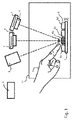
- figure 1 1 shows a schematic of a first exemplary embodiment in which two cameras 1, 2 are arranged stereoscopically.
- the cameras 1, 2 have imaging lenses 3,4 in front.
- a light projection system 5 is also shown.
- the optical axes of the cameras 1, 2 are directed to a common point in an object space 14 of the 3D scanner.
- an object carrier 7 that can be moved by means of a control and evaluation unit 9 is arranged in the object space 14 .
- An object 6 to be scanned is positioned on the object carrier 7 and consists here of four tooth models 6a, 6b, 6c, 6d.
- the control and evaluation unit 9 is communicatively connected to the cameras 1, 2, the light projection system 5 and the slide 7.
- the two cameras 1, 2 synchronously create images of the object 6. Based on the images, the control and evaluation unit 9 is used to determine the 3D nature of the object 6 as well as its position and orientation in the object space. Based on this evaluation, the scanning strategy for the subsequent scanning process can be determined. Movements of the object 6 in the object space 14 can also be detected by repeated synchronous image recordings by the two cameras 1, 2.
- figure 1 a hand 8 whose index finger points to one of the four teeth 6b, the nature of which is of particular interest to the user.
- This gesture is also recorded by the cameras 1, 2 and the tooth model 6b is marked as the area in which the tooth model 6b is located. This area can be given special consideration when subsequently determining the scanning strategy.
- the light projection system 5 also illuminates this area so that the user has direct feedback as to whether his gesture was recorded as desired.
- the scanning process itself can either also be carried out by the two cameras 1, 2 or an additional 3D sensor system (cf. 3 and 4 ).
- FIG. 1 schematically shows a further possible application of the light projection system 5.
- a control panel 10 is imaged onto a surface in the object space 14 by means of the light projection system 5.
- FIG. The operator can point to a projected operating element of the control panel 10 with his finger or touch the surface in the area of the control panel 10, similar to pressing a button.
- This gesture is recorded by the cameras 1, 2 and evaluated accordingly as a control signal, for example "start of the scanning process” or "repositioning of the object”.
- a 3D sensor system 11 with a detection area 12 is also shown.
- the rough 3D condition and the position and orientation of the object 6 in the object space 14 has been determined, areas that are only insufficiently detected by the 3D sensor 11, such as shadows 13, can be determined.
- the object 6 can then be aligned relative to the 3D sensor system 11 via the control and evaluation unit 9 by means of the object carrier 7 in the object space 14 so that the object 6 is in the desired position Alignment is in the detection area 12 of the 3D sensors 11 and no shadowing 13 occur in the area to be scanned.
- figure 4 shows a very similar embodiment to figure 3 .
- the object 6 is not a tooth model but an impression 6e, ie a negative model of the four teeth.
- the object 6 is not a tooth model but an impression 6e, ie a negative model of the four teeth.
- the object 6 is not a tooth model but an impression 6e, ie a negative model of the four teeth.
- the 3D sensor system 11 Given the oblique viewing angle of the 3D sensor system 11, relatively large shadows 13 occur on the object 6, which cannot be detected by the 3D sensor system 11.
- an adaptation of the alignment of the object 6 is necessary in this exemplary embodiment.
- the rough 3D nature of the object 6 is first determined by means of the two cameras 1, 2.
- the shadings 13 can also be determined from different perspectives on the basis of the 3D structure. Taking into account these shadows 13 relative to the line of sight, the control and evaluation unit 9 can be used to determine optimal alignments of the object 6 relative to the 3D sensor system 11 and the object 6 can be
Landscapes
- Engineering & Computer Science (AREA)
- General Engineering & Computer Science (AREA)
- Theoretical Computer Science (AREA)
- Human Computer Interaction (AREA)
- Physics & Mathematics (AREA)
- General Physics & Mathematics (AREA)
- Length Measuring Devices By Optical Means (AREA)
Applications Claiming Priority (1)
| Application Number | Priority Date | Filing Date | Title |
|---|---|---|---|
| DE102020129923.0A DE102020129923B4 (de) | 2020-11-12 | 2020-11-12 | Verfahren zur Vorbereitung eines 3D-Scans und 3D-Scanner zur Durchführung des Verfahrens |
Publications (3)
| Publication Number | Publication Date |
|---|---|
| EP4002067A1 true EP4002067A1 (fr) | 2022-05-25 |
| EP4002067C0 EP4002067C0 (fr) | 2023-10-11 |
| EP4002067B1 EP4002067B1 (fr) | 2023-10-11 |
Family
ID=78528681
Family Applications (1)
| Application Number | Title | Priority Date | Filing Date |
|---|---|---|---|
| EP21206400.0A Active EP4002067B1 (fr) | 2020-11-12 | 2021-11-04 | Procédé de préparation d'un balayage 3d et balayeur 3d destiné à la mise en oeuvre du procédé |
Country Status (2)
| Country | Link |
|---|---|
| EP (1) | EP4002067B1 (fr) |
| DE (1) | DE102020129923B4 (fr) |
Citations (1)
| Publication number | Priority date | Publication date | Assignee | Title |
|---|---|---|---|---|
| US20080306709A1 (en) * | 2004-07-23 | 2008-12-11 | 3Shape A/S | Adaptive 3D Scanning |
Family Cites Families (4)
| Publication number | Priority date | Publication date | Assignee | Title |
|---|---|---|---|---|
| DE102010014423A1 (de) | 2010-03-31 | 2011-10-06 | Carl Zeiss Industrielle Messtechnik Gmbh | Starten einer Messprozedur zum Messen von Koordinaten eines Werkstücks |
| US10401144B2 (en) | 2011-12-06 | 2019-09-03 | Hexagon Technology Center Gmbh | Coordinate measuring machine having a camera |
| DE102012103934B3 (de) | 2012-05-04 | 2013-08-29 | Carl Zeiss Industrielle Messtechnik Gmbh | Optischer Tastkopf für ein Koordinatenmessgerät |
| DE102015116853A1 (de) | 2015-10-05 | 2017-04-06 | Carl Zeiss Industrielle Messtechnik Gmbh | Computerimplementiertes Verfahren und Verfahren zum Betreiben eines Koordinatenmessgeräts |
-
2020
- 2020-11-12 DE DE102020129923.0A patent/DE102020129923B4/de active Active
-
2021
- 2021-11-04 EP EP21206400.0A patent/EP4002067B1/fr active Active
Patent Citations (1)
| Publication number | Priority date | Publication date | Assignee | Title |
|---|---|---|---|---|
| US20080306709A1 (en) * | 2004-07-23 | 2008-12-11 | 3Shape A/S | Adaptive 3D Scanning |
Also Published As
| Publication number | Publication date |
|---|---|
| DE102020129923B4 (de) | 2022-06-15 |
| DE102020129923A1 (de) | 2022-05-12 |
| EP4002067C0 (fr) | 2023-10-11 |
| EP4002067B1 (fr) | 2023-10-11 |
Similar Documents
| Publication | Publication Date | Title |
|---|---|---|
| DE69428686T2 (de) | Bildaufnahmevorrichtung und verfahren zur bestimmung von fokusinformationen | |
| EP3278302B1 (fr) | Système de mesure de déplacement d'une machine et procédé de fonctionnement du système de mesure de déplacement | |
| DE3822057C2 (fr) | ||
| DE69826753T2 (de) | Optischer Profilsensor | |
| DE102014206309B4 (de) | System und Verfahren zum Erhalten von Bildern mit Versatz zur Verwendung für verbesserte Kantenauflösung | |
| DE102008016215A1 (de) | Informationsvorrichtungsbediengerät | |
| DE102007054906A1 (de) | Verfahren zur optischen Vermessung der dreidimensionalen Geometrie von Objekten | |
| DE102018113589A1 (de) | Vorrichtung und Programm zur Positionserfassung | |
| DE102004058655B4 (de) | Verfahren und Anordnung zum Messen von Geometrien eines Objektes mittels eines Koordinatenmessgerätes | |
| EP1022541A2 (fr) | Procédé et dispositif pour déterminer la forme géométrique de matériau en feuilles ou de feuiles empilées | |
| WO2009018894A1 (fr) | Procédé et dispositif de détermination de données géométriques d'un objet mesuré | |
| EP1910999B1 (fr) | Procede et dispositif pour determiner la position relative d'un premier objet par rapport a un second objet, programme informatique correspondant, et support d'enregistrement correspondant, lisible par ordinateur | |
| DE69630025T2 (de) | Kontrolle eines Infrarotmikroskops | |
| EP4002067B1 (fr) | Procédé de préparation d'un balayage 3d et balayeur 3d destiné à la mise en oeuvre du procédé | |
| DE112015006181T5 (de) | Ladungsträgerstrahlvorrichtung, Ausrichtungsverfahren für die L.adungsträgerstrahlvorrichtung, Ausrichtungsprogramm und Speichermedium | |
| DE102017122627A1 (de) | Optisches Messsystem und Messverfahren | |
| DE60115013T2 (de) | Messung der ausrichtung von fahrzeugrädern mit videokameras und wiederholten näherungsrechnungen | |
| DE102017207063A1 (de) | Steuereinrichtung für eine Prüfvorrichtung, Prüfanordnung mit der Steuereinrichtung, Verfahren zur Ansteuerung der Prüfanordnung und Computerprogramm | |
| EP4569371A1 (fr) | Dispositif et procédé de mesure d'images virtuelles tridimensionnelles et d'objets sur un affichage tête haute | |
| WO2014114663A1 (fr) | Dispositif optique et procédé pour déterminer par triangulation de deux caméras linéaires les coordonnées spatiales de surfaces d'objets macroscopiques | |
| WO2013017618A1 (fr) | Balayage optique de surface à éclairage structuré | |
| EP4440405A1 (fr) | Dispositif de mesure et procédé de mesure pour vérifier un état d'image mesurée | |
| DE102004046752B4 (de) | Verfahren zur dreidimensionalen Erfassung von Messobjekten | |
| EP3798570B1 (fr) | Procédé d'étalonnage d'un système de mesure optique, système de mesure optique et objet d'étalonnage pour un système de mesure optique | |
| DE102017000454B4 (de) | Verfahren und System zum Kalibrieren von Bilddaten zweier Kameras |
Legal Events
| Date | Code | Title | Description |
|---|---|---|---|
| PUAI | Public reference made under article 153(3) epc to a published international application that has entered the european phase |
Free format text: ORIGINAL CODE: 0009012 |
|
| STAA | Information on the status of an ep patent application or granted ep patent |
Free format text: STATUS: THE APPLICATION HAS BEEN PUBLISHED |
|
| AK | Designated contracting states |
Kind code of ref document: A1 Designated state(s): AL AT BE BG CH CY CZ DE DK EE ES FI FR GB GR HR HU IE IS IT LI LT LU LV MC MK MT NL NO PL PT RO RS SE SI SK SM TR |
|
| STAA | Information on the status of an ep patent application or granted ep patent |
Free format text: STATUS: REQUEST FOR EXAMINATION WAS MADE |
|
| 17P | Request for examination filed |
Effective date: 20221116 |
|
| RBV | Designated contracting states (corrected) |
Designated state(s): AL AT BE BG CH CY CZ DE DK EE ES FI FR GB GR HR HU IE IS IT LI LT LU LV MC MK MT NL NO PL PT RO RS SE SI SK SM TR |
|
| GRAP | Despatch of communication of intention to grant a patent |
Free format text: ORIGINAL CODE: EPIDOSNIGR1 |
|
| STAA | Information on the status of an ep patent application or granted ep patent |
Free format text: STATUS: GRANT OF PATENT IS INTENDED |
|
| INTG | Intention to grant announced |
Effective date: 20230425 |
|
| GRAS | Grant fee paid |
Free format text: ORIGINAL CODE: EPIDOSNIGR3 |
|
| GRAA | (expected) grant |
Free format text: ORIGINAL CODE: 0009210 |
|
| STAA | Information on the status of an ep patent application or granted ep patent |
Free format text: STATUS: THE PATENT HAS BEEN GRANTED |
|
| AK | Designated contracting states |
Kind code of ref document: B1 Designated state(s): AL AT BE BG CH CY CZ DE DK EE ES FI FR GB GR HR HU IE IS IT LI LT LU LV MC MK MT NL NO PL PT RO RS SE SI SK SM TR |
|
| REG | Reference to a national code |
Ref country code: GB Ref legal event code: FG4D Free format text: NOT ENGLISH |
|
| REG | Reference to a national code |
Ref country code: CH Ref legal event code: EP |
|
| REG | Reference to a national code |
Ref country code: DE Ref legal event code: R096 Ref document number: 502021001683 Country of ref document: DE |
|
| REG | Reference to a national code |
Ref country code: IE Ref legal event code: FG4D Free format text: LANGUAGE OF EP DOCUMENT: GERMAN |
|
| U01 | Request for unitary effect filed |
Effective date: 20231102 |
|
| U07 | Unitary effect registered |
Designated state(s): AT BE BG DE DK EE FI FR IT LT LU LV MT NL PT SE SI Effective date: 20231108 |
|
| U20 | Renewal fee for the european patent with unitary effect paid |
Year of fee payment: 3 Effective date: 20231212 |
|
| PG25 | Lapsed in a contracting state [announced via postgrant information from national office to epo] |
Ref country code: GR Free format text: LAPSE BECAUSE OF FAILURE TO SUBMIT A TRANSLATION OF THE DESCRIPTION OR TO PAY THE FEE WITHIN THE PRESCRIBED TIME-LIMIT Effective date: 20240112 |
|
| PG25 | Lapsed in a contracting state [announced via postgrant information from national office to epo] |
Ref country code: IS Free format text: LAPSE BECAUSE OF FAILURE TO SUBMIT A TRANSLATION OF THE DESCRIPTION OR TO PAY THE FEE WITHIN THE PRESCRIBED TIME-LIMIT Effective date: 20240211 |
|
| PG25 | Lapsed in a contracting state [announced via postgrant information from national office to epo] |
Ref country code: ES Free format text: LAPSE BECAUSE OF FAILURE TO SUBMIT A TRANSLATION OF THE DESCRIPTION OR TO PAY THE FEE WITHIN THE PRESCRIBED TIME-LIMIT Effective date: 20231011 |
|
| PG25 | Lapsed in a contracting state [announced via postgrant information from national office to epo] |
Ref country code: IS Free format text: LAPSE BECAUSE OF FAILURE TO SUBMIT A TRANSLATION OF THE DESCRIPTION OR TO PAY THE FEE WITHIN THE PRESCRIBED TIME-LIMIT Effective date: 20240211 Ref country code: GR Free format text: LAPSE BECAUSE OF FAILURE TO SUBMIT A TRANSLATION OF THE DESCRIPTION OR TO PAY THE FEE WITHIN THE PRESCRIBED TIME-LIMIT Effective date: 20240112 Ref country code: ES Free format text: LAPSE BECAUSE OF FAILURE TO SUBMIT A TRANSLATION OF THE DESCRIPTION OR TO PAY THE FEE WITHIN THE PRESCRIBED TIME-LIMIT Effective date: 20231011 |
|
| PG25 | Lapsed in a contracting state [announced via postgrant information from national office to epo] |
Ref country code: RS Free format text: LAPSE BECAUSE OF FAILURE TO SUBMIT A TRANSLATION OF THE DESCRIPTION OR TO PAY THE FEE WITHIN THE PRESCRIBED TIME-LIMIT Effective date: 20231011 Ref country code: PL Free format text: LAPSE BECAUSE OF FAILURE TO SUBMIT A TRANSLATION OF THE DESCRIPTION OR TO PAY THE FEE WITHIN THE PRESCRIBED TIME-LIMIT Effective date: 20231011 Ref country code: NO Free format text: LAPSE BECAUSE OF FAILURE TO SUBMIT A TRANSLATION OF THE DESCRIPTION OR TO PAY THE FEE WITHIN THE PRESCRIBED TIME-LIMIT Effective date: 20240111 Ref country code: HR Free format text: LAPSE BECAUSE OF FAILURE TO SUBMIT A TRANSLATION OF THE DESCRIPTION OR TO PAY THE FEE WITHIN THE PRESCRIBED TIME-LIMIT Effective date: 20231011 |
|
| REG | Reference to a national code |
Ref country code: DE Ref legal event code: R097 Ref document number: 502021001683 Country of ref document: DE |
|
| PG25 | Lapsed in a contracting state [announced via postgrant information from national office to epo] |
Ref country code: CZ Free format text: LAPSE BECAUSE OF FAILURE TO SUBMIT A TRANSLATION OF THE DESCRIPTION OR TO PAY THE FEE WITHIN THE PRESCRIBED TIME-LIMIT Effective date: 20231011 |
|
| PG25 | Lapsed in a contracting state [announced via postgrant information from national office to epo] |
Ref country code: SK Free format text: LAPSE BECAUSE OF FAILURE TO SUBMIT A TRANSLATION OF THE DESCRIPTION OR TO PAY THE FEE WITHIN THE PRESCRIBED TIME-LIMIT Effective date: 20231011 |
|
| PG25 | Lapsed in a contracting state [announced via postgrant information from national office to epo] |
Ref country code: SM Free format text: LAPSE BECAUSE OF FAILURE TO SUBMIT A TRANSLATION OF THE DESCRIPTION OR TO PAY THE FEE WITHIN THE PRESCRIBED TIME-LIMIT Effective date: 20231011 Ref country code: SK Free format text: LAPSE BECAUSE OF FAILURE TO SUBMIT A TRANSLATION OF THE DESCRIPTION OR TO PAY THE FEE WITHIN THE PRESCRIBED TIME-LIMIT Effective date: 20231011 Ref country code: RO Free format text: LAPSE BECAUSE OF FAILURE TO SUBMIT A TRANSLATION OF THE DESCRIPTION OR TO PAY THE FEE WITHIN THE PRESCRIBED TIME-LIMIT Effective date: 20231011 Ref country code: CZ Free format text: LAPSE BECAUSE OF FAILURE TO SUBMIT A TRANSLATION OF THE DESCRIPTION OR TO PAY THE FEE WITHIN THE PRESCRIBED TIME-LIMIT Effective date: 20231011 |
|
| PLBE | No opposition filed within time limit |
Free format text: ORIGINAL CODE: 0009261 |
|
| STAA | Information on the status of an ep patent application or granted ep patent |
Free format text: STATUS: NO OPPOSITION FILED WITHIN TIME LIMIT |
|
| PG25 | Lapsed in a contracting state [announced via postgrant information from national office to epo] |
Ref country code: MC Free format text: LAPSE BECAUSE OF FAILURE TO SUBMIT A TRANSLATION OF THE DESCRIPTION OR TO PAY THE FEE WITHIN THE PRESCRIBED TIME-LIMIT Effective date: 20231011 |
|
| PG25 | Lapsed in a contracting state [announced via postgrant information from national office to epo] |
Ref country code: MC Free format text: LAPSE BECAUSE OF FAILURE TO SUBMIT A TRANSLATION OF THE DESCRIPTION OR TO PAY THE FEE WITHIN THE PRESCRIBED TIME-LIMIT Effective date: 20231011 |
|
| REG | Reference to a national code |
Ref country code: IE Ref legal event code: MM4A |
|
| 26N | No opposition filed |
Effective date: 20240712 |
|
| PG25 | Lapsed in a contracting state [announced via postgrant information from national office to epo] |
Ref country code: IE Free format text: LAPSE BECAUSE OF NON-PAYMENT OF DUE FEES Effective date: 20231104 |
|
| PG25 | Lapsed in a contracting state [announced via postgrant information from national office to epo] |
Ref country code: IE Free format text: LAPSE BECAUSE OF NON-PAYMENT OF DUE FEES Effective date: 20231104 |
|
| U20 | Renewal fee for the european patent with unitary effect paid |
Year of fee payment: 4 Effective date: 20241126 |
|
| REG | Reference to a national code |
Ref country code: CH Ref legal event code: PL |
|
| REG | Reference to a national code |
Ref country code: CH Ref legal event code: PL |
|
| PG25 | Lapsed in a contracting state [announced via postgrant information from national office to epo] |
Ref country code: CH Free format text: LAPSE BECAUSE OF NON-PAYMENT OF DUE FEES Effective date: 20241130 |
|
| PG25 | Lapsed in a contracting state [announced via postgrant information from national office to epo] |
Ref country code: CY Free format text: LAPSE BECAUSE OF FAILURE TO SUBMIT A TRANSLATION OF THE DESCRIPTION OR TO PAY THE FEE WITHIN THE PRESCRIBED TIME-LIMIT; INVALID AB INITIO Effective date: 20211104 |
|
| PG25 | Lapsed in a contracting state [announced via postgrant information from national office to epo] |
Ref country code: TR Free format text: LAPSE BECAUSE OF FAILURE TO SUBMIT A TRANSLATION OF THE DESCRIPTION OR TO PAY THE FEE WITHIN THE PRESCRIBED TIME-LIMIT Effective date: 20231011 |
|
| U20 | Renewal fee for the european patent with unitary effect paid |
Year of fee payment: 5 Effective date: 20251127 |
|
| PG25 | Lapsed in a contracting state [announced via postgrant information from national office to epo] |
Ref country code: HU Free format text: LAPSE BECAUSE OF FAILURE TO SUBMIT A TRANSLATION OF THE DESCRIPTION OR TO PAY THE FEE WITHIN THE PRESCRIBED TIME-LIMIT; INVALID AB INITIO Effective date: 20211104 |