EP4002188A1 - Procédé de conception d'optimisation d'atténuation de bruits d'intérieur de véhicule, et système - Google Patents
Procédé de conception d'optimisation d'atténuation de bruits d'intérieur de véhicule, et système Download PDFInfo
- Publication number
- EP4002188A1 EP4002188A1 EP20934896.0A EP20934896A EP4002188A1 EP 4002188 A1 EP4002188 A1 EP 4002188A1 EP 20934896 A EP20934896 A EP 20934896A EP 4002188 A1 EP4002188 A1 EP 4002188A1
- Authority
- EP
- European Patent Office
- Prior art keywords
- vehicle
- sound
- total cost
- noise reduction
- sound source
- Prior art date
- Legal status (The legal status is an assumption and is not a legal conclusion. Google has not performed a legal analysis and makes no representation as to the accuracy of the status listed.)
- Pending
Links
Images


Classifications
-
- G—PHYSICS
- G06—COMPUTING OR CALCULATING; COUNTING
- G06F—ELECTRIC DIGITAL DATA PROCESSING
- G06F30/00—Computer-aided design [CAD]
- G06F30/10—Geometric CAD
- G06F30/15—Vehicle, aircraft or watercraft design
-
- G—PHYSICS
- G06—COMPUTING OR CALCULATING; COUNTING
- G06F—ELECTRIC DIGITAL DATA PROCESSING
- G06F30/00—Computer-aided design [CAD]
- G06F30/20—Design optimisation, verification or simulation
-
- G—PHYSICS
- G06—COMPUTING OR CALCULATING; COUNTING
- G06F—ELECTRIC DIGITAL DATA PROCESSING
- G06F2111/00—Details relating to CAD techniques
- G06F2111/04—Constraint-based CAD
-
- G—PHYSICS
- G06—COMPUTING OR CALCULATING; COUNTING
- G06F—ELECTRIC DIGITAL DATA PROCESSING
- G06F2119/00—Details relating to the type or aim of the analysis or the optimisation
- G06F2119/10—Noise analysis or noise optimisation
-
- Y—GENERAL TAGGING OF NEW TECHNOLOGICAL DEVELOPMENTS; GENERAL TAGGING OF CROSS-SECTIONAL TECHNOLOGIES SPANNING OVER SEVERAL SECTIONS OF THE IPC; TECHNICAL SUBJECTS COVERED BY FORMER USPC CROSS-REFERENCE ART COLLECTIONS [XRACs] AND DIGESTS
- Y02—TECHNOLOGIES OR APPLICATIONS FOR MITIGATION OR ADAPTATION AGAINST CLIMATE CHANGE
- Y02T—CLIMATE CHANGE MITIGATION TECHNOLOGIES RELATED TO TRANSPORTATION
- Y02T90/00—Enabling technologies or technologies with a potential or indirect contribution to GHG emissions mitigation
Definitions
- the present disclosure relates to the technical field of acoustic simulation, and in particular to a method and a system for optimizing and designing low in-vehicle noise.
- the noise of a rail transit vehicle usually includes off-vehicle noise and in-vehicle noise.
- an experienced acoustic system engineer In a process of controlling the in-vehicle noise by the numerical simulation analysis method, an experienced acoustic system engineer usually estimates a sound transmission loss required for each part of a body structure and sound source emitted from each device based on a target value of the in-vehicle noise in a vehicle design stage, and guides a low noise design for the vehicle based on the estimated value, thereby achieving the purpose of optimizing the in-vehicle noise.
- the numerical simulation analysis method significantly depends on subjective experience of the acoustic system engineer, and thus has problems of strong subjectivity and being prone to deviation.
- a method and a system for optimizing and designing low in-vehicle noise is provided according embodiments of the present disclosure, in order to solve the problems of long period, high cost, strong subjectivity, and being prone to deviation existing in the conventional solution for optimizing the in-vehicle noise.
- a method for optimizing and designing low in-vehicle noise includes:
- a process of performing the noise prediction based on the in-vehicle noise simulation-prediction-analysis model iteratively with starting with the input of the initial sound transmission losses and the initial sound powers and being under the constraint on a total cost for in-vehicle noise reduction includes:
- a process of performing calculation under the constraint on a total cost for in-vehicle noise reduction and based on the multivariate non-linear programming theory, to obtain the minimum total cost for in-vehicle noise reduction, the increment ⁇ TL i of the sound transmission loss of each of the different regions under the minimum total cost for in-vehicle noise reduction, and the decrement ⁇ L w of the sound power of each of the sound source devices under the minimum total cost for in-vehicle noise reduction includes:
- the sound transmission losses of the different regions include a sound transmission loss of any one or more of following regions of the vehicle: a floor, a side wall, a roof, an end wall, a passenger compartment side door, a driver's cab door, a window, a windshield, and a front end of the driver's cab.
- the sound powers of the sound source devices include a sound power of any one or more of a wheel and rail, an air conditioner, a traction converter, an auxiliary converter, a traction motor, an air compressor, and a gear box.
- a system for optimizing and designing low in-vehicle noise includes:
- the output unit that performs the noise prediction based on the in-vehicle noise simulation-prediction-analysis model iteratively with starting with the input of the initial sound transmission losses and the initial sound powers and being under the constraint on a total cost for in-vehicle noise reduction includes:
- the calculating module includes:
- a noise prediction is performed iteratively based on the in-vehicle noise simulation-prediction-analysis model, which guarantees to obtain a predicted noise value L psi that has no deviation and satisfies a minimum total cost for in-vehicle noise reduction, so that the method for optimizing and designing low in-vehicle noise has a short period, low cost and is not prone to deviation.
- the method does not require any subjective experience from a designer for vehicle design, and thereby has no subjectivity.
- the existing methods for optimizing and designing in-vehicle noise has problems of long period, high cost, strong subjectivity, and being prone to deviation.
- a method and a system for optimizing and designing low in-vehicle noise which perform noise prediction based on an in-vehicle noise simulation-prediction-analysis model iteratively to obtain a predicted noise value L psi that has no deviation and satisfies a minimum total cost for in-vehicle noise reduction, so as to achieve an objective that the method for optimizing and designing low in-vehicle noise has a short period, low cost and is not prone to deviation.
- the method does not require any subjective experience from a designer for vehicle design, and thereby has no subjectivity.
- the present disclosure solves the problems of long period, high cost, strong subjectivity and easy deviation in the existing solution for optimizing in-vehicle noise. Specific implementations are described in the following embodiments.
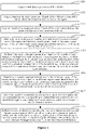
- Figure 1 is a schematic flow chart of a method for optimizing and designing low in-vehicle noise according to an embodiment of the present disclosure. As shown in Figure 1 , the method includes steps S101 to S104 as follows.
- step S101 acquire sound source distribution characteristics corresponding to different regions of a to-be-designed vehicle and sound source devices respectively, and establish an in-vehicle noise simulation-prediction-analysis model based on the sound source distribution characteristics.
- step S101 the in-vehicle noise simulation-prediction-analysis model is established based on a statistical energy analysis theory and the sound source distribution characteristics corresponding to the different regions of the to-be-designed vehicle and the sound source devices.
- the different regions of the to-be designed vehicle include a floor, a side wall, a roof, an end wall, a passenger compartment side door, a driver's cab door, a window, a windshield, a front end of the driver's cab, and the like.
- the sound source devices include: a wheel and rail, an air conditioner, a traction converter, an auxiliary converter, a traction motor, an air compressor, a gear box, and other auxiliary devices.
- the sound source distribution characteristics are related to the different regions of the to-be-designed vehicle and positions of the sound source devices.
- the different regions of the to-be designed vehicle correspond to different sound source distribution characteristics
- the sound source devices at different positions correspond to different sound source distribution characteristics.
- the sound source distribution characteristics corresponding to the different regions of to-be-designed vehicle and the sound source devices may be determined.
- An example is provided to facilitate understanding a process of acquiring sound source distribution characteristics corresponding to different regions of a to-be-designed vehicle and sound source devices. For example, in a case where a sound source device is an air conditioner mounted on a side wall, a sound source distribution characteristic corresponding to such case may be obtained.
- step S102 perform noise prediction based on the in-vehicle noise simulation-prediction-analysis model iteratively until a predicted noise value L psi satisfying a minimum total cost for in-vehicle noise reduction is outputted and a difference between the predicted noise value L psi and a target noise value L pi is less than a preset difference.
- the noise prediction is performed by taking a sound transmission loss TL i of each of the different regions of the to-be-designed vehicle and a sound power L wj of each of the sound source devices as an input to the in-vehicle noise simulation-prediction-analysis model, the noise prediction starts with an input of initial sound transmission losses and initial sound powers and iterates under a constraint on a total cost for in-vehicle noise reduction.
- step S102 the constraint on a total cost for in-vehicle noise reduction is expressed as where L pi represents the target noise value, ⁇ TL i represents an increment of the sound transmission loss of each of the different regions of the to-be-designed vehicle, ⁇ L w represents a decrement of the sound power of each of the sound source devices, i ranges from 1 to M, where M represents a total number of the different regions of the to-be-designed vehicle and is a positive integer greater than 1, and j ranges from 1 to N, where N represents a total number of the sound source devices of the to-be-designed vehicle and is a positive integer greater than 1.
- the sound transmission losses TL i of the different regions include a sound transmission loss of any one or more of following regions of the vehicle: a floor, a side wall, a roof, an end wall, a passenger compartment side door, a driver's cab door, a window, a windshield, and a front end of the driver's cab.
- the sound powers L wj of the sound source devices include a sound power of any one or more of a wheel and rail, an air conditioner, a traction converter, an auxiliary converter, a traction motor, an air compressor, and a gear box.
- the initial sound transmission losses are determined based on initial design parameters of the different regions of the vehicle.
- the initial sound powers are determined based on initial design parameters of the sound sources devices.
- the preset difference may be equal to 3, 5 or the like, which is set based on an actual situation and is not specifically limited herein.
- step S103 acquire a design parameter of each of the different regions of the to-be-designed vehicle and a design parameter of each of the sound source devices which are used to obtain the predicted noise value L psi .
- the predicted noise value L psi is obtained when the minimum total cost for in-vehicle noise reduction is satisfied, and the design parameter of each of the different regions of the to-be-designed vehicle and the design parameter of each of the sound source devices used to obtain the predicted noise value L psi are acquired.
- the design parameters of the different regions of the to-be-designed vehicle used to obtain the predicted noise value L psi include: a thickness and material of the floor of the vehicle, a thickness and material of the side wall of the vehicle, a thickness and material of the roof of the vehicle, a thickness and material of the end wall of the vehicle, a thickness and material of the passenger compartment side door of the vehicle, a thickness and material of the driver's cab door of the vehicle, a thickness and material of the window of the vehicle, a thickness and material of the windshield of the vehicle, and a thickness and material of the front end of the driver's cab of the vehicle.
- the design parameters of the sound source devices of the to-be-designed vehicle used to obtain the predicted noise value L psi include: the sound power of the wheel and rail of the vehicle, the sound power of the air conditioner of the vehicle, the sound power of the traction converter of the vehicle, the sound power of the auxiliary converter of the vehicle, the sound power of the traction motor of the vehicle, the sound power of the air compressor of the vehicle, and the sound power of the gear box of the vehicle.
- step S104 design a vehicle based on the design parameter of each of the different regions of the to-be-designed vehicle and the design parameter of each of the sound source devices.
- the vehicle is designed based on the design parameter of each of the different regions of the to-be-designed vehicle and the design parameter of each of the sound source devices, so as to optimize the in-vehicle noise with the minimum total cost for in-vehicle noise reduction.
- the vehicle is designed based on the following design parameters of the to-be-designed vehicle: the thickness and material of regions of the vehicle such as the floor, the side wall, the roof, the end wall, the passenger compartment side door, the driver's cab door, the window, the windshield and the front end of the driver's cab; and the sound power of auxiliary devices of the vehicle such as the wheel and rail, the air conditioner, the traction converter, the auxiliary converter, the traction motor, the air compressor, and the gear box.
- the thickness and material of regions of the vehicle such as the floor, the side wall, the roof, the end wall, the passenger compartment side door, the driver's cab door, the window, the windshield and the front end of the driver's cab
- the sound power of auxiliary devices of the vehicle such as the wheel and rail, the air conditioner, the traction converter, the auxiliary converter, the traction motor, the air compressor, and the gear box.
- noise prediction is performed based on the in-vehicle noise simulation-prediction-analysis model iteratively to obtain a predicted noise value L psi that has no deviation and takes a minimum total cost for in-vehicle noise reduction, so that the method for optimizing and designing low in-vehicle noise has a short period, low cost, and is not prone to deviation.
- the method does not require any subjective experience from a designer for vehicle design, and thereby has no subjectivity.
- step S102 involves a process of performing the noise prediction based on the in-vehicle noise simulation-prediction-analysis model iteratively with starting with the input of the initial sound transmission losses and the initial sound powers and being under the constraint on a total cost for in-vehicle noise reduction.
- Figure 2 shows a schematic flow chart of the process of performing noise prediction based on the in-vehicle noise simulation-prediction-analysis model iteratively. As shown in Figure 2 , the process includes steps S201 to S208 as follows.
- step S201 acquire initial design parameters of the vehicle.
- the initial design parameters of the vehicle include a design parameter of each of the different regions of the vehicle and a design parameter of each of the sound source devices.
- the design parameters of the different regions of the vehicle include a thickness and material of the following regions of the vehicle: a floor, a side wall, a roof, an end wall, a passenger compartment side door, a driver's cab door, a window, a windshield, a front end of the driver's cab.
- the design parameters of the sound source devices include a sound power of the following sound source devices of the vehicle: a wheel and rail, an air conditioner, a traction converter, an auxiliary converter, a traction motor, an air compressor, a gear box.
- step S202 acquire, based on the design parameter of each of the different regions of the vehicle, the initial sound transmission loss of the region.
- step S202 the initial sound transmission loss depends on an initial design parameter of the different regions of the vehicle.
- An example is provided to facilitate understanding the process of acquiring the initial sound transmission loss of each of the regions based on the design parameter of the region of the vehicle in step S202. For example, it is determined, based on the thickness and material of a side wall of the vehicle, that the initial sound transmission loss of the side wall of the vehicle is 20db; and it is determined, based on the thickness and material of a roof of the vehicle, that the initial sound transmission loss of the roof of the vehicle is 35db.
- step S203 acquire, based on the design parameter of each of the sound source devices, the initial sound power of the sound source device.
- the initial sound power depends on an initial design parameter of the sound source device.
- An example is provided to facilitate understanding the process of acquiring the initial sound power of each of the sound source devices based on the design parameter of the sound source device in step S203. For example, it is determined that the initial sound power of the sound source device being a wheel and rail is 110db based on the sound source device being a wheel and rail, and it is determined that the initial sound transmission loss of the sound source device being an air conditioner is 76db based on the sound source device being an air conditioner.
- step S204 perform the noise prediction by inputting the initial sound transmission loss of each of the regions and the initial sound power of each of the sound source devices to the in-vehicle noise simulation-prediction-analysis model, to obtain an initial predicted noise value.
- the predicted noise value that satisfies the minimum total cost for in-vehicle noise reduction is required to be outputted, it is required to input the initial sound transmission loss of each of the regions and the initial sound power of each of the sound source devices to the in-vehicle noise simulation-prediction-analysis model for noise prediction to obtain an initial predicted noise value, and then the noise prediction is performed based on the in-vehicle noise simulation-prediction-analysis model iteratively with starting with the initial sound transmission losses and the initial sound powers, until the predicted noise value L psi that satisfies the minimum total cost for in-vehicle noise reduction is outputted.
- step S205 perform calculation under the constraint on a total cost for in-vehicle noise reduction and based on a multivariate non-linear programming theory, to obtain the minimum total cost for in-vehicle noise reduction, the increment ⁇ TL i of the sound transmission loss of each of the different regions under the minimum total cost for in-vehicle noise reduction, and the decrement ⁇ L w of the sound power of each of the sound source devices under the minimum total cost for in-vehicle noise reduction.
- f represents the total cost for in-vehicle noise reduction
- k i represents a cost corresponding to the increment ⁇ TL i of the sound transmission loss
- k j represents a cost corresponding to the decrement ⁇ L w of the sound power.
- the minimum total cost for in-vehicle noise reduction indicates an optimized situation regarding the total cost for in-vehicle noise reduction.
- step S206 determine an acoustic requirement indicated by the increment of the sound transmission loss of each of the different regions under the minimum total cost for in-vehicle noise reduction and an acoustic requirement indicated by the decrement of the sound power of each of the sound source devices under the minimum total cost for in-vehicle noise reduction.
- step S206 a first acoustic requirement of each of the different regions indicated by the increment ⁇ TL i of the sound transmission loss of the region under the minimum total cost is acquired, and a second acoustic requirement of each of the sound source devices indicated by the decrement ⁇ L w of the sound power of the sound source device under the minimum total cost is required.
- the first acoustic requirement characterizes the sound transmission loss of the region under the minimum cost for in-vehicle noise reduction.
- the second acoustic requirement characterizes the sound power of the sound source device under the minimum cost for in-vehicle noise reduction.
- step S207 determine, based on the acoustic requirements, a design parameter and a new sound transmission loss corresponding to a noise reduction scheme for each of the different regions, and a design parameter and a new sound power of each of the sound source devices.
- step S207 a parameter of material for constructing each of the different regions is acquired based on the noise reduction scheme for the region corresponding to the first acoustic requirement, and the new sound transmission loss corresponding to the region is acquired based on the parameter of material.
- An adjusting parameter of each of the sound source devices is acquired based on the noise reduction scheme for the sound source device corresponding to the second acoustic requirement, and the new sound power corresponding to the sound source device is acquired based on the adjusting parameter.
- An example is provided to facilitate understanding the process of acquiring a parameter of material for constructing each of the different regions based on the noise reduction scheme for the region corresponding to the first acoustic requirement and acquiring the new sound transmission loss corresponding to the region based on the parameter of material in step S207.
- the noise reduction scheme is to apply carbon fiber cotton material with a thickness of 3cm onto the floor based on the sound transmission loss being 42db, and a value of the new sound transmission loss of the floor is 35db based on the carbon fiber cotton material with a thickness of 3cm.
- An example is provided to facilitate understanding the process of acquiring an adjusting parameter of each of the sound source devices based on the noise reduction scheme for the sound source device corresponding to the second acoustic requirement, and acquiring the new sound power corresponding to the sound source device based on the adjusting parameter in step S207.
- step S208 perform the noise prediction by inputting the new sound transmission losses and the new sound powers to the in-vehicle noise simulation-prediction-analysis model, until the predicted noise value L psi satisfying the minimum total cost for in-vehicle noise reduction is outputted and the difference between the predicted noise value L psi and the target noise value L pi is less than the preset difference.
- An example is provided as follows to facilitate understanding of the process of perform the noise prediction by inputting the new sound transmission losses and the new sound powers to the in-vehicle noise simulation-prediction-analysis model, until the predicted noise value L psi satisfying the minimum total cost for in-vehicle noise reduction is outputted.
- the new sound transmission loss and the new sound power are inputted to the in-vehicle noise simulation-prediction-analysis model for noise prediction, if the difference between the predicted noise value L psi and the target noise value L pi is greater than or equal to the preset difference, a second process of acquiring a new sound transmission loss and a new sound power is performed.
- a parameter of material for constructing each of the different regions is acquired based on the noise reduction scheme for the region corresponding to the first acoustic requirement, and a new sound transmission loss corresponding to the region is acquired based on the parameter of material; and an adjusting parameter of each of the sound source devices is acquired based on the noise reduction scheme for the sound source device corresponding to the second acoustic requirement, and a new sound power corresponding to the sound source device is acquired based on the adjusting parameter.
- the new sound transmission loss and new sound power acquired in the second process are inputted to the in-vehicle noise simulation-prediction-analysis model for noise prediction.
- the process is performed repeatedly until the difference between the outputted predicted noise value L psi and the target noise value L pi is less than the preset difference, then this predicted noise value L psi satisfying the minimum total cost for in-vehicle noise reduction is outputted.
- an in-vehicle noise reduction scheme is optimized based on a cost consideration by using the non-linear programming theory, so as to make the noise reduction scheme efficient enough.
- acoustic requirements of different regions of a vehicle are arranged systematically, reasonably and effectively, so that the designed vehicle has a better noise reduction effect.
- a vehicle is designed based on the design parameter of each of the different regions of the to-be-designed vehicle and the design parameter of each of the sound source devices.
- Figure 3 is a schematic diagram showing a design of a vehicle.
- the design parameters of different regions of the to-be-designed vehicle include: a thickness and material of a side wall, a thickness and material of a roof, a thickness and material of a passenger compartment side door, a thickness and material of a driver's cab door, a thickness and material of a window, a thickness and material of a windshield, a thickness and material of a front end of the driver's cab, and a thickness and material of other regions.
- the design parameters of the sound source devices of the to-be-designed vehicle include: a sound power of a wheel and rail of the vehicle, a sound power of an air conditioner of the vehicle, a sound power of a traction converter of the vehicle, a sound power of an auxiliary converter of the vehicle, a sound power of a traction motor of the vehicle, a sound power of an air compressor of the vehicle, a sound power of a gear box of the vehicle, and a sound power of other auxiliary devices.
- a vehicle is designed based on the design parameters of different regions of the to-be-designed vehicle and the design parameters of the sound source devices of the to-be-designed vehicle, so as to make a noise reduction scheme efficient enough.
- the vehicle is designed by using the design parameters of different regions of the to-be-designed vehicle and the design parameters of the sound source devices of the to-be-designed vehicle in a reasonable and effective manner, without requirement for any subjective experience from a designer, thereby having no subjectivity.
- the system for optimizing and designing low in-vehicle noise mainly includes an establishing unit 401, an output unit 402, an acquiring unit 403, and a design unit 404.
- the establishing unit 401 is configured to acquire sound source distribution characteristics corresponding to different regions of a to-be-designed vehicle and sound source devices respectively, and establish an in-vehicle noise simulation-prediction-analysis model based on the sound source distribution characteristics.
- the in-vehicle noise simulation-prediction-analysis model is established based on a statistical energy analysis theory and the sound source distribution characteristics corresponding to the different regions of the to-be-designed vehicle and the sound source devices.
- the different regions of the to-be designed vehicle mentioned in the description of the establishing unit 401 include a floor, a side wall, a roof, an end wall, a passenger compartment side door, a driver's cab door, a window, a windshield, a front end of the driver's cab, and the like.
- the sound source devices mentioned in the description of the establishing unit 401 include: a wheel and rail, an air conditioner, a traction converter, an auxiliary converter, a traction motor, an air compressor, a gear box, and other auxiliary devices.
- the sound source distribution characteristics are related to the different regions of the to-be-designed vehicle and positions of the sound source devices.
- the different regions of the to-be designed vehicle correspond to different sound source distribution characteristics
- the sound source devices at different positions correspond to different sound source distribution characteristics.
- the output unit 402 is configured to perform noise prediction based on the in-vehicle noise simulation-prediction-analysis model iteratively until a predicted noise value L psi satisfying a minimum total cost for in-vehicle noise reduction is outputted and a difference between the predicted noise value L psi and a target noise value L pi is less than a preset difference, where the noise prediction is performed by taking a sound transmission loss TL i of each of the different regions of the to-be-designed vehicle and a sound power L wj of each of the sound source devices as an input to the in-vehicle noise simulation-prediction-analysis model, the noise prediction starts with an input of initial sound transmission losses and initial sound powers and iterates under a constraint on a total cost for in-vehicle noise reduction.
- L pi represents the target noise value
- ⁇ TL i represents an increment of the sound transmission loss of each of the different regions of the to-be-designed vehicle
- ⁇ L w represents a decrement of the sound power of each of the sound source devices
- i ranges from 1 to M
- M represents a total number of the different regions of the to-be-designed vehicle and is a positive integer greater than
- j ranges from 1 to N, where N represents a total number of the sound source devices of the to-be-designed vehicle and is a positive integer greater than 1.
- the sound transmission losses TL i of the different regions include a sound transmission loss of any one or more of following regions of the vehicle: a floor, a side wall, a roof, an end wall, a passenger compartment side door, a driver's cab door, a window, a windshield, and a front end of the driver's cab.
- the sound powers L wj of the sound source devices include a sound power of any one or more of a wheel and rail, an air conditioner, a traction converter, an auxiliary converter, a traction motor, an air compressor, and a gear box.
- the output unit 402 includes a first acquiring module, a second acquiring module, a third acquiring module, a predicting module, a calculating module, a determining module, a fourth acquiring module, a fifth acquiring module and an output module.
- the first acquiring module is configured to acquire initial design parameters of the vehicle.
- the initial design parameters of the to-be-designed vehicle include a design parameter of each of the different regions of the vehicle and a design parameter of each of the sound source devices.
- the second acquiring module is configured to acquire, based on the design parameter of each of the different regions of the vehicle, the initial sound transmission loss of the region.
- the third acquiring module is configured to acquire, based on the design parameter of each of the sound source devices, the initial sound power of the sound source device.
- the predicting module is configured to perform the noise prediction by inputting the initial sound transmission loss of each of the regions and the initial sound power of each of the sound source devices to the in-vehicle noise simulation-prediction-analysis model, to obtain an initial predicted noise value.
- the calculating module is configured to perform calculation under the constraint on a total cost for in-vehicle noise reduction and based on a multivariate non-linear programming theory, to obtain the minimum total cost for in-vehicle noise reduction, the increment ⁇ TL i of the sound transmission loss of each of the different regions under the minimum total cost for in-vehicle noise reduction, and the decrement ⁇ L w of the sound power of each of the sound source devices under the minimum total cost for in-vehicle noise reduction.
- the calculating module includes a calculating sub-module and a determining sub-module.
- the determining sub-module is configured to determine the increment ⁇ TL i of the sound transmission loss of each of the different regions under the minimum total cost for in-vehicle noise reduction, and the decrement ⁇ L w of the sound power of each of the sound source devices under the minimum total cost for in-vehicle noise reduction.
- the first determining module is configured to determine an acoustic requirement indicated by the increment ⁇ TL i of the sound transmission loss of each of the different regions under the minimum total cost for in-vehicle noise reduction and an acoustic requirement indicated by the decrement ⁇ L w of the sound power of each of the sound source devices under the minimum total cost for in-vehicle noise reduction.
- the second determining module is configured to determine, based on the acoustic requirements, a design parameter and a new sound transmission loss corresponding to a noise reduction scheme for each of the different regions, and a design parameter and a new sound power of each of the sound source devices.
- the output module is configured to perform the noise prediction by inputting the new sound transmission losses and the new sound powers to the in-vehicle noise simulation-prediction-analysis model, until the predicted noise value L psi satisfying the minimum total cost for in-vehicle noise reduction is outputted and the difference between the predicted noise value L psi and the target noise value L pi is less than the preset difference.
- the acquiring unit 403 is configured to acquire a design parameter of each of the different regions of the to-be-designed vehicle and a design parameter of each of the sound source devices which are used to obtain the predicted noise value L psi .
- the predicted noise value L psi is obtained when the minimum total cost for in-vehicle noise reduction is satisfied, and the design parameter of each of the different regions of the to-be-designed vehicle and the design parameter of each of the sound source devices used to obtain the predicted noise value L psi are acquired.
- the design parameters of the different regions of the to-be-designed vehicle used to obtain the predicted noise value L psi include: a thickness and material of the floor of the vehicle, a thickness and material of the side wall of the vehicle, a thickness and material of the roof of the vehicle, a thickness and material of the end wall of the vehicle, a thickness and material of the passenger compartment side door of the vehicle, a thickness and material of the driver's cab door of the vehicle, a thickness and material of the window of the vehicle, a thickness and material of the windshield of the vehicle, and a thickness and material of the front end of the driver's cab of the vehicle.
- the design parameters of the sound source devices of the to-be-designed vehicle used to obtain the predicted noise value L psi include: the sound power of the wheel and rail of the vehicle, the sound power of the air conditioner of the vehicle, the sound power of the traction converter of the vehicle, the sound power of the auxiliary converter of the vehicle, the sound power of the traction motor of the vehicle, the sound power of the air compressor of the vehicle, and the sound power of the gear box of the vehicle.
- the design unit 404 is configured to design a vehicle based on the design parameter of each of the different regions of the to-be-designed vehicle and the design parameter of each of the sound source devices.
- the vehicle is designed based on the design parameter of each of the different regions of the to-be-designed vehicle and the design parameter of each of the sound source devices, such that the in-vehicle noise is optimized under the minimum total cost for in-vehicle noise reduction.
- a system for optimizing and designing low in-vehicle noise is provided according to the embodiments of the present disclosure, in which noise prediction is performed iteratively based on an in-vehicle noise simulation-prediction-analysis model to obtain a predicted noise value L psi that has no deviation and takes a minimum total cost for in-vehicle noise reduction.
- the system for optimizing and designing low in-vehicle noise according to the present disclosure has a short period, low cost, and is not prone to deviation.
- the system does not require any subjective experience from a designer when designing a vehicle, and thereby has no subjectivity.
Landscapes
- Engineering & Computer Science (AREA)
- Physics & Mathematics (AREA)
- Geometry (AREA)
- Theoretical Computer Science (AREA)
- General Physics & Mathematics (AREA)
- Computer Hardware Design (AREA)
- General Engineering & Computer Science (AREA)
- Evolutionary Computation (AREA)
- Aviation & Aerospace Engineering (AREA)
- Pure & Applied Mathematics (AREA)
- Mathematical Optimization (AREA)
- Mathematical Analysis (AREA)
- Computational Mathematics (AREA)
- Automation & Control Theory (AREA)
- Measurement Of Mechanical Vibrations Or Ultrasonic Waves (AREA)
Applications Claiming Priority (2)
| Application Number | Priority Date | Filing Date | Title |
|---|---|---|---|
| CN202011028783.6A CN112163274B (zh) | 2020-09-25 | 2020-09-25 | 一种车内低噪声优化设计方法及系统 |
| PCT/CN2020/118669 WO2022061944A1 (fr) | 2020-09-25 | 2020-09-29 | Procédé de conception d'optimisation d'atténuation de bruits d'intérieur de véhicule, et système |
Publications (2)
| Publication Number | Publication Date |
|---|---|
| EP4002188A1 true EP4002188A1 (fr) | 2022-05-25 |
| EP4002188A4 EP4002188A4 (fr) | 2022-08-31 |
Family
ID=73862987
Family Applications (1)
| Application Number | Title | Priority Date | Filing Date |
|---|---|---|---|
| EP20934896.0A Pending EP4002188A4 (fr) | 2020-09-25 | 2020-09-29 | Procédé de conception d'optimisation d'atténuation de bruits d'intérieur de véhicule, et système |
Country Status (3)
| Country | Link |
|---|---|
| EP (1) | EP4002188A4 (fr) |
| CN (1) | CN112163274B (fr) |
| WO (1) | WO2022061944A1 (fr) |
Families Citing this family (11)
| Publication number | Priority date | Publication date | Assignee | Title |
|---|---|---|---|---|
| CN112818539B (zh) * | 2021-01-29 | 2022-11-15 | 中车青岛四方机车车辆股份有限公司 | 一种窗户的隔声设计方法及隔声设计系统 |
| CN113255060B (zh) * | 2021-05-27 | 2022-04-15 | 东风汽车集团股份有限公司 | 车辆隔音性能分析方法、系统及介质 |
| CN113358211B (zh) * | 2021-05-28 | 2024-04-30 | 江苏徐工国重实验室科技有限公司 | 噪声测试方法及装置 |
| CN113673042B (zh) * | 2021-09-06 | 2023-12-12 | 江南造船(集团)有限责任公司 | 基于声环境仿真的船舶降噪系统设计方法、系统、介质及终端 |
| CN114000938B (zh) * | 2021-11-12 | 2024-04-19 | 无锡威孚力达催化净化器有限责任公司 | 调音阀开度优化方法 |
| CN114280159A (zh) * | 2021-12-24 | 2022-04-05 | 智己汽车科技有限公司 | 一种数字化的汽车声学零部件仿真方法、系统和设备 |
| CN114925446A (zh) * | 2022-05-05 | 2022-08-19 | 北京汽车股份有限公司 | 一种汽车前围内隔音垫的设计方法及隔音垫 |
| CN115081339B (zh) * | 2022-07-18 | 2025-03-18 | 安徽理工大学 | 一种基于可靠度换流变压器声功率级反推方法 |
| CN116305599B (zh) * | 2022-09-08 | 2026-02-27 | 极光湾(义乌)发动机有限公司 | 一种发动机曲轴系统噪声识别和优化方法 |
| CN115795835B (zh) * | 2022-11-18 | 2025-12-19 | 国网江苏省电力有限公司 | 一种声学优化材料选取方法、装置、电子设备及存储介质 |
| CN121706215A (zh) * | 2026-02-10 | 2026-03-20 | 中铁建工集团有限公司 | 基于多参数反馈的机房降噪方案优化配置系统 |
Family Cites Families (10)
| Publication number | Priority date | Publication date | Assignee | Title |
|---|---|---|---|---|
| KR101025163B1 (ko) * | 2008-11-14 | 2011-03-31 | 한양대학교 산학협력단 | 진동 및 소음 전달경로 해석 시스템과 진동 및 소음 전달경로 해석 방법 |
| CN103971908B (zh) * | 2014-05-06 | 2016-03-09 | 国家电网公司 | 一种变压器噪声抑制方法 |
| CN105590003A (zh) * | 2016-01-05 | 2016-05-18 | 浙江大学 | 一种高速列车车内噪声分析预测方法 |
| AU2017286519B2 (en) * | 2016-06-13 | 2020-05-07 | Med-El Elektromedizinische Geraete Gmbh | Recursive noise power estimation with noise model adaptation |
| CN107745721B (zh) * | 2017-10-16 | 2019-08-27 | 中车唐山机车车辆有限公司 | 动车组低噪声设计方法 |
| CN107862141B (zh) * | 2017-11-10 | 2020-08-04 | 西南交通大学 | 一种轨道车辆低噪声正向设计方法 |
| CN110875031B (zh) * | 2018-08-30 | 2023-10-03 | 株洲中车时代电气股份有限公司 | 一种轨道交通变流器噪声的预测方法 |
| CN109323872A (zh) * | 2018-10-31 | 2019-02-12 | 中车株洲电力机车有限公司 | 一种轨道交通车辆的整车噪声指标分解方法、装置及系统 |
| EP3663943A1 (fr) * | 2018-12-07 | 2020-06-10 | Hitachi, Ltd. | Procédé et système de conception de l'intérieur d' un véhicule ferroviaire basés sur la simulation du niveau de bruit acoustique |
| CN110502844B (zh) * | 2019-08-27 | 2023-04-07 | 中车株洲电力机车有限公司 | 一种轨道交通车辆噪声数字样机的优化设计方法 |
-
2020
- 2020-09-25 CN CN202011028783.6A patent/CN112163274B/zh active Active
- 2020-09-29 WO PCT/CN2020/118669 patent/WO2022061944A1/fr not_active Ceased
- 2020-09-29 EP EP20934896.0A patent/EP4002188A4/fr active Pending
Also Published As
| Publication number | Publication date |
|---|---|
| EP4002188A4 (fr) | 2022-08-31 |
| WO2022061944A1 (fr) | 2022-03-31 |
| CN112163274A (zh) | 2021-01-01 |
| CN112163274B (zh) | 2021-08-06 |
Similar Documents
| Publication | Publication Date | Title |
|---|---|---|
| EP4002188A1 (fr) | Procédé de conception d'optimisation d'atténuation de bruits d'intérieur de véhicule, et système | |
| CN110793621B (zh) | 纯电动汽车动力系统阶次噪声测评方法及系统 | |
| US8880380B2 (en) | Crashworthiness design methodology using a hybrid cellular automata algorithm for the synthesis of topologies for structures subject to nonlinear transient loading | |
| CN113591228B (zh) | 一种噪声传递路径分析及优化方法 | |
| CN109323872A (zh) | 一种轨道交通车辆的整车噪声指标分解方法、装置及系统 | |
| US20070246209A1 (en) | Control method of air-conditioner for hybrid engine vehicle | |
| CN106446423B (zh) | 车身结构优化设计方法及装置 | |
| ATE269235T1 (de) | Verstärkungsträger für fahrzeugtür und verfahren zur herstellung | |
| CN109080503A (zh) | 车速控制方法、系统、可读存储介质及电动汽车 | |
| DE102011000450A1 (de) | Trägerstruktur für ein Fahrzeug sowie Verfahren zur Herstellung einer Trägerstruktur für ein Fahrzeug | |
| CN111527019A (zh) | 运行曲线制作装置、运行辅助装置以及运行控制装置 | |
| CN105196833A (zh) | 一种车载节能自动空调控制方法及装置 | |
| DE102010009611A1 (de) | Reisemobil sowie Schottbauteil und Stützgerüst für ein Reisemobil | |
| DE102013205223A1 (de) | Verfahren zur Steuerung einer Klimaanlage eines Kraftfahrzeugs | |
| CN101010192B (zh) | 结合在车辆的玻璃窗和车体之间的声阻尼条 | |
| Li et al. | A modelling approach for noise transmission through extruded panels in railway vehicles | |
| CN116611337A (zh) | 一种车内风噪仿真方法、系统、电子设备及存储介质 | |
| DE102020205923A1 (de) | Steuervorrichtung und Verfahren zur Ansteuerung eines elektrischen Antriebssystems sowie elektrisches Antriebssystem | |
| KR101292682B1 (ko) | 이동 차량 객실안의 음향 쾌적성을 최적화하기 위한 방법 | |
| Zhang | Research on the Influence of Door and Window Sealing on Interior Wind Noise Based on Statistical Energy Analysis | |
| JP2001171349A (ja) | パネル構造体の補強材配設方法 | |
| US20210039566A1 (en) | Vehicles Including Shaped Reinforcement Brackets for a Headliner | |
| DE102018116439A1 (de) | System und Verfahren für ein aktives Thermomanagement | |
| CN204340612U (zh) | 车门和车辆 | |
| Deng et al. | Study of boundary conditions and parameters effects on TL of the automobile door sealing system |
Legal Events
| Date | Code | Title | Description |
|---|---|---|---|
| STAA | Information on the status of an ep patent application or granted ep patent |
Free format text: STATUS: UNKNOWN |
|
| STAA | Information on the status of an ep patent application or granted ep patent |
Free format text: STATUS: THE INTERNATIONAL PUBLICATION HAS BEEN MADE |
|
| PUAI | Public reference made under article 153(3) epc to a published international application that has entered the european phase |
Free format text: ORIGINAL CODE: 0009012 |
|
| STAA | Information on the status of an ep patent application or granted ep patent |
Free format text: STATUS: REQUEST FOR EXAMINATION WAS MADE |
|
| 17P | Request for examination filed |
Effective date: 20211119 |
|
| AK | Designated contracting states |
Kind code of ref document: A1 Designated state(s): AL AT BE BG CH CY CZ DE DK EE ES FI FR GB GR HR HU IE IS IT LI LT LU LV MC MK MT NL NO PL PT RO RS SE SI SK SM TR |
|
| A4 | Supplementary search report drawn up and despatched |
Effective date: 20220803 |
|
| RIC1 | Information provided on ipc code assigned before grant |
Ipc: G06F 119/10 20200101ALI20220728BHEP Ipc: G06F 30/20 20200101ALI20220728BHEP Ipc: G06F 30/15 20200101AFI20220728BHEP |
|
| DAV | Request for validation of the european patent (deleted) | ||
| DAX | Request for extension of the european patent (deleted) | ||
| STAA | Information on the status of an ep patent application or granted ep patent |
Free format text: STATUS: EXAMINATION IS IN PROGRESS |
|
| 17Q | First examination report despatched |
Effective date: 20240528 |