EP4002390A1 - Système de blocage permettant de bloquer les solides irradiés ou à irradier - Google Patents
Système de blocage permettant de bloquer les solides irradiés ou à irradier Download PDFInfo
- Publication number
- EP4002390A1 EP4002390A1 EP20208937.1A EP20208937A EP4002390A1 EP 4002390 A1 EP4002390 A1 EP 4002390A1 EP 20208937 A EP20208937 A EP 20208937A EP 4002390 A1 EP4002390 A1 EP 4002390A1
- Authority
- EP
- European Patent Office
- Prior art keywords
- shut
- open position
- closed position
- actuating element
- base body
- Prior art date
- Legal status (The legal status is an assumption and is not a legal conclusion. Google has not performed a legal analysis and makes no representation as to the accuracy of the status listed.)
- Withdrawn
Links
- 239000007787 solid Substances 0.000 title claims abstract description 49
- 239000003380 propellant Substances 0.000 claims abstract description 32
- 230000004913 activation Effects 0.000 claims abstract description 27
- 239000012530 fluid Substances 0.000 claims abstract description 18
- 238000007789 sealing Methods 0.000 claims description 12
- 230000004907 flux Effects 0.000 claims description 8
- 238000009826 distribution Methods 0.000 claims description 7
- 238000006073 displacement reaction Methods 0.000 claims description 3
- 239000007789 gas Substances 0.000 description 33
- 238000005259 measurement Methods 0.000 description 13
- 230000000903 blocking effect Effects 0.000 description 10
- IJGRMHOSHXDMSA-UHFFFAOYSA-N Atomic nitrogen Chemical compound N#N IJGRMHOSHXDMSA-UHFFFAOYSA-N 0.000 description 8
- 230000005855 radiation Effects 0.000 description 7
- 229910000831 Steel Inorganic materials 0.000 description 4
- 238000010586 diagram Methods 0.000 description 4
- 230000000694 effects Effects 0.000 description 4
- 238000004519 manufacturing process Methods 0.000 description 4
- 230000002285 radioactive effect Effects 0.000 description 4
- 239000010959 steel Substances 0.000 description 4
- 238000000605 extraction Methods 0.000 description 3
- 229910052757 nitrogen Inorganic materials 0.000 description 3
- 229910052720 vanadium Inorganic materials 0.000 description 3
- LEONUFNNVUYDNQ-UHFFFAOYSA-N vanadium atom Chemical compound [V] LEONUFNNVUYDNQ-UHFFFAOYSA-N 0.000 description 3
- 230000008878 coupling Effects 0.000 description 2
- 238000010168 coupling process Methods 0.000 description 2
- 238000005859 coupling reaction Methods 0.000 description 2
- 238000013461 design Methods 0.000 description 2
- 230000009977 dual effect Effects 0.000 description 2
- 239000000446 fuel Substances 0.000 description 2
- 238000012986 modification Methods 0.000 description 2
- 230000004048 modification Effects 0.000 description 2
- 206010060862 Prostate cancer Diseases 0.000 description 1
- 208000000236 Prostatic Neoplasms Diseases 0.000 description 1
- 238000013459 approach Methods 0.000 description 1
- 230000008859 change Effects 0.000 description 1
- 230000006835 compression Effects 0.000 description 1
- 238000007906 compression Methods 0.000 description 1
- 238000013016 damping Methods 0.000 description 1
- 230000001419 dependent effect Effects 0.000 description 1
- 239000003814 drug Substances 0.000 description 1
- 238000005516 engineering process Methods 0.000 description 1
- 230000005484 gravity Effects 0.000 description 1
- 239000007788 liquid Substances 0.000 description 1
- 230000007257 malfunction Effects 0.000 description 1
- 239000000463 material Substances 0.000 description 1
- 238000000034 method Methods 0.000 description 1
- 238000009206 nuclear medicine Methods 0.000 description 1
- 230000035699 permeability Effects 0.000 description 1
- 238000003825 pressing Methods 0.000 description 1
- 230000008569 process Effects 0.000 description 1
- 238000005070 sampling Methods 0.000 description 1
- 239000013589 supplement Substances 0.000 description 1
Images


Classifications
-
- G—PHYSICS
- G21—NUCLEAR PHYSICS; NUCLEAR ENGINEERING
- G21C—NUCLEAR REACTORS
- G21C19/00—Arrangements for treating, for handling, or for facilitating the handling of, fuel or other materials which are used within the reactor, e.g. within its pressure vessel
- G21C19/28—Arrangements for introducing fluent material into the reactor core; Arrangements for removing fluent material from the reactor core
-
- G—PHYSICS
- G21—NUCLEAR PHYSICS; NUCLEAR ENGINEERING
- G21C—NUCLEAR REACTORS
- G21C17/00—Monitoring; Testing ; Maintaining
- G21C17/10—Structural combination of fuel element, control rod, reactor core, or moderator structure with sensitive instruments, e.g. for measuring radioactivity, strain
- G21C17/108—Measuring reactor flux
-
- G—PHYSICS
- G01—MEASURING; TESTING
- G01T—MEASUREMENT OF NUCLEAR OR X-RADIATION
- G01T3/00—Measuring neutron radiation
-
- G—PHYSICS
- G21—NUCLEAR PHYSICS; NUCLEAR ENGINEERING
- G21C—NUCLEAR REACTORS
- G21C19/00—Arrangements for treating, for handling, or for facilitating the handling of, fuel or other materials which are used within the reactor, e.g. within its pressure vessel
- G21C19/20—Arrangements for introducing objects into the pressure vessel; Arrangements for handling objects within the pressure vessel; Arrangements for removing objects from the pressure vessel
-
- G—PHYSICS
- G21—NUCLEAR PHYSICS; NUCLEAR ENGINEERING
- G21C—NUCLEAR REACTORS
- G21C23/00—Adaptations of reactors to facilitate experimentation or irradiation
-
- G—PHYSICS
- G21—NUCLEAR PHYSICS; NUCLEAR ENGINEERING
- G21G—CONVERSION OF CHEMICAL ELEMENTS; RADIOACTIVE SOURCES
- G21G1/00—Arrangements for converting chemical elements by electromagnetic radiation, corpuscular radiation or particle bombardment, e.g. producing radioactive isotopes
- G21G1/02—Arrangements for converting chemical elements by electromagnetic radiation, corpuscular radiation or particle bombardment, e.g. producing radioactive isotopes in nuclear reactors
-
- Y—GENERAL TAGGING OF NEW TECHNOLOGICAL DEVELOPMENTS; GENERAL TAGGING OF CROSS-SECTIONAL TECHNOLOGIES SPANNING OVER SEVERAL SECTIONS OF THE IPC; TECHNICAL SUBJECTS COVERED BY FORMER USPC CROSS-REFERENCE ART COLLECTIONS [XRACs] AND DIGESTS
- Y02—TECHNOLOGIES OR APPLICATIONS FOR MITIGATION OR ADAPTATION AGAINST CLIMATE CHANGE
- Y02E—REDUCTION OF GREENHOUSE GAS [GHG] EMISSIONS, RELATED TO ENERGY GENERATION, TRANSMISSION OR DISTRIBUTION
- Y02E30/00—Energy generation of nuclear origin
- Y02E30/30—Nuclear fission reactors
Definitions
- the present invention relates to a shut-off device for stopping irradiated solids or solids to be irradiated in a line system which is used to transport the solids by means of a propellant fluid, in particular a propellant gas, into and out of a nuclear reactor.
- the shut-off device can be used in particular to stop balls of a ball measuring system that is used to measure the neutron flux distribution in a nuclear reactor.
- the shut-off device can be used to stop targets of a nuclide activation system, which is used to irradiate the targets in a nuclear reactor.
- bullet measurement systems In order to measure the neutron flux distribution in a nuclear reactor, for example in a nuclear power plant, bullet measurement systems are known, which are often also referred to as bullet measurement systems.
- the flux distribution determined by means of a ball measuring system is used, among other things, to regularly recalibrate the continuously measuring (but equipped with fewer measuring points) neutron measuring systems and to validate their signals.
- a ball measurement system usually comprises a number of tubes which protrude into the reactor core in a vertical direction at a number of points parallel to the fuel rods.
- steel balls containing vanadium are transported into the tubes via a pipe system and with the help of a propellant gas, where they remain lined up along the fuel rods for a few minutes and are activated by the neutrons. With the help of the propellant the balls are then transported via the line system to a measuring table outside the reactor. There, the activity of the steel balls is measured with radiation detectors.
- the individual spheres can each be assigned to a position in the reactor core and the radiation activity of the spheres can be used to draw conclusions about the neutron flux at the respective points in the reactor core.
- the line system usually has a large number of control valves. Similarly, control valves can be used to distribute the balls to different positions on the stage.
- the spheres When transported through the pipe system, the spheres each receive a high level of kinetic energy and must be stopped before they reach the measurement position, for example, or if no measurement is carried out and the spheres are brought into a parking position.
- emergency closing blocks are used, for example in the event of a leak in an instrumentation finger, to separate a line system section near the reactor from a line system section remote from the reactor.
- rotary valves and ball valve valves are used to stop the balls or to close the lines.
- the existing ball measuring system can also be used for the irradiation of nuclides.
- the resulting radionuclides are used in medicine, but also in other areas of technology.
- nuclide activation targets can be placed in the instrumentation fingers of a ball measuring system if no measurement is being carried out.
- the targets which can be spherical, oval or cylindrical or have any other shape, are injected into the instrumentation fingers arranged in the reactor core by means of a propellant gas through the line system of the ball measuring system in the same way as the measuring balls.
- the measuring balls are in a parking position. If a measurement becomes necessary, the targets have to be removed from the tubes in the reactor core and transported to a parking position via the line system.
- the targets each receive a high level of kinetic energy during transport through the pipe system and must be positioned at or in front of each other can be stopped after reaching the parking position or in the event of an emergency. It must also be possible to remove the targets from the system after a sufficient irradiation time and to replace them with new targets to be irradiated. Here, too, stopping processes are necessary in order to slow down the targets before they are transferred to a removal container. In the same way as for stopping the measuring balls, rotary valves and ball valve valves are also used for stopping the targets in the prior art.
- From the DE 10 2017 125 606 A1 are known to be rotationally rigidly connected ball valve valves for stopping and distributing measuring balls and targets.
- the ball valve valves can be adjusted together using a single drive shaft.
- shut-off device for stopping irradiated solids or solids to be irradiated in a line system, which is easy to manufacture and space-saving.
- a shut-off device is proposed, as specified in the claim.
- claims 12 and 13 specify two different uses for such a shut-off device.
- Advantageous embodiments are specified in the dependent claims.
- the actuating element can be brought from the open position into the closed position and from the closed position into the open position by means of displacement, ie by means of a translatory movement, relative to the at least one base body.
- shut-off device Since the actuating element for opening and closing the shut-off device is displaced and not rotated as in the prior art, there are many possibilities for not only making the shut-off device easier to manufacture, but also for designing and arranging it in a particularly space-saving manner. In particular, rounded surfaces are no longer mandatory.
- the continuous channel present in each base body is thus closed in each case, ie blocked for the solid bodies, or opened.
- the actuating element extends into the base body or bodies in such a way that it interrupts the channel or channels in its closed position or releases it in the open position.
- the channel or channels extend on both sides of the actuating element and, depending on the position, the actuating element forms a locking bar or creates a connection between the two channel parts that are present on both sides.
- the actuating element preferably has corresponding connecting channels.
- a channel means a line that is completely enclosed by material, ie the channel forms a completely enclosed opening for the solids to pass through.
- the irradiated or to be irradiated solids can be used in particular as part of a spherical measuring system for measuring the neutron flux distribution in the nuclear reactor.
- the solid bodies are preferably made of steel containing vanadium.
- the line system then forms, together with the balls, part of a ball measurement system (also known as a shot measurement system).
- the solid bodies that are irradiated or to be irradiated can also be nuclide activation targets, which are irradiated in the reactor core for medical purposes, for example.
- the line system then forms part of a nuclide activation system, which is preferably present and used in combination with a ball measuring system.
- the nuclide activation system can be retrofitted subsequently to supplement a ball measuring system.
- the solid bodies are preferably spheres. In principle, however, they can also have any other shape, with a cylindrical, pellet-like shape being particularly suitable.
- the solid bodies usually have an outside diameter of one millimeter to two millimeters. Accordingly, the lines of the line system also have an inside diameter of one millimeter to 2 millimeters.
- the inside diameter of the lines and the continuous channel of the at least one base body can be slightly larger than the outside diameter of the solid body, but no more than one and a half times the outside diameter of the solid body.
- the propellant fluid can be a liquid or, which is preferred, a gas.
- the propellant gas is preferably nitrogen (N 2 ).
- the propellant fluid is introduced into the line system in order to convey the solids through the line system by means of positive and negative pressure.
- the line system is in particular a piggable line system.
- the shut-off device has a plurality of such base bodies, each with a continuous channel. are advantageous the channels of all base bodies in the open position of the actuating element for the solids are continuous and closed in the closed position.
- the shut-off device is then preferably used to shut off several lines.
- By moving the actuating element, which as mentioned preferably forms a locking bar it is also possible in a very simple manner to close or open a plurality of channels for the solid bodies provided in each case in a base body.
- the base bodies are preferably arranged one behind the other and the actuating element extends through all the base bodies. As a result, the additional space requirement for further channels that are to be shut off by the shut-off device is minimal.
- the channels advantageously extend parallel to one another. If the base bodies are also all arranged one behind the other, the channels are then arranged in a common plane. Such an arrangement is not only particularly space-saving, but the channels can also be closed and opened very easily by moving a single actuating element for the solid bodies, in particular can be closed and opened at the same time.
- the shut-off device thus preferably has a plurality of base bodies, but only a single actuating element, which is used to close and open the channels of all base bodies.
- the several base bodies are arranged one behind the other and clamped between two clamping elements.
- End blocks or covers can be used as clamping elements, for example, which abut from opposite sides against a row of base bodies arranged in between and are connected to one another by means of one or more connecting elements such as in particular connecting screws.
- the clamping elements are preferably drawn towards one another by means of the connecting elements and thereby clamp the base bodies arranged between them against one another.
- the clamping elements thus serve to hold the base body and advantageously the shut-off device together as a whole.
- the connecting element or elements preferably extend through the base body.
- the base body or base bodies preferably each have a cuboid external shape. If there are several base bodies, they are preferably configured identically. This simplifies production.
- the shut-off device can be designed in such a way that the number of base bodies can be adjusted as required.
- the shut-off is this non-destructively disassembled, so that more Base bodies can be added or existing ones can be removed before the shut-off device is then reassembled.
- the shut-off device therefore preferably has a modular structure.
- the at least one base body preferably has a passage opening which intersects with the channel, in particular intersects at right angles, through which the actuating element extends in a displaceable manner. If there are several base bodies, all base bodies preferably have such a through opening intersecting with the channel.
- the control element then extends through the through-openings of all base bodies, so that all channels can be closed or opened by moving the control element for the solid bodies.
- the channel or channels are preferably open to the driving fluid in the closed position of the actuating element, that is to say blocked only for the solid bodies, but not for the driving fluid.
- the at least one base body and/or the actuating element preferably has a groove, in particular an annular groove, in order to enable a passage for the propellant fluid in the closed position as well. If the adjusting element extends through the at least one base body and there is a channel part on both sides of the adjusting element in the closed position, the groove preferably extends from the first channel part to the second channel part. In this way, the channel is in the closed position closed to the solids by the actuating element, but still permeable to the propellant fluid due to the groove.
- the shut-off unit can also be designed in such a way that the channels of the base bodies are closed both for the solid bodies and for the propellant fluid when the actuating element is in the closed position.
- the at least one base body and/or the actuating element can have a braking device for braking the solid bodies.
- the actuating element can have a further continuous or non-continuous opening or recess parallel to the continuous connection channel or channels, which extends parallel to the connection channel into the base body and into which a spiral or other spring is inserted to keep the solid bodies brake in the closed position of the actuating element.
- a damping element can also be present in order to dampen the deceleration of the solid bodies.
- the braking device can also be formed in that the above-mentioned grooves, in particular annular grooves, which are formed on the actuating element in order to form a passage for the driving fluid in the closed position, are omitted or only have small dimensions.
- the propellant fluid When a solid body approaches the actuating element that is in the closed position, the propellant fluid then forms a cushion, which decelerates the solid body.
- the actuating element In order to transport the solid bodies away from the shut-off device again with the aid of the propellant fluid, the actuating element could be pushed back into the open position, so that the propellant fluid can pass through the actuating element unhindered. Braking reduces the momentum of impact of the solid body on the actuating element, as a result of which the actuating element and the solid bodies are subjected to less wear.
- a seal is advantageously provided in order to seal the at least one base body in relation to the actuating element in such a way that neither in the open position nor in the closed position can gas escape between the base body and the actuating element and out of the channel to the outside.
- “Outside” here means the environment outside the shut-off device.
- shut-off device has a plurality of base bodies
- a sealing element is preferably arranged between adjacent base bodies in order to prevent gas from escaping between the base bodies, either in the open position or in the closed position.
- “outside” means the environment outside the shut-off device.
- the shut-off device preferably has a stop surface, which is used to stop the actuating element when it is moved into the open position, in order to thereby define the open position.
- a stop surface which is used to stop the actuating element when it is moved into the open position, in order to thereby define the open position.
- the shut-off device also has a drive, which for Adjusting the actuating element from the open position to the closed position and vice versa is used.
- the drive can in particular be an electric or hydraulic drive.
- the drive can be a rotary drive or a linear drive.
- the drive is a pneumatic drive, ie a drive that is based on compressed air or on another gas, such as in particular nitrogen, as the working medium.
- the shut-off device preferably has a drive piston which is attached to the actuating element and which can be moved in two opposite directions by means of gas pressure.
- the shut-off device preferably has a piston chamber in which the drive piston is arranged in a displaceable manner.
- the present invention also relates to the use of the shut-off device, as described above, as a stopping element for balls of a ball measuring system, which is used to measure the neutron flux distribution in a nuclear reactor.
- the shut-off device can then also be referred to as a ball stopper.
- the blocking device is advantageously used to stop the balls in the parking position.
- the blocking device can also be arranged between the parking position and a measuring point, in particular a measuring table, in order to stop the balls in the parking position and, if necessary, to let them through to the measuring point.
- the present invention relates to the use of the shut-off device, as described above, as a stopping element for targets of a nuclide activation system, which serves to irradiate the targets in a nuclear reactor.
- the blocking device can then also be referred to as a target stopper or, if the targets are in the form of balls, as a ball stopper.
- the blocking device advantageously serves to stop the target in the parking position.
- the blocking device can also be arranged between the parking position and a removal point where the sufficiently irradiated targets can be removed from the nuclide activation system in order to stop the targets in the parking position and, if necessary, to let them through to the removal point.
- a connection box can be arranged between the shut-off device and the extraction point, which preferably, depending on which lines are connected, serves to forward the targets to the extraction point or to introduce or discharge propellant fluid into/from the nuclide activation system.
- shut-off device can be used in other embodiments and with a corresponding design, for example, as an emergency closing device.
- the emergency closing device can be used, for example, to separate a line system section near the reactor from a line system section remote from the reactor if a leak occurs in an instrumentation finger.
- the blocking device is preferably arranged within a shield which shields the radiation emanating from the irradiated solid bodies from the outside.
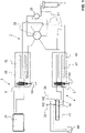
- the figure 1 shows a functional diagram of a nuclide activation system 4 combined with a ball measuring system 3, as is used, for example, in a nuclear power plant with a nuclear reactor 1.
- Two shut-off devices 5 according to the invention are used in an associated line system 2 .
- An example of an embodiment of such a shut-off device according to the invention is Figures 2 to 10 shown closer.
- Figures 11 to 14 a further example of an embodiment of a shut-off device according to the invention is shown.
- the figure 15 shows a opposite of figure 1 expanded functional scheme, which is particularly suitable for the dual use of a shut-off device according to this further example.
- Functionally identical or similar features of different embodiments are each provided with the same reference symbols in the drawings.
- the line system 2 has a large number of lines 21 which, depending on the case, represent part of the ball measuring system 3 or of the nuclide activation system 4 or belong to both systems. It serves to introduce measuring spheres or nuclide activation targets into one or usually several instrumentation fingers of the nuclear reactor 1 and to transport them out again after a sufficient dwell time.
- a propellant fluid preferably a propellant gas, is used to transport the measuring spheres or targets, ie the spheres or targets are transported through the line system 2 by means of positive and negative pressure.
- nitrogen (N 2 ) is preferred as the propellant gas.
- the lines 21 are dimensioned with regard to their inside diameters such that the balls or targets can be easily conveyed by means of the propellant gas without being able to change positions with one another. Accordingly, the lines 21 have an inner line diameter which approximately corresponds to the outer diameter of the spheres or targets. At most, the inner diameter of the lines 21 is slightly larger, ie preferably by a maximum of 10%, more preferably by a maximum of 5%, than the outer diameter of the spheres and the targets. The spheres and the targets preferably have approximately the same outside diameter.
- the ball measuring system 3 has a parking position 32, which is provided for parking the measuring balls when no measurement is being carried out.
- the measuring balls are preferably arranged next to one another in several parallel rows. Each row preferably corresponds to an instrumentation finger in the nuclear reactor 1, i.e. the arrangement of the measuring balls in the parking position 32 corresponds to the arrangement of the measuring balls in the nuclear reactor 1.
- a shut-off device 5 is provided, which can also be referred to as a ball stopper.
- a shield 33 is provided which completely surrounds the parking position 32 and the blocking device 5 in order to protect the surroundings from radioactive radiation.
- the measuring balls are preferably steel balls containing vanadium.
- a measuring table 31 with several radiation detectors is provided for measuring the activity of the balls irradiated in the nuclear reactor 1 .
- the measuring balls are preferably arranged next to one another in several parallel rows, analogously to the parking position 32 , with each row preferably corresponding to exactly one instrumentation finger in the nuclear reactor 1 . This makes it easy to draw from the measured radiation of each measuring sphere to the neutron flux at a corresponding point in the nuclear reactor 1 getting closed.
- Corresponding connecting lines 21 are provided in order to transport the measuring balls from the parking position 32 to the measuring table 31 or in the opposite direction.
- the blocking unit has an actuating element, explained in more detail below, with which the passages from the parking position 32 to the connecting lines 21 and thus to the measuring table 31 for the balls can be released or blocked.
- the nuclide activation system 4 also has a parking position 42, which is provided for parking the nuclide activation target.
- the targets are preferably arranged next to one another in several parallel rows.
- each row preferably corresponds to one instrumentation finger in the nuclear reactor 1, i.e. the arrangement of the targets in the parked position 32 corresponds to the arrangement of the measuring balls in the nuclear reactor 1.
- the parked position is occupied by the targets in particular when the shotgun system 2 is used to carry out a measurement must be carried out.
- dummy targets can be used for these points, which are only used for the correct arrangement of the targets in the nuclear reactor 1, but are not intended for the subsequent e.g. medical use.
- shut-off device 5 In order to stop the targets being returned from the nuclear reactor 1 when they reach the parking position 42, a shut-off device 5 is also provided here.
- a shield 43 is provided which completely surrounds the parking position 42 and the blocking device 5 in order to protect the surroundings from radioactive radiation.
- the parking position 42 can be connected via corresponding connecting lines 21 and a connection box 41 to removal lines which open into a removal container 44 .
- the actuating element of the shut-off device 5 is moved to the open position so that the passage in the shut-off device 5 is released and the targets can be transported to the removal container 44.
- connection box 41 is used to introduce nitrogen, i.e. the propellant gas, into the nuclide activation system 4 via corresponding N 2 lines 24. If the targets should be removed from the nuclide activation system 4, the N 2 lines 24 are uncoupled from the connection box 41, for example by hand, and instead the sampling lines are coupled. Corresponding quick couplings 45 are advantageously provided for this purpose.
- the transport of the targets from the parking position 42 into the removal container 44 can take place, for example, using the force of gravity.
- the measuring balls and the nuclide activation targets are distributed from the parking positions 32 and 42 to the various instrumentation fingers of the nuclear reactor 1 by means of one or more distributor points 22.
- the lines 21 leading to the park positions 32 and 42 are connected to the lines 21 by means of the distributor points 22 , which lead to the respective instrumentation fingers.
- the distributor switch (s) 22 can, for example, according to the information in the DE 10 2017 125 606 A1 be designed.
- An emergency closing device 23 is also provided in the line system 2 in the immediate vicinity of the reactor core 1 .
- the emergency closing device 23 is used, for example, to separate the line system section near the reactor from the line system section remote from the reactor if a leak occurs in one of the instrumentation fingers.
- the emergency closing device can be designed as a rotary valve, in particular as a ball valve. In principle, however, it is also conceivable to use a shut-off device according to the invention as an emergency closing device 23 .
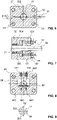
- shut-off device 5 used in the ball measuring system 3 and in the nuclide activation system 4 is described below with reference to FIG Figures 2 to 10 explained in more detail.
- the shut-off device 5 has a plurality of base bodies 52, here exactly six, which are arranged one behind the other.
- the base bodies 52 are all configured identically and are each cuboid as a whole.
- a continuous channel 521 extends through each of the base bodies 52, which is used for the passage of the measuring balls or targets.
- the channels 521 of the various base bodies 52 all extend parallel to one another.
- the inside diameter of the channels 521 preferably corresponds to that of the lines 21, ie it is approximately the same size or at most slightly larger than the outside diameter of the measuring spheres or targets.
- a line connection 51 is provided on both sides of the base body 52 and is used to connect the channel 521 to a line 21 .
- a guide block 55, 56 and then a cover 53, 54 are arranged at the ends of the row of base bodies 52, respectively.
- the front cover 53 and the rear cover 54 are clamped against the guide blocks 55, 56 and thus the base body 52 by means of connecting screws 59.
- the row of base bodies 52 is thus clamped in the manner of a sandwich between the guide blocks 55, 56 on the one hand and the covers 53, 54.
- the connecting screws 59 four of which are provided in the present exemplary embodiment, extend through the front cover 53, the guide blocks 55, 56 and the base bodies 52 and are screwed into the rear cover 54 by means of mutual threaded engagement.
- the screw heads of the connecting screws 59 rest against the front cover 53 .
- a washer 591 is arranged in each case between the screw heads and the cover 53 .
- a through opening 57 extends through the front cover 53, the guide blocks 55, 56 and all the base bodies 52 and intersects the channels 521 of the base bodies 52 perpendicularly in each case.
- a piston rod 58 is pushed into the passage opening 57 and forms an actuating element of the shut-off device 5 and is used to open or shut off the channels 521 of the base body 52 .
- the piston rod 58 is pushed completely into the through opening 57, i.e. up to the stop on a stop surface 541 of the rear cover 54. In this position, the piston rod 58 is in its open position, which is thus defined by the stop on the stop surface 541, and extends through all base bodies 52 as well as the guide blocks 55, 56 and the front cover 53 completely. Inside the base body 52 and the guide blocks 55, 56, the piston rod 58 has an outer diameter which approximately corresponds to the inner diameter of the through-opening 57 or is at most slightly smaller.
- the shut-off device 5 Apart from the outstanding piston rod 58, the shut-off device 5 as The whole thing has a compact cuboid shape. It is thus designed to save space and can be assembled.
- the piston rod 58 has a plurality of channels 581, in this case exactly six, which in each case extend completely through the piston rod 58 perpendicularly to the longitudinal extension thereof.
- the channels 581 are arranged in such a way that they each represent a continuation of the channels 521 of the base body 52 through the piston rod 58 . The passage for the measuring balls or targets through the channels 521 is thus released via the channels 581 .
- the drive 50 can be, for example, an electric rotary or linear drive or a hydraulic drive.
- the drive 50 is connected to the piston rod 58 at the free end which protrudes outwards from the front cover 53 (in the views of FIGS figures 4 and 10 each on the right-hand side).
- the channels 581 of the piston rod 58 are arranged in the closed position in relation to the channels 521 of the base body 52 shifted.
- the passage for the measuring balls and the targets through the channels 521 of the base body 52 is thus blocked by the piston rod 58 .
- a very small displacement is sufficient to bring the piston rod 58 from the open position to the closed position or vice versa.
- the demands on the drive 50 are relatively low, so that its dimensions can also be smaller.
- the piston rod 58 When shifting, the piston rod 58 is guided in guide bushings 551 and 565 of the guide blocks 55 and 56, respectively. Like in the figure 8 As can be seen, the piston rod 58 preferably has a lateral flattened area 583 in the area of the rear guide block 56 and rests with this on a contact plate 561 . The piston rod 58 is secured against rotation as a result.
- the contact plate 561 is fastened to the guide block 56 in a cavity of the guide block 56 by means of screws 562 . Access to the screws 562 is via openings 563 which are provided on the opposite side of the cavity and can be closed by means of plugs 564 .
- the channels 521 of the base body 52 are closed for the measuring balls and the targets in the present embodiment, as mentioned.
- the channels 521 are not closed either in the open position or in the closed position for the propellant gas.
- the base body 52 and/or the piston rod 58 each have an annular groove 522 in the areas of the channels 521 or 581 opening towards the through-opening 57 .
- the annular groove 522 which in particular in the Figures 6 and 9 can be seen, extends starting from the channel openings in each case annularly around the piston rod 58 and thus ensures an unhindered gas exchange between the two channel parts of the channels 521 arranged on both sides of the piston rod 58 even in the closed position.
- sealing rings 582 are attached to the piston rod 58 between the channels 581 in each case.
- the sealing rings 582 seal off the piston rod 58 from the base bodies 52 .
- seals 523 are provided in order to seal the base bodies 52 against one another and against the guide blocks 55 and 56 .
- the seals 523 thus prevent propellant gas from escaping between the base bodies 52 and the guide blocks 55, 56 to the outside.
- Another sealing ring 552 is arranged in the front guide block 55 on the piston rod 58 . It serves to seal the passage between the guide block 55 and the piston rod 58 therethrough.
- the sealing ring 552 can be pressed against the guide block 55 in the longitudinal direction of the piston rod 58 by means of a pressure sleeve 555 (see Fig figure 7 ).
- the pressing force of the pressure sleeve 555 and thus the sealing effect of the sealing ring 552 can be adjusted with the aid of two adjusting screws 531.
- a sliding plate 553 and an end ring 554 are arranged between the sealing ring 552 and the pressure sleeve 555 .
- the piston rod 58 extends through the sealing ring 552, the slide plate 553, the end ring 554 and the pressure sleeve 555 therethrough.
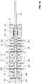
- FIG. 11 to 14 a further exemplary embodiment of a shut-off device 5 according to the invention is shown.
- an integrated pneumatic drive with a drive piston 556 by means of a threaded pin 559 or otherwise on the Piston rod 58 is attached and within a piston chamber 557 is movable.
- the piston chamber 557 is located inside the guide block 55 and is bounded by the guide block 55 and the cover 53 .
- a gas connection 550 opens into the piston chamber 557 on both sides of the drive piston 556 in order to introduce pressurized gas into the piston chamber 557 depending on the desired direction of movement of the piston rod 58 .
- the gas thus serves as a working medium in order to move the piston rod 58 from the open position to the closed position or vice versa, the gas being compressed air, for example, but preferably nitrogen.
- the drive piston 556 is sealed circumferentially relative to the inner wall of the guide block 55 by means of a piston seal 558 .
- two magnetic sensors 532, 543 are also provided in order to measure the position of the piston rod 58, ie the actuating element, in relation to the base bodies 52.
- a first magnetic sensor 532 is, as in FIG figure 13 as can be seen, is positioned in a hole in the cover 53 provided for this purpose, and a second magnetic sensor 543 in a hole in the cover 54 that is also provided for this purpose a permanent magnet attached.
- Figures 11 to 14 also has a threaded hole arranged centrally in the cover 54, which is closed with a locking screw 542 during normal operation.
- the locking screw 542 can be unscrewed and a handle 585 can be screwed into a threaded hole provided at the corresponding end of the piston rod 58.
- the piston rod 58 can then be manually adjusted from the open position to the closed position or vice versa using the handle 585 as a makeshift.
- FIG. 15 A functional diagram, which is particularly for the embodiment of the shut-off device 5 of Figures 2 to 9 suitable is in the figure 15 shown.
- the functional scheme of figure 15 differs from that of figure 1 That the two shut-off devices 5 each correspond on the one hand to those which are in the Figures 11 to 14 is shown, and that, on the other hand, gas switching lines 25 are present in order to control the pneumatic drives integrated in the shut-off devices 5.
- One of the two gas connections 550 of the first shut-off device 5 connected in each case to one of the two gas connections 550 of the second shut-off device 5 by means of a gas switching line 25 in such a way that pressurization of the corresponding gas switching line 25 leads to the first shut-off device 5 being closed and the second shut-off device 5 being opened or vice versa.
- the invention described here is not limited to the embodiments mentioned and a large number of modifications are possible.
- the actuating element which is formed here by the piston rod 58, does not necessarily have to be as in the exemplary embodiment of FIG Figures 2 to 10 have a circular cross-section.
- the actuating element could just as well have a rectangular, in particular square, cross section, for example.
- the channels 521 do not necessarily all have to extend parallel to one another, but could also extend in different directions.
- the channels 581 of the actuating element would then have to be aligned accordingly.
- the blocking device could also have only a single base body, which has one or even several channels for the measuring balls or targets.
Landscapes
- Physics & Mathematics (AREA)
- Engineering & Computer Science (AREA)
- High Energy & Nuclear Physics (AREA)
- Plasma & Fusion (AREA)
- General Engineering & Computer Science (AREA)
- Life Sciences & Earth Sciences (AREA)
- Health & Medical Sciences (AREA)
- General Physics & Mathematics (AREA)
- Molecular Biology (AREA)
- Spectroscopy & Molecular Physics (AREA)
- Chemical Kinetics & Catalysis (AREA)
- General Chemical & Material Sciences (AREA)
- Chemical & Material Sciences (AREA)
- Monitoring And Testing Of Nuclear Reactors (AREA)
- Pipe Accessories (AREA)
Priority Applications (5)
| Application Number | Priority Date | Filing Date | Title |
|---|---|---|---|
| EP20208937.1A EP4002390A1 (fr) | 2020-11-20 | 2020-11-20 | Système de blocage permettant de bloquer les solides irradiés ou à irradier |
| CA3199866A CA3199866A1 (fr) | 2020-11-20 | 2021-11-02 | Dispositif de blocage pour arreter des corps solides irradies ou destines a etre irradies |
| EP21805468.2A EP4248465A1 (fr) | 2020-11-20 | 2021-11-02 | Dispositif de blocage pour arrêter des corps solides irradiés ou destinés à être irradiés |
| US18/037,933 US20240006089A1 (en) | 2020-11-20 | 2021-11-02 | Blocking device for stopping solid bodies that have been irradiated or that are to be irradiated |
| PCT/EP2021/080328 WO2022106187A1 (fr) | 2020-11-20 | 2021-11-02 | Dispositif de blocage pour arrêter des corps solides irradiés ou destinés à être irradiés |
Applications Claiming Priority (1)
| Application Number | Priority Date | Filing Date | Title |
|---|---|---|---|
| EP20208937.1A EP4002390A1 (fr) | 2020-11-20 | 2020-11-20 | Système de blocage permettant de bloquer les solides irradiés ou à irradier |
Publications (1)
| Publication Number | Publication Date |
|---|---|
| EP4002390A1 true EP4002390A1 (fr) | 2022-05-25 |
Family
ID=73543134
Family Applications (2)
| Application Number | Title | Priority Date | Filing Date |
|---|---|---|---|
| EP20208937.1A Withdrawn EP4002390A1 (fr) | 2020-11-20 | 2020-11-20 | Système de blocage permettant de bloquer les solides irradiés ou à irradier |
| EP21805468.2A Pending EP4248465A1 (fr) | 2020-11-20 | 2021-11-02 | Dispositif de blocage pour arrêter des corps solides irradiés ou destinés à être irradiés |
Family Applications After (1)
| Application Number | Title | Priority Date | Filing Date |
|---|---|---|---|
| EP21805468.2A Pending EP4248465A1 (fr) | 2020-11-20 | 2021-11-02 | Dispositif de blocage pour arrêter des corps solides irradiés ou destinés à être irradiés |
Country Status (4)
| Country | Link |
|---|---|
| US (1) | US20240006089A1 (fr) |
| EP (2) | EP4002390A1 (fr) |
| CA (1) | CA3199866A1 (fr) |
| WO (1) | WO2022106187A1 (fr) |
Families Citing this family (1)
| Publication number | Priority date | Publication date | Assignee | Title |
|---|---|---|---|---|
| US20240071642A1 (en) * | 2022-08-31 | 2024-02-29 | Westinghouse Electric Company Llc | Nuclear flux thimble irradiation target insertion and retrieval mechanism |
Citations (5)
| Publication number | Priority date | Publication date | Assignee | Title |
|---|---|---|---|---|
| DE1294575B (de) * | 1962-04-18 | 1969-05-08 | Westinghouse Electric Corp | Vorrichtung zur Messung der oertlichen Neutronendichteverteilung im Inneren eines Kernreaktors |
| DE4119609A1 (de) * | 1990-06-15 | 1991-12-19 | Barmag Barmer Maschf | Vorrichtung zur intermittierenden schmieroelversorgung |
| ES2273527A1 (es) * | 2003-06-30 | 2007-05-01 | Hynergreen Technologies, S.A. | Sistema de evacuacion de anhidrido carbonico en camaras isobaricas, submarinos, batiscafos y otros vehiculos sumergibles, con propulsion anaerobia. |
| US20130170927A1 (en) * | 2011-12-28 | 2013-07-04 | Yogeshwar Dayal | Systems and methods for processing irradiation targets through a nuclear reactor |
| DE102017125606A1 (de) | 2017-11-02 | 2019-05-02 | Kernkraftwerk Gösgen-Däniken Ag | Ventilblock für ein molchbares und/oder festkörperführendes Leitungssystem und Verteilerleitungssystem |
-
2020
- 2020-11-20 EP EP20208937.1A patent/EP4002390A1/fr not_active Withdrawn
-
2021
- 2021-11-02 US US18/037,933 patent/US20240006089A1/en active Pending
- 2021-11-02 WO PCT/EP2021/080328 patent/WO2022106187A1/fr not_active Ceased
- 2021-11-02 CA CA3199866A patent/CA3199866A1/fr active Pending
- 2021-11-02 EP EP21805468.2A patent/EP4248465A1/fr active Pending
Patent Citations (5)
| Publication number | Priority date | Publication date | Assignee | Title |
|---|---|---|---|---|
| DE1294575B (de) * | 1962-04-18 | 1969-05-08 | Westinghouse Electric Corp | Vorrichtung zur Messung der oertlichen Neutronendichteverteilung im Inneren eines Kernreaktors |
| DE4119609A1 (de) * | 1990-06-15 | 1991-12-19 | Barmag Barmer Maschf | Vorrichtung zur intermittierenden schmieroelversorgung |
| ES2273527A1 (es) * | 2003-06-30 | 2007-05-01 | Hynergreen Technologies, S.A. | Sistema de evacuacion de anhidrido carbonico en camaras isobaricas, submarinos, batiscafos y otros vehiculos sumergibles, con propulsion anaerobia. |
| US20130170927A1 (en) * | 2011-12-28 | 2013-07-04 | Yogeshwar Dayal | Systems and methods for processing irradiation targets through a nuclear reactor |
| DE102017125606A1 (de) | 2017-11-02 | 2019-05-02 | Kernkraftwerk Gösgen-Däniken Ag | Ventilblock für ein molchbares und/oder festkörperführendes Leitungssystem und Verteilerleitungssystem |
Also Published As
| Publication number | Publication date |
|---|---|
| WO2022106187A1 (fr) | 2022-05-27 |
| CA3199866A1 (fr) | 2022-05-27 |
| US20240006089A1 (en) | 2024-01-04 |
| EP4248465A1 (fr) | 2023-09-27 |
Similar Documents
| Publication | Publication Date | Title |
|---|---|---|
| DE3801998C1 (fr) | ||
| DE3525597A1 (de) | Hilfsgeraet fuer ein sicherheitsventil | |
| EP0452702A2 (fr) | Dispositif de fixation pour une unité de mouvement linéaire | |
| EP4002390A1 (fr) | Système de blocage permettant de bloquer les solides irradiés ou à irradier | |
| DE19539262C2 (de) | Kolbenstangenloser Zylinder | |
| EP3480826A1 (fr) | Bloc de soupape pour un système de conduites raclable et / ou conduisant un corps solide et système de distribution | |
| DE102019216083B4 (de) | Fahrgast-Rückhaltevorrichtung und Fahrgeschäft-Fahrgasteinheit | |
| DE3239930A1 (de) | Hydraulisch steuerbares sperrventil, insbesondere fuer die rohrbruchsicherung | |
| DE2534279C2 (de) | Ventil | |
| EP2898514B1 (fr) | Dispositif pour introduire un lubrifiant dans une tuyauterie | |
| DE2249601C3 (de) | Parallel-Platten-Absperrschieber | |
| DE2260598A1 (de) | Hydraulische steuervorrichtung, insbesondere fuer das ein- und ausfahren der steuerstaebe eines kernreaktors | |
| DE20005776U1 (de) | Linearwegschieber | |
| DE1589532B2 (de) | Beschickungsanlage fuer kernreaktoren mit kugelfoermigen brennstoffelementen | |
| CH657790A5 (de) | Vorrichtung zum verdichten von koernigen formstoffen. | |
| DE2909504A1 (de) | Magnetventil | |
| DE102014207393B4 (de) | Ventil | |
| DE2259868A1 (de) | Schieberventil | |
| DE1550511A1 (de) | Absperrschieber | |
| EP0224825B1 (fr) | Ressort hydraulique pouvant être bloqué | |
| DE3818859A1 (de) | Sicherheitsabsperreinrichtung | |
| DE1589532C3 (de) | Beschickungsaniage für Kernreaktoren mit kugelförmigen Brennstoffelementen | |
| DE1775464B1 (de) | Ringfoermige Anordnung druckmittelbetaetigter Klappen zur Querschnittsveraenderung von Stroemungskanaelen,insbesondere fuer Triebwerksschubduesen | |
| DE3445955C2 (fr) | ||
| EP0870141B1 (fr) | Soupape d'arret |
Legal Events
| Date | Code | Title | Description |
|---|---|---|---|
| PUAI | Public reference made under article 153(3) epc to a published international application that has entered the european phase |
Free format text: ORIGINAL CODE: 0009012 |
|
| STAA | Information on the status of an ep patent application or granted ep patent |
Free format text: STATUS: THE APPLICATION HAS BEEN PUBLISHED |
|
| AK | Designated contracting states |
Kind code of ref document: A1 Designated state(s): AL AT BE BG CH CY CZ DE DK EE ES FI FR GB GR HR HU IE IS IT LI LT LU LV MC MK MT NL NO PL PT RO RS SE SI SK SM TR |
|
| STAA | Information on the status of an ep patent application or granted ep patent |
Free format text: STATUS: THE APPLICATION IS DEEMED TO BE WITHDRAWN |
|
| 18D | Application deemed to be withdrawn |
Effective date: 20221126 |