EP4002401A1 - Selbstvorbiegende transformatorklemmen - Google Patents
Selbstvorbiegende transformatorklemmen Download PDFInfo
- Publication number
- EP4002401A1 EP4002401A1 EP20212886.4A EP20212886A EP4002401A1 EP 4002401 A1 EP4002401 A1 EP 4002401A1 EP 20212886 A EP20212886 A EP 20212886A EP 4002401 A1 EP4002401 A1 EP 4002401A1
- Authority
- EP
- European Patent Office
- Prior art keywords
- transformer
- plate
- clamp
- curvature
- transformer clamp
- Prior art date
- Legal status (The legal status is an assumption and is not a legal conclusion. Google has not performed a legal analysis and makes no representation as to the accuracy of the status listed.)
- Granted
Links
Images




Classifications
-
- H—ELECTRICITY
- H01—ELECTRIC ELEMENTS
- H01F—MAGNETS; INDUCTANCES; TRANSFORMERS; SELECTION OF MATERIALS FOR THEIR MAGNETIC PROPERTIES
- H01F27/00—Details of transformers or inductances, in general
- H01F27/24—Magnetic cores
- H01F27/26—Fastening parts of the core together; Fastening or mounting the core on casing or support
- H01F27/263—Fastening parts of the core together
-
- H—ELECTRICITY
- H01—ELECTRIC ELEMENTS
- H01F—MAGNETS; INDUCTANCES; TRANSFORMERS; SELECTION OF MATERIALS FOR THEIR MAGNETIC PROPERTIES
- H01F41/00—Apparatus or processes specially adapted for manufacturing or assembling magnets, inductances or transformers; Apparatus or processes specially adapted for manufacturing materials characterised by their magnetic properties
- H01F41/02—Apparatus or processes specially adapted for manufacturing or assembling magnets, inductances or transformers; Apparatus or processes specially adapted for manufacturing materials characterised by their magnetic properties for manufacturing cores, coils, or magnets
Definitions
- the present disclosure relates generally to transformer clamps, and more particularly to transformer clamps and related methods.
- a transformer typically includes a core, coils, and a transformer clamp structure.
- the transformer clamp structure provides the stiffness required to withstand the loads in the transformer under different work conditions like lifting the transformer, short circuit operation, and transport of the transformer.
- the clamps must provide enough pressure to the core sheets to reduce or prevent the occurrence of vibration of the transformer core sheets when the transformer is in operation.
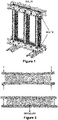
- the transformer clamps are made with a pre-bending process.
- the transformer clamps are designed to be bent after assembly to have a small curved shape along their geometry (pre-bending). This small curved shape enables giving pressure on core sheets when the clamp is assembled on the core.
- force is applied to the ends causing the clamp to take on a flattened shape, once the clamp is unbended it provides the pressure required by the core lamination.
- the pre-bending is illustrated in Figure 2 .
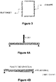
- the rectangular section of the transformer clamps is made by welding two pieces, a C Shape piece and a flat sheet as illustrated in Figure 3 . Once these two pieces are welded, a plastic deformation is required to create the pre-bending. One way this is done is by applying a load in the middle of the clamps as shown in Figures 4A and 4B .
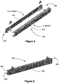
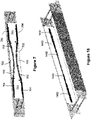
- Figures 5 and 6 illustrate an example of a two piece C Shape 502 and flat sheet 504 of transformer clamp 500 that is assembled but not yet bent after assembly using the process illustrated in Figures 4A and 4B . Simulations have been carried out to validate the pressure exerted on the transformer core finding that the transformer clamp of Figures 5 and 6 bent after assembly do not provide a constant pressure along the transformer core as shown in Figure 7 .
- the white color 700 indicates a minimum pressure
- the lighter color 702 indicates a pressure nearly half as much as the desired pressure
- the darker color 704 indicates pressure equal to or higher than the desired pressure.
- the lighter color 702 may be even lighter, indicating an even lower pressure when the transformer clamp of Figure 5 and 6 is overtightened as illustrated in Figure 8 .
- a transformer clamp includes a first plate having a curved portion of a predetermined curvature between a first end portion and a second end portion of the transformer clamp.
- the transformer clamp includes a second plate attached to the first plate and curved based on the curvature of the curved portion, wherein the curvature enables the transformer clamp to distribute a substantially uniform pressure across a first surface of a transformer coupled to the transformer clamp.
- the pre-bending can be achieved without requiring loads to bend.
- the resulting geometry of the transformer clamp reduces manufacturing time, and increases the accuracy of the transformer clamp providing the desired dimensions.
- the transformer clamp supports loads in different work conditions and provides a substantially uniform pressure over the transformer part coupled to the transformer clamp.
- a method for creating a transformer clamp.
- the method includes determining, based on a first surface of a transformer, a curvature for a first plate of the transformer clamp.
- the method includes forming a curved portion in the first plate between a first end portion and a second end portion of the transformer clamp based on the curvature determined.
- the method includes curving a second plate along the curved portion to form a curved contact surface having a curvature based on the curvature of the curved portion, the curved contact surface reshaping to apply a substantially uniform pressure across the first surface of the transformer coupled to the curved contact surface in response to a clamping force applied to the first end portion and the second end portion of the transformer clamp.
- a transformer clamp for a transformer includes a plate connected to at least one tab portion proximate an end portion of the plate.
- the transformer clamp includes a mounting mechanism connected to the plate, the mounting mechanism having a back wall adjacent a surface of a transformer core of the transformer and having sidewalls, each sidewall adjacent to one of the at least one tab portion and enabled to engage the one of the at least one tab portion responsive to the transformer core applying a force to the mounting mechanism in response to another force applied to the transformer core.
- Figure 9 is an illustration of plates 902, 906 of a transformer clamp 900 according to some embodiments of inventive concepts.
- Figure 10 illustrates the plates 902, 906 of the transformer clamp 900 when the transformer clamp has been assembled.
- Figures 9 - 11 according to various embodiments of these inventive concepts, a T-section geometry is used that allows optimizing of the cross-section material in relation to the greater stresses required.
- the first plate 902 of transformer clamp 900 has variable lengths from a first length L1 to a second length L2 where the second length is greater than the first length.
- the pre-bending is achieved by joining two sheets together perpendicularly to form the transformer clamp 900.
- first plate 902 (e.g., a flat sheet) has a curved portion 904 and is joined to the plate 906.
- the first plates 902, and the second plate 906 may be joined by welding the first plate 902 and the second plate 906 together.
- the second plate 906 is attached perpendicular to first plate 902 so that the first plate 902 is joined along the center axis of second plate 906.
- the second plate 906 follows the curvature 910 illustrated in Figure 11 , achieving an assembly with an arched geometry that imparts a bending of the second plate 906.
- the bending forms a curved contact surface 908 of the second plate 906.
- the curvature 910 typically ranges from 3 mm to 8 mm and depends on the desired pressure to be applied to the transformer and the dimensions of the transformer.
- the desired pressure in various embodiments of inventive concepts is on the order of 0.15 MPa.
- the second plate 906 may be attached perpendicular to the first plate 902 anywhere along the first plate 906 provided that the second plate 906 follows the curvature 910.
- the curvature is determined based on a desired pressure to be applied to the transformer core of the transformer and a dimension of the transformer core.
- the desired pressure may be around 0.15 MPa.
- the curvature 910 may be determined by determining a maximum deformation of transformer clamp based on a distributed load and length of the transformer clamp, which in turn is based on the transformer core length.
- the cross section of the transformer clamp plate 902 needs to be increased in accordance with the deformation of the transformer clamp plate, which requires a variable cross section.
- the maximum deformation ⁇ is determined for the transformer clamp using a distributed load Q* where Q* is calculated based on the contact surface area of the transformer clamp surface area and the pressure on the transformer core to be reached (e.g., 0.15 MPa).
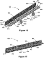
- the first plate 902 may include a plurality of mounting holes 912 formed approximately midway between an end portion 914, 916 of the first plate 902 and a middle portion 918 of the first plate 902 to enable a tie rod 1802 (see Figures 16 - 17 ) to be connected to the first plate 902 at each of the plurality of mounting holes 912.
- Support tabs 920 can be attached proximate each mounting hole 912 of the first plate 902. Each support tab 920 can have a mounting hole 922 to enable lifting of the transformer 1800 as illustrated in Figures 16-17 . In some embodiments of inventive concepts, not all support tabs 920 have the mounting hole 922. Instead, only the transformer clamps 900 that are used to lift the transformer have mounting holes 922.
- the support tab 920 may have a slot 924 that fits into a slot 926 of first plate 902 as illustrated in Figure 16 . This enables the support tabs 920 to be mounted at fixed locations on the first plate 902.
- the second plate 906 may have mounting holes 928 proximate each end portion 930, 932 of the second plate 906.
- the mounting holes 928 are used to connect the transformer clamp 900 to another transformer clamp operatively coupled to an opposite surface of a transformer being clamped. Note that the clamping force is applied to the end portions 930, 932 of the transformer clamp 900 responsive to the transformer clamp being connected to the second transformer clamp.
- the second transformer clamp may be any transformer clamp including the transformer clamp 900.
- the second plate 906 may, in some embodiments of the transformer clamp 900, have proximate the center of each end portion of the second plate 906 a slot 934 which receives a tab portion 936 of the first plate 902. This aligns the second plate 906 to the first plate 902 along the center axis of the second plate 906.
- Figure 18 illustrates simulations that were performed to validate the pressure exerted on the transformer clamp of Figures 9-11 , and 16-17 .
- the white color 1400 indicate a minimum pressure and the dark color 1402 indicates pressure equal to or higher than the desired pressure.
- the simulations that were performed show that the T-section beam shape of the transformer clamp 900 enables a pressure of 0.15 MPa to be reached along the core as shown.
- the transformer clamp 900 provides a substantially uniform pressure across the surface of the transformer core.
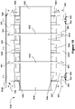
- FIG 19 is a front view of a transformer assembly clamped by the transformer clamp illustrated in Figure 16 and Figure 20 is an isometric view of the transformer clamp.
- the transformer clamps 900A-900D are shown clamping a transformer 1800.
- the transformer clamp 900A and transformer clamp 900B are connected to each other by the tie rods 1902 via mounting holes 912. Other types of connectors may be used to connect the transformer clamp 900A to the transformer clamp 900B via the mounting holes 912.
- the transformer clamp 900A using the mounting holes 928 proximate each end portion 914, 916 of second plate 906, is also connected to transformer clamp 900C that is coupled to an opposite surface of the transformer 1900 of the surface where the transformer clamp 900A is coupled to the transformer 1900.
- the clamping force is applied to the end portions 914, 916 of the transformer clamp via the transformer clamp 900A being connected to the transformer clamp 900C via mounting mechanism 1904.
- Transformer clamp 900B is similarly connected to transformer clamp 900D.
- the transformer clamp 900 is typically connected to a transformer core surface of a transformer core 1906 above or below the winding area of the transformer windings 1908.
- the transformer clamps 900 are above the top of winding area of the transformer windings 1908 and below the bottom of the winding area of the transformer windings 1908.
- the transformer clamps 900A to 900D hold the transformer cores in place with a substantially uniform pressure across the transformer core at the top and bottom of the transformer cores.
- supports 1910 may be used to reduce or prevent the occurrence of transformer windings 1908 moving towards the transformer clamps 900A to 900D during transport of the transformer 1900.
- the transformer clamps 900 hold the supports 1910 in place when the tie rods 1902 are tightened to hold the transformer clamps together.
- the tightening of the tie rods 1902 pushes the plate 902 against the supports 1910.
- the supports may be wood supports, plastic supports, or any other type of material that is of sufficient stiffness to withstand the force applied by the transformer clamp when the tie rods 1902 are tightened to hold transformer clamps 900 together (e.g., transformer clamp 900A to transformer clamp 900B and transformer clamp 900C to transformer clamp 900D).
- the second plate 906 may have additional mounting holes and support tabs to aid in positioning the transformer clamps to the correct position on the transformer such as mounting holes 938, 940 and support tabs 942 as illustrated in Figures 19 and 20 .
- mounting holes 938, 940 and support tabs 942 as illustrated in Figures 19 and 20 .
- mounting hole 938 may be used as an alternative place to lift the transformer.
- FIGS 21 and 22 illustrate a C-shape and plate transformer clamp 2100 according to various embodiments of inventive concepts.
- the C-shape 2102 has a top plate 2104, a side plate 2106 and a bottom plate 2108.
- the top plate 2104 and bottom plate 2108 have variable lengths from a first length L1 to a second length L2 where the second length is greater than the first length.
- the top plate 2104 and bottom plate 2108 have a curved portion 2110 and are joined to the plate 2112 where the curvature of the curved portion 2110 is determined as described above.
- the C-shape 2102 and the plate 2112 may be joined by welding the top plate 2104 and bottom plate 2108 to the plate 2112.
- the plate 2112 is attached perpendicular to the top plate 2104 and the bottom plate 2108 of the C-shape 2102 along the top and the bottom of plate 2112.
- the plate 2112 follows the curvature 2114 illustrated in Figure 21 , achieving an assembly with an arched geometry that imparts a bending of the plate 2112.
- the bending forms a curved contact surface 2116 of the plate 2112.
- the curvature 2114 typically ranges from 3 mm to 8 mm and depends on the desired pressure to be applied to the transformer and the dimensions of the transformer.
- the desired pressure in various embodiments of inventive concepts is on the order of 0.15 MPa.
- the transformer clamp 2100 may include a plurality of mounting holes 2118 formed proximate the end portion 2120, 2122 of the C-shape 2102 to enable a tie rod to be connected to the top plate 2104 and bottom plate 2108 at each of the plurality of mounting holes 2118.
- Support tabs 2124 can be attached proximate each mounting hole 2118. Each support tab 2124 can have a mounting hole 2126 to enable lifting of the transformer. In some embodiments of inventive concepts, not all support tabs 2126 have the mounting hole 2128. Instead, only the transformer clamps 2100 that are used to lift the transformer have mounting holes 2126.
- the side plate 2106 of C-shape 2102 and plate 2112 may have mounting holes 2128 proximate each end portion 2120, 2122 of the C-shape 2102.
- the mounting holes 2128 are used to connect the transformer clamp 2100 to another transformer clamp operatively coupled to an opposite surface of a transformer being clamped. Note that the clamping force is applied to the end portions 2120, 2122 of the transformer clamp 2100 responsive to the transformer clamp being connected to the second transformer clamp.
- the second transformer clamp may be any transformer clamp including the transformer clamp 2100.
- Figure 23 illustrates the mounting mechanism 1904 and the tab portion 936.
- the tab portion 936 aligns the second plate 906 to the first plate 902 during assembly of the transformer clamp 900.
- the tab portion 936 in some embodiments of inventive concepts may also be used to reduce and, in some scenarios, prevent the occurrence of damage to the bolts 2300 used to attach the mounting mechanism 1904 to the transformer clamps 900.
- the transformer 1900 may be subject to force 2400, as illustrated in Figure 24 , that are sufficiently high enough to cause the transformer cores 1906 to move in the direction of the force 2400.
- the force 2400 may be the result of a vehicle transporting the transformer 1900 braking hard to avoid an accident, a chain breaking when the transformer 1900 is being lifted, etc.
- the transformer cores 1906 move in the direction of the force 2400 and push on the back wall 2302 of mounting mechanism 1904.
- the force 2400 may be in the direction shown in Figure 24 or in the opposite direction of the direction shown.
- the plate 2304 reduces or prevents the occurrence of transformer cores 1906 bending the back wall 2302 when the transformer cores 1906 push against the back wall 2302.
- the pushing on the back wall 2302 can result in the mounting mechanism 1904 pushing against the bolts 2300 located in slots 2306 of sides wall 2308.
- the bolts 2300 may shear off.
- the clamping force applied to the transformer clamp 900 is significantly reduced and the transformer clamp 900 would no longer provide the substantially uniform pressure across the transformer core 1906 and can damage the transformer 1900.
- the occurrence of the mounting mechanism 1904 from moving far enough to shear off the bolts 2300 is reduced or prevented.
- the reduction or prevention of the occurrence of movement is due to the tab portion 936 being proximate the edge 2310 of side wall 2308.
- the edge 2310 pushes against tab portion 936 and the tab portion 936 reduces or prevents the occurrence of movement of the side wall 2308 from moving any further, which prevents or reduces the occurrence of the bolts 2300 from being exposed to forces from the transformer core movement that could shear the bolts 2300.
- the edge 2310 of side wall 2308 may be moved to engage (i.e., contact) the tab portion 936 during installation of the mounting mechanism 1904.
- the occurrence of the edge 2310 of side wall 2308 from moving is reduced or prevented, which in turn prevents or reduces the occurrence of the back wall 2302 of mounting mechanism 1904 from moving when the force 2400 is applied to the transformer cores 1906.
- Figure 25 illustrates how a tab can be added to the C-shape and flat plate transformer clamp 500 and C-shape and flat plate transformer clamp 2100 to operate like the tab portion 936 of transformer clamp 900.
- a tab 2500 can be mounted proximate the end portions of the flat plate 504, 2112 of the C-shape and flat plate transformers 500, 2100. The tab 2500 can then be used to reduce or prevent the occurrence of the mounting mechanism 1904 from moving as described above.
- Figure 26 illustrates another embodiment of the mounting mechanism according to various embodiments of inventive concepts.
- the mounting mechanism 2600 does not have plate 2304.
- the thickness 2602 of the back wall 2302 is increased to better withstand the force applied by the transformer core moving to reduce, and in some cases prevent, the occurrence of movement of the sidewalls 2308 towards the tab portion 936, 2500.
- Figure 27 illustrates the mounting mechanism 2600 connecting transformer clamps to each other.
- Figure 28 illustrates a further embodiment of the mounting mechanism according to various embodiments of inventive concepts.
- the back wall 2302 of mounting mechanism 2800 has an increased dimension and plates 2802 and 2804 are formed by bending the back wall 2304.
- the two plates 2802 and 2804 of the back wall 2302 act to stiffen the back wall 2302 to better withstand the force applied by the transformer core moving to reduce and in some cases, prevent, the occurrence of movement of the sidewalls 2308 towards the tab portion 936, 2500.
- Figure 29 illustrates the mounting mechanism 2800 connecting transformer clamps to each other.
- Figure 30 illustrates a process of creating the transformer clamp 900, 2100 in an embodiment of inventive concepts.
- a curvature to be applied to a first plate of the transformer clamp is determined based on a first surface of a transformer.
- the curvature 910 of the curved portion 904 to be applied to the first plate 902 is determined based on at least one of the length of the transformer clamp 900 (which in turn is based on transformer core parameters such as a dimension of the transformer core), and the pressure to be applied to the transformer clamp (e.g., 0.15 MPa).
- the length or the pressure or both the length and the pressure is used.
- the curvature 2114 to be applied to the top plate 2104 and the bottom plate 2108 of C-shape 2102 is determined based on at least one of the length of the transformer clamp 2100 (which in turn is based on transformer core parameters), and the pressure to be applied to the transformer clamp (e.g., 0.15 MPa). Thus, at least one of the length or the pressure or both the length and the pressure is used.
- a curvature portion 2110 in the first plate is formed between a first end portion 2120 and a second end portion 2122 of the transformer clamp based on the curvature determined to be applied.
- the curved portion 904 is formed between end portions 914, 916 of the transformer clamp 900.
- the curved portion may be formed by laser cutting, water cutting, etc.
- the curved portion 2110 is formed between end portions 2120, 2122.
- a second plate is attached to the first plate by curving the second plate along the curved portion to provide a curved contact surface having a curvature based on the curvature of the curved portion, the curved contact surface reshaping to apply a substantially uniform pressure across the first surface of the transformer coupled to the curved contact surface in response to a clamping force applied to the first end portion and the second end portion of the transformer clamp.
- the plate 906 of transformer clamp 900 may be curved along the curved portion 904 of plate 902 to form the curved contact surface 908.
- the force applied to the transformer clamp 900 by tightening of the transformer clamp 900 to the mounting mechanism 1904 provides the force sufficient to reshape the curved contact surface 908 to apply the substantially uniform pressure across the first surface (e.g., transformer core) of a transformer coupled to the curved contact surface 908.
- the plate 2112 of transformer clamp 2100 may be curved along the curved portion 2110 of plates 2104, 2108 to form the curved contact surface 2116.
- the force applied to the transformer clamp 2100 by tightening of the transformer clamp 2100 to the mounting mechanism 1904 provides the force sufficient to reshape the curved contact surface 2116 to apply the substantially uniform pressure across the first surface (e.g., transformer core) of a transformer coupled to the curved contact surface 2116.
- a plurality of mounting holes is formed in the first plate, each of the plurality of mounting holes formed approximately midway between an end of the first plate and a middle of the first plate to enable a tie rod to be connected to the first plate at each of the plurality of mounting holes.
- mounting holes 912 may be formed in first plate 902 either before or after the second plate 906 is connected to first plate 902.
- a plurality of mounting holes 2118 is formed in plates 2104, 2108 proximate the end portions 2120, 2122.
- mounting holes are formed proximate each end of the second plate for connecting the second plate to a second transformer clamp operatively coupled to an opposite surface of the first surface wherein the clamping force is applied to the first end and the second end of the transformer clamp responsive to the transformer clamp being connected to the second transformer clamp.
- mounting holes 928 may be formed in second plate 906 either before or after the second plate 906 is connected to first plate 902.
- mounting holes 2128 may be formed in the plate 2106 and flat plate 2112.
- a support tab is attached proximate each mounting hole of the first plate.
- each support tab has a mounting hole to enable lifting of the transformer.
- only support tabs that are part of transformer clamps that are at the top of a transformer have mounting holes.
- An example of a support tab having holes is support tab 920 having mounting hole 922.
- another example of a support tab having holes is support tabs 2124.
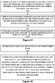
- FIG 32 illustrates a process of connecting transformer clamps with a mounting mechanism that reduces and, in some scenarios, prevents the occurrences of damage to the bolts used to attach the mounting mechanism to the transformer clamps.
- the tab portion is part of a plate of the transformer clamp.
- tab portion 936 is part of plate 902 of transformer clamp 900 and engages plate 906 during assembly of transformer clamp 900.
- the tab portion is connected by welding the tab.
- tab portion 2500 may be welded on plate 504, 2112.
- the tab portion is connected adjacent to an end portion of a plate of the transformer clamp that is contacting the transformer core.
- plate 906 of transformer clamp 900, plate 2112 of transformer clamp 2100, and the flat plate 504 of transformer clamp 500 touch the transformer core.
- the tab portion 936, 2500 is provided adjacent to an end portion 506, 508, 930, 932, 2120, 2122 of a plate 504, 906, 2112 of the transformer clamp.
- a mounting mechanism having a back wall and sidewalls is connected to transformer clamps by placing the back wall adjacent a surface of the transformer core of the transformer and connecting each sidewall to one of the transformer clamps adjacent to one of the at least one tab portion, wherein each sidewall is enabled to engage the one of the at least one tab portion responsive to the transformer core applying a force to the mounting mechanism in response to another force applied to the transformer core.
- mounting mechanism 1904, 2600, 2800 having a back wall 2302 and sidewalls 2308 is connected to the transformer clamps 500, 900, 2100 by placing back wall 2302 adjacent a side surface of the transformer core 1906 and connecting each sidewall 2308 to one of the transformer clamps 500, 900, 2100 adjacent to one of the tab portions (936, 2500).
- the mounting mechanism 1904, 2600, 2800 is attached to the transformer clamps such that one of the sidewalls 2308 engages the at least one tab portion 936, 2500 of one of the transformer clamps.
- the force applied by the transformer does not move the sidewalls 2308 to engage the at least one tab portion 936, 2500 since the sidewalls 2038 are already contacting the at least one tab portion 936, 2500.
- a transformer clamp has been described that provides substantially uniform pressure to the surface of a transformer during operation, increases the accuracy of the manufactured parts to the desired dimensions, provides a reduction in part count which results in lower weight and a simple manufacturing process which leads to a significant reduction in manufacturing costs, and provides a precise curvature to enable the substantial uniform pressure to be achieved.
- the transformer clamp provides a tab portion that enables a mounting mechanism to reduce and/or prevent the occurrence of shear forces from shearing off bolts used to connect the mounting mechanism to the transformer clamp.
- the terms “comprise”, “comprising”, “comprises”, “include”, “including”, “includes”, “have”, “has”, “having”, or variants thereof are open-ended, and include one or more stated features, integers, elements, steps, components or functions but does not preclude the presence or addition of one or more other features, integers, elements, steps, components, functions or groups thereof.
- the common abbreviation “e.g.”, which derives from the Latin phrase “exempli gratia” may be used to introduce or specify a general example or examples of a previously mentioned item, and is not intended to be limiting of such item.
- the common abbreviation “i.e.”, which derives from the Latin phrase “id est,” may be used to specify a particular item from a more general recitation.
Landscapes
- Engineering & Computer Science (AREA)
- Power Engineering (AREA)
- Manufacturing & Machinery (AREA)
- Housings And Mounting Of Transformers (AREA)
- Coils Of Transformers For General Uses (AREA)
Applications Claiming Priority (1)
| Application Number | Priority Date | Filing Date | Title |
|---|---|---|---|
| US202063117036P | 2020-11-23 | 2020-11-23 |
Publications (2)
| Publication Number | Publication Date |
|---|---|
| EP4002401A1 true EP4002401A1 (de) | 2022-05-25 |
| EP4002401B1 EP4002401B1 (de) | 2024-08-14 |
Family
ID=73790011
Family Applications (1)
| Application Number | Title | Priority Date | Filing Date |
|---|---|---|---|
| EP20212886.4A Active EP4002401B1 (de) | 2020-11-23 | 2020-12-09 | Selbstvorbiegende transformatorklemmen |
Country Status (3)
| Country | Link |
|---|---|
| EP (1) | EP4002401B1 (de) |
| CN (1) | CN114530312A (de) |
| PL (1) | PL4002401T3 (de) |
Citations (3)
| Publication number | Priority date | Publication date | Assignee | Title |
|---|---|---|---|---|
| CH387782A (de) * | 1961-05-25 | 1965-02-15 | Oerlikon Maschf | Vorrichtung zum Verspannen von Transformatoreisenkörpern |
| JPS5398916U (de) * | 1977-01-14 | 1978-08-10 | ||
| US20170018354A1 (en) * | 2015-07-16 | 2017-01-19 | Virginia Transformer Corporation | Tension bar |
Family Cites Families (3)
| Publication number | Priority date | Publication date | Assignee | Title |
|---|---|---|---|---|
| CH397854A (de) * | 1961-05-25 | 1965-08-31 | Oerlikon Maschf | Vorrichtung zum Verspannen von Transformatoreisenkörpern |
| CN202049844U (zh) * | 2011-05-05 | 2011-11-23 | 保定天威集团有限公司 | 一种干式变压器用可调方向式钢拉带结构 |
| JP5720471B2 (ja) * | 2011-07-28 | 2015-05-20 | 株式会社デンソー | 磁気部品ユニット |
-
2020
- 2020-12-09 PL PL20212886.4T patent/PL4002401T3/pl unknown
- 2020-12-09 EP EP20212886.4A patent/EP4002401B1/de active Active
-
2021
- 2021-08-06 CN CN202110902649.2A patent/CN114530312A/zh active Pending
Patent Citations (3)
| Publication number | Priority date | Publication date | Assignee | Title |
|---|---|---|---|---|
| CH387782A (de) * | 1961-05-25 | 1965-02-15 | Oerlikon Maschf | Vorrichtung zum Verspannen von Transformatoreisenkörpern |
| JPS5398916U (de) * | 1977-01-14 | 1978-08-10 | ||
| US20170018354A1 (en) * | 2015-07-16 | 2017-01-19 | Virginia Transformer Corporation | Tension bar |
Also Published As
| Publication number | Publication date |
|---|---|
| EP4002401B1 (de) | 2024-08-14 |
| PL4002401T3 (pl) | 2025-01-07 |
| CN114530312A (zh) | 2022-05-24 |
Similar Documents
| Publication | Publication Date | Title |
|---|---|---|
| US4074947A (en) | Fittings for connecting columns and beams | |
| JP6316416B2 (ja) | エレベータのガイドレール位置調整システム | |
| EP4002401B1 (de) | Selbstvorbiegende transformatorklemmen | |
| CN217508367U (zh) | 定子铁芯的定位装置 | |
| RU2554362C2 (ru) | Хомут анкера для подъема бетонных элементов | |
| KR100343498B1 (ko) | 기둥보강장치 및 이를 이용한 기둥보강방법 | |
| US3108200A (en) | Dynamo stator assemblies having resiliently mounted field coils | |
| KR20150074101A (ko) | 인터로킹 코어 프레임을 갖는 변압기 | |
| US11745238B2 (en) | Clamping strap | |
| CN112599326A (zh) | 铁芯叠片夹紧结构及夹紧方法 | |
| US5430425A (en) | Integrated frame system | |
| US20220170495A1 (en) | Support Sleeve And Arrangement Of Support Sleeve | |
| CN212285395U (zh) | 小型型钢矫正胎具 | |
| JPH0684659A (ja) | 変圧器鉄心 | |
| JPH07187545A (ja) | エレベータ駆動用リニア誘導モータの2次導体 | |
| JPH08189189A (ja) | 型枠上部矯正治具 | |
| US20200246853A1 (en) | Method of manufacturing pipe | |
| JP3470461B2 (ja) | 変圧器 | |
| CN214601612U (zh) | 一种钢筋弯折工具 | |
| KR102757505B1 (ko) | H빔에 예압을 주는 방법 | |
| CN115461963A (zh) | 电动机的定子以及电动机的定子制造方法 | |
| CN1833078A (zh) | 带拉紧装置 | |
| JP4265185B2 (ja) | 配管固定具 | |
| KR102867274B1 (ko) | 변압기 및 변압기 제조방법 | |
| CN220955642U (zh) | 一种止水带固定装置 |
Legal Events
| Date | Code | Title | Description |
|---|---|---|---|
| PUAI | Public reference made under article 153(3) epc to a published international application that has entered the european phase |
Free format text: ORIGINAL CODE: 0009012 |
|
| STAA | Information on the status of an ep patent application or granted ep patent |
Free format text: STATUS: REQUEST FOR EXAMINATION WAS MADE |
|
| 17P | Request for examination filed |
Effective date: 20220209 |
|
| AK | Designated contracting states |
Kind code of ref document: A1 Designated state(s): AL AT BE BG CH CY CZ DE DK EE ES FI FR GB GR HR HU IE IS IT LI LT LU LV MC MK MT NL NO PL PT RO RS SE SI SK SM TR |
|
| P01 | Opt-out of the competence of the unified patent court (upc) registered |
Effective date: 20230527 |
|
| RAP1 | Party data changed (applicant data changed or rights of an application transferred) |
Owner name: HITACHI ENERGY LTD |
|
| GRAP | Despatch of communication of intention to grant a patent |
Free format text: ORIGINAL CODE: EPIDOSNIGR1 |
|
| STAA | Information on the status of an ep patent application or granted ep patent |
Free format text: STATUS: GRANT OF PATENT IS INTENDED |
|
| INTG | Intention to grant announced |
Effective date: 20240311 |
|
| GRAS | Grant fee paid |
Free format text: ORIGINAL CODE: EPIDOSNIGR3 |
|
| GRAA | (expected) grant |
Free format text: ORIGINAL CODE: 0009210 |
|
| STAA | Information on the status of an ep patent application or granted ep patent |
Free format text: STATUS: THE PATENT HAS BEEN GRANTED |
|
| AK | Designated contracting states |
Kind code of ref document: B1 Designated state(s): AL AT BE BG CH CY CZ DE DK EE ES FI FR GB GR HR HU IE IS IT LI LT LU LV MC MK MT NL NO PL PT RO RS SE SI SK SM TR |
|
| REG | Reference to a national code |
Ref country code: GB Ref legal event code: FG4D |
|
| REG | Reference to a national code |
Ref country code: CH Ref legal event code: EP |
|
| REG | Reference to a national code |
Ref country code: DE Ref legal event code: R096 Ref document number: 602020035679 Country of ref document: DE |
|
| REG | Reference to a national code |
Ref country code: IE Ref legal event code: FG4D |
|
| REG | Reference to a national code |
Ref country code: LT Ref legal event code: MG9D |
|
| REG | Reference to a national code |
Ref country code: NL Ref legal event code: MP Effective date: 20240814 |
|
| PG25 | Lapsed in a contracting state [announced via postgrant information from national office to epo] |
Ref country code: NO Free format text: LAPSE BECAUSE OF FAILURE TO SUBMIT A TRANSLATION OF THE DESCRIPTION OR TO PAY THE FEE WITHIN THE PRESCRIBED TIME-LIMIT Effective date: 20241114 |
|
| REG | Reference to a national code |
Ref country code: AT Ref legal event code: MK05 Ref document number: 1714089 Country of ref document: AT Kind code of ref document: T Effective date: 20240814 |
|
| PG25 | Lapsed in a contracting state [announced via postgrant information from national office to epo] |
Ref country code: GR Free format text: LAPSE BECAUSE OF FAILURE TO SUBMIT A TRANSLATION OF THE DESCRIPTION OR TO PAY THE FEE WITHIN THE PRESCRIBED TIME-LIMIT Effective date: 20241115 Ref country code: NL Free format text: LAPSE BECAUSE OF FAILURE TO SUBMIT A TRANSLATION OF THE DESCRIPTION OR TO PAY THE FEE WITHIN THE PRESCRIBED TIME-LIMIT Effective date: 20240814 Ref country code: PT Free format text: LAPSE BECAUSE OF FAILURE TO SUBMIT A TRANSLATION OF THE DESCRIPTION OR TO PAY THE FEE WITHIN THE PRESCRIBED TIME-LIMIT Effective date: 20241216 Ref country code: FI Free format text: LAPSE BECAUSE OF FAILURE TO SUBMIT A TRANSLATION OF THE DESCRIPTION OR TO PAY THE FEE WITHIN THE PRESCRIBED TIME-LIMIT Effective date: 20240814 |
|
| PG25 | Lapsed in a contracting state [announced via postgrant information from national office to epo] |
Ref country code: BG Free format text: LAPSE BECAUSE OF FAILURE TO SUBMIT A TRANSLATION OF THE DESCRIPTION OR TO PAY THE FEE WITHIN THE PRESCRIBED TIME-LIMIT Effective date: 20240814 |
|
| PG25 | Lapsed in a contracting state [announced via postgrant information from national office to epo] |
Ref country code: LV Free format text: LAPSE BECAUSE OF FAILURE TO SUBMIT A TRANSLATION OF THE DESCRIPTION OR TO PAY THE FEE WITHIN THE PRESCRIBED TIME-LIMIT Effective date: 20240814 |
|
| PG25 | Lapsed in a contracting state [announced via postgrant information from national office to epo] |
Ref country code: AT Free format text: LAPSE BECAUSE OF FAILURE TO SUBMIT A TRANSLATION OF THE DESCRIPTION OR TO PAY THE FEE WITHIN THE PRESCRIBED TIME-LIMIT Effective date: 20240814 Ref country code: IS Free format text: LAPSE BECAUSE OF FAILURE TO SUBMIT A TRANSLATION OF THE DESCRIPTION OR TO PAY THE FEE WITHIN THE PRESCRIBED TIME-LIMIT Effective date: 20241214 |
|
| PG25 | Lapsed in a contracting state [announced via postgrant information from national office to epo] |
Ref country code: HR Free format text: LAPSE BECAUSE OF FAILURE TO SUBMIT A TRANSLATION OF THE DESCRIPTION OR TO PAY THE FEE WITHIN THE PRESCRIBED TIME-LIMIT Effective date: 20240814 |
|
| PG25 | Lapsed in a contracting state [announced via postgrant information from national office to epo] |
Ref country code: ES Free format text: LAPSE BECAUSE OF FAILURE TO SUBMIT A TRANSLATION OF THE DESCRIPTION OR TO PAY THE FEE WITHIN THE PRESCRIBED TIME-LIMIT Effective date: 20240814 Ref country code: RS Free format text: LAPSE BECAUSE OF FAILURE TO SUBMIT A TRANSLATION OF THE DESCRIPTION OR TO PAY THE FEE WITHIN THE PRESCRIBED TIME-LIMIT Effective date: 20241114 |
|
| PG25 | Lapsed in a contracting state [announced via postgrant information from national office to epo] |
Ref country code: RS Free format text: LAPSE BECAUSE OF FAILURE TO SUBMIT A TRANSLATION OF THE DESCRIPTION OR TO PAY THE FEE WITHIN THE PRESCRIBED TIME-LIMIT Effective date: 20241114 Ref country code: PT Free format text: LAPSE BECAUSE OF FAILURE TO SUBMIT A TRANSLATION OF THE DESCRIPTION OR TO PAY THE FEE WITHIN THE PRESCRIBED TIME-LIMIT Effective date: 20241216 Ref country code: NO Free format text: LAPSE BECAUSE OF FAILURE TO SUBMIT A TRANSLATION OF THE DESCRIPTION OR TO PAY THE FEE WITHIN THE PRESCRIBED TIME-LIMIT Effective date: 20241114 Ref country code: NL Free format text: LAPSE BECAUSE OF FAILURE TO SUBMIT A TRANSLATION OF THE DESCRIPTION OR TO PAY THE FEE WITHIN THE PRESCRIBED TIME-LIMIT Effective date: 20240814 Ref country code: LV Free format text: LAPSE BECAUSE OF FAILURE TO SUBMIT A TRANSLATION OF THE DESCRIPTION OR TO PAY THE FEE WITHIN THE PRESCRIBED TIME-LIMIT Effective date: 20240814 Ref country code: IS Free format text: LAPSE BECAUSE OF FAILURE TO SUBMIT A TRANSLATION OF THE DESCRIPTION OR TO PAY THE FEE WITHIN THE PRESCRIBED TIME-LIMIT Effective date: 20241214 Ref country code: HR Free format text: LAPSE BECAUSE OF FAILURE TO SUBMIT A TRANSLATION OF THE DESCRIPTION OR TO PAY THE FEE WITHIN THE PRESCRIBED TIME-LIMIT Effective date: 20240814 Ref country code: GR Free format text: LAPSE BECAUSE OF FAILURE TO SUBMIT A TRANSLATION OF THE DESCRIPTION OR TO PAY THE FEE WITHIN THE PRESCRIBED TIME-LIMIT Effective date: 20241115 Ref country code: FI Free format text: LAPSE BECAUSE OF FAILURE TO SUBMIT A TRANSLATION OF THE DESCRIPTION OR TO PAY THE FEE WITHIN THE PRESCRIBED TIME-LIMIT Effective date: 20240814 Ref country code: ES Free format text: LAPSE BECAUSE OF FAILURE TO SUBMIT A TRANSLATION OF THE DESCRIPTION OR TO PAY THE FEE WITHIN THE PRESCRIBED TIME-LIMIT Effective date: 20240814 Ref country code: BG Free format text: LAPSE BECAUSE OF FAILURE TO SUBMIT A TRANSLATION OF THE DESCRIPTION OR TO PAY THE FEE WITHIN THE PRESCRIBED TIME-LIMIT Effective date: 20240814 Ref country code: AT Free format text: LAPSE BECAUSE OF FAILURE TO SUBMIT A TRANSLATION OF THE DESCRIPTION OR TO PAY THE FEE WITHIN THE PRESCRIBED TIME-LIMIT Effective date: 20240814 |
|
| PG25 | Lapsed in a contracting state [announced via postgrant information from national office to epo] |
Ref country code: SM Free format text: LAPSE BECAUSE OF FAILURE TO SUBMIT A TRANSLATION OF THE DESCRIPTION OR TO PAY THE FEE WITHIN THE PRESCRIBED TIME-LIMIT Effective date: 20240814 Ref country code: DK Free format text: LAPSE BECAUSE OF FAILURE TO SUBMIT A TRANSLATION OF THE DESCRIPTION OR TO PAY THE FEE WITHIN THE PRESCRIBED TIME-LIMIT Effective date: 20240814 Ref country code: RO Free format text: LAPSE BECAUSE OF FAILURE TO SUBMIT A TRANSLATION OF THE DESCRIPTION OR TO PAY THE FEE WITHIN THE PRESCRIBED TIME-LIMIT Effective date: 20240814 |
|
| PG25 | Lapsed in a contracting state [announced via postgrant information from national office to epo] |
Ref country code: EE Free format text: LAPSE BECAUSE OF FAILURE TO SUBMIT A TRANSLATION OF THE DESCRIPTION OR TO PAY THE FEE WITHIN THE PRESCRIBED TIME-LIMIT Effective date: 20240814 |
|
| PG25 | Lapsed in a contracting state [announced via postgrant information from national office to epo] |
Ref country code: CZ Free format text: LAPSE BECAUSE OF FAILURE TO SUBMIT A TRANSLATION OF THE DESCRIPTION OR TO PAY THE FEE WITHIN THE PRESCRIBED TIME-LIMIT Effective date: 20240814 |
|
| PG25 | Lapsed in a contracting state [announced via postgrant information from national office to epo] |
Ref country code: SK Free format text: LAPSE BECAUSE OF FAILURE TO SUBMIT A TRANSLATION OF THE DESCRIPTION OR TO PAY THE FEE WITHIN THE PRESCRIBED TIME-LIMIT Effective date: 20240814 Ref country code: IT Free format text: LAPSE BECAUSE OF FAILURE TO SUBMIT A TRANSLATION OF THE DESCRIPTION OR TO PAY THE FEE WITHIN THE PRESCRIBED TIME-LIMIT Effective date: 20240814 |
|
| REG | Reference to a national code |
Ref country code: DE Ref legal event code: R097 Ref document number: 602020035679 Country of ref document: DE |
|
| PLBE | No opposition filed within time limit |
Free format text: ORIGINAL CODE: 0009261 |
|
| STAA | Information on the status of an ep patent application or granted ep patent |
Free format text: STATUS: NO OPPOSITION FILED WITHIN TIME LIMIT |
|
| PG25 | Lapsed in a contracting state [announced via postgrant information from national office to epo] |
Ref country code: MC Free format text: LAPSE BECAUSE OF FAILURE TO SUBMIT A TRANSLATION OF THE DESCRIPTION OR TO PAY THE FEE WITHIN THE PRESCRIBED TIME-LIMIT Effective date: 20240814 |
|
| 26N | No opposition filed |
Effective date: 20250515 |
|
| REG | Reference to a national code |
Ref country code: CH Ref legal event code: PL |
|
| PG25 | Lapsed in a contracting state [announced via postgrant information from national office to epo] |
Ref country code: LU Free format text: LAPSE BECAUSE OF NON-PAYMENT OF DUE FEES Effective date: 20241209 |
|
| PG25 | Lapsed in a contracting state [announced via postgrant information from national office to epo] |
Ref country code: SE Free format text: LAPSE BECAUSE OF FAILURE TO SUBMIT A TRANSLATION OF THE DESCRIPTION OR TO PAY THE FEE WITHIN THE PRESCRIBED TIME-LIMIT Effective date: 20240814 |
|
| REG | Reference to a national code |
Ref country code: BE Ref legal event code: MM Effective date: 20241231 |
|
| PG25 | Lapsed in a contracting state [announced via postgrant information from national office to epo] |
Ref country code: BE Free format text: LAPSE BECAUSE OF NON-PAYMENT OF DUE FEES Effective date: 20241231 |
|
| PG25 | Lapsed in a contracting state [announced via postgrant information from national office to epo] |
Ref country code: CH Free format text: LAPSE BECAUSE OF NON-PAYMENT OF DUE FEES Effective date: 20241231 |
|
| PG25 | Lapsed in a contracting state [announced via postgrant information from national office to epo] |
Ref country code: IE Free format text: LAPSE BECAUSE OF NON-PAYMENT OF DUE FEES Effective date: 20241209 |
|
| PGFP | Annual fee paid to national office [announced via postgrant information from national office to epo] |
Ref country code: DE Payment date: 20251211 Year of fee payment: 6 |
|
| PGFP | Annual fee paid to national office [announced via postgrant information from national office to epo] |
Ref country code: GB Payment date: 20251219 Year of fee payment: 6 |
|
| PGFP | Annual fee paid to national office [announced via postgrant information from national office to epo] |
Ref country code: FR Payment date: 20251229 Year of fee payment: 6 |
|
| PGFP | Annual fee paid to national office [announced via postgrant information from national office to epo] |
Ref country code: TR Payment date: 20251203 Year of fee payment: 6 |
|
| PGFP | Annual fee paid to national office [announced via postgrant information from national office to epo] |
Ref country code: PL Payment date: 20251128 Year of fee payment: 6 |