EP4002416A1 - Elektromagnetisches relais mit einem elastisch deformierbaren beweglichen teil - Google Patents
Elektromagnetisches relais mit einem elastisch deformierbaren beweglichen teil Download PDFInfo
- Publication number
- EP4002416A1 EP4002416A1 EP21208635.9A EP21208635A EP4002416A1 EP 4002416 A1 EP4002416 A1 EP 4002416A1 EP 21208635 A EP21208635 A EP 21208635A EP 4002416 A1 EP4002416 A1 EP 4002416A1
- Authority
- EP
- European Patent Office
- Prior art keywords
- spring part
- armature
- actuator
- movable spring
- electromagnetic relay
- Prior art date
- Legal status (The legal status is an assumption and is not a legal conclusion. Google has not performed a legal analysis and makes no representation as to the accuracy of the status listed.)
- Granted
Links
Images


Classifications
-
- H—ELECTRICITY
- H01—ELECTRIC ELEMENTS
- H01H—ELECTRIC SWITCHES; RELAYS; SELECTORS; EMERGENCY PROTECTIVE DEVICES
- H01H50/00—Details of electromagnetic relays
- H01H50/16—Magnetic circuit arrangements
- H01H50/18—Movable parts of magnetic circuits, e.g. armature
- H01H50/24—Parts rotatable or rockable outside coil
- H01H50/26—Parts movable about a knife edge
-
- H—ELECTRICITY
- H01—ELECTRIC ELEMENTS
- H01H—ELECTRIC SWITCHES; RELAYS; SELECTORS; EMERGENCY PROTECTIVE DEVICES
- H01H50/00—Details of electromagnetic relays
- H01H50/64—Driving arrangements between movable part of magnetic circuit and contact
- H01H50/643—Driving arrangements between movable part of magnetic circuit and contact intermediate part performing a rotating or pivoting movement
-
- H—ELECTRICITY
- H01—ELECTRIC ELEMENTS
- H01H—ELECTRIC SWITCHES; RELAYS; SELECTORS; EMERGENCY PROTECTIVE DEVICES
- H01H50/00—Details of electromagnetic relays
- H01H50/64—Driving arrangements between movable part of magnetic circuit and contact
- H01H50/645—Driving arrangements between movable part of magnetic circuit and contact intermediate part making a resilient or flexible connection
- H01H50/646—Driving arrangements between movable part of magnetic circuit and contact intermediate part making a resilient or flexible connection intermediate part being a blade spring
-
- H—ELECTRICITY
- H01—ELECTRIC ELEMENTS
- H01H—ELECTRIC SWITCHES; RELAYS; SELECTORS; EMERGENCY PROTECTIVE DEVICES
- H01H50/00—Details of electromagnetic relays
- H01H50/64—Driving arrangements between movable part of magnetic circuit and contact
- H01H50/648—Driving arrangements between movable part of magnetic circuit and contact intermediate part being rigidly combined with armature
-
- H—ELECTRICITY
- H01—ELECTRIC ELEMENTS
- H01H—ELECTRIC SWITCHES; RELAYS; SELECTORS; EMERGENCY PROTECTIVE DEVICES
- H01H50/00—Details of electromagnetic relays
- H01H50/54—Contact arrangements
- H01H50/56—Contact spring sets
Definitions
- the present disclosure relates to the technical field of relays, and in particular, to an electromagnetic relay.
- the electromagnetic relay generally includes a base, a magnetic circuit system, and a contact system.
- the magnetic circuit system includes a coil assembly, an iron core, a yoke and an armature
- the contact system includes a stationary spring part and a movable spring part.
- it is generally necessary to increase the thickness of the movable spring part to improve the current-carrying capacity of the movable spring part.
- making the movable spring part thicker will cause a series of problems such as difficult deformation, high stress, and easy breakage, which will affect the over-travel of contacts and contact pressure of the movable spring part.
- the stress is reduced by optimizing the structure of the movable spring (such as digging grooves, etc.), but this approach is not only unsatisfactory, but also difficult (need to constantly adjust the angle, size, etc. for exploration and simulation), which affects the speed of product development.
- an elastic piece is added to the movable spring part, such as riveting an elastic piece at the tail of the contact, to increase the deformation of the entire movable spring part to achieve over-travel of contacts and contact pressure.
- the contacts need to be riveted with multiple movable springs, the riveting becomes more difficult, the riveting quality is easily affected, and the current-carrying effect may also be affected to a certain extent.
- the present disclosure provides an electromagnetic relay suitable for heavy loads, which solves the problem that it is difficult to achieve over-travel of contacts and contact pressure after the movable spring is partially thickened under heavy loads, and also avoids the problems caused by optimizing the structure or riveting elastic piece to improve the deformability of the movable spring part.
- an electromagnetic relay includes a base, a magnetic circuit system, a contact system, an actuator and an elastic member.
- the magnetic circuit system includes a coil assembly, an iron core, a yoke and an armature, the coil assembly is mounted on the base, the iron core, the yoke and the armature are respectively arranged at the coil assembly and cooperated with the coil assembly.
- the contact system includes a stationary spring part provided with a stationary contact and a movable spring part provided with a movable contact, the stationary spring part and the movable spring part are respectively arranged on the base.
- the armature is cooperated with the movable spring part to drive the movable spring part to move through the elastic member and the actuator, and when the movable contact and the stationary contact are in a closed state, the elastic member is in a deformed state.
- the elastic member is disposed on the armature, and is connected with the actuator, or in contacted with the actuator to cooperate therewith, or clearance fit with the actuator.
- the elastic member is an elastic plate.
- the elastic plate is Y-shaped, and two ends of the elastic plate at a same side face downwards and are connected to the armature respectively, a remained end opposite to the two ends faces upwards and is connected with the actuator, or in contacted with the actuator to cooperate therewith, or clearance fit with the actuator.
- the armature is L-shaped, and comprises a first armature portion and a second armature portion, wherein the first armature portion is arranged at an outside of the yoke and cooperated with the yoke, and is connected with the elastic member, the second armature portion is cooperated with a pole surface of the iron core.
- the actuator is rotatably connected to the base to make the actuator drive the movable spring part to move through swinging.
- the actuator is provided with two legs, the two legs are respectively connected to the base through rotating shafts and shaft holes that cooperate with each other.
- the movable spring part comprises a plurality of movable springs which are stacked together, and one of the movable springs is provided with an arc-shaped arch; a structure formed by stacking the plurality of movable springs is provided with the movable contact at the top and a lead-out portion at the bottom.
- the magnetic circuit system is in a vertical type and is installed on the base inversely, the armature is restricted and reset by a hinge spring connected to the yoke;
- the base is provided with a retaining wall between the magnetic circuit system and the contact system, and a top of the retaining wall is higher than a top of the armature, or, a top end of the retaining wall is flush with a top end of the armature;
- the top of the retaining wall is provided with a notch, and the actuator is cooperated with the elastic member through the notch.
- the actuator is provided with a first baffle, the first baffle is blocked between a position where the elastic member and the actuator cooperate and the movable spring part;
- the base is connected with a case, and the magnetic circuit system, the contact system, the actuator and the elastic member are accommodated in a case cavity of the case;
- the case is provided with a second baffle, and a bottom end of the second baffle is in contact with or clearance fit with the top end of the retaining wall.
- the actuator is provided with at least two first protrusions facing the magnetic circuit system and at least two second protrusions facing the contact system, each of the first protrusions is respectively connected to the elastic member, and each of the second protrusions is respectively connected to the movable spring part of the contact system.
- the armature is L-shaped, and comprises a first armature portion and a second armature portion, the armature is arranged at a knife edge of the yoke of the magnetic circuit system and is able to swing, and the first armature portion of the armature corresponding to the movable spring part is connected to the elastic member.
- the elastic member is an elastic plate; the elastic plate is provided with at least two first slots or at least two first sockets, which are inserted and fitted one by one with the at least two first protrusions.
- first slots which are respectively located on opposite sides of the elastic plate in the width direction thereof, and two ends of each first slot in a thickness direction of the elastic plate are respectively open; an end of each first slot away from the movable spring part are respectively provided with a first outer flange.
- the movable spring part is provided with at least two second slots or at least two second sockets, which are inserted and fitted one by one with the at least two second protrusions.
- each second slot there are two second slots which are respectively located on opposite sides of the movable spring part in a width direction thereof, and two ends of each second slot in a thickness direction of the movable spring part are respectively open, a side of each second slot away from the armature are respectively provided with a second outer flange.
- the actuator is provided with a first baffle which is blocked between the movable spring part and the elastic member; the first protrusions are located on a side of the first baffle facing the armature, and the second protrusions are located on a side of the first baffle facing the movable spring part.
- the present disclosure has the following beneficial effects:
- the electromagnetic relay of the present disclosure also includes an elastic member
- the armature cooperates with the movable spring part and drives the movable spring part to move through the elastic member and the actuator, and when the movable contact and the stationary contact are in a closed state, the elastic member is in a deformed state, so that the present disclosure can use the deformation of the elastic member to assist or facilitate the movable spring part to achieve over-travel of the contacts and contact pressure.
- the elastic member is disposed on the armature, and is connected with the actuator, or in contacted with the actuator to cooperate therewith, or clearance fit with the actuator, so that the cooperation of the armature, the elastic member and the actuator is more reliable.
- the elastic member is preferably an elastic plate to make it easier to assemble.
- the elastic plate is Y-shaped, which helps to improve the flexibility of the elastic plate, thereby further improving the elastic deformability of the elastic plate.
- the actuator is rotatably connected to the base to make the actuator drive the movable spring part to move through swinging, which realizes the simple assembly of the actuator, and avoid the problems of shavings that are easily generated by the traditional clamping method.
- the movable spring part adopts a design of stacking movable springs, which can increase the current-carrying capacity and save space; one of the movable springs is provided with an arc-shaped arch, which can increase the flexibility of the movable spring part and obtain a better coordination between the magnetic fore of the magnetic circuit system and the rection force of the movable spring part.
- the magnetic circuit system is in a vertical type and is installed on the base inversely, the base is provided with a retaining wall between the magnetic circuit system and the contact system, and a top of the retaining wall is higher than a top of the armature, or, a top end of the retaining wall is flush with a top end of the armature, so that the electromagnetic relay of the present disclosure can use the retaining wall to increase the creepage distance and the clearance between the magnetic circuit system and the contact system, and achieve high insulation performance.
- the electromagnetic relay of the present disclosure is further provided with the first baffle and the second baffle, which can further improve the insulation performance of the present disclosure.
- the electromagnetic relay of the present disclosure has a compact overall structure and a small volume, and solves the problem that the traditional relay is difficult to achieve heavy load and a small volume.
- the actuator is provided with at least two first protrusions facing the magnetic circuit system and at least two second protrusions facing the contact system, each of the first protrusions is respectively connected to a part of the armature of the magnetic circuit system, and each of the second protrusions is respectively connected to the movable spring part of the contact system, so that the two ends of the actuator can form at least two point limits respectively, thereby the actuator is not easy to shake, and the stability of the electrical parameters of the relay is improved.
- the elastic member is an elastic plate, which makes the structure of the elastic member simpler and makes the connection with the armature and the actuator more convenient.
- the arrangement of the first outer flange/the second outer flange can prevent the actuator from rubbing out plastic shavings during assembly.
- an electromagnetic relay includes a base 1, a magnetic circuit system, a contact system, and an actuator 8.
- the magnetic circuit system includes a coil assembly 2, an iron core 5, a yoke 3 and an armature 4.
- the coil assembly 2 is mounted on the base 1, and the iron core 5, the yoke 3 and the armature 4 are respectively arranged at the correspondingly adapted positions of the coil assembly 2.
- the coil assembly 2 includes a bobbin 21 and an enameled wire 22 wound around the bobbin 21, the iron core 5 is inserted into the bobbin 21.
- the yoke 3 includes a first yoke portion 31 and a second yoke portion 32, the first yoke portion 31 and the second yoke portion 32 are connected so that the yoke 3 has an L-shape, the first yoke portion 31 is riveted to one end of the iron core 5, and the second yoke portion 32 is fitted on the side of the coil assembly 2, as shown in FIG. 2 .
- the armature 4 includes a first armature portion 41 and a second armature portion 42. The first armature portion 41 and the second armature portion 42 are connected so that the armature 4 has an L-shaped.
- the first armature portion 41 is arranged at the outside of the second yoke portion 32 of the yoke 3 and cooperated with the yoke 3, and the second armature portion 42 is arranged under and cooperated with the pole surface of the other end of the iron core 5. That is, when the first armature portion 41 moves in a direction away from the second yoke portion 32, the second armature portion 42 moves toward the pole surface of the other end of the iron core 5.
- the contact system includes a stationary spring part 7 provided with a stationary contact 71 and a movable spring part 6 provided with a movable contact 61, the stationary spring part 7 and the movable spring part 6 are respectively arranged on the base 1.
- the electromagnetic relay of the present disclosure also includes an elastic member 90, the armature 4 cooperates with the movable spring part 6 and drives the movable spring part 6 to move through the elastic member 90 and the actuator 8, and when the movable contact 61 and the stationary contact 71 are in a closed state, the elastic member 90 is in a deformed state to assist or facilitate the movable spring part to achieve over-travel of the contacts and contact pressure.
- the elastic member 90 is disposed on the armature 4 and is in contacted with the actuator 8 to cooperate with the actuator 8, but it is not limited to this.
- the elastic member 90 is connected to the actuator 8 or has a clearance fit with the actuator 8 (that is, before the elastic member 90 promotes the actuator to move, there is a gap between the elastic member 90 and the actuator 8).
- the elastic member 90 is disposed on the actuator 8 and located between the actuator 8 and the movable spring part 6.
- the elastic member 90 is disposed on the actuator 8 and located between the actuator 8 and the armature 4.
- the elastic member 90 may be an elastic plate 9, as shown in FIG.
- the elastic plate 9 has a Y-shape, and the two ends of the elastic plate 9 at the same side face downwards, that is, the opening of the bifurcated part of the elastic plate 9 faces the second armature portion 42, and the two ends are respectively connected to the first armature portion 41, the remaining end of the elastic plate 9 opposite to the two ends described above faces upwards.
- the end opposite to the above-mentioned bifurcated part faces away from the second armature portion 42 and is in contact with and cooperated with the actuator 8.
- the elastic plate 9 and the first armature portion 41 are riveted and fixed to each other, but the connection between the two is not limited to this.
- the elastic plate 9 and the armature 4 are welded and fixed to each other.
- the Y-shape of the elastic plate 9 not only helps to improve the flexibility of the elastic plate 9, but also provides a space for the hinge spring 10 described below to prevent interference between the two.
- the actuator 8 is rotatably connected to the base 1, so that the actuator 8 drives the movable spring part 6 to move through swinging.
- the actuator 8 has two legs 81 and two rotating shafts 82, and the rotating shafts 82 are specifically arranged at the bottom of the legs 81 of the actuator 8.
- the base 1 is provided with shaft holes 11, and the rotating shafts 82 can be inserted into the shaft holes and can rotate.
- the two legs 81 are respectively connected to the base 1 through each of the rotating shafts 82 and each of the shaft holes 11 that cooperate with each other, but it is not limited to this.
- the rotating shafts are arranged on the base, and the shaft holes are arranged on the legs of the actuator.
- the actuator 8 is connected to the base 1 through the rotating shaft 82 and the shaft hole 11 that cooperate with each other to realize the simple assembly of the actuator 8 and avoid the problems of plastic shavings that are likely to be generated when the actuator 8 is installed on the base 1 by the traditional clamping method.
- the movable spring part 6 includes a plurality of movable springs, the plurality of movable springs are stacked together, and one of the movable springs 63 is provided with an arc-shaped arch 631.
- the number of the movable springs is specifically two, the movable spring 62 close to the stationary spring part 7 is a flat sheet, and the movable spring 63 facing away from the stationary spring part 7 is in a shape of long strip and provided with the arc-shaped arch 631.
- the structure formed by stacking the two movable springs 62, 63 is provided with the movable contact 61 at the top and a lead-out portion at the bottom, the lead-out portion is specifically a lead-out piece 64 with a lead-out pin 641.
- the magnetic circuit system is in a vertical type and is installed on the base 1 inversely, that is, the pole surface of the iron core 5 is located below, and the second armature portion 42 of the armature 4 is located below the pole surface of the iron core 5, as shown in FIG. 8 .
- a hinge spring 10 is connected to the yoke 3, and the hinge spring 10 partially penetrates the through slot 43 provided in the first armature portion 41 (As shown in FIG. 3 , the through slot 43 is located between the two ends at the same side of the elastic plate 9, that is, the through slot 43 is located in the opening of the bifurcated part) and snap to the bottom of the armature 4, as shown in FIG. 8 .
- the armature 4 can be restricted and reset by the hinge spring 10.
- the base 1 is provided with a retaining wall 12 between the magnetic circuit system and the contact system, and the top of the retaining wall 12 is higher than the top of the armature 4.
- the top end of the retaining wall 12 is flush with the top end of the armature 4.
- the top of the retaining wall 12 is provided with a notch 121, and the actuator 8 is cooperated with the elastic plate 9 through the notch 121.
- the actuator 8 has a first baffle 83, the first baffle 83 is blocked between the position (that is, the end of the elastic plate 9 facing upward) where the elastic member 90 and the actuator 8 cooperate and the movable spring part 6.
- the two legs 81 of the actuator 8 are disposed on the bottom of the first baffle 83, and the first baffle 83 is provided with an extension 84 on the side facing the elastic plate 9, the extension 84 passes through the notch 121 and contacts and cooperates with the upward end of the elastic plate 9.
- the actuator 8 is connected to the movable spring part 6 or contact fit or clearance fit with the movable spring part 6.
- the first baffle 83 of the actuator 8 is provided with a plurality of protrusions 85 on one side facing the movable spring part 6, and each protrusion 85 contacts and cooperates with the top of the movable spring part 6 respectively.
- the number of the protrusions 85 is specifically two, but it is not limited to this, the two protrusions 85 are arranged side by side on the left and right, and the two protrusions 85 respectively contact and cooperate with one side of the top of the movable spring 62 of the movable spring part 6 close to the stationary spring part 7 one by one.
- the base 1 is connected with a case 20, and the magnetic circuit system, the contact system, the actuator 8 and the elastic plate 9 are accommodated in the case cavity of the case 20.
- the case 20 is provided with a second baffle 201, and the bottom end of the second baffle 201 is in contact or clearance fit with the top end of the retaining wall 12.
- the electromagnetic relay of the embodiment of the present disclosure is a normally open type, but is not limited to this. In other embodiments, the electromagnetic relay of the present disclosure may also be a normally closed type.
- the electromagnetic relay of the present disclosure may also be a normally closed type.
- the elastic plate 9 is elastically deformed (before the movable contact 61 and the stationary contact 71 are in contact with each other, the elastic plate 9 may not be deformed or may deform a little while the first armature portion 41 swings away from the yoke 3), thereby assisting or promoting the movable spring part 6 to achieve over-travel of contacts and ensure the contact pressure.
- the elastic deformation capacity of the elastic plate 9 determines its contribution to the over-travel of contacts and contact pressure of the movable spring part 6.
- the elastic deformation required by the movable spring part 6 to achieve over-travel of contacts and contact pressure can be completely provided by the elastic plate 9, and when the elastic deformation capacity of the elastic plate 9 is general, part of the elastic deformation required by the movable spring part 6 to achieve over-travel of contacts and contact pressure can be provided by the elastic plate 9.
- the present disclosure has lower requirements on the deformability of the movable spring part 6, and solves the problem of difficulty in achieving over-travel of contacts and contact pressure due to the reduced deformation capacity of the movable spring part 6 under heavy load after being thickened, and also avoids the problems caused by optimizing the structure of the movable spring part 6 or riveting an elastic piece in order to improve the deformability.
- the retaining wall 12 is used to wrap the magnetic circuit part, and at the same time, the actuator 8 is provided with the first baffle 83, the case 20 is provided with the second baffle 201, therefore, the magnetic circuit system and the contact system are effectively isolated to achieve high insulation performance, that is to increase the creepage distance and clearance, so that the safety distance can reach 5.5mm or more, which can meet the requirements of reinforced insulation.
- the electromagnetic relay according to embodiments of the present disclosure has a compact overall structure and small volume, the volume is only 30% to 40% of the volume of mainstream products with the same load level of related art, and the load capacity is above 30A, which solves the problem of traditional relays that are difficult to achieve heavy load and a small volume.
- each of both sides of the baffle of the actuator is provided with a pushing rod, one pushing rod on one side is installed in the hole of the movable spring part, and one pushing rod on the other side is installed in the hole of the armature part, alternatively, one side of the baffle of the actuator is provided with a pushing rod which is configured to be installed in the hole of the armature part, the other side of the baffle of the actuator is provided with two pushing rods which are configured to be installed in the holes of the movable spring part.
- the above structure is prone to shaking of the actuator, which in turn affects the stability of the electrical parameters of the electromagnetic relay.
- an electromagnetic relay of the present disclosure includes a base 1, a case 20, a magnetic circuit system, a contact system, an actuator 8' and an elastic member 90.
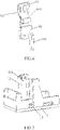
- the actuator 8' is provided with at least two first protrusions 81' facing the magnetic circuit system and at least two second protrusions 82' facing the contact system, each first protrusion 81' is respectively connected to the elastic member 90, and each second protrusion 82' is respectively connected to the movable spring part 6' of the contact system.
- the at least two first protrusions 81' are specifically distributed along the width direction of the armature 4, and the at least two second protrusions 82' are specifically distributed along the width direction of the movable spring part 6', but it is not limited thereto.
- the armature 4 is connected to the elastic member 90, as shown in FIGS. 13-15 , each of the first protrusions 81' is respectively connected to the elastic member 90, and the elastic member 90 is in a deformed state when the contacts of the contact system are closed.
- the armature 4 is specifically L-shaped, and the armature 4 includes a first armature portion 41 and a second armature portion 42.
- the armature 4 is arranged at the knife edge of the yoke 3 of the magnetic circuit system and can be able to swing, the knife edge is a notch at the end of the second yoke portion 32 far away from the first yoke portion 31 (not shown in the figure), the knife edge of the yoke is a well-known technical term in the art, and will not be repeated here.
- the armature 4 is restricted and reset by a hinge spring 10 arranged on the yoke 3.
- the first armature portion 41 of the armature 4 corresponding to the movable spring part 6' is connected to the elastic member 90.
- the elastic member 90 is specifically an elastic plate 9', which is fixedly connected to one side of the armature 4 by means of riveting or welding.
- the elastic plate 9' is provided with at least two first slots 91', which are inserted and fitted one by one with the at least two first protrusions 81'.
- the number of the first slots 91' is two (because the first slots 91' have a one-to-one correspondence with the first protrusions 81', the number of the first protrusions 81' is also two), the two first slots 91' are respectively located on opposite sides of the elastic plate 9' in the width direction thereof, and the two ends of each first slot 91' in the thickness direction of the elastic plate 9' are respectively open, that is, each first slot 91' is penetrative in the thickness direction of the elastic plate 9'.
- the ends of the two first slots 91' away from the movable spring part 6' are respectively provided with first outer flanges 92'.
- the first slot 91' can be replaced by a first socket.
- the movable spring part 6' is provided with at least two second slots 61', which are inserted and fitted one by one with the at least two second protrusions 82'.
- the number of the second slots 61' is two (because the second slots 61' have a one-to-one correspondence with the second protrusions 82', the number of the second protrusions 82' is also two), the two second slots 61' are respectively located on the opposite sides of the movable spring part 6' in the width direction thereof, and the two ends of each second slot 61' in the thickness direction of the movable spring part 6' are respectively open.
- the sides of the two second slots 61' away from the armature 4 are respectively provided with second outer flanges 62'.
- the second slot 61' can be replaced by a second socket.
- the actuator 8' is provided with a first baffle 83' which is blocked between the movable spring part 6' and the part of the armature 4.
- the first protrusions 81' are located on the side of the first baffle 83' facing the armature 4, and the second protrusions 82' are located on the side of the first baffle 83' facing the movable spring part 6'.
- first protrusions 81' are respectively provided at the tail portion of the second convex block 84' provided on one side of the first baffle 83' facing the armature 4
- the two second protrusions 82' are respectively provided on the tail portions of the two first convex blocks 85'
- the two first convex blocks 85' are provided on the other side of the first baffle 83' facing the movable spring part 6'.
- the magnetic circuit system is in a vertical type and is installed on the base 1 inversely, that is, the second armature portion 42 of the armature 4 faces downwards.
- the magnetic circuit system also includes a bobbin 21, an enameled wire 22 wound on the bobbin 21, and an iron core 5 inserted in the bobbin 21.
- the yoke 3 includes a first yoke portion 31 and a second yoke portion 32, the first yoke portion 31 and the second yoke portion 32 are connected so that the yoke 3 has an L-shape.
- the first yoke portion 31 is riveted and fixed to the top of the iron core 5, the second yoke portion 32 is located at one side of the bobbin 21, the first armature portion 41 of the armature 4 is located outside the yoke 3, and the second armature portion 42 is disposed at and configured to cooperate with the lower side of the iron core 5.
- the movable spring part 6' and the stationary spring part 7 of the contact system are respectively mounted on the base 1, the bottom of the elastic plate 9' is fixedly connected to the first armature portion 41 of the armature 4, and the top of the elastic plate 9' is provided with the first slots 91'.
- the magnetic circuit system is specifically installed in the cavity of the base 1, the retaining wall 12 of the base 1 is used to wrap the magnetic circuit system, and at the same time, the actuator 8' is provided with the first baffle 83', the case 20 is provided with the second baffle 201, therefore, the structure described above can effectively isolate the input terminal and output terminal and achieve a high insulation performance, that is to increase the creepage distance and clearance to achieve reinforced insulation.
- the case 20 is fixedly connected with the base 1 to contain the magnetic circuit system and the contact system, and only the lead-out pins of the magnetic circuit system and the lead-out pins of the contact system are exposed.
- first protrusions 81' and the second protrusions 82' are generally tapered structures with narrow outside and wide inside, that is, the sizes of each of the first protrusions 81' and each of the second protrusions 82' gradually decrease in the direction away from the first baffle 83', making the both easier to insert into the first slot 91' and the second slot 61', respectively.
- the movable spring of the movable spring part 6' adopts a manner of two-piece stacked, which can increase the current-carrying capacity and save space.
- a piece of movable spring 63' far away from the magnetic circuit system is designed as a flat piece structure
- the other piece of movable spring 64' close to the magnetic circuit system is designed in a long strip structure and provided with an arc-shaped bending structure, which increases flexibility and obtains an excellent coordination between the magnetic fore of the magnetic circuit system and the rection force of the movable spring part 6.
- the electromagnetic relay of the embodiment of the present disclosure is a normally open type, but is not limited to this. In other embodiments, the electromagnetic relay of the present disclosure may also be a normally closed type.
- the electromagnetic relay of the present disclosure may also be a normally closed type.
- the elastic plate 9' is elastically deformed (before the movable contact 65' and the stationary contact 71 are in contact with each other, the elastic plate 9 may not be deformed or may deform a little while the first armature portion 41 of the armature 4 swings away from the yoke 3), thereby assisting or promoting the movable spring part 6' to achieve over-travel of contacts and ensure the contact pressure.
- the elastic deformation capacity of the elastic plate 9' determines its contribution to the over-travel of contacts and contact pressure of the movable spring part 6'.
- the elastic deformation required by the movable spring part 6' to achieve over-travel of contacts and contact pressure can be completely provided by the elastic plate 9', and when the elastic deformation capacity of the elastic plate 9' is general, part of the elastic deformation required by the movable spring part 6' to achieve over-travel of contacts and contact pressure can be provided by the elastic plate 9'.
- the present disclosure has lower requirements on the deformability of the movable spring part 6', and solves the problem of difficulty in achieving over-travel of contacts and contact pressure due to the reduced deformation capacity of the movable spring part 6' under heavy load after being thickened, and also avoids the problems caused by optimizing the structure of the movable spring part 6' or riveting an elastic piece to improve the deformability.
- the two sides of the actuator 8' are respectively designed as a double pushing rods structure (that is, the two first protrusions 81' and the two second protrusions 82'), so that both sides of the actuator 8' are both limited by two points to avoid shaking of the actuator 8' and improve the stability of the electrical parameters of the relay.
- the two sides of the elastic plate 9' and the side of the movable spring part 6' are respectively designed with double slots (that is, the two first slots 91' and the two second slots 61'), and each slot is designed with an outer flange structure, so that no plastic shavings are generated when the actuator 8 is assembled.
Landscapes
- Physics & Mathematics (AREA)
- Electromagnetism (AREA)
- Electromagnets (AREA)
Applications Claiming Priority (2)
| Application Number | Priority Date | Filing Date | Title |
|---|---|---|---|
| CN202011279016.2A CN112509869A (zh) | 2020-11-16 | 2020-11-16 | 一种大负载电磁继电器 |
| CN202120500180.5U CN214505389U (zh) | 2021-03-09 | 2021-03-09 | 一种电磁继电器 |
Publications (3)
| Publication Number | Publication Date |
|---|---|
| EP4002416A1 true EP4002416A1 (de) | 2022-05-25 |
| EP4002416B1 EP4002416B1 (de) | 2023-09-13 |
| EP4002416C0 EP4002416C0 (de) | 2023-09-13 |
Family
ID=78676406
Family Applications (1)
| Application Number | Title | Priority Date | Filing Date |
|---|---|---|---|
| EP21208635.9A Active EP4002416B1 (de) | 2020-11-16 | 2021-11-16 | Elektromagnetisches relais mit einem elastisch deformierbaren beweglichen teil |
Country Status (1)
| Country | Link |
|---|---|
| EP (1) | EP4002416B1 (de) |
Citations (5)
| Publication number | Priority date | Publication date | Assignee | Title |
|---|---|---|---|---|
| US20100066468A1 (en) * | 2008-09-16 | 2010-03-18 | Fujitsu Component Limited | Electromagnetic relay |
| EP2688082A1 (de) * | 2011-03-14 | 2014-01-22 | Omron Corporation | Elektromagnetisches relais |
| US20180114658A1 (en) * | 2016-10-20 | 2018-04-26 | Fujitsu Component Limited | Electromagnetic relay |
| US20190378673A1 (en) * | 2018-06-12 | 2019-12-12 | Song Chuan Precision Co., Ltd. | Movable spring plate and relay thereof |
| US20200234901A1 (en) * | 2019-01-19 | 2020-07-23 | Excel Cell Electronic Co., Ltd. | Electromagnetic relay and a method of making the same |
-
2021
- 2021-11-16 EP EP21208635.9A patent/EP4002416B1/de active Active
Patent Citations (5)
| Publication number | Priority date | Publication date | Assignee | Title |
|---|---|---|---|---|
| US20100066468A1 (en) * | 2008-09-16 | 2010-03-18 | Fujitsu Component Limited | Electromagnetic relay |
| EP2688082A1 (de) * | 2011-03-14 | 2014-01-22 | Omron Corporation | Elektromagnetisches relais |
| US20180114658A1 (en) * | 2016-10-20 | 2018-04-26 | Fujitsu Component Limited | Electromagnetic relay |
| US20190378673A1 (en) * | 2018-06-12 | 2019-12-12 | Song Chuan Precision Co., Ltd. | Movable spring plate and relay thereof |
| US20200234901A1 (en) * | 2019-01-19 | 2020-07-23 | Excel Cell Electronic Co., Ltd. | Electromagnetic relay and a method of making the same |
Also Published As
| Publication number | Publication date |
|---|---|
| EP4002416B1 (de) | 2023-09-13 |
| EP4002416C0 (de) | 2023-09-13 |
Similar Documents
| Publication | Publication Date | Title |
|---|---|---|
| EP3764385B1 (de) | Magnetisches verriegelungsrelais | |
| KR950001594Y1 (ko) | 전자 릴레이 | |
| CN220963158U (zh) | 一种辅助触头组件、继电器 | |
| CN210167314U (zh) | 具有辅助触点装置的密封型直流继电装置 | |
| JP2024133031A (ja) | リレー | |
| EP4002416A1 (de) | Elektromagnetisches relais mit einem elastisch deformierbaren beweglichen teil | |
| CN110942954B (zh) | 一种无压簧结构的电磁继电器及其衔铁的装配方法 | |
| EP3547343A1 (de) | Einführstruktur zwischen statischer feder und spule | |
| CN214624915U (zh) | 一种搭载有动触头弹片的继电器 | |
| CN110349810A (zh) | 一种抗冲击能力强并便于自动化装配的电磁继电器 | |
| CN219873345U (zh) | 继电器 | |
| CN218497997U (zh) | 一种卧式磁路继电器 | |
| CN204651252U (zh) | 继电器屏蔽罩的安装结构 | |
| CN220963159U (zh) | 一种辅助触头组件及带辅助触点的高压直流继电器 | |
| CN214505387U (zh) | 无压簧的电磁继电器 | |
| CN213459581U (zh) | 大负载电磁继电器 | |
| CN112509869A (zh) | 一种大负载电磁继电器 | |
| CN110942956B (zh) | 一种提升触点分断能力的电磁继电器 | |
| CN216793571U (zh) | 小型化、高可靠性的电磁继电器 | |
| CN214505386U (zh) | 一种电磁继电器 | |
| CN115642057A (zh) | 一种耐大负载的电磁继电器 | |
| CN214505389U (zh) | 一种电磁继电器 | |
| CN103456568A (zh) | 电磁继电器 | |
| CN224036301U (zh) | 一种继电器 | |
| CN111725032B (zh) | 一种卧式磁路结构的拍合式电磁继电器 |
Legal Events
| Date | Code | Title | Description |
|---|---|---|---|
| PUAI | Public reference made under article 153(3) epc to a published international application that has entered the european phase |
Free format text: ORIGINAL CODE: 0009012 |
|
| STAA | Information on the status of an ep patent application or granted ep patent |
Free format text: STATUS: REQUEST FOR EXAMINATION WAS MADE |
|
| 17P | Request for examination filed |
Effective date: 20211116 |
|
| AK | Designated contracting states |
Kind code of ref document: A1 Designated state(s): AL AT BE BG CH CY CZ DE DK EE ES FI FR GB GR HR HU IE IS IT LI LT LU LV MC MK MT NL NO PL PT RO RS SE SI SK SM TR |
|
| GRAP | Despatch of communication of intention to grant a patent |
Free format text: ORIGINAL CODE: EPIDOSNIGR1 |
|
| STAA | Information on the status of an ep patent application or granted ep patent |
Free format text: STATUS: GRANT OF PATENT IS INTENDED |
|
| INTG | Intention to grant announced |
Effective date: 20230405 |
|
| GRAS | Grant fee paid |
Free format text: ORIGINAL CODE: EPIDOSNIGR3 |
|
| GRAA | (expected) grant |
Free format text: ORIGINAL CODE: 0009210 |
|
| STAA | Information on the status of an ep patent application or granted ep patent |
Free format text: STATUS: THE PATENT HAS BEEN GRANTED |
|
| AK | Designated contracting states |
Kind code of ref document: B1 Designated state(s): AL AT BE BG CH CY CZ DE DK EE ES FI FR GB GR HR HU IE IS IT LI LT LU LV MC MK MT NL NO PL PT RO RS SE SI SK SM TR |
|
| REG | Reference to a national code |
Ref country code: CH Ref legal event code: EP |
|
| REG | Reference to a national code |
Ref country code: DE Ref legal event code: R096 Ref document number: 602021005125 Country of ref document: DE |
|
| REG | Reference to a national code |
Ref country code: IE Ref legal event code: FG4D |
|
| U01 | Request for unitary effect filed |
Effective date: 20230914 |
|
| U07 | Unitary effect registered |
Designated state(s): AT BE BG DE DK EE FI FR IT LT LU LV MT NL PT SE SI Effective date: 20230921 |
|
| U20 | Renewal fee for the european patent with unitary effect paid |
Year of fee payment: 3 Effective date: 20231117 |
|
| PG25 | Lapsed in a contracting state [announced via postgrant information from national office to epo] |
Ref country code: GR Free format text: LAPSE BECAUSE OF FAILURE TO SUBMIT A TRANSLATION OF THE DESCRIPTION OR TO PAY THE FEE WITHIN THE PRESCRIBED TIME-LIMIT Effective date: 20231214 |
|
| PG25 | Lapsed in a contracting state [announced via postgrant information from national office to epo] |
Ref country code: RS Free format text: LAPSE BECAUSE OF FAILURE TO SUBMIT A TRANSLATION OF THE DESCRIPTION OR TO PAY THE FEE WITHIN THE PRESCRIBED TIME-LIMIT Effective date: 20230913 Ref country code: NO Free format text: LAPSE BECAUSE OF FAILURE TO SUBMIT A TRANSLATION OF THE DESCRIPTION OR TO PAY THE FEE WITHIN THE PRESCRIBED TIME-LIMIT Effective date: 20231213 Ref country code: HR Free format text: LAPSE BECAUSE OF FAILURE TO SUBMIT A TRANSLATION OF THE DESCRIPTION OR TO PAY THE FEE WITHIN THE PRESCRIBED TIME-LIMIT Effective date: 20230913 Ref country code: GR Free format text: LAPSE BECAUSE OF FAILURE TO SUBMIT A TRANSLATION OF THE DESCRIPTION OR TO PAY THE FEE WITHIN THE PRESCRIBED TIME-LIMIT Effective date: 20231214 |
|
| PG25 | Lapsed in a contracting state [announced via postgrant information from national office to epo] |
Ref country code: IS Free format text: LAPSE BECAUSE OF FAILURE TO SUBMIT A TRANSLATION OF THE DESCRIPTION OR TO PAY THE FEE WITHIN THE PRESCRIBED TIME-LIMIT Effective date: 20240113 |
|
| PG25 | Lapsed in a contracting state [announced via postgrant information from national office to epo] |
Ref country code: ES Free format text: LAPSE BECAUSE OF FAILURE TO SUBMIT A TRANSLATION OF THE DESCRIPTION OR TO PAY THE FEE WITHIN THE PRESCRIBED TIME-LIMIT Effective date: 20230913 |
|
| PG25 | Lapsed in a contracting state [announced via postgrant information from national office to epo] |
Ref country code: SM Free format text: LAPSE BECAUSE OF FAILURE TO SUBMIT A TRANSLATION OF THE DESCRIPTION OR TO PAY THE FEE WITHIN THE PRESCRIBED TIME-LIMIT Effective date: 20230913 Ref country code: RO Free format text: LAPSE BECAUSE OF FAILURE TO SUBMIT A TRANSLATION OF THE DESCRIPTION OR TO PAY THE FEE WITHIN THE PRESCRIBED TIME-LIMIT Effective date: 20230913 Ref country code: IS Free format text: LAPSE BECAUSE OF FAILURE TO SUBMIT A TRANSLATION OF THE DESCRIPTION OR TO PAY THE FEE WITHIN THE PRESCRIBED TIME-LIMIT Effective date: 20240113 Ref country code: ES Free format text: LAPSE BECAUSE OF FAILURE TO SUBMIT A TRANSLATION OF THE DESCRIPTION OR TO PAY THE FEE WITHIN THE PRESCRIBED TIME-LIMIT Effective date: 20230913 Ref country code: CZ Free format text: LAPSE BECAUSE OF FAILURE TO SUBMIT A TRANSLATION OF THE DESCRIPTION OR TO PAY THE FEE WITHIN THE PRESCRIBED TIME-LIMIT Effective date: 20230913 Ref country code: SK Free format text: LAPSE BECAUSE OF FAILURE TO SUBMIT A TRANSLATION OF THE DESCRIPTION OR TO PAY THE FEE WITHIN THE PRESCRIBED TIME-LIMIT Effective date: 20230913 |
|
| PG25 | Lapsed in a contracting state [announced via postgrant information from national office to epo] |
Ref country code: PL Free format text: LAPSE BECAUSE OF FAILURE TO SUBMIT A TRANSLATION OF THE DESCRIPTION OR TO PAY THE FEE WITHIN THE PRESCRIBED TIME-LIMIT Effective date: 20230913 |
|
| REG | Reference to a national code |
Ref country code: DE Ref legal event code: R097 Ref document number: 602021005125 Country of ref document: DE |
|
| PG25 | Lapsed in a contracting state [announced via postgrant information from national office to epo] |
Ref country code: MC Free format text: LAPSE BECAUSE OF FAILURE TO SUBMIT A TRANSLATION OF THE DESCRIPTION OR TO PAY THE FEE WITHIN THE PRESCRIBED TIME-LIMIT Effective date: 20230913 |
|
| PLBE | No opposition filed within time limit |
Free format text: ORIGINAL CODE: 0009261 |
|
| STAA | Information on the status of an ep patent application or granted ep patent |
Free format text: STATUS: NO OPPOSITION FILED WITHIN TIME LIMIT |
|
| PG25 | Lapsed in a contracting state [announced via postgrant information from national office to epo] |
Ref country code: MC Free format text: LAPSE BECAUSE OF FAILURE TO SUBMIT A TRANSLATION OF THE DESCRIPTION OR TO PAY THE FEE WITHIN THE PRESCRIBED TIME-LIMIT Effective date: 20230913 |
|
| 26N | No opposition filed |
Effective date: 20240614 |
|
| REG | Reference to a national code |
Ref country code: IE Ref legal event code: MM4A |
|
| PG25 | Lapsed in a contracting state [announced via postgrant information from national office to epo] |
Ref country code: IE Free format text: LAPSE BECAUSE OF NON-PAYMENT OF DUE FEES Effective date: 20231116 |
|
| PG25 | Lapsed in a contracting state [announced via postgrant information from national office to epo] |
Ref country code: IE Free format text: LAPSE BECAUSE OF NON-PAYMENT OF DUE FEES Effective date: 20231116 |
|
| U20 | Renewal fee for the european patent with unitary effect paid |
Year of fee payment: 4 Effective date: 20241125 |
|
| REG | Reference to a national code |
Ref country code: CH Ref legal event code: PL |
|
| REG | Reference to a national code |
Ref country code: CH Ref legal event code: PL |
|
| PG25 | Lapsed in a contracting state [announced via postgrant information from national office to epo] |
Ref country code: CH Free format text: LAPSE BECAUSE OF NON-PAYMENT OF DUE FEES Effective date: 20241130 |
|
| PG25 | Lapsed in a contracting state [announced via postgrant information from national office to epo] |
Ref country code: CY Free format text: LAPSE BECAUSE OF FAILURE TO SUBMIT A TRANSLATION OF THE DESCRIPTION OR TO PAY THE FEE WITHIN THE PRESCRIBED TIME-LIMIT; INVALID AB INITIO Effective date: 20211116 |
|
| U20 | Renewal fee for the european patent with unitary effect paid |
Year of fee payment: 5 Effective date: 20251105 |
|
| PG25 | Lapsed in a contracting state [announced via postgrant information from national office to epo] |
Ref country code: TR Free format text: LAPSE BECAUSE OF FAILURE TO SUBMIT A TRANSLATION OF THE DESCRIPTION OR TO PAY THE FEE WITHIN THE PRESCRIBED TIME-LIMIT Effective date: 20230913 |
|
| PG25 | Lapsed in a contracting state [announced via postgrant information from national office to epo] |
Ref country code: HU Free format text: LAPSE BECAUSE OF FAILURE TO SUBMIT A TRANSLATION OF THE DESCRIPTION OR TO PAY THE FEE WITHIN THE PRESCRIBED TIME-LIMIT; INVALID AB INITIO Effective date: 20211116 |