EP4002419A1 - System und verfahren zur handhabung von kryoproben für ladungsträgerteilchen-instrumente - Google Patents
System und verfahren zur handhabung von kryoproben für ladungsträgerteilchen-instrumente Download PDFInfo
- Publication number
- EP4002419A1 EP4002419A1 EP20208366.3A EP20208366A EP4002419A1 EP 4002419 A1 EP4002419 A1 EP 4002419A1 EP 20208366 A EP20208366 A EP 20208366A EP 4002419 A1 EP4002419 A1 EP 4002419A1
- Authority
- EP
- European Patent Office
- Prior art keywords
- sample
- transfer device
- ccp
- storage apparatus
- cpa
- Prior art date
- Legal status (The legal status is an assumption and is not a legal conclusion. Google has not performed a legal analysis and makes no representation as to the accuracy of the status listed.)
- Pending
Links
- 239000002245 particle Substances 0.000 title claims abstract description 60
- 238000000034 method Methods 0.000 title claims description 28
- 238000012546 transfer Methods 0.000 claims abstract description 216
- 238000003860 storage Methods 0.000 claims abstract description 165
- 238000003032 molecular docking Methods 0.000 claims description 22
- 230000007246 mechanism Effects 0.000 claims description 21
- 238000000604 cryogenic transmission electron microscopy Methods 0.000 abstract description 5
- 238000000386 microscopy Methods 0.000 abstract description 4
- 239000000523 sample Substances 0.000 description 149
- IJGRMHOSHXDMSA-UHFFFAOYSA-N Atomic nitrogen Chemical compound N#N IJGRMHOSHXDMSA-UHFFFAOYSA-N 0.000 description 30
- 229910052757 nitrogen Inorganic materials 0.000 description 15
- 239000007788 liquid Substances 0.000 description 14
- 238000003384 imaging method Methods 0.000 description 9
- 230000033001 locomotion Effects 0.000 description 8
- 239000012472 biological sample Substances 0.000 description 7
- 238000004458 analytical method Methods 0.000 description 6
- 210000004027 cell Anatomy 0.000 description 6
- 230000004907 flux Effects 0.000 description 6
- 238000001493 electron microscopy Methods 0.000 description 5
- 238000012545 processing Methods 0.000 description 5
- 102000004169 proteins and genes Human genes 0.000 description 5
- 108090000623 proteins and genes Proteins 0.000 description 5
- 230000005855 radiation Effects 0.000 description 5
- 238000001816 cooling Methods 0.000 description 4
- 238000010894 electron beam technology Methods 0.000 description 4
- 230000005540 biological transmission Effects 0.000 description 3
- 238000002591 computed tomography Methods 0.000 description 3
- 238000001342 constant potential amperometry Methods 0.000 description 3
- 238000002149 energy-dispersive X-ray emission spectroscopy Methods 0.000 description 3
- 238000007710 freezing Methods 0.000 description 3
- 230000008014 freezing Effects 0.000 description 3
- 230000003993 interaction Effects 0.000 description 3
- 230000008569 process Effects 0.000 description 3
- 230000008901 benefit Effects 0.000 description 2
- 239000012620 biological material Substances 0.000 description 2
- 238000005136 cathodoluminescence Methods 0.000 description 2
- 230000001413 cellular effect Effects 0.000 description 2
- 230000000694 effects Effects 0.000 description 2
- 238000002003 electron diffraction Methods 0.000 description 2
- 230000007613 environmental effect Effects 0.000 description 2
- 238000003780 insertion Methods 0.000 description 2
- 230000037431 insertion Effects 0.000 description 2
- 238000009434 installation Methods 0.000 description 2
- 238000010884 ion-beam technique Methods 0.000 description 2
- 238000002372 labelling Methods 0.000 description 2
- 150000002632 lipids Chemical class 0.000 description 2
- 229920002521 macromolecule Polymers 0.000 description 2
- 238000012423 maintenance Methods 0.000 description 2
- 239000011159 matrix material Substances 0.000 description 2
- 230000003287 optical effect Effects 0.000 description 2
- 210000003463 organelle Anatomy 0.000 description 2
- 238000012216 screening Methods 0.000 description 2
- 241000894007 species Species 0.000 description 2
- 238000003325 tomography Methods 0.000 description 2
- 238000004017 vitrification Methods 0.000 description 2
- XLYOFNOQVPJJNP-UHFFFAOYSA-N water Substances O XLYOFNOQVPJJNP-UHFFFAOYSA-N 0.000 description 2
- 241000252073 Anguilliformes Species 0.000 description 1
- OKTJSMMVPCPJKN-UHFFFAOYSA-N Carbon Chemical compound [C] OKTJSMMVPCPJKN-UHFFFAOYSA-N 0.000 description 1
- RYGMFSIKBFXOCR-UHFFFAOYSA-N Copper Chemical compound [Cu] RYGMFSIKBFXOCR-UHFFFAOYSA-N 0.000 description 1
- 238000013459 approach Methods 0.000 description 1
- 238000010420 art technique Methods 0.000 description 1
- 229920001222 biopolymer Polymers 0.000 description 1
- 238000004364 calculation method Methods 0.000 description 1
- 150000001720 carbohydrates Chemical class 0.000 description 1
- 235000014633 carbohydrates Nutrition 0.000 description 1
- 229910052799 carbon Inorganic materials 0.000 description 1
- 238000001311 chemical methods and process Methods 0.000 description 1
- 239000002131 composite material Substances 0.000 description 1
- 229910052802 copper Inorganic materials 0.000 description 1
- 239000010949 copper Substances 0.000 description 1
- 230000008021 deposition Effects 0.000 description 1
- 238000001514 detection method Methods 0.000 description 1
- 238000011161 development Methods 0.000 description 1
- 230000018109 developmental process Effects 0.000 description 1
- 238000005430 electron energy loss spectroscopy Methods 0.000 description 1
- 239000012530 fluid Substances 0.000 description 1
- 239000011888 foil Substances 0.000 description 1
- 239000007789 gas Substances 0.000 description 1
- 230000007774 longterm Effects 0.000 description 1
- 238000003754 machining Methods 0.000 description 1
- 150000002678 macrocyclic compounds Chemical class 0.000 description 1
- 230000014759 maintenance of location Effects 0.000 description 1
- 239000000463 material Substances 0.000 description 1
- 230000004060 metabolic process Effects 0.000 description 1
- 238000003801 milling Methods 0.000 description 1
- 239000000203 mixture Substances 0.000 description 1
- 230000004001 molecular interaction Effects 0.000 description 1
- 238000012544 monitoring process Methods 0.000 description 1
- 102000039446 nucleic acids Human genes 0.000 description 1
- 108020004707 nucleic acids Proteins 0.000 description 1
- 150000007523 nucleic acids Chemical class 0.000 description 1
- 230000000149 penetrating effect Effects 0.000 description 1
- 230000001766 physiological effect Effects 0.000 description 1
- 230000008288 physiological mechanism Effects 0.000 description 1
- 239000002244 precipitate Substances 0.000 description 1
- 238000002360 preparation method Methods 0.000 description 1
- 239000000047 product Substances 0.000 description 1
- 230000019491 signal transduction Effects 0.000 description 1
- 230000003068 static effect Effects 0.000 description 1
- 239000000126 substance Substances 0.000 description 1
- 230000003319 supportive effect Effects 0.000 description 1
Images


Classifications
-
- H—ELECTRICITY
- H01—ELECTRIC ELEMENTS
- H01J—ELECTRIC DISCHARGE TUBES OR DISCHARGE LAMPS
- H01J37/00—Discharge tubes with provision for introducing objects or material to be exposed to the discharge, e.g. for the purpose of examination or processing thereof
- H01J37/02—Details
- H01J37/16—Vessels; Containers
-
- G—PHYSICS
- G01—MEASURING; TESTING
- G01N—INVESTIGATING OR ANALYSING MATERIALS BY DETERMINING THEIR CHEMICAL OR PHYSICAL PROPERTIES
- G01N1/00—Sampling; Preparing specimens for investigation
- G01N1/28—Preparing specimens for investigation including physical details of (bio-)chemical methods covered elsewhere, e.g. G01N33/50, C12Q
- G01N1/42—Low-temperature sample treatment, e.g. cryofixation
-
- G—PHYSICS
- G01—MEASURING; TESTING
- G01N—INVESTIGATING OR ANALYSING MATERIALS BY DETERMINING THEIR CHEMICAL OR PHYSICAL PROPERTIES
- G01N23/00—Investigating or analysing materials by the use of wave or particle radiation, e.g. X-rays or neutrons, not covered by groups G01N3/00 – G01N17/00, G01N21/00 or G01N22/00
- G01N23/22—Investigating or analysing materials by the use of wave or particle radiation, e.g. X-rays or neutrons, not covered by groups G01N3/00 – G01N17/00, G01N21/00 or G01N22/00 by measuring secondary emission from the material
- G01N23/225—Investigating or analysing materials by the use of wave or particle radiation, e.g. X-rays or neutrons, not covered by groups G01N3/00 – G01N17/00, G01N21/00 or G01N22/00 by measuring secondary emission from the material using electron or ion
- G01N23/2251—Investigating or analysing materials by the use of wave or particle radiation, e.g. X-rays or neutrons, not covered by groups G01N3/00 – G01N17/00, G01N21/00 or G01N22/00 by measuring secondary emission from the material using electron or ion using incident electron beams, e.g. scanning electron microscopy [SEM]
-
- H—ELECTRICITY
- H01—ELECTRIC ELEMENTS
- H01J—ELECTRIC DISCHARGE TUBES OR DISCHARGE LAMPS
- H01J37/00—Discharge tubes with provision for introducing objects or material to be exposed to the discharge, e.g. for the purpose of examination or processing thereof
- H01J37/02—Details
- H01J37/18—Vacuum locks ; Means for obtaining or maintaining the desired pressure within the vessel
- H01J37/185—Means for transferring objects between different enclosures of different pressure or atmosphere
-
- H—ELECTRICITY
- H01—ELECTRIC ELEMENTS
- H01J—ELECTRIC DISCHARGE TUBES OR DISCHARGE LAMPS
- H01J37/00—Discharge tubes with provision for introducing objects or material to be exposed to the discharge, e.g. for the purpose of examination or processing thereof
- H01J37/02—Details
- H01J37/20—Means for supporting or positioning the object or the material; Means for adjusting diaphragms or lenses associated with the support
-
- H—ELECTRICITY
- H01—ELECTRIC ELEMENTS
- H01J—ELECTRIC DISCHARGE TUBES OR DISCHARGE LAMPS
- H01J37/00—Discharge tubes with provision for introducing objects or material to be exposed to the discharge, e.g. for the purpose of examination or processing thereof
- H01J37/26—Electron or ion microscopes; Electron or ion diffraction tubes
-
- G—PHYSICS
- G01—MEASURING; TESTING
- G01N—INVESTIGATING OR ANALYSING MATERIALS BY DETERMINING THEIR CHEMICAL OR PHYSICAL PROPERTIES
- G01N2223/00—Investigating materials by wave or particle radiation
- G01N2223/07—Investigating materials by wave or particle radiation secondary emission
-
- G—PHYSICS
- G01—MEASURING; TESTING
- G01N—INVESTIGATING OR ANALYSING MATERIALS BY DETERMINING THEIR CHEMICAL OR PHYSICAL PROPERTIES
- G01N2223/00—Investigating materials by wave or particle radiation
- G01N2223/10—Different kinds of radiation or particles
- G01N2223/102—Different kinds of radiation or particles beta or electrons
-
- H—ELECTRICITY
- H01—ELECTRIC ELEMENTS
- H01J—ELECTRIC DISCHARGE TUBES OR DISCHARGE LAMPS
- H01J2237/00—Discharge tubes exposing object to beam, e.g. for analysis treatment, etching, imaging
- H01J2237/20—Positioning, supporting, modifying or maintaining the physical state of objects being observed or treated
- H01J2237/2001—Maintaining constant desired temperature
-
- H—ELECTRICITY
- H01—ELECTRIC ELEMENTS
- H01J—ELECTRIC DISCHARGE TUBES OR DISCHARGE LAMPS
- H01J2237/00—Discharge tubes exposing object to beam, e.g. for analysis treatment, etching, imaging
- H01J2237/20—Positioning, supporting, modifying or maintaining the physical state of objects being observed or treated
- H01J2237/2007—Holding mechanisms
-
- H—ELECTRICITY
- H01—ELECTRIC ELEMENTS
- H01J—ELECTRIC DISCHARGE TUBES OR DISCHARGE LAMPS
- H01J2237/00—Discharge tubes exposing object to beam, e.g. for analysis treatment, etching, imaging
- H01J2237/20—Positioning, supporting, modifying or maintaining the physical state of objects being observed or treated
- H01J2237/204—Means for introducing and/or outputting objects
-
- H—ELECTRICITY
- H01—ELECTRIC ELEMENTS
- H01J—ELECTRIC DISCHARGE TUBES OR DISCHARGE LAMPS
- H01J2237/00—Discharge tubes exposing object to beam, e.g. for analysis treatment, etching, imaging
- H01J2237/20—Positioning, supporting, modifying or maintaining the physical state of objects being observed or treated
- H01J2237/208—Elements or methods for movement independent of sample stage for influencing or moving or contacting or transferring the sample or parts thereof, e.g. prober needles or transfer needles in FIB/SEM systems
Definitions
- the invention relates to a system and method for handling Cryo-Charged Particle (CCP) samples, comprising a storage apparatus, a transfer device and a Charged Particle Apparatus (CPA), such as a Charged Particle Microscope (CPM).
- CCP Cryo-Charged Particle
- CCPA Charged Particle Apparatus
- CPM Charged Particle Microscope
- Cell biology is a branch of biology that studies the structure and function of the cell, the basic unit of life. Cell biology is concerned with the physiological properties, metabolic processes, signalling pathways, life cycle, chemical composition and interactions of the cell with their environment. In cell biology, molecular recognition between macromolecules governs all of the most sophisticated processes in cells. The most common macromolecules comprise biopolymers (nucleic acids, proteins, carbohydrates and lipids) and large non-polymeric molecules (such as lipids and macrocycles).
- Charged particle microscopy is a well-known and increasingly important technique for imaging microscopic objects, particularly in the form of electron microscopy (EM).
- EM electron microscopy
- the basic genus of electron microscope has undergone evolution into a number of well-known apparatus species, such as the Transmission Electron Microscope (TEM), Scanning Electron Microscope (SEM), and Scanning Transmission Electron Microscope (STEM), and also into various sub-species, such as so-called “dual-beam” tools (e.g. a FIB-SEM), which additionally employ a "machining" Focused Ion Beam (FIB), allowing supportive activities such as ion-beam milling or lon-Beam-Induced Deposition (IBID), for example.
- FIB-SEM Transmission Electron Microscope
- FIB-SEM FIB-SEM
- supportive activities such as ion-beam milling or lon-Beam-Induced Deposition (IBID), for example
- irradiation of a sample by a scanning electron beam precipitates emanation of "auxiliary" radiation from the sample, in the form of secondary electrons, backscattered electrons, X-rays and cathodoluminescence (infrared, visible and/or ultraviolet photons).
- auxiliary radiation in the form of secondary electrons, backscattered electrons, X-rays and cathodoluminescence (infrared, visible and/or ultraviolet photons).
- auxiliary radiation in the form of secondary electrons, backscattered electrons, X-rays and cathodoluminescence (infrared, visible and/or ultraviolet photons).
- X-rays infrared, visible and/or ultraviolet photons
- a beam of electrons is transmitted through a specimen to form an image from the interaction of the electrons with the sample as the beam is transmitted through the specimen.
- the image is then magnified and focused onto an imaging device, such as a fluorescent screen, a layer of photographic film, or a sensor such as a scintillator attached to a charge-coupled device (CCD).
- the scintillator converts primary electrons in the microscope to photons so that the CCD is able to detect it.
- EM provides a number of ways to study biological samples: conventional TEM is used to study gross morphology of biological samples; electron crystallography and single-particle analysis are dedicated to study proteins and macromolecular complexes; and (cryo-)electron tomography and Cryo-EM of vitreous sections (CEMOVIS) are aimed at cellular organelles and molecular architectures.
- Cryo-EM and CEMOVIS samples are preserved by rapid freezing using a vitrification technique, and observed by cryo-TEM.
- CEMOVIS additionally includes the cryo-sectioning of the sample, which may be done using a cryo-FIB technique.
- Preparing a biological sample for study in an analysis device often is time consuming and labour intensive.
- Preparing a Cryo-EM specimen comprises the steps of taking an aqueous sample of a biological material (usually a purified protein complex), applying it to a support structure (grid), reducing its dimension to a layer that is as thin as possible ( ⁇ 100-800 ⁇ , depending on the size of the biological molecule), and then freezing this layer fast enough to prevent the water from crystallising.
- a biological material usually a purified protein complex
- a support structure grid
- reducing its dimension to a layer that is as thin as possible ⁇ 100-800 ⁇ , depending on the size of the biological molecule
- cryo-EM sample Once the Cryo-EM sample is prepared it needs to be stored and handled at appropriate conditions for later use in a Charged Particle Microscope. To this end, a plurality of cryo-EM samples may be stored in individual grid boxes. These grid boxes can be placed in conical falcon tubes that are then stored into long-term liquid nitrogen storage dewars.
- the falcon tube is taken out of the dewar, and the correct grid box corresponding to the desired sample is retrieved from the falcon tube.
- a cryo-transfer holder may be used. This is a liquid nitrogen holder that is designed for the frost-free transfer of a sample at liquid nitrogen temperature into a transmission electron microscope (TEM). The sample is taken out of the grid box and manually placed inside the cryo-transfer holder. Then the cryo-transfer holder may be connected to the TEM. The cryo-transfer holder holds the sample in place inside the TEM during the acquisition. The placement of the cryo-transfer holder inside the TEM has proven to be troublesome, as the failure rate of cryo-holder insertion into the microscope is relatively high. During a 20-minute period after connecting the cryo-transfer holder, there is a significant amount of sample drift taking place.
- TEM transmission electron microscope
- cryo-transfer holder limits the throughput of samples in the TEM, as the cryo-transfer holder needs to be manually refilled with liquid nitrogen every 12 hours, and there is a 4-hour long cryo-cycle of the microscope that is required after 4-5 insertions.
- the sample is loaded into the TEM using a cryogenic sample manipulation robot.
- a sample manipulation robot is known, from example, as the product AutoLoader sold by Thermo Scientific TM .
- the AutoLoader is a module that is installed as part of the TEM. Samples are manually placed inside AutoLoader Cartridges. These AutoLoader Cartridges are then stored in cryogenic storages, such as a dewar. Once required, the Cartridges are retrieved from the dewar and placed inside the AutoLoader Module. The desired sample is then taken out of the cartridge by the manipulation robot, which transfers the sample to the sample holder inside the TEM. Then the sample can be imaged using the TEM.
- this known system provides excellent results, especially in terms of sample transfer quality and screening throughput, there is still room for improvements on other levels, such as, for example, improved sample loading into cartridges, complexity, ease of installation and maintenance, and associated costs.
- the disclosure provides a Cryo-Charged Particle (CCP) sample handling and storage system.
- the handling and storage system may be arranged for handling and storing Cryo-EM samples, for example.
- the system as defined herein comprises a storage apparatus for storing a plurality of CCP samples.
- the storage apparatus is arranged for storing the CCP samples, such as Cryo-EM samples that are provided on a grid, under cryogenic conditions.
- the system further comprises a charged Particle Apparatus (CPA) at a location remote from said storage apparatus.
- CPA charged Particle Apparatus
- the distance between the CPA and the storage apparatus is such that a direct transfer of a sample between the storage apparatus and the CPA is impossible.
- the system further comprises a transfer device that is arranged to be movable between the storage apparatus and the CPA.
- the transfer device is releasably connectable to said storage apparatus.
- the transfer device is furthermore releasably connectable to said CPA, and thus the transfer device may be connected and disconnected to said CPA.
- the transfer device In a disconnected state of the transfer device, the transfer device is movable between the storage apparatus and the CPA.
- sample transfer between the transfer device and the apparatus it is connected to is possible.
- the transfer device may thus be arranged for acquiring a CCP sample from said plurality of CCP samples when connected to said storage apparatus. Additionally, the transfer device may be arranged for transferring said CCP sample from said transfer device to said CPA when connected to said CPA.
- the transfer from said transfer device to said CPA may include a transfer to a sample holder (i.e. sample stage) that is part of the CPA.
- the sample storage and handling system allows a quick and easy collection of a sample that is stored under cryogenic conditions, to a charged particle apparatus, such as a TEM, for being studied.
- Sample collection i.e. acquisition from the storage apparatus
- sample drop-off i.e. transfer to the CPA
- the transport from the storage apparatus to the CPA may be done manually, i.e. by a human operator carrying the transfer device from the storage apparatus to the CPA.
- the storage and handling system may be arranged for a return transfer as well.
- the transfer device is arranged for acquiring a sample at the CPA, and for transferring said sample from said transfer device to said storage apparatus. This increases the versatility of the storage and handling system as defined herein.
- the invention as described herein provides an improved Cryo-Charged Particle storage and handling system, with which cryo-EM samples, or the like, can be easily and safely stored, be transferred to a charged particle apparatus, such as a (Cryo-)TEM, and be returned to the storage apparatus.
- a charged particle apparatus such as a (Cryo-)TEM
- the system comprises at least one further CPA.
- the transfer device is arranged to be releasably connectable to said further CPA, and thus the transfer device may be connected and disconnected to said further CPA as well.
- the transfer device In a disconnected state of the transfer device, the transfer device is movable between the storage apparatus, the CPA and the at least one further CPA.
- sample transfer between the transfer device and the apparatus it is connected to, such as the further CPA is possible.
- the transfer device may thus be arranged for transferring said CCP sample from said transfer device to said further CPA when connected to said further CPA.
- a single transfer device can be used in a system where a plurality of CPAs are present.
- the transfer device comprises a transfer mechanism that is arranged for acquiring said CCP sample from said storage apparatus when connected to said storage apparatus, and for delivering said CCP sample to said CPA when connected to said CPA.
- the transfer mechanism ensures a safe and reliable transfer between the apparatuses of the system, and the transfer device. No manual labour or manual sample handling is required for transferring a sample from storage apparatus to the transfer device. Additionally, no manual labour or manual sample handling is required for transferring the sample from the transfer device to the CPA.
- the transfer mechanism may comprise a gripper, for example.
- the gripper may be arranged for gripping a CCP sample, in particular a cryo-EM sample.
- the CCP samples used in the system may comprise EM grids. These grids are known per se to those skilled in the art, and may comprise a small (several millimeters) copper disc that comprises a fine mesh with a carbon foil on top. The grid may be composed of other materials as well.
- a liquid matrix layer comprising a biological specimen to be studied and is applied to one side of the sample grid, and is then vitrified using a cryogenic cooling process that is known per se to those skilled in the art.
- the vitrified samples may then be stored in the storage apparatus.
- a human operator may manually load the samples into the storage apparatus. In an embodiment, that is the only direct human sample manipulation that is required to be used in the system.
- Manually loading the samples into the storage apparatus may comprise the step of manually loading individual samples into a sample cassette.
- the storage apparatus may comprise at least one cassette for storing at least a part of said plurality of CCP samples.
- the human operator places the desired samples into such a cassette, and then the cassette can be placed inside the storage apparatus.
- the transfer device is arranged for acquiring a sample out of said cassette, in that case.
- said transfer device is arranged to be transferred from said storage device to said CPA by a human operator.
- the storage apparatus may be part of a first working station.
- the first working station comprises a human operator desk, where the human operator is able to sit or stand.
- the human operator may manually store or remove a plurality of samples in the storage apparatus.
- the human operator may additionally, or alternatively, connect the transfer device to the storage apparatus.
- the transfer device may be docked to a part of the first working station, to that end.
- said storage device and said CPA each comprise a first docking member
- said transfer device comprises a further (second) docking member that is arranged to mate with said first docking member.
- each of said first docking members comprises a first valve
- said further docking member comprises a further valve
- said valves are arranged to be closed in a dismounted condition, and wherein said valves are arranged to be openable in a docked state.
- cryogenic conditions and/or other conditions such as pressure, for example
- the transfer device can be connected to the storage apparatus by means of the docking members, and the valves may be opened such that a transfer space of said transfer device is fluidly connected to a storage space of said storage apparatus. The fluid connection between the storage apparatus and the transfer device then allows sample transfer to take place.
- said storage apparatus comprises a cryogenic storage room.
- the storage room may be fluidly connected to said transfer device, in particular a transfer space thereof.
- the storage room may be directly connected to said transfer space, in a connected state of the transfer device.
- An intermediate room may be provided as well. In that case, sample transfer may be done from the storage room to the intermediate room, and then transfer may be done from the intermediate room to the transfer device.
- the storage apparatus may comprise a transfer mechanism too.
- the storage apparatus transfer mechanism may be arranged for cooperating with said transfer mechanism of said transfer device, so that effective sample transfer between the storage apparatus and the transfer device may take place.
- Said storage apparatus may comprise an operator input device and a control unit.
- the input device may be part of the first working station, in said embodiment.
- the operator input device may be arranged for selecting, by a human operator, a CCP sample to be transferred.
- Said control unit is arranged for controlling said storage apparatus and said transfer device for transferring said selected CCP sample from said storage apparatus to said transfer device, in particular in an automated way. This improves the reliability of the system, as it allows correct labelling of samples and subsequent handling thereof.
- a storage apparatus for storing a plurality of Cryo-Charged Particle (CCP) samples for use in a CCP sample handling system as defined herein.
- Said storage apparatus is arranged to be releasably connectable to a transfer device, as well as for allowing transfer of a sample of said plurality of CCP samples from said storage apparatus to said transfer device in a connected state thereof.
- CCP Cryo-Charged Particle
- a transfer device for transferring a Cryo-Charged Particle (CCP) sample for use in a CCP sample handling system as defined herein.
- Said transfer device is releasably connectable to a storage apparatus for storing a plurality of CCP samples, as well as releasably connectable to a Charged Particle apparatus, wherein said transfer device is arranged for acquiring a CCP sample from said plurality of CCP samples when connected to said storage apparatus, and arranged for transferring said CCP sample from said transfer device to said CPA when connected to said CPA.
- a Charged Particle Apparatus such as a Charged Particle Microscope (CPM), e.g. a (Cyo-)TEM, for use in a Cryo-Charged Particle (CCP) sample handling system as defined herein is provided.
- the CPA is arranged to be releasably connectable to a transfer device of the system, as well as for allowing transfer of a sample from said transfer device to said CPA in a connected state thereof.
- a method for transferring a sample comprises the steps of providing a CCP sample handling system as defined herein. The method further comprises the steps of:
- the steps of transferring the sample may be done mechanically.
- a mechanical transfer mechanism may be used for establishing the transfer.
- the steps of transferring the sample may be done automatically. By automatically, it is implied that no sample handling and/or manipulation is required from a human operator. It is conceivable, however, that the human operator initiates the sample transfer, for example by using a button, dial, knob, or the like, or by inputting a corresponding command into a User Interface, such as a Graphical User Interface (GUI).
- GUI Graphical User Interface
- the steps of connecting and/or dismounting may be done by means of a human operator that physically connects the transfer device to the storage apparatus, or the CPA. Some parts of the connecting and/or dismounting may require the use of docking mechanisms, such as, in an embodiment, opening and closing of valves.
- the steps of moving the transfer device may be done by means of a human operator that physically moves the transfer device from and to the storage apparatus and/or the CPA.
- the method and system as defined herein allow safe and effective sample transfer, wherein a human operator is used for transferring the sample between relevant apparatuses, and a more dedicated transfer mechanism allows safe and reliable transfer from the transfer device to the apparatuses. With this, the object as defined herein is achieved.
- Fig. 1 (not to scale) is a highly schematic depiction of an embodiment of a charged-particle microscope M. More specifically, it shows an embodiment of a transmission-type microscope M, which, in this case, is a TEM/STEM (though, in the context of the current invention, it could just as validly be a SEM (see Figure 2 ), or an ion-based microscope, for example).
- a transmission-type microscope M which, in this case, is a TEM/STEM (though, in the context of the current invention, it could just as validly be a SEM (see Figure 2 ), or an ion-based microscope, for example).
- an electron source 4 produces a beam B of electrons that propagates along an electron-optical axis B' and traverses an electron-optical illuminator 6, serving to direct/focus the electrons onto a chosen part of a specimen S (which may, for example, be (locally) thinned/planarized).
- a deflector 8 which ( inter alia ) can be used to effect scanning motion of the beam B.
- the specimen S is held on a specimen holder H that can be positioned in multiple degrees of freedom by a positioning device / stage A, which moves a cradle A' into which holder H is (removably) affixed; for example, the specimen holder H may comprise a finger that can be moved ( inter alia ) in the XY plane (see the depicted Cartesian coordinate system; typically, motion parallel to Z and tilt about X/Y will also be possible). Such movement allows different parts of the specimen S to be illuminated / imaged / inspected by the electron beam B traveling along axis B' (in the Z direction) (and/or allows scanning motion to be performed, as an alternative to beam scanning).
- an optional cooling device (not depicted) can be brought into intimate thermal contact with the specimen holder H, so as to maintain it (and the specimen S thereupon) at cryogenic temperatures, for example.
- the electron beam B will interact with the specimen S in such a manner as to cause various types of "stimulated” radiation to emanate from the specimen S, including (for example) secondary electrons, backscattered electrons, X-rays and optical radiation (cathodoluminescence).
- various types of "stimulated" radiation including (for example) secondary electrons, backscattered electrons, X-rays and optical radiation (cathodoluminescence).
- one or more of these radiation types can be detected with the aid of analysis device 22, which might be a combined scintillator/photomultiplier or EDX or EDS (Energy-Dispersive X-Ray Spectroscopy) module, for instance; in such a case, an image could be constructed using basically the same principle as in a SEM.
- an imaging system projection lens 24 which will generally comprise a variety of electrostatic / magnetic lenses, deflectors, correctors (such as stigmators), etc.
- this imaging system 24 can focus the transmitted electron flux onto a fluorescent screen 26, which, if desired, can be retracted/withdrawn (as schematically indicated by arrows 26') so as to get it out of the way of axis B'.
- An image (or diffractogram) of (part of) the specimen S will be formed by imaging system 24 on screen 26, and this may be viewed through viewing port 28 located in a suitable part of a wall of enclosure 2.
- the retraction mechanism for screen 26 may, for example, be mechanical and/or electrical in nature, and is not depicted here.
- spectroscopic apparatus 34 can also be integrated into the imaging system 24.
- the microscope M further comprises a retractable X-ray Computed Tomography (CT) module, generally indicated by reference 40.
- CT Computed Tomography
- the source and (diametrically opposed) detector are used to look through the specimen along different lines of sight, so as to acquire penetrative observations of the specimen from a variety of perspectives.
- controller 20 is connected to various illustrated components via control lines (buses) 20'.
- This controller 20 can provide a variety of functions, such as synchronizing actions, providing setpoints, processing signals, performing calculations, and displaying messages/information on a display device (not depicted).
- the (schematically depicted) controller 20 may be (partially) inside or outside the enclosure 2, and may have a unitary or composite structure, as desired.
- the controller comprises, as shown in this embodiment, a data processing apparatus P that is arranged for carrying out the method as defined herein.
- the interior of the enclosure 2 does not have to be kept at a strict vacuum; for example, in a so-called "Environmental TEM/STEM", a background atmosphere of a given gas is deliberately introduced / maintained within the enclosure 2.
- the skilled artisan will also understand that, in practice, it may be advantageous to confine the volume of enclosure 2 so that, where possible, it essentially hugs the axis B', taking the form of a small tube ( e.g. of the order of 1 cm in diameter) through which the employed electron beam passes, but widening out to accommodate structures such as the source 4, specimen holder H, screen 26, camera 30, camera 32, spectroscopic apparatus 34, etc.
- FIG. 2 is a highly schematic depiction of a charged-particle microscope M; more specifically, it shows an embodiment of a non-transmission-type microscope M, which, in this case, is a SEM (though, in the context of the current invention, it could just as validly be an ion-based microscope, for example).
- a SEM a SEM
- a controller 20 is present.
- the controller is connected to the display 14, and the display 14 may be connectable to a data processing apparatus P that is arranged for carrying out the method as defined herein.
- the data processing apparatus P is a separate structure that does not form part of the controller, and does not even form part of the microscope P.
- the data processing apparatus P may be local or cloud based, and is in principle not limited to any location.
- Electron Microscope offers a number of ways to study biological samples: conventional TEM is used to study gross morphology of biological samples; electron crystallography and single-particle analysis are dedicated to study proteins and macromolecular complexes; and (cryo-)electron tomography and Cryo-EM of vitreous sections (CEMOVIS) are aimed at cellular organelles and molecular architectures.
- these biological samples can be preserved by rapid freezing using a vitrification technique, to be subsequently studied using a cryo-EM technique, such as cryo-TEM. Cryo-sectioning of the sample, using a cryo-FIB technique, may be part of sample study.
- Samples used in these studies must first be prepared, and are then stored. To this end, an aqueous sample of a biological material (usually a purified protein complex) is taken and applied to a support structure (grid), the dimension is reduced to a very thin layer, and then this layer is frozen fast enough to prevent the water from crystallising. Samples are then prepared and stored for further handling.
- a biological material usually a purified protein complex
- Fig. 3 shows a workflow of collecting samples S for transport to a charged particle microscope M, such as a cryo-TEM, using an AutoLoader AL and associated NanoCab N cartridge.
- the AutoLoader AL is part of the microscope M.
- the NanoCab is loaded with a plurality of samples S, and then transported to the AutoLoader AL for loading a sample into the TEM.
- FIG. 3 Shown in Fig. 3 , top row, from left-to-right, is the preparation of the NanoCab N.
- a plurality of samples S i.e. a biological specimen that is provided on a grid
- the gridboxes G with the samples S are put into a loading station 101.
- the loading station 101 is filled with liquid nitrogen 103, keeping the samples S and the gridboxes G at a desired, low, temperature.
- a cassette C is also provided in the liquid nitrogen 103.
- the samples S are manually transferred from the gridboxes G to the cassette C. Once the cassette is full, the Nanocab device N is connected to the loading station 101, and the cassette is provided inside the Nanocab N.
- the Nanocab N device now contains the cassette C with desired samples S, wherein the Nanocab N device is filled with liquid nitrogen for keeping the samples S at the desired, low, temperature.
- the loading station 101 can then go back to room temperature, as the liquid nitrogen is removed from the loading station when, or after, the cassette C is introduced into the Nanocab device N.
- Fig. 3 bottom part, shows that the Nanocab N, comprising the cassette C with a plurality of samples S, is connected to an Autoloader AL module.
- the Autoloader AL module is connected to a microscope, or is part thereof.
- the Autoloader AL module comprises a cassette arm 113, and a sample arm 111.
- the inside of the Autoloader AL housing is kept at a desired, low, temperature that is arranged for preserving cryo-Samples.
- the Autoloader AL module comprises two valve elements 115, 117. The first one 115 is able to provide a connection to a connected Nanocab N. The second one 117 is able to provide a connection to the microscope M.
- the procedure for loading the samples from the Nanocab N to the microscope M is as follows.
- the Nanocab N is connected to the Autoloader AL, as shown in Fig. 3 , lower part.
- the valve 115 is opened, and the cassette arm 113 reaches downwards to grab the cassette C with samples S, after which upwards movement is initiated for moving a desired sample S in front of the sample arm 111.
- the valve 115 can be closes again.
- the sample arm 111 can then collect a sample S, after which the cassette arm 113 moves the cassette C with the remaining samples further upwards, and out of the way of the sample arm 111.
- valve 117 can be opened, and the sample arm 111 moves the sample towards the sample holder H of the microscope M. Once the sample S is transferred to the microscope M, the sample arm 111 can return, and the valve 117 can be closed again. Then, observation or manipulation of the sample can take place.
- this known Autoloader AL system provides excellent results, especially in terms of sample transfer quality and screening throughput.
- a desire for improving this system in particular with respect to sample loading, complexity, ease of installation and maintenance, and associated costs.
- the invention provides a system for handling and storing cryo-charged-particle samples, such as cryo-EM samples.
- this system comprises a storage apparatus, a charged particle apparatus, and a transfer device that is arranged for transferring cryo-Samples from the storage apparatus to the charged particle apparatus.
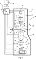
- Fig. 4 shows an embodiment of the storage apparatus L.
- the top row of Fig. 4 shows how samples S are loaded into the storage apparatus L.
- samples are provided in gridboxes G.
- the gridboxes are placed inside a housing 201 of the storage apparatus L, wherein said housing 201 is partly filled with liquid nitrogen 203.
- a cassette C is provided in the liquid nitrogen 203 as well.
- the samples are then manually transferred (step 1.) from the gridbox G to the cassette C.
- the cassette C remains (step 2.) inside the housing of the storage apparatus L.
- the cassette C may be moved, such as for example using cassette arm 211 (see bottom part of Fig. 4 ), to a separate storage location of the storage apparatus (not shown).
- the cassette C with samples S is stored inside the housing 201 of the storage apparatus L.
- the housing 201 with liquid nitrogen 203 provides a cryogenic storage room for safely storing the samples inside the storage apparatus.
- a transfer device T as defined herein is provided, and said transfer device T is connected to the storage apparatus S.
- the transfer device T comprises a housing 303 that is filled with gaseous nitrogen 303, in which a sample S to be transferred can be temporarily stored at the right temperature.
- the transfer device T comprises a transfer arm 311 with a gripper 331.
- the gripper 331 may be used for collecting a sample S.
- the gripper with the sample S may then be moved inside the housing 303 of the transfer device T.
- the storage apparatus L comprises a valve member 215.
- the transfer device T also comprises a valve member 315.
- the storage apparatus comprises a first docking member 221 that is arranged to mate with a second docking member 321 of the transfer device T (shown schematically).
- the storage apparatus may comprise a slot 221, and a housing part 321 of the transfer device may slide into said slot 221 for providing a connected state of the transfer device T and the storage apparatus. This way, a translational docking is provided.
- Other docking mechanisms or ways of connecting the transfer device T to the storage apparatus L are conceivable as well. It is advantageous in case the docking member 321 of the transfer device T acts as a male connector 321, and the docking member 221 of the storage apparatus L acts as a female connector 221.
- the valve 315 of the transfer device T is opened, and the valve of the storage apparatus 215 is opened as well.
- the cassette arm 211 positions the desired sample S in line with the transfer arm 311 of the transfer device T.
- the transfer arm 311 moves inside the housing 201 of the storage apparatus L, and picks the sample S out of the cassette C, using the gripper 331.
- the transfer device T is thus arranged for acquiring a sample S out of said cassette C.
- the gripper 331 with the sample S is then moved to the inside of the housing 303 of the transfer device T. All valves 215, 315 are then closed.
- the transfer device T can then be disconnected from the storage apparatus L, for movement to the Charged Particle apparatus.
- Fig. 4 Indicated in Fig. 4 , is that the step of positioning the desired sample S, using cassette arm 211, is done mechanically, and in particular automatically, without handling being required by a human operator.
- the human operator may, through a user interface, select the desired sample, but movement, positioning, collection and transfer are done automatically. This limits the possibility of errors that can occur.
- Fig. 5 shows the transfer device T in a disconnected state, wherein the sample S is safely seated in gripper 331 of the transfer arm 311.
- the sample is housed inside housing 303, wherein the housing is filled with gaseous nitrogen to keep the sample at a desired, low, temperature.
- the heat capacity of the gaseous cold nitrogen inside the housing 303 is such that the transfer device keeps the sample at a desired temperature range for several minutes, such as, for example 15 minutes.
- Additional cooling means may be provided on, or inside of, the transfer device T to provide active cooling of the sample S inside the housing 331.
- the transfer device T is transportable by a human operator.
- the dimensions of the transport device T are chosen such that the average human operator is able to carry the transport device from a first location to a second location, such as for example from the storage apparatus L to the charged particle microscope M.
- the device may have a length in the order of centimetres, decimetres, or even metres. In a practical embodiment, the device T has a length in between 40 cm to 80 cm, although other dimensions are conceivable as well.
- the weight of the device T may be in the order of 1 to several kilograms.
- Fig. 6 shows the transfer device T being connected to a microscope M.
- the microscope M is provided with a first docking member 421 that is able to mate with the second docking member 321 of the transport device T.
- the docking member 321 of the transport device T may be formed by an external housing part of the transport device T.
- the microscope M may be provided with a slot 421 that is able to receive the transport device T, or at least the second docking member thereof 321.
- the microscope M has a valve member 415. Once the transport device T is connected to the microscope M, or charged particle apparatus CPA in general, the valves 315, 415 can be opened, and the transfer arm 311 can move inside the microscope for transferring the sample S to the holder H of the microscope M. With this, the transfer of the sample from a storage location to the charged particle apparatus, such as an electron microscope M, is complete.
- the charged particle apparatus such as an electron microscope M
- the transfer device T can be removed from the microscope M, and transfer of a second sample S2 may occur, whilst the microscope is examining the first sample S.
- Fig. 7a-7f schematically show the sample handling and storage system 500 as defined herein.
- Fig. 7a shows that the system 500 comprises a storage apparatus L for storing a plurality of samples S, S2.
- the storage apparatus L may comprise a user input device 114, in the form of a conventional personal computer having a screen, for example.
- the system further comprises a Charged Particle Apparatus (CPA) M, such as a SEM, TEM, STEM and/or FIB.
- CPA Charged Particle Apparatus
- the CPA M is positioned at a location remote from said storage apparatus L. This means, in an embodiment that the CPA M is positioned at a distance of at least 50 cm from the storage apparatus L. For example, the CPA may be positioned at a distance of one to several metres from the storage apparatus.
- the distance between the storage apparatus L and the Charged Particle Apparatus M is so large, that a direct transfer from the storage apparatus L to the Apparatus M is not possible, and that an intermediate transfer step is necessary.
- the advantage of such a system is that it is relatively flexible, as the storage apparatus L and the charged particle apparatus can be positioned at any desirable location, even in different rooms with different environmental conditions.
- the system 500 comprises a transfer device T.
- the transfer device T can be handled by a human operator 600.
- the human operator 600 may carry the transfer device T to and from the storage device, and to and from the charged particle apparatus CPA M.
- the transfer device T is releasably connectable to said storage apparatus L.
- the transfer device is arranged for acquiring a CCP sample S from said plurality of CCP samples S, S2 when connected to said storage apparatus L.
- the transfer device T is connected to the storage apparatus L, for example by inserting the transfer device T in a slot that is present in the storage apparatus.
- the sample transfer as described in Fig. 4 can take place.
- the sample is moved from the storage apparatus L to the transfer device T, in a docked position of the transfer device T with respect to said storage apparatus L.
- Sample transfer from the storage apparatus L to the transfer device T takes place automatically, in an embodiment, without the need of human operator sample handling.
- the human operator may retrieve the transfer device T from the storage apparatus L.
- the transfer device T with the desired sample S can then be moved to a further location, such as the microscope.
- the human operator 600 may walk to the further location, wherein the transfer device T is carried by the human operator 600.
- Fig. 7e it is shown that the transfer device T with the sample S is connected to the microscope M (or charged particle apparatus in general).
- the transfer mechanism of the transfer device T then transfers the sample S from the transfer device T to the sample holder H of the microscope M.
- the sample can be observed and/or examined by the microscope M, as described with respect to Fig. 1 and Fig. 2 .
- the transfer device T comprises a transfer mechanism 311, 331 that is arranged for acquiring said CCP sample S from said storage apparatus L when connected to said storage apparatus L, and for delivering said CCP sample to said CPA when connected to said CPA.
- a single mechanism can be used to transfer the sample between two external apparatuses.
- the apparatuses do not need to have such a mechanism, although they should be arranged to cooperate with the transfer mechanism.
- the apparatuses may comprise additional measures, including mechanical arms 211, valves 215, 415 and the like, for optimizing sample transfer and cooperation with the transfer mechanism 311, 331 of the transfer device.
- the transfer mechanism comprises an movable arm 311.
- the movable arm may be arranged for translational movement.
- An outer end of the movable arm 311 may be provided with a gripper 331, wherein said gripper 331 is arranged for gripping and releasing a sample, in particular a sample that comprises a specimen that is provided on a specimen grid.
- the specimen grid may be connected to other grid elements as well, wherein these grid elements aid in the ease of handling of the sample.
- the grid elements may comprise, for example, a C-clip ring (i.e. AutoGrid, Thermo Fisher Scientific TM ) onto which the specimen grid can be mounted, and a C-clip for securing the specimen grid inside the C-clip ring.
- Other grids are, of course, conceivable as well.
- the storage apparatus L comprises an operator input device 114 in the form of a computer, and a control unit 220 that is connected to said operator input device 114 and that is arranged for performing at least some functions of said storage apparatus L, or of said system 500, for example in a connected state of said transfer device T to said storage apparatus L.
- the operator input device is, in an embodiment, arranged for selecting a CCP sample S, S2 to be transferred, by a human operator 600, from the storage apparatus to the charged particle microscope M.
- the control unit 220 is arranged for controlling said storage apparatus L and said transfer device T, in a connected state thereof, for transferring said selected CCP sample S from said storage apparatus L to said transfer device T.
- the storage apparatus L including the operator input device 114 may form a first workstation, that enables the human operator to quickly and reliably transfer prepared samples to the storage apparatus L.
- a top part of the housing 201 of the storage apparatus L may coincide with a desk feature of the workstation.
- the top part of the housing 201, and/or a desk feature of the workstation may comprise a lid that is openable and closable by a human operator, such that a gridbox G containing samples S (see Fig. 4 , step 1.) can be inserted into the storage apparatus L, and the sample grids S can be transferred to the container C.
- the lid may also be used for refilling the liquid nitrogen level 203 inside the housing 201.
- the operator input device and/or the controller may be connected to the housing 201, so that information relating to the housing 201 may be provided to the human operator.
- the storage apparatus may comprise a number of sensor elements, such as a temperature sensor, a liquid level sensor, or the like, for monitoring a condition of the storage apparatus.
- the operator input device 114 may provide feedback to the user with respect to one or more of these conditions.
- the operator input device 114 is used for labelling and tracking features.
- the operator input device 114 may be wirelessly connected to the Charged Particle Apparatus, so that information regarding the sample S can be transferred to the Charged Particle Apparatus.
- Information may comprise sample input information, e.g. information that the human operator enters into the operator input device 114 at the time of loading a sample S into a cassette C.
Landscapes
- Chemical & Material Sciences (AREA)
- Analytical Chemistry (AREA)
- General Health & Medical Sciences (AREA)
- Life Sciences & Earth Sciences (AREA)
- Health & Medical Sciences (AREA)
- Biochemistry (AREA)
- Physics & Mathematics (AREA)
- General Physics & Mathematics (AREA)
- Immunology (AREA)
- Pathology (AREA)
- Analysing Materials By The Use Of Radiation (AREA)
- Sampling And Sample Adjustment (AREA)
- Apparatus Associated With Microorganisms And Enzymes (AREA)
Priority Applications (4)
| Application Number | Priority Date | Filing Date | Title |
|---|---|---|---|
| EP20208366.3A EP4002419A1 (de) | 2020-11-18 | 2020-11-18 | System und verfahren zur handhabung von kryoproben für ladungsträgerteilchen-instrumente |
| US17/523,246 US11802823B2 (en) | 2020-11-18 | 2021-11-10 | System and method for handling cryo-charged particle samples |
| CN202111362600.9A CN114544683A (zh) | 2020-11-18 | 2021-11-17 | 用于处理低温带电粒子样本的系统和方法 |
| JP2021187305A JP7622328B2 (ja) | 2020-11-18 | 2021-11-17 | 低温荷電粒子試料を取り扱うためのシステムおよび方法 |
Applications Claiming Priority (1)
| Application Number | Priority Date | Filing Date | Title |
|---|---|---|---|
| EP20208366.3A EP4002419A1 (de) | 2020-11-18 | 2020-11-18 | System und verfahren zur handhabung von kryoproben für ladungsträgerteilchen-instrumente |
Publications (1)
| Publication Number | Publication Date |
|---|---|
| EP4002419A1 true EP4002419A1 (de) | 2022-05-25 |
Family
ID=73475990
Family Applications (1)
| Application Number | Title | Priority Date | Filing Date |
|---|---|---|---|
| EP20208366.3A Pending EP4002419A1 (de) | 2020-11-18 | 2020-11-18 | System und verfahren zur handhabung von kryoproben für ladungsträgerteilchen-instrumente |
Country Status (4)
| Country | Link |
|---|---|
| US (1) | US11802823B2 (de) |
| EP (1) | EP4002419A1 (de) |
| JP (1) | JP7622328B2 (de) |
| CN (1) | CN114544683A (de) |
Families Citing this family (1)
| Publication number | Priority date | Publication date | Assignee | Title |
|---|---|---|---|---|
| US12553812B2 (en) * | 2021-09-13 | 2026-02-17 | Gregory Hirsch | Vacuum ultraviolet cryo-EM grid screening tool |
Citations (1)
| Publication number | Priority date | Publication date | Assignee | Title |
|---|---|---|---|---|
| WO2020119956A1 (en) * | 2018-12-11 | 2020-06-18 | Ferrovac Gmbh | Cryogenic ultra-high vacuum suitcase |
Family Cites Families (5)
| Publication number | Priority date | Publication date | Assignee | Title |
|---|---|---|---|---|
| DE102014110722B4 (de) | 2014-07-29 | 2016-06-09 | Leica Mikrosysteme Gmbh | Ladestation zum Umladen von gefrorenen Proben bei tiefen Temperaturen |
| DE102015100727A1 (de) | 2015-01-20 | 2016-07-21 | Leica Mikrosysteme Gmbh | Probentransfereinrichtung |
| NL2019247B1 (en) * | 2017-07-14 | 2019-01-28 | Hennyz B V | Cryotransfer system |
| EP4174903A1 (de) * | 2017-10-30 | 2023-05-03 | Gatan, Inc. | Kryotransferhalter und arbeitsstation |
| NL2020235B1 (en) * | 2018-01-05 | 2019-07-12 | Hennyz B V | Vacuum transfer assembly |
-
2020
- 2020-11-18 EP EP20208366.3A patent/EP4002419A1/de active Pending
-
2021
- 2021-11-10 US US17/523,246 patent/US11802823B2/en active Active
- 2021-11-17 JP JP2021187305A patent/JP7622328B2/ja active Active
- 2021-11-17 CN CN202111362600.9A patent/CN114544683A/zh active Pending
Patent Citations (1)
| Publication number | Priority date | Publication date | Assignee | Title |
|---|---|---|---|---|
| WO2020119956A1 (en) * | 2018-12-11 | 2020-06-18 | Ferrovac Gmbh | Cryogenic ultra-high vacuum suitcase |
Non-Patent Citations (1)
| Title |
|---|
| SEBASTIAN TACKE ET AL: "A Versatile High-Vacuum Cryo-transfer System for Cryo-microscopy and Analytics", BIOPHYSICAL JOURNAL, vol. 110, no. 4, 1 February 2016 (2016-02-01), AMSTERDAM, NL, pages 758 - 765, XP055564876, ISSN: 0006-3495, DOI: 10.1016/j.bpj.2016.01.024 * |
Also Published As
| Publication number | Publication date |
|---|---|
| JP2022080890A (ja) | 2022-05-30 |
| US11802823B2 (en) | 2023-10-31 |
| CN114544683A (zh) | 2022-05-27 |
| JP7622328B2 (ja) | 2025-01-28 |
| US20220155193A1 (en) | 2022-05-19 |
Similar Documents
| Publication | Publication Date | Title |
|---|---|---|
| US11251014B2 (en) | Sample holder for a charged particle microscope | |
| US9741527B2 (en) | Specimen holder for a charged particle microscope | |
| Mills | Setting up and operating a cryo-EM laboratory | |
| KR20150016349A (ko) | 하전 입자선 장치 | |
| KR20150016350A (ko) | 관찰 장치 및 광축 조정 방법 | |
| US12431322B2 (en) | System and method for handling samples for study in a charged particle apparatus, such as a transmission electron microscope | |
| US11802823B2 (en) | System and method for handling cryo-charged particle samples | |
| US11127560B2 (en) | Charged particle microscope with a manipulator device, and method of preparing a specimen with said charged particle microscope | |
| US20240047172A1 (en) | Clamping mechanism | |
| EP3401943B1 (de) | Innovative bildverarbeitung in der ladungsteilchenmikroskopie | |
| US20230296639A1 (en) | Cryogenic sample handling and storage system | |
| EP3647763B1 (de) | Verfahren zur herstellung einer biologischen probe zur untersuchung in einer analysevorrichtung | |
| US10699875B2 (en) | Confocal imaging technique in a charged particle microscope | |
| US10651007B2 (en) | Cryogenic cell for mounting a specimen in a charged particle microscope | |
| EP4607570A1 (de) | Probenspitze | |
| US20240161999A1 (en) | Laser Thermal Epitaxy in a Charged Particle Microscope | |
| US12525427B2 (en) | Transmission charged particle beam apparatus, and method of aligning such a transmission charged particle beam apparatus | |
| US12463009B2 (en) | Method and system for studying samples using a scanning transmission charged particle microscope with reduced beam induced sample damage | |
| US20240027377A1 (en) | Method of examining a sample using a charged particle microscope | |
| EP3147929A1 (de) | Ladungsträgerteilchenmikroskop mit verbesserter spektroskopischer funktionalität |
Legal Events
| Date | Code | Title | Description |
|---|---|---|---|
| PUAI | Public reference made under article 153(3) epc to a published international application that has entered the european phase |
Free format text: ORIGINAL CODE: 0009012 |
|
| STAA | Information on the status of an ep patent application or granted ep patent |
Free format text: STATUS: THE APPLICATION HAS BEEN PUBLISHED |
|
| AK | Designated contracting states |
Kind code of ref document: A1 Designated state(s): AL AT BE BG CH CY CZ DE DK EE ES FI FR GB GR HR HU IE IS IT LI LT LU LV MC MK MT NL NO PL PT RO RS SE SI SK SM TR |
|
| STAA | Information on the status of an ep patent application or granted ep patent |
Free format text: STATUS: REQUEST FOR EXAMINATION WAS MADE |
|
| 17P | Request for examination filed |
Effective date: 20221122 |
|
| RBV | Designated contracting states (corrected) |
Designated state(s): AL AT BE BG CH CY CZ DE DK EE ES FI FR GB GR HR HU IE IS IT LI LT LU LV MC MK MT NL NO PL PT RO RS SE SI SK SM TR |
|
| STAA | Information on the status of an ep patent application or granted ep patent |
Free format text: STATUS: EXAMINATION IS IN PROGRESS |
|
| 17Q | First examination report despatched |
Effective date: 20240726 |