EP4002524B1 - Brennstoffzellenstapel - Google Patents
Brennstoffzellenstapel Download PDFInfo
- Publication number
- EP4002524B1 EP4002524B1 EP20843516.4A EP20843516A EP4002524B1 EP 4002524 B1 EP4002524 B1 EP 4002524B1 EP 20843516 A EP20843516 A EP 20843516A EP 4002524 B1 EP4002524 B1 EP 4002524B1
- Authority
- EP
- European Patent Office
- Prior art keywords
- passage portion
- gas
- passages
- opposing
- passage
- Prior art date
- Legal status (The legal status is an assumption and is not a legal conclusion. Google has not performed a legal analysis and makes no representation as to the accuracy of the status listed.)
- Active
Links
Images




Classifications
-
- H—ELECTRICITY
- H01—ELECTRIC ELEMENTS
- H01M—PROCESSES OR MEANS, e.g. BATTERIES, FOR THE DIRECT CONVERSION OF CHEMICAL ENERGY INTO ELECTRICAL ENERGY
- H01M8/00—Fuel cells; Manufacture thereof
- H01M8/24—Grouping of fuel cells, e.g. stacking of fuel cells
-
- H—ELECTRICITY
- H01—ELECTRIC ELEMENTS
- H01M—PROCESSES OR MEANS, e.g. BATTERIES, FOR THE DIRECT CONVERSION OF CHEMICAL ENERGY INTO ELECTRICAL ENERGY
- H01M8/00—Fuel cells; Manufacture thereof
- H01M8/02—Details
- H01M8/0202—Collectors; Separators, e.g. bipolar separators; Interconnectors
- H01M8/0258—Collectors; Separators, e.g. bipolar separators; Interconnectors characterised by the configuration of channels, e.g. by the flow field of the reactant or coolant
- H01M8/026—Collectors; Separators, e.g. bipolar separators; Interconnectors characterised by the configuration of channels, e.g. by the flow field of the reactant or coolant characterised by grooves, e.g. their pitch or depth
-
- H—ELECTRICITY
- H01—ELECTRIC ELEMENTS
- H01M—PROCESSES OR MEANS, e.g. BATTERIES, FOR THE DIRECT CONVERSION OF CHEMICAL ENERGY INTO ELECTRICAL ENERGY
- H01M8/00—Fuel cells; Manufacture thereof
- H01M8/02—Details
- H01M8/0271—Sealing or supporting means around electrodes, matrices or membranes
- H01M8/0273—Sealing or supporting means around electrodes, matrices or membranes with sealing or supporting means in the form of a frame
-
- H—ELECTRICITY
- H01—ELECTRIC ELEMENTS
- H01M—PROCESSES OR MEANS, e.g. BATTERIES, FOR THE DIRECT CONVERSION OF CHEMICAL ENERGY INTO ELECTRICAL ENERGY
- H01M8/00—Fuel cells; Manufacture thereof
- H01M8/02—Details
- H01M8/0271—Sealing or supporting means around electrodes, matrices or membranes
- H01M8/0276—Sealing means characterised by their form
-
- H—ELECTRICITY
- H01—ELECTRIC ELEMENTS
- H01M—PROCESSES OR MEANS, e.g. BATTERIES, FOR THE DIRECT CONVERSION OF CHEMICAL ENERGY INTO ELECTRICAL ENERGY
- H01M8/00—Fuel cells; Manufacture thereof
- H01M8/24—Grouping of fuel cells, e.g. stacking of fuel cells
- H01M8/2404—Processes or apparatus for grouping fuel cells
-
- H—ELECTRICITY
- H01—ELECTRIC ELEMENTS
- H01M—PROCESSES OR MEANS, e.g. BATTERIES, FOR THE DIRECT CONVERSION OF CHEMICAL ENERGY INTO ELECTRICAL ENERGY
- H01M2250/00—Fuel cells for particular applications; Specific features of fuel cell system
- H01M2250/10—Fuel cells in stationary systems, e.g. emergency power source in plant
-
- H—ELECTRICITY
- H01—ELECTRIC ELEMENTS
- H01M—PROCESSES OR MEANS, e.g. BATTERIES, FOR THE DIRECT CONVERSION OF CHEMICAL ENERGY INTO ELECTRICAL ENERGY
- H01M8/00—Fuel cells; Manufacture thereof
- H01M8/02—Details
- H01M8/0202—Collectors; Separators, e.g. bipolar separators; Interconnectors
- H01M8/0258—Collectors; Separators, e.g. bipolar separators; Interconnectors characterised by the configuration of channels, e.g. by the flow field of the reactant or coolant
- H01M8/0265—Collectors; Separators, e.g. bipolar separators; Interconnectors characterised by the configuration of channels, e.g. by the flow field of the reactant or coolant the reactant or coolant channels having varying cross sections
-
- H—ELECTRICITY
- H01—ELECTRIC ELEMENTS
- H01M—PROCESSES OR MEANS, e.g. BATTERIES, FOR THE DIRECT CONVERSION OF CHEMICAL ENERGY INTO ELECTRICAL ENERGY
- H01M8/00—Fuel cells; Manufacture thereof
- H01M8/02—Details
- H01M8/0202—Collectors; Separators, e.g. bipolar separators; Interconnectors
- H01M8/0267—Collectors; Separators, e.g. bipolar separators; Interconnectors having heating or cooling means, e.g. heaters or coolant flow channels
-
- Y—GENERAL TAGGING OF NEW TECHNOLOGICAL DEVELOPMENTS; GENERAL TAGGING OF CROSS-SECTIONAL TECHNOLOGIES SPANNING OVER SEVERAL SECTIONS OF THE IPC; TECHNICAL SUBJECTS COVERED BY FORMER USPC CROSS-REFERENCE ART COLLECTIONS [XRACs] AND DIGESTS
- Y02—TECHNOLOGIES OR APPLICATIONS FOR MITIGATION OR ADAPTATION AGAINST CLIMATE CHANGE
- Y02E—REDUCTION OF GREENHOUSE GAS [GHG] EMISSIONS, RELATED TO ENERGY GENERATION, TRANSMISSION OR DISTRIBUTION
- Y02E60/00—Enabling technologies; Technologies with a potential or indirect contribution to GHG emissions mitigation
- Y02E60/30—Hydrogen technology
- Y02E60/50—Fuel cells
Definitions
- the present disclosure relates to a fuel cell stack.
- Polymer electrolyte fuel cells include a fuel cell stack that includes stacked cells (see, for example, Patent Document 1).
- Each cell disclosed in Patent Document 1 includes a power generation portion including a membrane electrode assembly, two separators that hold the power generation portion, and a gas passage defining plate disposed between the power generation portion and the two separators.
- the gas passage defining plate includes recesses and projections that are alternately arranged.
- the gas passage defining plate also includes a gas passage portion including a mesh-shaped part defined by the recesses and the projections and by the power generation portion.
- Reactant gas such as fuel gas or oxidant gas, flows through the gas passage portion.
- Each cell has a rectangular shape in plan view.
- a fuel gas supply port through which fuel gas is supplied and a fuel gas discharge port through which fuel gas is discharged are respectively disposed at the opposite ends of the power generation portion on the short sides of the cell.
- Oxidant gas supply ports through which oxidant gas is supplied and oxidant gas discharge ports through which oxidant gas is discharged are respectively disposed at the opposite ends of the power generation portion on the long sides of the cell.
- the oxidant gas supply ports are spaced apart from each other in the longitudinal direction of the long sides of the cell.
- the oxidant gas discharge ports are spaced apart from each other in the longitudinal direction of the long sides of the cell.
- the oxidant gas supplied from the oxidant gas supply ports is supplied to the power generation portion through the gas passage portion of the gas passage defining plate.
- the oxidant gas electrochemically reacts with the fuel gas so as to generate power.
- the oxidant gas that has not been used to generate power in the power generation portion is discharged out of the oxidant gas discharge ports through the gas passage portion.
- Patent Document 1 Japanese Laid-Open Patent Publication No. 2016-21339
- reactant gas be diffused over a wider range of the power generation portion (i.e., over a wider range of the gas passage portion).
- a partition is disposed between adjacent ones of the oxidant gas supply ports to divide the oxidant gas supply ports from each other.
- the oxidant gas flowing from the oxidant gas supply ports through the gas passage portion toward the oxidant gas discharge ports does not easily flow to a portion adjacent to each partition. Accordingly, there is room for improvement to allow reactant gas to be diffused over a wider range of the gas passage portion (i.e., to improve the performance of distributing reactant gas).
- a fuel cell stack that achieves the above-described objective includes stacked cells.
- Each cell includes a sheet-shaped power generation portion, two separators that hold the power generation portion in a thickness direction, a gas passage defining plate disposed between at least one of the two separators and the power generation portion, the gas passage defining plate including a gas passage portion through which reactant gas flows, and a frame member disposed around the gas passage defining plate, the frame member including a supply port through which the reactant gas is supplied to the gas passage portion and a discharge port through which the reactant gas is discharged from the gas passage portion.
- a flow direction of the reactant gas flowing from the supply port toward the discharge port is referred to as a flow direction.
- the main passages of the second passage portion each have a larger cross-sectional flow area than the main passages of the first passage portion.
- each of the opposing portions defining the main passages of the second passage portion is larger than the width of the corresponding one of the opposing portions defining the main passages of the first passage portion.
- the main passages of the second passage portion each have a larger cross-sectional flow area than the main passages of the first passage portion.
- the gas passage portion include a third passage portion that is adjacent to the first passage portion on a downstream side in the flow direction and that the main passages of the second third passage portion each have a smaller cross-sectional flow area than the main passages of the first passage portion.
- the opposing portions defining the main passages of the third passage portion are closer to the power generation portion in the opposing direction than the opposing portions defining the main passages of the first passage portion.
- the main passages of the third passage portion each have a smaller cross-sectional flow area than the main passages of the first passage portion.
- the main passages of the third passage portion each have a smaller cross-sectional flow area than the main passages of the first passage portion.
- each of the opposing portions of the first passage portion be made continuous with a corresponding one of the opposing portions of the third passage portion by a step.
- This structure causes the reactant gas flowing in the flow direction to collide with the steps.
- the pressure drop of reactant gas easily increases at the boundary between the first passage portion and the third passage portion. This increases the difference in pressure drop of reactant gas between the first passage portion and the third passage portion.
- the gas passage portion include wavy portions that are integrally disposed on opposite sides of each of the opposing portions in the orthogonal direction, the wavy portions each having a wavy cross-sectional shape that is orthogonal to the orthogonal direction. It is preferred that each of the wavy portions include first projections and second projections, the first projections protruding closer to the power generation portion than the opposing portions and being in contact with the power generation portion, the second projections protruding closer to a corresponding one of the separators than the opposing portions and being in contact with the separators, and the first projections and the second projections being alternately arranged in the flow direction. It is preferred that each of the connection passages be defined by the first projections and the opposing portions. It is preferred that the connection passages of the second passage portion each have a larger cross-sectional flow area than the connection passages of the first passage portion.
- connection passages of the second passage portion each have a larger cross-sectional flow area than the connection passages of the first passage portion.
- the reactant gas in the connection passages of the second passage portion causes a smaller pressure drop than the reactant gas in the connection passages of the first passage portion. Accordingly, the reactant gas that has flowed from each of the supply ports to the first passage portion easily flows to the second passage portion through the connection passages of the second passage portion. That is, the reactant gas that has flowed from each of the supply ports easily flows from the first passage portion toward the second passage portion. Accordingly, the performance of distributing reactant gas further improves.
- the gas passage portion include a third passage portion that is adjacent to the first passage portion on a downstream side in the flow direction and the connection passages of the third passage portion each have a smaller cross-sectional flow area than the connection passages of the first passage portion.
- connection passages of the third passage portion each have a smaller cross-sectional flow area than the connection passages of the first passage portion.
- the reactant gas in the connection passages of the third passage portion causes a larger pressure drop than the reactant gas in the connection passages of the first passage portion. Accordingly, the reactant gas that has flowed from each of the supply ports to the first passage portion flows to the second passage portion through the connection passages of the second passage portion more easily than to the connection passages of the third passage portion. Accordingly, the performance of distributing reactant gas further improves.
- the fuel cell stack according to the present disclosure improves the performance of distributing reactant gas.
- a frame member 60 is disposed around the gas passage defining plate 50.
- the frame member 60 is made of plastic and has the shape of a substantially rectangular plate in plan view.
- the MEGA 20 and the gas passage defining plate 50 that are overlapped with each other are fitted to the frame member 60 of the present embodiment.
- the frame member 60 is held by the first separator 30 and the second separator 40 in the thickness direction.
- the frame member 60 includes a fuel gas supply port 12 through which fuel gas is supplied as reactant gas and a fuel gas discharge port 13 through which fuel gas is discharged.
- the fuel gas supply port 12 and the fuel gas discharge port 13 are respectively located on the opposite sides of the gas passage defining plate 50 in the left-right direction.
- the fuel gas in the present embodiment is, for example, hydrogen gas.
- the fuel gas supply port 12 is located on the left of the gas passage defining plate 50 at a position closer to the upper side of the gas passage defining plate 50 than the middle of the gas passage defining plate 50 in the up-down direction.
- the fuel gas discharge port 13 is located on the right of the gas passage defining plate 50 at a position closer to the lower side of the gas passage defining plate 50 than the middle of the gas passage defining plate 50 in the up-down direction.
- the oxidant gas supplied from the oxidant gas supply ports 16 flows to the gas passage defining plate 50 and is then discharged out of the oxidant gas discharge ports 17.
- the MEGA 20 includes a membrane electrode assembly 21, an anode-side gas diffusion layer 24, and a cathode-side gas diffusion layer 25.
- the membrane electrode assembly 21 includes an electrolyte membrane 22 and two catalytic electrode layers 23 that hold the electrolyte membrane 22.
- the electrolyte membrane 22 is made of a solid polymer material that has an excellent proton conductivity in a wet state.
- Each catalytic electrode layer 23 supports a catalyst, such as platinum, in order to expedite the electrochemical reaction of reactant gas in the fuel cell.
- the first separator 30 is formed by pressing a metal (e.g., stainless steel) plate.
- the middle portion of the first separator 30 is in contact with the anode-side gas diffusion layer 24 of the MEGA 20.
- the portion located outward from the middle portion of the first separator 30 is in contact with the frame member 60.
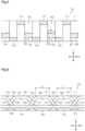
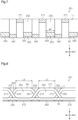
- the length of the first passage portion 151 in the orthogonal direction Z is substantially equal to the length of each oxidant gas supply port 16 in the orthogonal direction Z.
- the length of the second passage portion 251 in the orthogonal direction Z is substantially equal to the length of each partition 18 in the orthogonal direction Z.
- the length of the third passage portion 351 in the orthogonal direction Z is substantially equal to the length of the first passage portion 151 in the orthogonal direction Z.
- the length of the first passage portion 151 in the flow direction X is substantially equal to the length of the second passage portion 251 in the flow direction X.
- the first passage portion 151 includes opposing portions 160 that oppose the power generation portion 11.
- the opposing portions 160 extend in the flow direction X and are arranged in parallel in the orthogonal direction Z.
- Each opposing portion 160 has the shape of a substantially quadrilateral bar.
- Fig. 3 is a perspective view showing the first passage portion 151 having the basic shape of the gas passage portion 51.
- Wavy portions 170, 180 are integrally disposed on the opposite sides of each opposing portion 160 in the orthogonal direction Z.
- the wavy portions 170, 180 each have a wavy cross-sectional shape that is orthogonal to the orthogonal direction Z.
- the wavy portions 170, 180 have the same shape. Thus, only the structure of the wavy portion 170 will be hereinafter described.
- the components of the wavy portion 180 are given reference number 18*, which is obtained by adding 10 to reference number 17* of the wavy portion 170, and redundant description will not be made.
- the wavy portions 170 and the wavy portions 180 are disposed adjacent to each other in the orthogonal direction Z such that the first projections 171 are adjacent to second projections 182 in the orthogonal direction Z and the second projections 172 are adjacent to first projections 181 in the orthogonal direction Z.
- a main passage 152 is defined between each opposing portion 160 and the power generation portion 11.
- the oxidant gas supplied from the oxidant gas supply ports 16 flows through the main passages 152.
- the main passages 152 are defined in correspondence with the opposing portions 160 and thus arranged in parallel in the orthogonal direction Z.
- the cross-sectional flow area of each main passage 152 hereinafter refers to the cross-sectional flow area of each main passage 152 on a plane that is orthogonal to the flow direction X.
- a water passage 153 is defined between each opposing portion 160 and the second separator 40. Generated water that is generated through the electrochemical reaction in the power generation portion 11 flows through the water passages 153.
- the first passage portion 151 includes connection passages 154 that each connect the main passages 152 to each other.
- the connection passages 154 are spaced apart from each other in the flow direction X.
- the connection passages 154 are defined by the first projections 171, 181 of the wavy portions 170, 180 and by the opposing portions 160 on a plane that is orthogonal to the orthogonal direction Z.
- a sub-passage 155 is defined between two of the connection passages 154 adjacent to each other in the flow direction X. Each sub-passage 155 connects these two connection passages 154 to each other.
- the sub-passages 155 are defined by the first projections 171 and the first projections 181 (more specifically, by inclined portions 173 and inclined portions 183) of the wavy portion 170 and the wavy portion 180 adjacent to each other and by the power generation portion 11 on the plane that is orthogonal to the orthogonal direction Z.
- connection passages 254 of the second passage portion 251 each have a larger cross-sectional flow area than the connection passages 154 of the first passage portion 151.
- the main passages 252 of the second passage portion 251 each have a larger cross-sectional flow area than the main passages 152 of the first passage portion 151.
- the oxidant gas in the main passages 252 of the second passage portion 251 causes a smaller pressure drop than the oxidant gas in the main passages 152 of the first passage portion 151. Accordingly, as shown by arrow A in Fig. 12 , the oxidant gas that has flowed from the oxidant gas supply port 16 to the main passages 152 of the first passage portion 151 easily flows to the main passages 252 of the second passage portion 251 through the connection passages 154 (operation 1).
- the main passages 352 of the third passage portion 351 each have a smaller cross-sectional flow area than the main passages 152 of the first passage portion 151.
- the oxidant gas in the main passages 352 of the third passage portion 351 causes a larger pressure drop than the oxidant gas in the main passages 152 of the first passage portion 151.
- the oxidant gas flowing from the oxidant gas supply port 16 to the main passages 152 of the first passage portion 151 flows to the second passage portion 251, which have a relatively small pressure drop, more easily than through the third passage portion 351, which have a relatively large pressure drop (operation 2).
- connection passages 254 of the second passage portion 251 each have a larger cross-sectional flow area than the connection passages 154 of the first passage portion 151.
- the oxidant gas in the connection passages 254 of the second passage portion 251 causes a smaller pressure drop than the oxidant gas in the connection passages 154 of the first passage portion 151. Accordingly, as shown by arrow A in Fig. 12 , the oxidant gas that has flowed from each of the oxidant gas supply ports 16 to the first passage portion 151 easily flows to the second passage portion 251 through the connection passages 254 of the second passage portion 251. That is, the oxidant gas that has flowed from each of the oxidant gas supply ports 16 easily flows from the first passage portion 151 toward the second passage portion 251 (operation 3).
- the opposing portions 260 defining the main passages 252 of the second passage portion 251 are farther from the power generation portion 11 in the opposing direction Y than the opposing portions 160 defining the main passages 152 of the first passage portion 151.
- the main passages 252 of the second passage portion 251 each have a larger cross-sectional flow area than the main passages 152 of the first passage portion 151.
- Such a structure causes the reactant gas flowing in the flow direction X to collide with the steps 52.
- the pressure drop of oxidant gas easily increases at the boundary between the first passage portion 151 and the third passage portion 351. This increases the difference in pressure drop of oxidant gas between the first passage portion 151 and the third passage portion 351.
- Such a structure produces the above-described operation 3 and thus further improves the performance of distributing oxidant gas.
- connection passages 354 of the third passage portion 351 each have a smaller cross-sectional flow area than the connection passages 154 of the first passage portion 151.
- Such a structure produces the above-described operation 4 and thus further improves the performance of distributing oxidant gas.
- the present embodiment may be modified as follows.
- the present embodiment and the following modifications can be combined as long as they remain technically consistent with each other.
- the third passage portion 351 may be adjacent to the first passage portion 151 and the second passage portion 251 on the downstream side in the flow direction X. This limits the flow of oxidant gas from the second passage portion 251 toward the third passage portion 351 and thus allows the oxidant gas to easily flow in the orthogonal direction Z.
- the gas passage portion 51 may include second passage portions 251 that are adjacent to the opposite sides of each first passage portion 151 in the orthogonal direction Z.
- the sub-passages 155 of the first passage portion 151 each have the same cross-sectional flow area as the sub-passages 255 of the second passage portion 251.
- the sub-passages 255 may each have a larger cross-sectional flow area than the sub-passages 155.
- the oxidant gas in the sub-passages 255 of the second passage portion 251 causes a smaller pressure drop than the oxidant gas in the sub-passages 155 of the first passage portion 151. Accordingly, the oxidant gas flowing from the oxidant gas supply ports 16 to the first passage portion 151 easily flows to the second passage portion 251 through the sub-passages 255 of the second passage portion 251.
- the oxidant gas flowing from the oxidant gas supply ports 16 to the first passage portion 151 flows to the second passage portion 251 through the sub-passages 255 of the second passage portion 251 than through the sub-passages 355 of the third passage portion 351. That is, the oxidant gas that has flowed from the oxidant gas supply ports 16 easily flows from the first passage portion 151 toward the second passage portion 251. This allows the oxidant gas to be distributed over a wider range of the gas passage portion 51.
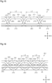
- Length L1 of the tops of the first projections 171, 181 of the first passage portion 151 may be equal to length L3 of the tops of the first projections 371, 381 of the third passage portion 351. Even in this case, the opposing portions 360 of the third passage portion 351 are closer to the power generation portion 11 in the opposing direction Y than the opposing portions 160 of the first passage portion 151. Thus, the main passages 352 of the third passage portion 351 each have a smaller cross-sectional flow area than the main passages 152 of the first passage portion 151. This provides the above-described advantage (4).
- the opposing portions 160, 260, 360 may be inclined so as to approach the power generation portion 11 in the opposing direction Y toward the downstream side in the flow direction X. In this case, the pressure drop of oxidant gas gradually increases toward the downstream side in the flow direction X.
- each opposing portion 360 of the third passage portion 351 from the power generation portion 11 is equal to the distance of the corresponding opposing portion 160 of the first passage portion 151 from the power generation portion 11, and length L3 of the tops of the first projections 371, 381 of the third passage portion 351 is equal to length L1 of the tops of the first projections 171, 181 of the first passage portion 151.
- the opposing portions 260 of the second passage portion 251 are farther from the power generation portion 11 in the opposing direction Y than the opposing portions 160 of the first passage portion 151, and width W2 of each opposing portion 260 is larger than width W1 of the corresponding opposing portion 160.
- length L2 of the tops of the first projections 271, 281 of the second passage portion 251 is longer than length L1 of the tops of the first projections 171, 181 of the first passage portion 151.
- the main passages 252 of the second passage portion 251 each have a larger cross-sectional flow area than the main passages 152 of the first passage portion 151. This provides the above-described advantages (1) to (3).
- width W2 of each opposing portion 260 may be equal to width W1 of the corresponding opposing portion 160.
- each opposing portion 260 of the second passage portion 251 is larger than width W1 of the corresponding opposing portion 160 of the first passage portion 151, the distance of the opposing portions 260 from the power generation portion 11 may be equal to the distance of the opposing portions 160 from the power generation portion 11.
- the gas passage defining plate 50 is located on the cathode side, to which oxidant gas is supplied. Instead, the gas passage defining plate 50 may be located on the anode side, to which fuel gas is supplied.
Landscapes
- Life Sciences & Earth Sciences (AREA)
- Engineering & Computer Science (AREA)
- Manufacturing & Machinery (AREA)
- Sustainable Development (AREA)
- Sustainable Energy (AREA)
- Chemical & Material Sciences (AREA)
- Chemical Kinetics & Catalysis (AREA)
- Electrochemistry (AREA)
- General Chemical & Material Sciences (AREA)
- Fuel Cell (AREA)
Claims (8)
- Brennstoffzellenstapel, der gestapelte Zellen aufweist, von denen jede enthält:einen blattförmigen Leistungserzeugungsabschnitt;zwei Separatoren, die den Leistungserzeugungsabschnitt in einer Dickenrichtung halten;eine einen Gasdurchgang definierende Platte, die zwischen zumindest einem der beiden Separatoren und dem Leistungserzeugungsabschnitt angeordnet ist, wobei die den Gasdurchgang definierende Platte einen Gasdurchgangsabschnitt, durch den Reaktionsgas strömt, enthält; undein Rahmenelement, das um die den Gasdurchgang definierende Platte herum angeordnet ist, wobei das Rahmenelement einen Zufuhranschluss, durch den das Reaktionsgas dem Gasdurchgangsabschnitt zugeführt wird, und einen Auslassanschluss, durch den das Reaktionsgas aus dem Gasdurchgangsabschnitt ausgelassen wird, enthält, wobeieine Strömungsrichtung des Reaktionsgases, das von dem Zufuhranschluss zu dem Auslassanschluss strömt, als Strömungsrichtung bezeichnet wird,eine Richtung, in der der Leistungserzeugungsabschnitt dem Gasdurchgangsabschnitt gegenüberliegt, als entgegengesetzte Richtung bezeichnet wird,eine Richtung, die orthogonal zu der Strömungsrichtung und zu der entgegengesetzten Richtung ist, als orthogonale Richtung bezeichnet wird,der Gasdurchgangsabschnitt gegenüberliegende Abschnitte, die sich in der Strömungsrichtung erstrecken und parallel in der orthogonalen Richtung angeordnet sind, enthält, wobei die gegenüberliegenden Abschnitte dem Leistungserzeugungsabschnitt gegenüberliegen,ein Hauptdurchgang zwischen jedem der gegenüberliegenden Abschnitte und dem Leistungserzeugungsabschnitt definiert ist,der Gasdurchgangsabschnitt Verbindungsdurchgänge, die jeweils die Hauptdurchgänge miteinander verbinden und in der Strömungsrichtung voneinander beabstandet sind, enthält,der Gasdurchgangsabschnitt einen ersten Durchgangsabschnitt und einen zweiten Durchgangsabschnitt enthält, wobei der erste Durchgangsabschnitt in der Strömungsrichtung zu dem Zufuhranschluss benachbart ist und der zweite Durchgangsabschnitt in der orthogonalen Richtung zu dem ersten Durchgangsabschnitt benachbart ist, unddie Hauptdurchgänge des zweiten Durchgangsabschnitts jeweils eine größere Strömungsquerschnittsfläche aufweisen als die Hauptdurchgänge des ersten Durchgangsabschnitts.
- Brennstoffzellenstapel nach Anspruch 1, wobei die gegenüberliegenden Abschnitte des zweiten Durchgangsabschnitts in der entgegengesetzten Richtung weiter von dem Leistungserzeugungsabschnitt entfernt sind als die gegenüberliegenden Abschnitte des ersten Durchgangsabschnitts.
- Brennstoffzellenstapel nach Anspruch 1 oder 2, wobei die gegenüberliegenden Abschnitte des zweiten Durchgangsabschnitts in der orthogonalen Richtung jeweils eine größere Breite aufweisen als die gegenüberliegenden Abschnitte des ersten Durchgangsabschnitts.
- Brennstoffzellenstapel nach einem der Ansprüche 1 bis 3, wobei der Gasdurchgangsabschnitt einen dritten Durchgangsabschnitt, der auf einer stromabwärts gelegenen Seite in der Strömungsrichtung zu dem ersten Durchgangsabschnitt benachbart ist, enthält, und die Hauptdurchgänge des dritten Durchgangsabschnitts jeweils eine kleinere Querschnittsströmungsfläche aufweisen als die Hauptdurchgänge des ersten Durchgangsabschnitts.
- Brennstoffzellenstapel nach Anspruch 4, wobei sich die gegenüberliegenden Abschnitte des dritten Durchgangsabschnitts in der entgegengesetzten Richtung näher an dem Leistungserzeugungsabschnitt befinden als die gegenüberliegenden Abschnitte des ersten Durchgangsabschnitts.
- Brennstoffzellenstapel nach Anspruch 5, wobei jeder der gegenüberliegenden Abschnitte des ersten Durchgangsabschnitts mit einem entsprechenden der gegenüberliegenden Abschnitte des dritten Durchgangsabschnitts durch eine Stufe zusammenhängend ist.
- Brennstoffzellenstapel gemäß einem der Ansprüche 1 bis 6, wobeider Gasdurchgangsabschnitt wellige Abschnitte, die in der orthogonalen Richtung integral auf gegenüberliegenden Seiten jedes der gegenüberliegenden Abschnitte angeordnet sind, enthält, wobei die welligen Abschnitte jeweils eine wellige Querschnittsform, die orthogonal zu der orthogonalen Richtung ist, aufweisen,jeder der welligen Abschnitte erste Vorsprünge und zweite Vorsprünge enthält, wobei die ersten Vorsprünge näher an den Leistungserzeugungsabschnitt vorstehen als die gegenüberliegenden Abschnitte und mit dem Leistungserzeugungsabschnitt in Kontakt stehen, wobei die zweiten Vorsprünge näher an einen entsprechenden der Separatoren vorstehen als die gegenüberliegenden Abschnitte und mit dem Separator in Kontakt stehen, und wobei die ersten Vorsprünge und die zweiten Vorsprünge in der Strömungsrichtung abwechselnd angeordnet sind,jeder der Verbindungsdurchgänge durch die ersten Vorsprünge und die gegenüberliegenden Abschnitte definiert ist, unddie Verbindungsdurchgänge des zweiten Durchgangsabschnitts jeweils eine größere Strömungsquerschnittsfläche aufweisen als die Verbindungsdurchgänge des ersten Durchgangsabschnitts.
- Brennstoffzellenstapel nach Anspruch 7, wobeider Gasdurchgangsabschnitt einen dritten Durchgangsabschnitt, der in der Strömungsrichtung auf einer stromabwärts gelegenen Seite zu dem ersten Durchgangsabschnitt benachbart ist, enthält, unddie Verbindungsdurchgänge des dritten Durchgangsabschnitts jeweils eine kleinere Strömungsquerschnittsfläche als die Verbindungsdurchgänge des ersten Durchgangsabschnitts aufweisen.
Applications Claiming Priority (2)
| Application Number | Priority Date | Filing Date | Title |
|---|---|---|---|
| JP2019133624A JP7176490B2 (ja) | 2019-07-19 | 2019-07-19 | 燃料電池スタック |
| PCT/JP2020/010751 WO2021014678A1 (ja) | 2019-07-19 | 2020-03-12 | 燃料電池スタック |
Publications (3)
| Publication Number | Publication Date |
|---|---|
| EP4002524A1 EP4002524A1 (de) | 2022-05-25 |
| EP4002524A4 EP4002524A4 (de) | 2023-10-04 |
| EP4002524B1 true EP4002524B1 (de) | 2025-04-09 |
Family
ID=74194062
Family Applications (1)
| Application Number | Title | Priority Date | Filing Date |
|---|---|---|---|
| EP20843516.4A Active EP4002524B1 (de) | 2019-07-19 | 2020-03-12 | Brennstoffzellenstapel |
Country Status (6)
| Country | Link |
|---|---|
| US (1) | US12068510B2 (de) |
| EP (1) | EP4002524B1 (de) |
| JP (1) | JP7176490B2 (de) |
| KR (1) | KR102727216B1 (de) |
| CN (1) | CN114026719B (de) |
| WO (1) | WO2021014678A1 (de) |
Family Cites Families (13)
| Publication number | Priority date | Publication date | Assignee | Title |
|---|---|---|---|---|
| CN1851965A (zh) * | 2005-04-22 | 2006-10-25 | 比亚迪股份有限公司 | 燃料电池的流场板 |
| JP2008282591A (ja) * | 2007-05-08 | 2008-11-20 | Toyota Motor Corp | 燃料電池 |
| KR101025306B1 (ko) * | 2009-01-09 | 2011-03-29 | 주식회사 프로파워 | 유로 구조가 개선된 연료전지용 분리판 및 이를 이용한 연료전지 |
| JP5415122B2 (ja) * | 2009-03-31 | 2014-02-12 | 本田技研工業株式会社 | 燃料電池スタック |
| JP5560728B2 (ja) * | 2010-01-19 | 2014-07-30 | トヨタ車体株式会社 | 燃料電池 |
| KR101432386B1 (ko) * | 2012-12-18 | 2014-08-20 | 포스코에너지 주식회사 | 종채널과 횡채널을 갖는 고체산화물 연료전지 |
| JP6170317B2 (ja) * | 2013-03-27 | 2017-07-26 | 本田技研工業株式会社 | 燃料電池 |
| JP6164170B2 (ja) | 2014-07-15 | 2017-07-19 | トヨタ車体株式会社 | 燃料電池 |
| KR20160021339A (ko) | 2014-08-14 | 2016-02-25 | 윤대혁 | 온라인상에서의 광고수익분배 방법 및 그 시스템 |
| CN105161739B (zh) * | 2015-06-30 | 2017-08-01 | 中国东方电气集团有限公司 | 燃料电池装置 |
| JP6841070B2 (ja) * | 2016-04-27 | 2021-03-10 | トヨタ車体株式会社 | 燃料電池用ガス流路形成板および燃料電池スタック |
| DE102016111638A1 (de) * | 2016-06-24 | 2017-12-28 | Volkswagen Ag | Bipolarplatte mit variabler Breite der Reaktionsgaskanäle im Eintrittsbereich des aktiven Bereichs, Brennstoffzellenstapel und Brennstoffzellensystem mit solchen Bipolarplatten sowie Fahrzeug |
| JP7136030B2 (ja) * | 2019-07-19 | 2022-09-13 | トヨタ車体株式会社 | 燃料電池スタック |
-
2019
- 2019-07-19 JP JP2019133624A patent/JP7176490B2/ja active Active
-
2020
- 2020-03-12 US US17/627,061 patent/US12068510B2/en active Active
- 2020-03-12 CN CN202080047644.XA patent/CN114026719B/zh active Active
- 2020-03-12 WO PCT/JP2020/010751 patent/WO2021014678A1/ja not_active Ceased
- 2020-03-12 EP EP20843516.4A patent/EP4002524B1/de active Active
- 2020-03-12 KR KR1020217042044A patent/KR102727216B1/ko active Active
Also Published As
| Publication number | Publication date |
|---|---|
| CN114026719A (zh) | 2022-02-08 |
| US20220278339A1 (en) | 2022-09-01 |
| WO2021014678A1 (ja) | 2021-01-28 |
| US12068510B2 (en) | 2024-08-20 |
| KR102727216B1 (ko) | 2024-11-07 |
| EP4002524A4 (de) | 2023-10-04 |
| JP2021018915A (ja) | 2021-02-15 |
| EP4002524A1 (de) | 2022-05-25 |
| CN114026719B (zh) | 2024-02-20 |
| JP7176490B2 (ja) | 2022-11-22 |
| KR20220010033A (ko) | 2022-01-25 |
Similar Documents
| Publication | Publication Date | Title |
|---|---|---|
| US9905880B2 (en) | Fuel cell stack | |
| US7781122B2 (en) | Bipolar plate with cross-linked channels | |
| US8268503B2 (en) | Fuel cell stack | |
| US7569301B2 (en) | Fuel cell | |
| EP4084160B1 (de) | Separator für eine brennstoffzelle | |
| US7951508B2 (en) | Fuel cell | |
| US7790326B2 (en) | Fuel cell and separator for fuel cell | |
| EP4002523B1 (de) | Brennstoffzellenstapel | |
| US7745062B2 (en) | Fuel cell having coolant inlet and outlet buffers on a first and second side | |
| US12255360B2 (en) | Fuel cell separator | |
| KR20200020519A (ko) | 연료전지 스택 | |
| EP4002524B1 (de) | Brennstoffzellenstapel | |
| JP2005032578A (ja) | 燃料電池用セパレータ、燃料電池および燃料電池自動車 | |
| JP7814099B2 (ja) | 電気化学セルスタック | |
| CN121149274A (zh) | 燃料电池的分隔件 | |
| JP2026040954A (ja) | 燃料電池のセパレータ | |
| JP2024157054A (ja) | 燃料電池用のセパレータ |
Legal Events
| Date | Code | Title | Description |
|---|---|---|---|
| STAA | Information on the status of an ep patent application or granted ep patent |
Free format text: STATUS: THE INTERNATIONAL PUBLICATION HAS BEEN MADE |
|
| PUAI | Public reference made under article 153(3) epc to a published international application that has entered the european phase |
Free format text: ORIGINAL CODE: 0009012 |
|
| STAA | Information on the status of an ep patent application or granted ep patent |
Free format text: STATUS: REQUEST FOR EXAMINATION WAS MADE |
|
| 17P | Request for examination filed |
Effective date: 20211223 |
|
| AK | Designated contracting states |
Kind code of ref document: A1 Designated state(s): AL AT BE BG CH CY CZ DE DK EE ES FI FR GB GR HR HU IE IS IT LI LT LU LV MC MK MT NL NO PL PT RO RS SE SI SK SM TR |
|
| DAV | Request for validation of the european patent (deleted) | ||
| DAX | Request for extension of the european patent (deleted) | ||
| A4 | Supplementary search report drawn up and despatched |
Effective date: 20230901 |
|
| RIC1 | Information provided on ipc code assigned before grant |
Ipc: H01M 8/10 20160101ALI20230828BHEP Ipc: H01M 8/0276 20160101ALI20230828BHEP Ipc: H01M 8/0265 20160101ALI20230828BHEP Ipc: H01M 8/026 20160101AFI20230828BHEP |
|
| GRAP | Despatch of communication of intention to grant a patent |
Free format text: ORIGINAL CODE: EPIDOSNIGR1 |
|
| STAA | Information on the status of an ep patent application or granted ep patent |
Free format text: STATUS: GRANT OF PATENT IS INTENDED |
|
| INTG | Intention to grant announced |
Effective date: 20241125 |
|
| GRAS | Grant fee paid |
Free format text: ORIGINAL CODE: EPIDOSNIGR3 |
|
| GRAA | (expected) grant |
Free format text: ORIGINAL CODE: 0009210 |
|
| STAA | Information on the status of an ep patent application or granted ep patent |
Free format text: STATUS: THE PATENT HAS BEEN GRANTED |
|
| AK | Designated contracting states |
Kind code of ref document: B1 Designated state(s): AL AT BE BG CH CY CZ DE DK EE ES FI FR GB GR HR HU IE IS IT LI LT LU LV MC MK MT NL NO PL PT RO RS SE SI SK SM TR |
|
| REG | Reference to a national code |
Ref country code: GB Ref legal event code: FG4D |
|
| REG | Reference to a national code |
Ref country code: CH Ref legal event code: EP |
|
| REG | Reference to a national code |
Ref country code: DE Ref legal event code: R096 Ref document number: 602020049258 Country of ref document: DE |
|
| REG | Reference to a national code |
Ref country code: IE Ref legal event code: FG4D |
|
| REG | Reference to a national code |
Ref country code: NL Ref legal event code: MP Effective date: 20250409 |
|
| PG25 | Lapsed in a contracting state [announced via postgrant information from national office to epo] |
Ref country code: NL Free format text: LAPSE BECAUSE OF FAILURE TO SUBMIT A TRANSLATION OF THE DESCRIPTION OR TO PAY THE FEE WITHIN THE PRESCRIBED TIME-LIMIT Effective date: 20250409 |
|
| REG | Reference to a national code |
Ref country code: AT Ref legal event code: MK05 Ref document number: 1784393 Country of ref document: AT Kind code of ref document: T Effective date: 20250409 |
|
| PG25 | Lapsed in a contracting state [announced via postgrant information from national office to epo] |
Ref country code: FI Free format text: LAPSE BECAUSE OF FAILURE TO SUBMIT A TRANSLATION OF THE DESCRIPTION OR TO PAY THE FEE WITHIN THE PRESCRIBED TIME-LIMIT Effective date: 20250409 Ref country code: ES Free format text: LAPSE BECAUSE OF FAILURE TO SUBMIT A TRANSLATION OF THE DESCRIPTION OR TO PAY THE FEE WITHIN THE PRESCRIBED TIME-LIMIT Effective date: 20250409 Ref country code: PT Free format text: LAPSE BECAUSE OF FAILURE TO SUBMIT A TRANSLATION OF THE DESCRIPTION OR TO PAY THE FEE WITHIN THE PRESCRIBED TIME-LIMIT Effective date: 20250811 |
|
| REG | Reference to a national code |
Ref country code: LT Ref legal event code: MG9D |
|
| PG25 | Lapsed in a contracting state [announced via postgrant information from national office to epo] |
Ref country code: GR Free format text: LAPSE BECAUSE OF FAILURE TO SUBMIT A TRANSLATION OF THE DESCRIPTION OR TO PAY THE FEE WITHIN THE PRESCRIBED TIME-LIMIT Effective date: 20250710 Ref country code: NO Free format text: LAPSE BECAUSE OF FAILURE TO SUBMIT A TRANSLATION OF THE DESCRIPTION OR TO PAY THE FEE WITHIN THE PRESCRIBED TIME-LIMIT Effective date: 20250709 |
|
| PG25 | Lapsed in a contracting state [announced via postgrant information from national office to epo] |
Ref country code: PL Free format text: LAPSE BECAUSE OF FAILURE TO SUBMIT A TRANSLATION OF THE DESCRIPTION OR TO PAY THE FEE WITHIN THE PRESCRIBED TIME-LIMIT Effective date: 20250409 |
|
| PG25 | Lapsed in a contracting state [announced via postgrant information from national office to epo] |
Ref country code: BG Free format text: LAPSE BECAUSE OF FAILURE TO SUBMIT A TRANSLATION OF THE DESCRIPTION OR TO PAY THE FEE WITHIN THE PRESCRIBED TIME-LIMIT Effective date: 20250409 |
|
| PG25 | Lapsed in a contracting state [announced via postgrant information from national office to epo] |
Ref country code: HR Free format text: LAPSE BECAUSE OF FAILURE TO SUBMIT A TRANSLATION OF THE DESCRIPTION OR TO PAY THE FEE WITHIN THE PRESCRIBED TIME-LIMIT Effective date: 20250409 |
|
| PG25 | Lapsed in a contracting state [announced via postgrant information from national office to epo] |
Ref country code: AT Free format text: LAPSE BECAUSE OF FAILURE TO SUBMIT A TRANSLATION OF THE DESCRIPTION OR TO PAY THE FEE WITHIN THE PRESCRIBED TIME-LIMIT Effective date: 20250409 |
|
| PG25 | Lapsed in a contracting state [announced via postgrant information from national office to epo] |
Ref country code: RS Free format text: LAPSE BECAUSE OF FAILURE TO SUBMIT A TRANSLATION OF THE DESCRIPTION OR TO PAY THE FEE WITHIN THE PRESCRIBED TIME-LIMIT Effective date: 20250709 |
|
| PG25 | Lapsed in a contracting state [announced via postgrant information from national office to epo] |
Ref country code: IS Free format text: LAPSE BECAUSE OF FAILURE TO SUBMIT A TRANSLATION OF THE DESCRIPTION OR TO PAY THE FEE WITHIN THE PRESCRIBED TIME-LIMIT Effective date: 20250809 |
|
| PG25 | Lapsed in a contracting state [announced via postgrant information from national office to epo] |
Ref country code: LV Free format text: LAPSE BECAUSE OF FAILURE TO SUBMIT A TRANSLATION OF THE DESCRIPTION OR TO PAY THE FEE WITHIN THE PRESCRIBED TIME-LIMIT Effective date: 20250409 |
|
| REG | Reference to a national code |
Ref country code: DE Ref legal event code: R097 Ref document number: 602020049258 Country of ref document: DE |
|
| PG25 | Lapsed in a contracting state [announced via postgrant information from national office to epo] |
Ref country code: SM Free format text: LAPSE BECAUSE OF FAILURE TO SUBMIT A TRANSLATION OF THE DESCRIPTION OR TO PAY THE FEE WITHIN THE PRESCRIBED TIME-LIMIT Effective date: 20250409 Ref country code: DK Free format text: LAPSE BECAUSE OF FAILURE TO SUBMIT A TRANSLATION OF THE DESCRIPTION OR TO PAY THE FEE WITHIN THE PRESCRIBED TIME-LIMIT Effective date: 20250409 |
|
| PG25 | Lapsed in a contracting state [announced via postgrant information from national office to epo] |
Ref country code: CZ Free format text: LAPSE BECAUSE OF FAILURE TO SUBMIT A TRANSLATION OF THE DESCRIPTION OR TO PAY THE FEE WITHIN THE PRESCRIBED TIME-LIMIT Effective date: 20250409 |
|
| PG25 | Lapsed in a contracting state [announced via postgrant information from national office to epo] |
Ref country code: EE Free format text: LAPSE BECAUSE OF FAILURE TO SUBMIT A TRANSLATION OF THE DESCRIPTION OR TO PAY THE FEE WITHIN THE PRESCRIBED TIME-LIMIT Effective date: 20250409 |
|
| PG25 | Lapsed in a contracting state [announced via postgrant information from national office to epo] |
Ref country code: RO Free format text: LAPSE BECAUSE OF FAILURE TO SUBMIT A TRANSLATION OF THE DESCRIPTION OR TO PAY THE FEE WITHIN THE PRESCRIBED TIME-LIMIT Effective date: 20250409 Ref country code: SK Free format text: LAPSE BECAUSE OF FAILURE TO SUBMIT A TRANSLATION OF THE DESCRIPTION OR TO PAY THE FEE WITHIN THE PRESCRIBED TIME-LIMIT Effective date: 20250409 |
|
| PG25 | Lapsed in a contracting state [announced via postgrant information from national office to epo] |
Ref country code: IT Free format text: LAPSE BECAUSE OF FAILURE TO SUBMIT A TRANSLATION OF THE DESCRIPTION OR TO PAY THE FEE WITHIN THE PRESCRIBED TIME-LIMIT Effective date: 20250409 |
|
| PLBE | No opposition filed within time limit |
Free format text: ORIGINAL CODE: 0009261 |
|
| STAA | Information on the status of an ep patent application or granted ep patent |
Free format text: STATUS: NO OPPOSITION FILED WITHIN TIME LIMIT |
|
| REG | Reference to a national code |
Ref country code: CH Ref legal event code: L10 Free format text: ST27 STATUS EVENT CODE: U-0-0-L10-L00 (AS PROVIDED BY THE NATIONAL OFFICE) Effective date: 20260218 |
|
| 26N | No opposition filed |
Effective date: 20260112 |