EP4002543B1 - Batteriepack mit löscheinheit - Google Patents
Batteriepack mit löscheinheit Download PDFInfo
- Publication number
- EP4002543B1 EP4002543B1 EP20850852.3A EP20850852A EP4002543B1 EP 4002543 B1 EP4002543 B1 EP 4002543B1 EP 20850852 A EP20850852 A EP 20850852A EP 4002543 B1 EP4002543 B1 EP 4002543B1
- Authority
- EP
- European Patent Office
- Prior art keywords
- battery
- fire extinguishing
- valve
- battery pack
- battery module
- Prior art date
- Legal status (The legal status is an assumption and is not a legal conclusion. Google has not performed a legal analysis and makes no representation as to the accuracy of the status listed.)
- Active
Links
Images



Classifications
-
- H—ELECTRICITY
- H01—ELECTRIC ELEMENTS
- H01M—PROCESSES OR MEANS, e.g. BATTERIES, FOR THE DIRECT CONVERSION OF CHEMICAL ENERGY INTO ELECTRICAL ENERGY
- H01M10/00—Secondary cells; Manufacture thereof
- H01M10/42—Methods or arrangements for servicing or maintenance of secondary cells or secondary half-cells
- H01M10/48—Accumulators combined with arrangements for measuring, testing or indicating the condition of cells, e.g. the level or density of the electrolyte
- H01M10/486—Accumulators combined with arrangements for measuring, testing or indicating the condition of cells, e.g. the level or density of the electrolyte for measuring temperature
-
- A—HUMAN NECESSITIES
- A62—LIFE-SAVING; FIRE-FIGHTING
- A62C—FIRE-FIGHTING
- A62C3/00—Fire prevention, containment or extinguishing specially adapted for particular objects or places
- A62C3/16—Fire prevention, containment or extinguishing specially adapted for particular objects or places in electrical installations, e.g. cableways
-
- A—HUMAN NECESSITIES
- A62—LIFE-SAVING; FIRE-FIGHTING
- A62C—FIRE-FIGHTING
- A62C31/00—Delivery of fire-extinguishing material
- A62C31/02—Nozzles specially adapted for fire-extinguishing
-
- A—HUMAN NECESSITIES
- A62—LIFE-SAVING; FIRE-FIGHTING
- A62C—FIRE-FIGHTING
- A62C35/00—Permanently-installed equipment
- A62C35/02—Permanently-installed equipment with containers for delivering the extinguishing substance
- A62C35/11—Permanently-installed equipment with containers for delivering the extinguishing substance controlled by a signal from the danger zone
- A62C35/13—Permanently-installed equipment with containers for delivering the extinguishing substance controlled by a signal from the danger zone with a finite supply of extinguishing material
-
- A—HUMAN NECESSITIES
- A62—LIFE-SAVING; FIRE-FIGHTING
- A62C—FIRE-FIGHTING
- A62C37/00—Control of fire-fighting equipment
- A62C37/36—Control of fire-fighting equipment an actuating signal being generated by a sensor separate from an outlet device
- A62C37/38—Control of fire-fighting equipment an actuating signal being generated by a sensor separate from an outlet device by both sensor and actuator, e.g. valve, being in the danger zone
-
- A—HUMAN NECESSITIES
- A62—LIFE-SAVING; FIRE-FIGHTING
- A62C—FIRE-FIGHTING
- A62C37/00—Control of fire-fighting equipment
- A62C37/36—Control of fire-fighting equipment an actuating signal being generated by a sensor separate from an outlet device
- A62C37/38—Control of fire-fighting equipment an actuating signal being generated by a sensor separate from an outlet device by both sensor and actuator, e.g. valve, being in the danger zone
- A62C37/40—Control of fire-fighting equipment an actuating signal being generated by a sensor separate from an outlet device by both sensor and actuator, e.g. valve, being in the danger zone with electric connection between sensor and actuator
-
- H—ELECTRICITY
- H01—ELECTRIC ELEMENTS
- H01M—PROCESSES OR MEANS, e.g. BATTERIES, FOR THE DIRECT CONVERSION OF CHEMICAL ENERGY INTO ELECTRICAL ENERGY
- H01M10/00—Secondary cells; Manufacture thereof
- H01M10/42—Methods or arrangements for servicing or maintenance of secondary cells or secondary half-cells
- H01M10/4207—Methods or arrangements for servicing or maintenance of secondary cells or secondary half-cells for several batteries or cells simultaneously or sequentially
-
- H—ELECTRICITY
- H01—ELECTRIC ELEMENTS
- H01M—PROCESSES OR MEANS, e.g. BATTERIES, FOR THE DIRECT CONVERSION OF CHEMICAL ENERGY INTO ELECTRICAL ENERGY
- H01M10/00—Secondary cells; Manufacture thereof
- H01M10/42—Methods or arrangements for servicing or maintenance of secondary cells or secondary half-cells
- H01M10/48—Accumulators combined with arrangements for measuring, testing or indicating the condition of cells, e.g. the level or density of the electrolyte
- H01M10/482—Accumulators combined with arrangements for measuring, testing or indicating the condition of cells, e.g. the level or density of the electrolyte for several batteries or cells simultaneously or sequentially
-
- H—ELECTRICITY
- H01—ELECTRIC ELEMENTS
- H01M—PROCESSES OR MEANS, e.g. BATTERIES, FOR THE DIRECT CONVERSION OF CHEMICAL ENERGY INTO ELECTRICAL ENERGY
- H01M10/00—Secondary cells; Manufacture thereof
- H01M10/60—Heating or cooling; Temperature control
- H01M10/61—Types of temperature control
- H01M10/613—Cooling or keeping cold
-
- H—ELECTRICITY
- H01—ELECTRIC ELEMENTS
- H01M—PROCESSES OR MEANS, e.g. BATTERIES, FOR THE DIRECT CONVERSION OF CHEMICAL ENERGY INTO ELECTRICAL ENERGY
- H01M10/00—Secondary cells; Manufacture thereof
- H01M10/60—Heating or cooling; Temperature control
- H01M10/62—Heating or cooling; Temperature control specially adapted for specific applications
- H01M10/627—Stationary installations, e.g. power plant buffering or backup power supplies
-
- H—ELECTRICITY
- H01—ELECTRIC ELEMENTS
- H01M—PROCESSES OR MEANS, e.g. BATTERIES, FOR THE DIRECT CONVERSION OF CHEMICAL ENERGY INTO ELECTRICAL ENERGY
- H01M10/00—Secondary cells; Manufacture thereof
- H01M10/60—Heating or cooling; Temperature control
- H01M10/65—Means for temperature control structurally associated with the cells
- H01M10/656—Means for temperature control structurally associated with the cells characterised by the type of heat-exchange fluid
- H01M10/6561—Gases
-
- H—ELECTRICITY
- H01—ELECTRIC ELEMENTS
- H01M—PROCESSES OR MEANS, e.g. BATTERIES, FOR THE DIRECT CONVERSION OF CHEMICAL ENERGY INTO ELECTRICAL ENERGY
- H01M10/00—Secondary cells; Manufacture thereof
- H01M10/60—Heating or cooling; Temperature control
- H01M10/65—Means for temperature control structurally associated with the cells
- H01M10/656—Means for temperature control structurally associated with the cells characterised by the type of heat-exchange fluid
- H01M10/6567—Liquids
-
- H—ELECTRICITY
- H01—ELECTRIC ELEMENTS
- H01M—PROCESSES OR MEANS, e.g. BATTERIES, FOR THE DIRECT CONVERSION OF CHEMICAL ENERGY INTO ELECTRICAL ENERGY
- H01M50/00—Constructional details or processes of manufacture of the non-active parts of electrochemical cells other than fuel cells, e.g. hybrid cells
- H01M50/20—Mountings; Secondary casings or frames; Racks, modules or packs; Suspension devices; Shock absorbers; Transport or carrying devices; Holders
- H01M50/204—Racks, modules or packs for multiple batteries or multiple cells
- H01M50/207—Racks, modules or packs for multiple batteries or multiple cells characterised by their shape
- H01M50/209—Racks, modules or packs for multiple batteries or multiple cells characterised by their shape adapted for prismatic or rectangular cells
-
- H—ELECTRICITY
- H01—ELECTRIC ELEMENTS
- H01M—PROCESSES OR MEANS, e.g. BATTERIES, FOR THE DIRECT CONVERSION OF CHEMICAL ENERGY INTO ELECTRICAL ENERGY
- H01M50/00—Constructional details or processes of manufacture of the non-active parts of electrochemical cells other than fuel cells, e.g. hybrid cells
- H01M50/20—Mountings; Secondary casings or frames; Racks, modules or packs; Suspension devices; Shock absorbers; Transport or carrying devices; Holders
- H01M50/251—Mountings; Secondary casings or frames; Racks, modules or packs; Suspension devices; Shock absorbers; Transport or carrying devices; Holders specially adapted for stationary devices, e.g. power plant buffering or backup power supplies
-
- H—ELECTRICITY
- H01—ELECTRIC ELEMENTS
- H01M—PROCESSES OR MEANS, e.g. BATTERIES, FOR THE DIRECT CONVERSION OF CHEMICAL ENERGY INTO ELECTRICAL ENERGY
- H01M50/00—Constructional details or processes of manufacture of the non-active parts of electrochemical cells other than fuel cells, e.g. hybrid cells
- H01M50/20—Mountings; Secondary casings or frames; Racks, modules or packs; Suspension devices; Shock absorbers; Transport or carrying devices; Holders
- H01M50/258—Modular batteries; Casings provided with means for assembling
-
- H—ELECTRICITY
- H01—ELECTRIC ELEMENTS
- H01M—PROCESSES OR MEANS, e.g. BATTERIES, FOR THE DIRECT CONVERSION OF CHEMICAL ENERGY INTO ELECTRICAL ENERGY
- H01M50/00—Constructional details or processes of manufacture of the non-active parts of electrochemical cells other than fuel cells, e.g. hybrid cells
- H01M50/30—Arrangements for facilitating escape of gases
-
- H—ELECTRICITY
- H01—ELECTRIC ELEMENTS
- H01M—PROCESSES OR MEANS, e.g. BATTERIES, FOR THE DIRECT CONVERSION OF CHEMICAL ENERGY INTO ELECTRICAL ENERGY
- H01M50/00—Constructional details or processes of manufacture of the non-active parts of electrochemical cells other than fuel cells, e.g. hybrid cells
- H01M50/30—Arrangements for facilitating escape of gases
- H01M50/35—Gas exhaust passages comprising elongated, tortuous or labyrinth-shaped exhaust passages
- H01M50/367—Internal gas exhaust passages forming part of the battery cover or case; Double cover vent systems
-
- H—ELECTRICITY
- H01—ELECTRIC ELEMENTS
- H01M—PROCESSES OR MEANS, e.g. BATTERIES, FOR THE DIRECT CONVERSION OF CHEMICAL ENERGY INTO ELECTRICAL ENERGY
- H01M50/00—Constructional details or processes of manufacture of the non-active parts of electrochemical cells other than fuel cells, e.g. hybrid cells
- H01M50/30—Arrangements for facilitating escape of gases
- H01M50/375—Vent means sensitive to or responsive to temperature
-
- H—ELECTRICITY
- H01—ELECTRIC ELEMENTS
- H01M—PROCESSES OR MEANS, e.g. BATTERIES, FOR THE DIRECT CONVERSION OF CHEMICAL ENERGY INTO ELECTRICAL ENERGY
- H01M50/00—Constructional details or processes of manufacture of the non-active parts of electrochemical cells other than fuel cells, e.g. hybrid cells
- H01M50/30—Arrangements for facilitating escape of gases
- H01M50/383—Flame arresting or ignition-preventing means
-
- H—ELECTRICITY
- H01—ELECTRIC ELEMENTS
- H01M—PROCESSES OR MEANS, e.g. BATTERIES, FOR THE DIRECT CONVERSION OF CHEMICAL ENERGY INTO ELECTRICAL ENERGY
- H01M2200/00—Safety devices for primary or secondary batteries
- H01M2200/10—Temperature sensitive devices
-
- H—ELECTRICITY
- H01—ELECTRIC ELEMENTS
- H01M—PROCESSES OR MEANS, e.g. BATTERIES, FOR THE DIRECT CONVERSION OF CHEMICAL ENERGY INTO ELECTRICAL ENERGY
- H01M2220/00—Batteries for particular applications
- H01M2220/10—Batteries in stationary systems, e.g. emergency power source in plant
-
- Y—GENERAL TAGGING OF NEW TECHNOLOGICAL DEVELOPMENTS; GENERAL TAGGING OF CROSS-SECTIONAL TECHNOLOGIES SPANNING OVER SEVERAL SECTIONS OF THE IPC; TECHNICAL SUBJECTS COVERED BY FORMER USPC CROSS-REFERENCE ART COLLECTIONS [XRACs] AND DIGESTS
- Y02—TECHNOLOGIES OR APPLICATIONS FOR MITIGATION OR ADAPTATION AGAINST CLIMATE CHANGE
- Y02E—REDUCTION OF GREENHOUSE GAS [GHG] EMISSIONS, RELATED TO ENERGY GENERATION, TRANSMISSION OR DISTRIBUTION
- Y02E60/00—Enabling technologies; Technologies with a potential or indirect contribution to GHG emissions mitigation
- Y02E60/10—Energy storage using batteries
Definitions
- the present disclosure relates to a battery pack including a fire extinguishing unit, and more particularly, to a battery pack having a reduced risk of secondary ignition or explosion.
- Secondary batteries commercialized at the present include nickel cadmium batteries, nickel hydrogen batteries, nickel zinc batteries, and lithium secondary batteries.
- lithium secondary batteries are in the spotlight due to free advantages such as free charging and discharging by little memory effect compared to nickel-based secondary batteries, and very low self-discharge rate and high energy density.
- Thee lithium secondary battery mainly uses a lithium-based oxide and a carbon material as a positive electrode active material and a negative electrode active material, respectively.
- the lithium secondary battery includes an electrode assembly in which a positive electrode plate and a negative electrode plate respectively coated with the positive electrode active material and the negative electrode active material are disposed with a separator being interposed therebetween, and an exterior, namely a battery pouch exterior, for hermetically storing the electrode assembly together with an electrolyte.
- secondary batteries are widely used not only in small devices such as portable electronic devices, but also in middle-sized or large-sized devices such as vehicles and energy storage systems.
- middle-sized or large-sized devices such as vehicles and energy storage systems.
- a large number of secondary batteries are electrically connected to increase capacity and output.
- pouch-type secondary batteries are widely used in the middle-sized or large-sized devices since they may be easily stacked.
- BMS battery management system
- the battery pack generally includes an outer housing made of a metal material to protect or store the plurality of secondary batteries from an external shock. Meanwhile, the demand for high-capacity battery packs is increasing recently.
- the conventional battery pack or the conventional battery rack has a plurality of battery modules, if the secondary batteries of each battery module generates thermal runaway to cause ignition or explosion, heat or flame may be transferred to neighboring secondary batteries to cause secondary explosions, so efforts to prevent secondary ignition or explosion are increasing.
- the present disclosure is designed to solve the problems of the related art, and therefore the present disclosure is directed to providing a battery pack, which reduces the risk of secondary ignition or explosion.
- a battery pack comprising:
- each of the at least two battery modules has a gas passage configured to discharge a gas generated therein to the outside, and a plurality of gas discharge holes formed at an end of the gas passage and perforated to communicate with the outside.
- a part of the linear temperature sensor is located at an outer side of the two or more battery modules to face the gas discharge holes respectively provided to the at least two battery modules.
- the pipe may include a common pipe connected to an outlet hole of the fire extinguishing tank through which the fire extinguishing agent is output, and a distribution pipe having a distributed structure to be connected from the common pipe to an inlet hole of each of the at least two battery modules through which the fire extinguishing agent is input.
- valve may include a common valve located in a part of the common pipe to open or close the common pipe, and a distribution valve located in a part of the distribution pipe to open or close the distribution pipe.
- the distribution valve may be a passive valve configured to be opened such that the fire extinguishing agent is injected into the battery module over the predetermined temperature.
- the passive valve may be inserted into the inlet hole, which is formed to communicate with the gas passage provided to the battery module.
- the common valve may be an active valve configured to be opened when the linear temperature sensor senses the battery module over the predetermined temperature.
- the fire extinguishing unit may further include a location calculating part configured to receive a signal from the linear temperature sensor and calculate a location of the battery module over the predetermined temperature.
- the battery module may have two or more inlet holes.
- the distribution pipe may be connected to each of the two or more inlet holes.
- any one of the two distribution pipes may include a passive valve configured to be opened when the battery module is heated over the predetermined temperature.
- the other of the two distribution pipes may include an active valve configured to be opened when the battery module is heated over the predetermined temperature.
- the fire extinguishing unit may further include a smoke sensor configured to sense a smoke discharged from the at least two battery modules.
- an energy storage system comprising two or more battery racks.
- the battery pack since the battery pack includes the linear temperature sensor linearly extending along at least two battery modules, it is possible to reduce the manufacturing cost of the battery pack.
- the battery pack of the present disclosure uses only one linear temperature sensor to detect the temperature of the plurality of battery modules, so a separate signal wire is not required and easy installation is secured due to a light and flexible design. Thus, the manufacturing cost of battery pack may be greatly reduced.
- the linear temperature sensor is useful for setting a plurality of points for more accurate temperature sensing even for one battery module. Accordingly, in the present disclosure, it is possible to greatly reduce the failure rate in detecting the occurrence of fire in the battery module.
- the linear temperature sensor may sense the hot air or gas with fast response. Accordingly, it is possible to increase the safety by rapidly responding to the thermal runaway of the battery pack according to the present disclosure.
- the passive valve since at least a part of the passive valve is inserted into the inlet hole perforated to communicate with the gas discharge passage provided to the battery module, when thermal runaway occurs, the passive valve opens so that the fire extinguishing agent may be injected individually only to the million battery module at which the thermal runaway occurs. Moreover, since the fire extinguishing agent may be injected directly into the battery module, rather than to an outside thereof, it is possible to effectively extinguish and cool the fire of the battery module at which thermal runaway occurs.
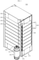
- FIG. 1 is a front perspective view schematically showing a battery pack according to an embodiment of the present disclosure.
- FIG. 2 is a rear perspective view schematically showing the battery pack according to an embodiment of the present disclosure.
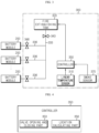
- FIG. 3 is a diagram schematically showing components of the battery pack according to an embodiment of the present disclosure.
- a battery pack 400 includes at least two battery modules 200 arranged in one direction, and a fire extinguishing unit 300 configured to extinguish a fire of the battery module 200.
- the fire extinguishing unit 300 may include a linear temperature sensor 310, a fire extinguishing tank 320, a pipe 330, and a valve 340.
- the pipe 330 may be configured to be connected to supply the fire extinguishing agent to each of the at least two battery modules 200.
- the pipe 330 may be made of a material that is not corroded by water.
- the pipe 330 may be made of stainless steel.
- One end of the pipe 330 may be connected to an outlet hole 321 of the fire extinguishing tank 320.
- the other end of the pipe 330 may have a shape extending to the inside of each of the at least two battery modules 200.
- the pipe 330 may include a common pipe 333 connected to the outlet hole 321 of the fire extinguishing tank 320 through which the fire extinguishing agent is discharged, a distribution pipe 336 having a distributed structure to be connected to an inlet hole 264 provided in each of the at least two battery modules 200 from the common pipe 333.
- the pipe 330 may include one common pipe 333 connected to the outlet hole 321 of the fire extinguishing tank 320, and eight distribution pipes 336 branched from the common pipe 333.
- the eight distribution pipes 336 may be configured to be connected to the inlet holes 264 of eight battery modules 200.
- the linear temperature sensor 310 may be configured to melt when a heat sensing material coated on two wires reaches a temperature higher over a reference temperature, to cause a short circuit between the two wires, thereby emitting a fire or overheat signal.
- the heat sensing material may be a thermoplastic resin that melts at 70 °C to 100 °C.
- the thermoplastic resin may be a polyester resin or an acrylic resin.
- the linear temperature sensor 310 may further include an insulating coating material configured to surround the heat sensing material.
- the coating material may include polyvinyl chloride.
- the linear temperature sensor 310 may have a structure extending linearly along at least two battery modules 200 arranged in one direction.
- the battery pack 400 may include eight battery modules 200 arranged in a vertical direction.
- the linear temperature sensor 310 may be configured so that one end thereof is connected to the controller 350 and extends downward along the eight battery modules 200 arranged in the vertical direction, and the other end thereof is connected to a resistor 315 at a distal end.
- a bracket (not shown) and a fixing buckle (not shown) may be used to partially fix the position of the linear temperature sensor 310.
- the battery pack 400 since the battery pack 400 includes the linear temperature sensor 310 linearly extending along at least two battery modules 200, it is possible to reduce the manufacturing cost of the battery pack.
- the battery pack 400 of the present disclosure uses only one linear temperature sensor 310 to detect the temperature of the plurality of battery modules 200, so a separate signal wire is not required and easy installation is secured due to a light and flexible design. Thus, the manufacturing cost of battery pack 400 may be greatly reduced.
- the location calculating part 356 may estimate the battery module 200 at which thermal runaway occurs by calculating the distance between the detected part of the linear temperature sensor 310 and the fire extinguishing unit 300.
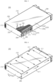
- FIG. 5 is a rear perspective view schematically showing a partial internal structure of a battery module, employed at the battery pack according to an embodiment of the present disclosure.
- the battery module 200 according to the present disclosure is not limited to the pouch-type secondary battery 110 described above, and various kinds of secondary batteries known at the time of filing of this application may be employed.
- the module housing 210 may have an inner space to accommodate the cell assembly 100 therein.
- the module housing 210 may include an upper cover 220, a base plate 240, a front cover 260, and a rear cover 250.
- the base plate 240 may have an area larger than the size of a bottom surface of the at least two cell assemblies 100 so as to mount the at least two cell assemblies 100 to an upper portion thereof.
- the base plate 240 may have a plate shape extending in a horizontal direction.
- the horizontal direction may refer to a direction parallel to the ground when the battery module 200 is placed on the ground, and may also refer to at least one direction on a plane perpendicular to the upper and lower direction.
- the rear cover 250 may be configured to cover the rear side of the cell assembly 100.
- the rear cover 250 may have a plate shape larger than the size of the rear surface of the plurality of secondary batteries 110.
- the module housing 210 may have a gas passage 211 through which the gas generated from the cell assembly 100 flows.
- the gas passage 211 may be a space elongated in the front and rear direction to communicate with the outside.
- the gas passage 211 may be provided at one of the left and right sides or both left and right sides of the cell assembly 100.
- the gas passage 211 may be a space between the upper or lower portion of the cell assembly 100 and the module housing 210. That is, the gas generated from the cell assembly 100 accommodated in the battery module 200 may move to both left and right sides of the cell assembly 100 through the gas passage 211 located at the upper or lower portion of the cell assembly 100 and be discharged out through a plurality of gas discharge holes 212 formed at the end of the gas passage 211 and perforated to communicate with the outside of the battery module 200.
- the inlet hole 264 may be provided at the right side of the rear cover 250.
- the fire extinguishing agent introduced through the inlet hole 264 may move along the gas passage 211 located at the left side of the cell assembly 100, and subsequently, the fire extinguishing agent may move to the gas passage 211 located at the right side of the cell assembly 100 through the gas passage 211 located at the upper or lower portion of the cell assembly 100. Through this process, it is possible to extinguish and cool the ignited or overheated cell assembly 100 inside the battery module 200.
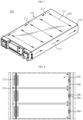
- FIG. 8 is a partial rear view schematically showing a portion of the battery pack according to an embodiment of the present disclosure.
- the linear temperature sensor 310 may be positioned so that a part of the linear temperature sensor 310 faces the gas discharge hole 212 provided to each of the at least two battery modules 200.
- the gas discharge hole 212 may be provided to the rear cover 250 of each of the two or more battery modules 200 stacked in the vertical direction.
- the linear temperature sensor 310 may be disposed at the outer side of each of the two or more battery modules 200 to face the gas discharge hole 212.
- the linear temperature sensor 310 may sense the hot air or gas with fast response. Accordingly, it is possible to increase the stability by rapidly responding to the thermal runaway of the battery pack 400 according to the present disclosure.
- FIG. 9 is a partial perspective view schematically showing a portion of the battery pack according to an embodiment of the present disclosure.
- the valve 340 may include a common valve 343 located at a part of the common pipe 333 to open or close the common pipe 333, and a distribution valve 346 located at a part of the distribution pipe 336 to open or close the distribution pipe 336.
- the common valve 343 may be an active valve capable of controlling the opening and closing of the valve 340 by receiving a signal from the valve opening and closing part of the fire extinguishing unit 300. For example, when at least one of the at least two battery modules 200 is heated over the predetermined temperature, the temperature is detected by the location calculating part 356 of the fire extinguishing unit 300, and the valve opening and closing part 353 may transmit an open signal to the common valve 343 to open the common valve 343 so that the extinguishing agent may be discharged from the fire extinguishing tank 320.
- the active valve may be a control valve, a motor-operated valve, a solenoid valve, or a pneumatic valve.
- FIG. 10 is a sectional view schematically showing of an internal configuration of a portion of the battery pack according to an embodiment of the present disclosure.
- the distribution valve 346 may be a passive valve 347 configured to be opened so that the fire extinguishing agent may be injected into the battery module 200 over the predetermined temperature.
- the passive valve 347 may be configured to open the valve 340 when the internal temperature of the battery module 200 is over the predetermined temperature.
- the passive valve 347 may include a glass bulb 347a and a predetermined fluid (not shown) accommodated in the glass bulb 347a. The glass bulb 347a may be configured to seal a passage 347c of the passive valve 347 through which the fluid flows.
- FIG. 11 is a partial perspective view schematically showing a pipe and a valve, employed at the battery pack according to an embodiment of the present disclosure.
- the passive valve 347 may be configured to be at least partially inserted into the inlet hole 264 configured to communicate with the gas passage 211 provided to the battery module 200.
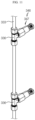
- the pipe 330 may include a plurality of distribution pipes 336 along the common pipe 333, and the distribution pipe 336 may be a Tee pipe or an elbow pipe.
- the distribution valve 346 may have provided at the distal end of the distribution pipe 336.
- the distribution valve 346 may be the passive valve 347.
- the passive valve 347 may include a glass bulb and a sprinkler head.
- at least a part of the distribution valve 346 may be inserted into the inlet hole 264 configured to communicate with the gas passage 211 provided to the battery module 200.
- the passive valve 347 since at least a part of the passive valve 347 is inserted into the inlet hole 264 perforated to communicate with the gas discharge passage provided to the battery module 200, when thermal runaway occurs, the passive valve 347 opens so that the fire extinguishing agent may be injected individually only to the million battery module at which the thermal runaway occurs. Moreover, since the fire extinguishing agent may be injected directly into the battery module 200, rather than to an outside thereof, it is possible to effectively extinguish and cool the fire of the battery module 200 at which thermal runaway occurs.
- FIG. 12 is a rear perspective view schematically showing a battery module, employed at a battery pack according to another embodiment of the present disclosure.
- FIG. 13 is a partial perspective view schematically showing a pipe and a valve, employed at the battery pack according to another embodiment of the present disclosure.
- a battery module 200A of another embodiment may have two or more inlet holes 264.
- a distribution pipe 336A may be connected to each of the two or more inlet holes 264.
- Any one of the two distribution pipes 336A may include the passive valve 347 that is opened when the battery module 200A is heated over the predetermined temperature.
- the passive valve 347 may be configured to be opened so that the fire extinguishing agent may be injected into the battery module 200A over the predetermined temperature.
- the passive valve 347 may be configured to be opened when the internal temperature of the battery module 200A increases over the predetermined temperature.
- the passive valve 347 may be located at the distal end of the distribution pipe 336A so that at least a part of the passive valve 347 may be inserted into the inlet hole 264.
- a pipe 330A of the battery pack includes a common pipe 333A and at least two or more distribution pipes 336A connected to the common pipe 333A.
- one of the two distribution pipes 336A may be connected to the passive valve 347, and the other of the two distribution pipes 336A may be connected to the active valve 348 that is opened when the battery module 200A is heated over the predetermined temperature.
- the active valve 348 may be configured to be opened when the linear temperature sensor 310 senses a battery module 200A over the predetermined temperature.
- the active valve 348 may be configured to operate by receiving an opening and closing signal from the valve opening and closing part 353 ( FIG. 4 ) of the controller 350 of the fire extinguishing unit 300.
- the active valve 348 may be, for example, a motor valve or a solenoid valve.
- one of the two distribution pipes 336A includes the passive valve 347 opened when the battery module 200A is heated over the predetermined temperature and the other of the two distribution pipes 336A includes the active valve 348, even if the passive valve 347 is not opened when thermal runaway occurs at the battery module 200A, the fire extinguishing unit 300 may transmit a signal to the active valve 348 to be opened, thereby increasing the safety of the battery pack 400.
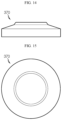
- FIGS. 14 and 15 are a front view and a plan view schematically showing a smoke sensor, employed at the battery pack according to an embodiment of the present disclosure.
- the fire extinguishing unit 300 may further include a smoke sensor 370 configured to sense a smoke discharged from the at least two battery modules 200.
- the smoke sensor 370 may be located at an uppermost portion T ( FIG. 1 ) of the at least two battery modules 200 stacked in the vertical direction. That is, if a fire occurs in the battery module 200, the generated gas may be moved upward, so it is preferable that the smoke sensor 370 is located at the uppermost portion T ( FIG. 1 ) of the at least two battery modules 200.
- the smoke sensor 370 may be configured to transmit a signal to the controller 350 of the fire extinguishing unit 300 when detecting smoke.
- the controller 350 may allow the valve opening and closing part 353 to open the common valve 343 and/or the distribution valve 346 according to the received signal.
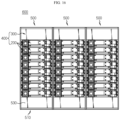
- FIG. 16 is a front view schematically showing an energy storage system according to an embodiment of the present disclosure.
- the rack case 510 is configured to have at least one side openable, and the battery module 200 may be inserted into the inner space through the open side.
- the rack case 510 may also be configured to allow such an open side to be closed.
- the battery rack 500 may further include a battery management system 530 (BMS) or the like.
- BMS battery management system 530
- an energy storage system 600 may include two or more battery racks 500.
- the two or more battery racks 500 may be arranged in one direction.
- the energy storage system 600 may be configured such that three battery racks 500 are arranged in one direction.
- the energy storage system 600 may have a central controller (not shown) capable of controlling charging and discharging of three battery racks 500.
- battery module 100 cell assembly 110: secondary battery 210: module housing 211: gas passage 212: gas discharge hole 264: inlet hole 300: fire extinguishing unit 310: linear temperature sensor 320: fire extinguishing tank 321: outlet hole 330, 333, 336: pipe, common pipe, distribution pipe 340, 343, 346: valve, common valve, distribution valve 350, 353, 356: controller, valve opening and closing part, location calculating part 370: smoke sensor 400: battery pack 500: battery rack 510: rack case 600: energy storage system
- the present disclosure relates to a battery pack.
- the present disclosure is available for industries associated with a battery rack including the battery pack, and a large-scale energy storage system including a plurality of battery racks.
Landscapes
- Chemical & Material Sciences (AREA)
- Chemical Kinetics & Catalysis (AREA)
- Electrochemistry (AREA)
- General Chemical & Material Sciences (AREA)
- Manufacturing & Machinery (AREA)
- Engineering & Computer Science (AREA)
- Public Health (AREA)
- Business, Economics & Management (AREA)
- Emergency Management (AREA)
- Health & Medical Sciences (AREA)
- Battery Mounting, Suspending (AREA)
- Gas Exhaust Devices For Batteries (AREA)
- Secondary Cells (AREA)
Claims (10)
- Batteriepack (400), umfassend:wenigstens zwei Batteriemodule (200), welche in einer Richtung angeordnet sind; undeine Feuerlöscheinheit (300), welche einen linearen Temperatursensor (310), welcher sich teilweise entlang der wenigstens zwei Batteriemodule (200) erstreckt und dazu eingerichtet ist, zu erfassen, ob wenigstens eines der wenigstens zwei Batteriemodule (200) eine Temperatur über einer vorbestimmten Temperatur aufweist, einen Feuerlöschtank (320), welcher dazu eingerichtet ist, ein Feuerlöschmittel darin aufzunehmen, eine Leitung (330), welche mit dem Feuerlöschtank (320) verbunden ist, um das Feuerlöschmittel aus dem Feuerlöschtank (320) jedem der wenigstens zwei Batteriemodule (200) zuzuführen, und ein Ventil (340) aufweist, welches geöffnet ist, um das Feuerlöschmittel von dem Feuerlöschtank (320) dem Batteriemodul (200) über der vorbestimmten Temperatur zuzuführen;wobei jedes der wenigstens zwei Batteriemodule (200) einen Gasdurchgang (211), welcher dazu eingerichtet ist, ein darin erzeugtes Gas an das Äußere abzugeben, und eine Mehrzahl von Gasabgabelöchern (212) aufweist, welche an einem Ende des Gasdurchgangs (211) gebildet sind und perforiert sind, um mit dem Äußeren in Verbindung zu stehen, undein Teil des linearen Temperatursensors (310) derart an einer äußeren Seite der zwei oder mehr Batteriemodule (200) angeordnet ist, dass er den Gasabgabelöchern (212) zugewandt ist, welche jeweils an den wenigstens zwei Batteriemodulen (200) bereitgestellt sind.
- Batteriepack (400) nach Anspruch 1,wobei die Leitung (330) eine gemeinsame Leitung (330), welche mit einem Auslassloch (321) des Feuerlöschtanks (320) verbunden ist, durch welches das Feuerlöschmittel ausgegeben wird, und eine Verteilungsleitung (336) umfasst, welche eine verteilte Struktur aufweist, welche von der gemeinsamen Leitung (333) zu einem Einlassloch (264) jedes der wenigstens zwei Batteriemodule (200) zu verbinden ist, durch welches das Feuerlöschmittel eingegeben wird, unddas Ventil (340) ein gemeinsames Ventil (343), welches in einem Teil der gemeinsamen Leitung (333) positioniert ist, um die gemeinsame Leitung (333) zu öffnen oder zu schließen, und ein Verteilungsventil (346) umfasst, welches in einem Teil der Verteilungsleitung (336) positioniert ist, um die Verteilungsleitung (336) zu öffnen oder zu schließen.
- Batteriepack (400) nach Anspruch 2,
wobei das Verteilungsventil (346) ein passives Ventil (347) ist, welches dazu eingerichtet ist, derart geöffnet zu sein, dass das Feuerlöschmittel in das Batteriemodul (200) über der vorbestimmten Temperatur injiziert wird. - Batteriepack (400) nach Anspruch 3,
wobei wenigstens ein Teil des passiven Ventils (347) in das Einlassloch (264) eingesetzt ist, welches derart gebildet ist, dass es mit dem Gasdurchgang (211) in Verbindung steht, welcher an dem Batteriemodul (200) bereitgestellt ist. - Batteriepack (400) nach Anspruch 2,
wobei das gemeinsame Ventil (343) ein aktives Ventil ist, welches dazu eingerichtet ist, geöffnet zu sein, wenn der lineare Temperatursensor (310) das Batteriemodul (200) über der vorbestimmten Temperatur erfasst. - Batteriepack (400) nach Anspruch 2,
wobei die Feuerlöscheinheit (300) ferner einen Positionsberechnungsteil (356) umfasst, welcher dazu eingerichtet ist, ein Signal von dem linearen Temperatursensor (310) zu empfangen und eine Position des Batteriemoduls (200) über der vorbestimmten Temperatur zu berechnen. - Batteriepack (400) nach Anspruch 2,wobei das Batteriemodul (200) zwei oder mehr Einlasslöcher (264) aufweist,die Verteilungsleitung (336) mit jedem der zwei oder mehr Einlasslöcher (264) verbunden ist,jegliche der zwei Verteilungsleitungen (336) ein passives Ventil (347) umfasst, welches dazu eingerichtet ist, geöffnet zu sein, wenn das Batteriemodul (200) über die vorbestimmte Temperatur erwärmt ist, unddie andere der zwei Verteilungsleitungen (336) ein aktives Ventil (348) umfasst, welches dazu eingerichtet ist, geöffnet zu sein, wenn das Batteriemodul (200) über die vorbestimmte Temperatur erwärmt ist.
- Batteriepack (400) nach Anspruch 1,
wobei die Feuerlöscheinheit (300) ferner einen Rauchsensor (370) umfasst, welcher dazu eingerichtet ist, einen von den wenigstens zwei Batteriemodulen (200) abgegebenen Rauch zu erfassen. - Batteriegestell (500), umfassend:einen Batteriepack (400) nach einem der Ansprüche 1 bis 8; undein Gestellgehäuse (510), welches dazu eingerichtet ist, den Batteriepack (400) aufzunehmen.
- Energiespeichersystem (600), umfassend zwei oder mehr Batteriegestelle (500) nach Anspruch 9.
Applications Claiming Priority (2)
| Application Number | Priority Date | Filing Date | Title |
|---|---|---|---|
| KR1020190096939A KR102866645B1 (ko) | 2019-08-08 | 2019-08-08 | 소화 유닛을 포함한 배터리 팩 |
| PCT/KR2020/010509 WO2021025539A1 (ko) | 2019-08-08 | 2020-08-07 | 소화 유닛을 포함한 배터리 팩 |
Publications (3)
| Publication Number | Publication Date |
|---|---|
| EP4002543A1 EP4002543A1 (de) | 2022-05-25 |
| EP4002543A4 EP4002543A4 (de) | 2022-12-21 |
| EP4002543B1 true EP4002543B1 (de) | 2025-06-25 |
Family
ID=74503575
Family Applications (1)
| Application Number | Title | Priority Date | Filing Date |
|---|---|---|---|
| EP20850852.3A Active EP4002543B1 (de) | 2019-08-08 | 2020-08-07 | Batteriepack mit löscheinheit |
Country Status (9)
| Country | Link |
|---|---|
| US (2) | US12034177B2 (de) |
| EP (1) | EP4002543B1 (de) |
| JP (1) | JP7233597B2 (de) |
| KR (2) | KR102866645B1 (de) |
| CN (1) | CN114175358B (de) |
| AU (1) | AU2020324313B2 (de) |
| ES (1) | ES3036892T3 (de) |
| HU (1) | HUE072279T2 (de) |
| WO (1) | WO2021025539A1 (de) |
Families Citing this family (22)
| Publication number | Priority date | Publication date | Assignee | Title |
|---|---|---|---|---|
| KR102775048B1 (ko) | 2019-09-05 | 2025-02-27 | 주식회사 엘지에너지솔루션 | 소화 유닛을 포함한 배터리 팩 |
| KR102775084B1 (ko) | 2019-09-19 | 2025-02-27 | 주식회사 엘지에너지솔루션 | 소화 유닛을 포함한 배터리 팩 |
| KR102718427B1 (ko) * | 2021-02-02 | 2024-10-16 | 주식회사 엘지에너지솔루션 | 셀 단위 가스계 소화약제 가이드 날개를 적용한 배터리 모듈 및 이를 포함하는 배터리 랙과 에너지 저장장치 |
| EP4050719A1 (de) * | 2021-02-26 | 2022-08-31 | Polarium Energy Solutions AB | Batterievorrichtung mit schutz gegen feuerausbreitung |
| JP7829570B2 (ja) * | 2021-03-19 | 2026-03-13 | ザ ケマーズ カンパニー エフシー リミテッド ライアビリティ カンパニー | リチウムイオン電池の熱保護 |
| KR20220152918A (ko) * | 2021-05-10 | 2022-11-17 | 삼성에스디아이 주식회사 | 에너지 저장 시스템의 소화 시스템 |
| KR102442567B1 (ko) | 2021-08-23 | 2022-09-14 | 인셀(주) | 이차 전지 시스템 |
| CN116470226A (zh) * | 2022-01-18 | 2023-07-21 | 开利公司 | 安全气体的抑制 |
| KR102782537B1 (ko) * | 2022-01-27 | 2025-03-18 | 삼성에스디아이 주식회사 | 에너지 저장 시스템 |
| KR102407796B1 (ko) * | 2022-01-28 | 2022-06-10 | 정대원 | 배터리 에너지저장시스템의 소화장치 |
| KR102736403B1 (ko) * | 2022-03-17 | 2024-11-29 | 주식회사카이저솔루션 | 배터리팩의 화재 대응 시스템 |
| KR102531012B1 (ko) | 2022-03-17 | 2023-05-11 | 김동휘 | 소화약제 배관을 포함하는 전기 모빌리티 충전용 케이블 및 이와 결합된 인렛, 커넥터 및 배터리팩 |
| KR102531013B1 (ko) | 2022-03-17 | 2023-05-12 | 김동휘 | 전기 모빌리티 배터리팩의 화재감지 및 소화방법 |
| CN115566299B (zh) * | 2022-09-30 | 2025-05-27 | 中广核风电有限公司 | 一种分布式储能系统及其控制方法 |
| KR102728774B1 (ko) * | 2022-11-14 | 2024-11-11 | 주식회사 아산에스앤테크 | 배터리 모듈용 소화시스템 및 소화방법 |
| US20240162560A1 (en) * | 2022-11-15 | 2024-05-16 | Enphase Energy, Inc. | Storage system configured for use with an energy management system |
| TWI849755B (zh) * | 2023-02-17 | 2024-07-21 | 順達科技股份有限公司 | 具有抑制電池延燒之電池模組及其抑制電池延燒之控制方法 |
| KR20240138637A (ko) | 2023-03-09 | 2024-09-20 | 김종삼 | 리튬이온배터리 모듈단위의 열 폭주에 대한 화재진압장치 및 방법 |
| US20250018335A1 (en) * | 2023-07-13 | 2025-01-16 | Fca Us Llc | Electric vehicle exhaust system |
| KR20250015051A (ko) * | 2023-07-24 | 2025-02-03 | 삼성에스디아이 주식회사 | 배터리 팩 |
| KR102939870B1 (ko) * | 2023-10-16 | 2026-03-17 | 주식회사 티엔피솔루션 | 불량을 최소화시킬 수 있는 배터리 모듈 제조장치 및 이에 의해 제조된 배터리의 관리 시스템 |
| KR102702811B1 (ko) * | 2024-04-17 | 2024-09-04 | 주식회사 에이치티씨 | 소화기능을 갖는 전기자동차용 배터리 팩 |
Family Cites Families (32)
| Publication number | Priority date | Publication date | Assignee | Title |
|---|---|---|---|---|
| DE4419281C1 (de) | 1994-06-01 | 1995-12-14 | Daimler Benz Ag | Hochtemperaturbatterie |
| JP3983139B2 (ja) | 2002-08-30 | 2007-09-26 | 三洋電機株式会社 | 車両用の電源装置 |
| JP4565950B2 (ja) | 2004-09-30 | 2010-10-20 | 三洋電機株式会社 | 電源装置 |
| KR101069752B1 (ko) | 2005-03-16 | 2011-10-04 | 삼성전자주식회사 | 안테나 성능 개선을 위한 슬라이드 타입 휴대용 단말기의가요성 인쇄회로 연결 구조 |
| KR100778435B1 (ko) | 2005-07-05 | 2007-11-21 | 삼성에스디아이 주식회사 | 전지 모듈 소화 시스템 |
| JP5074809B2 (ja) | 2007-04-16 | 2012-11-14 | ホーチキ株式会社 | 閉鎖型消火ヘッド |
| JP4953013B2 (ja) * | 2007-08-23 | 2012-06-13 | トヨタ自動車株式会社 | 異常監視装置及び該装置を備えた二次電池収容棚 |
| KR100938591B1 (ko) * | 2007-11-20 | 2010-01-26 | 지멘스 주식회사 | 광센서감지기를 이용한 화재감지시스템 |
| JP2009218078A (ja) * | 2008-03-10 | 2009-09-24 | Nissan Motor Co Ltd | 非水電解質二次電池 |
| JP5331517B2 (ja) | 2008-04-14 | 2013-10-30 | 日産自動車株式会社 | 組電池、および組電池を搭載した車両 |
| JP4786700B2 (ja) * | 2008-12-24 | 2011-10-05 | 三菱重工業株式会社 | 電池モジュール |
| JP5421632B2 (ja) | 2009-03-27 | 2014-02-19 | 伊藤忠商事株式会社 | 電池パック |
| KR101057556B1 (ko) * | 2010-02-03 | 2011-08-17 | 에스비리모티브 주식회사 | 배터리 시스템 및 그 구동 방법 |
| US8851197B2 (en) * | 2011-04-28 | 2014-10-07 | Pacific Scientific Energetic Materials Company | Self contained fire extinguisher system including a linear temperature sensor |
| WO2013036087A2 (ko) | 2011-09-08 | 2013-03-14 | 주식회사 엘지화학 | 배터리 팩 화재진압 장치 |
| JP6126816B2 (ja) | 2012-09-24 | 2017-05-10 | 日本碍子株式会社 | 組み合わせ製品 |
| JP6103887B2 (ja) | 2012-11-01 | 2017-03-29 | ホーチキ株式会社 | 電力貯蔵システム |
| KR101340365B1 (ko) | 2012-11-22 | 2013-12-11 | 자동차부품연구원 | 배터리 온도 조절 장치 |
| JP6189603B2 (ja) | 2013-02-19 | 2017-08-30 | ホーチキ株式会社 | 消火装置 |
| KR101652975B1 (ko) | 2014-08-28 | 2016-09-12 | (주)오렌지파워 | 에너지저장시스템 |
| JP2016067642A (ja) | 2014-09-30 | 2016-05-09 | 三菱重工業株式会社 | 蓄電装置消火設備、蓄電装置および蓄電装置消火方法 |
| KR101829093B1 (ko) | 2014-10-22 | 2018-03-29 | 주식회사 엘지화학 | 배터리 시스템의 냉각 공기 흐름 제어 시스템 및 방법 |
| CN204158920U (zh) * | 2014-10-24 | 2015-02-18 | 江西凯马百路佳客车有限公司 | 一种分体式电池箱自动灭火装置 |
| CN104667459A (zh) * | 2015-03-17 | 2015-06-03 | 国家电网公司 | 分区域保护式变电站消防监测预警及消防系统 |
| JP2019075191A (ja) | 2016-03-08 | 2019-05-16 | パナソニックIpマネジメント株式会社 | 蓄電装置 |
| CN110100044B (zh) | 2016-12-22 | 2022-03-04 | 汉高股份有限及两合公司 | 儿茶酚化合物和官能化共反应化合物的预形成的反应产物减少裸金属表面氧化的用途 |
| KR102401539B1 (ko) | 2017-12-14 | 2022-05-23 | 주식회사 엘지에너지솔루션 | 셀 밸런싱 장치 및 방법 |
| KR101939812B1 (ko) | 2018-08-29 | 2019-01-18 | (주)대은 | 안전성이 강화된 공조 기능을 포함하는 ess시스템 |
| KR101918022B1 (ko) * | 2018-08-29 | 2018-11-13 | (주)대은 | 공조 및 소화 기능을 포함하는 ess시스템 |
| CN109513135B (zh) * | 2018-12-07 | 2023-09-08 | 国网浙江省电力有限公司电力科学研究院 | 储能集装箱消防系统及方法 |
| CN210583417U (zh) * | 2019-08-30 | 2020-05-22 | 阳光电源股份有限公司 | 一种户外储能系统机柜以及户外储能系统 |
| KR102935720B1 (ko) * | 2020-01-30 | 2026-03-05 | 주식회사 엘지에너지솔루션 | 소화 유닛을 포함한 배터리 팩, 이를 포함하는 배터리 랙, 및 전력 저장 시스템 |
-
2019
- 2019-08-08 KR KR1020190096939A patent/KR102866645B1/ko active Active
-
2020
- 2020-08-07 HU HUE20850852A patent/HUE072279T2/hu unknown
- 2020-08-07 JP JP2022500981A patent/JP7233597B2/ja active Active
- 2020-08-07 US US17/628,055 patent/US12034177B2/en active Active
- 2020-08-07 EP EP20850852.3A patent/EP4002543B1/de active Active
- 2020-08-07 WO PCT/KR2020/010509 patent/WO2021025539A1/ko not_active Ceased
- 2020-08-07 ES ES20850852T patent/ES3036892T3/es active Active
- 2020-08-07 AU AU2020324313A patent/AU2020324313B2/en active Active
- 2020-08-07 CN CN202080055076.8A patent/CN114175358B/zh active Active
-
2024
- 2024-06-11 US US18/739,734 patent/US12407064B2/en active Active
-
2025
- 2025-09-24 KR KR1020250138239A patent/KR20250152515A/ko active Pending
Also Published As
| Publication number | Publication date |
|---|---|
| KR20250152515A (ko) | 2025-10-23 |
| JP2022540463A (ja) | 2022-09-15 |
| EP4002543A1 (de) | 2022-05-25 |
| CN114175358B (zh) | 2024-12-31 |
| WO2021025539A1 (ko) | 2021-02-11 |
| US12407064B2 (en) | 2025-09-02 |
| ES3036892T3 (en) | 2025-09-25 |
| JP7233597B2 (ja) | 2023-03-06 |
| AU2020324313B2 (en) | 2026-04-23 |
| US20240332729A1 (en) | 2024-10-03 |
| CN114175358A (zh) | 2022-03-11 |
| HUE072279T2 (hu) | 2025-11-28 |
| US20220278417A1 (en) | 2022-09-01 |
| KR102866645B1 (ko) | 2025-09-29 |
| EP4002543A4 (de) | 2022-12-21 |
| US12034177B2 (en) | 2024-07-09 |
| AU2020324313A1 (en) | 2022-03-17 |
| KR20210017535A (ko) | 2021-02-17 |
Similar Documents
| Publication | Publication Date | Title |
|---|---|---|
| EP4002543B1 (de) | Batteriepack mit löscheinheit | |
| US12283713B2 (en) | Battery pack comprising fire extinguishing unit | |
| US12357859B2 (en) | Battery pack comprising fire extinguishing unit, battery rack comprising same, and power storage system | |
| EP4009414B1 (de) | Batteriepack mit löscheinheit | |
| KR20210054330A (ko) | 배터리 팩 |
Legal Events
| Date | Code | Title | Description |
|---|---|---|---|
| STAA | Information on the status of an ep patent application or granted ep patent |
Free format text: STATUS: THE INTERNATIONAL PUBLICATION HAS BEEN MADE |
|
| PUAI | Public reference made under article 153(3) epc to a published international application that has entered the european phase |
Free format text: ORIGINAL CODE: 0009012 |
|
| STAA | Information on the status of an ep patent application or granted ep patent |
Free format text: STATUS: REQUEST FOR EXAMINATION WAS MADE |
|
| 17P | Request for examination filed |
Effective date: 20220218 |
|
| AK | Designated contracting states |
Kind code of ref document: A1 Designated state(s): AL AT BE BG CH CY CZ DE DK EE ES FI FR GB GR HR HU IE IS IT LI LT LU LV MC MK MT NL NO PL PT RO RS SE SI SK SM TR |
|
| DAV | Request for validation of the european patent (deleted) | ||
| DAX | Request for extension of the european patent (deleted) | ||
| A4 | Supplementary search report drawn up and despatched |
Effective date: 20221121 |
|
| RIC1 | Information provided on ipc code assigned before grant |
Ipc: H01M 50/383 20210101ALI20221115BHEP Ipc: H01M 50/367 20210101ALI20221115BHEP Ipc: H01M 50/209 20210101ALI20221115BHEP Ipc: A62C 3/16 20060101ALI20221115BHEP Ipc: H01M 10/627 20140101ALI20221115BHEP Ipc: H01M 10/48 20060101ALI20221115BHEP Ipc: H01M 10/42 20060101AFI20221115BHEP |
|
| GRAP | Despatch of communication of intention to grant a patent |
Free format text: ORIGINAL CODE: EPIDOSNIGR1 |
|
| STAA | Information on the status of an ep patent application or granted ep patent |
Free format text: STATUS: GRANT OF PATENT IS INTENDED |
|
| INTG | Intention to grant announced |
Effective date: 20250402 |
|
| GRAS | Grant fee paid |
Free format text: ORIGINAL CODE: EPIDOSNIGR3 |
|
| GRAA | (expected) grant |
Free format text: ORIGINAL CODE: 0009210 |
|
| STAA | Information on the status of an ep patent application or granted ep patent |
Free format text: STATUS: THE PATENT HAS BEEN GRANTED |
|
| P01 | Opt-out of the competence of the unified patent court (upc) registered |
Free format text: CASE NUMBER: APP_21316/2025 Effective date: 20250506 |
|
| AK | Designated contracting states |
Kind code of ref document: B1 Designated state(s): AL AT BE BG CH CY CZ DE DK EE ES FI FR GB GR HR HU IE IS IT LI LT LU LV MC MK MT NL NO PL PT RO RS SE SI SK SM TR |
|
| REG | Reference to a national code |
Ref country code: GB Ref legal event code: FG4D |
|
| REG | Reference to a national code |
Ref country code: CH Ref legal event code: EP |
|
| REG | Reference to a national code |
Ref country code: DE Ref legal event code: R096 Ref document number: 602020053464 Country of ref document: DE |
|
| REG | Reference to a national code |
Ref country code: CH Ref legal event code: EP |
|
| REG | Reference to a national code |
Ref country code: IE Ref legal event code: FG4D |
|
| REG | Reference to a national code |
Ref country code: ES Ref legal event code: FG2A Ref document number: 3036892 Country of ref document: ES Kind code of ref document: T3 Effective date: 20250925 |
|
| PG25 | Lapsed in a contracting state [announced via postgrant information from national office to epo] |
Ref country code: FI Free format text: LAPSE BECAUSE OF FAILURE TO SUBMIT A TRANSLATION OF THE DESCRIPTION OR TO PAY THE FEE WITHIN THE PRESCRIBED TIME-LIMIT Effective date: 20250625 |
|
| PGFP | Annual fee paid to national office [announced via postgrant information from national office to epo] |
Ref country code: ES Payment date: 20250911 Year of fee payment: 6 |
|
| PGFP | Annual fee paid to national office [announced via postgrant information from national office to epo] |
Ref country code: DE Payment date: 20250721 Year of fee payment: 6 |
|
| REG | Reference to a national code |
Ref country code: LT Ref legal event code: MG9D |
|
| PG25 | Lapsed in a contracting state [announced via postgrant information from national office to epo] |
Ref country code: GR Free format text: LAPSE BECAUSE OF FAILURE TO SUBMIT A TRANSLATION OF THE DESCRIPTION OR TO PAY THE FEE WITHIN THE PRESCRIBED TIME-LIMIT Effective date: 20250926 Ref country code: NO Free format text: LAPSE BECAUSE OF FAILURE TO SUBMIT A TRANSLATION OF THE DESCRIPTION OR TO PAY THE FEE WITHIN THE PRESCRIBED TIME-LIMIT Effective date: 20250925 |
|
| PG25 | Lapsed in a contracting state [announced via postgrant information from national office to epo] |
Ref country code: BG Free format text: LAPSE BECAUSE OF FAILURE TO SUBMIT A TRANSLATION OF THE DESCRIPTION OR TO PAY THE FEE WITHIN THE PRESCRIBED TIME-LIMIT Effective date: 20250625 |
|
| PGFP | Annual fee paid to national office [announced via postgrant information from national office to epo] |
Ref country code: HU Payment date: 20250929 Year of fee payment: 6 Ref country code: BE Payment date: 20250722 Year of fee payment: 6 Ref country code: GB Payment date: 20250722 Year of fee payment: 6 |
|
| PG25 | Lapsed in a contracting state [announced via postgrant information from national office to epo] |
Ref country code: HR Free format text: LAPSE BECAUSE OF FAILURE TO SUBMIT A TRANSLATION OF THE DESCRIPTION OR TO PAY THE FEE WITHIN THE PRESCRIBED TIME-LIMIT Effective date: 20250625 |
|
| PGFP | Annual fee paid to national office [announced via postgrant information from national office to epo] |
Ref country code: FR Payment date: 20250725 Year of fee payment: 6 |
|
| PG25 | Lapsed in a contracting state [announced via postgrant information from national office to epo] |
Ref country code: RS Free format text: LAPSE BECAUSE OF FAILURE TO SUBMIT A TRANSLATION OF THE DESCRIPTION OR TO PAY THE FEE WITHIN THE PRESCRIBED TIME-LIMIT Effective date: 20250925 |
|
| PG25 | Lapsed in a contracting state [announced via postgrant information from national office to epo] |
Ref country code: LV Free format text: LAPSE BECAUSE OF FAILURE TO SUBMIT A TRANSLATION OF THE DESCRIPTION OR TO PAY THE FEE WITHIN THE PRESCRIBED TIME-LIMIT Effective date: 20250625 |
|
| REG | Reference to a national code |
Ref country code: NL Ref legal event code: MP Effective date: 20250625 |
|
| PG25 | Lapsed in a contracting state [announced via postgrant information from national office to epo] |
Ref country code: NL Free format text: LAPSE BECAUSE OF FAILURE TO SUBMIT A TRANSLATION OF THE DESCRIPTION OR TO PAY THE FEE WITHIN THE PRESCRIBED TIME-LIMIT Effective date: 20250625 |
|
| REG | Reference to a national code |
Ref country code: HU Ref legal event code: AG4A Ref document number: E072279 Country of ref document: HU |
|
| PG25 | Lapsed in a contracting state [announced via postgrant information from national office to epo] |
Ref country code: PT Free format text: LAPSE BECAUSE OF FAILURE TO SUBMIT A TRANSLATION OF THE DESCRIPTION OR TO PAY THE FEE WITHIN THE PRESCRIBED TIME-LIMIT Effective date: 20251027 |
|
| REG | Reference to a national code |
Ref country code: AT Ref legal event code: MK05 Ref document number: 1807536 Country of ref document: AT Kind code of ref document: T Effective date: 20250625 |
|
| PG25 | Lapsed in a contracting state [announced via postgrant information from national office to epo] |
Ref country code: IS Free format text: LAPSE BECAUSE OF FAILURE TO SUBMIT A TRANSLATION OF THE DESCRIPTION OR TO PAY THE FEE WITHIN THE PRESCRIBED TIME-LIMIT Effective date: 20251025 |
|
| PG25 | Lapsed in a contracting state [announced via postgrant information from national office to epo] |
Ref country code: AT Free format text: LAPSE BECAUSE OF FAILURE TO SUBMIT A TRANSLATION OF THE DESCRIPTION OR TO PAY THE FEE WITHIN THE PRESCRIBED TIME-LIMIT Effective date: 20250625 Ref country code: SM Free format text: LAPSE BECAUSE OF FAILURE TO SUBMIT A TRANSLATION OF THE DESCRIPTION OR TO PAY THE FEE WITHIN THE PRESCRIBED TIME-LIMIT Effective date: 20250625 |
|
| PG25 | Lapsed in a contracting state [announced via postgrant information from national office to epo] |
Ref country code: CZ Free format text: LAPSE BECAUSE OF FAILURE TO SUBMIT A TRANSLATION OF THE DESCRIPTION OR TO PAY THE FEE WITHIN THE PRESCRIBED TIME-LIMIT Effective date: 20250625 |
|
| PG25 | Lapsed in a contracting state [announced via postgrant information from national office to epo] |
Ref country code: PL Free format text: LAPSE BECAUSE OF FAILURE TO SUBMIT A TRANSLATION OF THE DESCRIPTION OR TO PAY THE FEE WITHIN THE PRESCRIBED TIME-LIMIT Effective date: 20250625 |
|
| PG25 | Lapsed in a contracting state [announced via postgrant information from national office to epo] |
Ref country code: EE Free format text: LAPSE BECAUSE OF FAILURE TO SUBMIT A TRANSLATION OF THE DESCRIPTION OR TO PAY THE FEE WITHIN THE PRESCRIBED TIME-LIMIT Effective date: 20250625 |
|
| PG25 | Lapsed in a contracting state [announced via postgrant information from national office to epo] |
Ref country code: SK Free format text: LAPSE BECAUSE OF FAILURE TO SUBMIT A TRANSLATION OF THE DESCRIPTION OR TO PAY THE FEE WITHIN THE PRESCRIBED TIME-LIMIT Effective date: 20250625 |
|
| PG25 | Lapsed in a contracting state [announced via postgrant information from national office to epo] |
Ref country code: RO Free format text: LAPSE BECAUSE OF FAILURE TO SUBMIT A TRANSLATION OF THE DESCRIPTION OR TO PAY THE FEE WITHIN THE PRESCRIBED TIME-LIMIT Effective date: 20250625 |
|
| REG | Reference to a national code |
Ref country code: CH Ref legal event code: H13 Free format text: ST27 STATUS EVENT CODE: U-0-0-H10-H13 (AS PROVIDED BY THE NATIONAL OFFICE) Effective date: 20260324 |
|
| PG25 | Lapsed in a contracting state [announced via postgrant information from national office to epo] |
Ref country code: MC Free format text: LAPSE BECAUSE OF FAILURE TO SUBMIT A TRANSLATION OF THE DESCRIPTION OR TO PAY THE FEE WITHIN THE PRESCRIBED TIME-LIMIT Effective date: 20250625 |
|
| PG25 | Lapsed in a contracting state [announced via postgrant information from national office to epo] |
Ref country code: DK Free format text: LAPSE BECAUSE OF FAILURE TO SUBMIT A TRANSLATION OF THE DESCRIPTION OR TO PAY THE FEE WITHIN THE PRESCRIBED TIME-LIMIT Effective date: 20250625 |
|
| PG25 | Lapsed in a contracting state [announced via postgrant information from national office to epo] |
Ref country code: LU Free format text: LAPSE BECAUSE OF NON-PAYMENT OF DUE FEES Effective date: 20250807 Ref country code: IT Free format text: LAPSE BECAUSE OF FAILURE TO SUBMIT A TRANSLATION OF THE DESCRIPTION OR TO PAY THE FEE WITHIN THE PRESCRIBED TIME-LIMIT Effective date: 20250625 |
|
| PG25 | Lapsed in a contracting state [announced via postgrant information from national office to epo] |
Ref country code: CH Free format text: LAPSE BECAUSE OF NON-PAYMENT OF DUE FEES Effective date: 20250831 |
|
| PLBE | No opposition filed within time limit |
Free format text: ORIGINAL CODE: 0009261 |
|
| STAA | Information on the status of an ep patent application or granted ep patent |
Free format text: STATUS: NO OPPOSITION FILED WITHIN TIME LIMIT |