EP4002545A1 - Circuit de protection de charge/décharge, dispositif terminal, et procédé de commande de décharge de batterie - Google Patents
Circuit de protection de charge/décharge, dispositif terminal, et procédé de commande de décharge de batterie Download PDFInfo
- Publication number
- EP4002545A1 EP4002545A1 EP20845898.4A EP20845898A EP4002545A1 EP 4002545 A1 EP4002545 A1 EP 4002545A1 EP 20845898 A EP20845898 A EP 20845898A EP 4002545 A1 EP4002545 A1 EP 4002545A1
- Authority
- EP
- European Patent Office
- Prior art keywords
- battery
- voltage
- circuit
- discharging
- under
- Prior art date
- Legal status (The legal status is an assumption and is not a legal conclusion. Google has not performed a legal analysis and makes no representation as to the accuracy of the status listed.)
- Granted
Links
Images


Classifications
-
- G—PHYSICS
- G01—MEASURING; TESTING
- G01R—MEASURING ELECTRIC VARIABLES; MEASURING MAGNETIC VARIABLES
- G01R31/00—Arrangements for testing electric properties; Arrangements for locating electric faults; Arrangements for electrical testing characterised by what is being tested not provided for elsewhere
- G01R31/36—Arrangements for testing, measuring or monitoring the electrical condition of accumulators or electric batteries, e.g. capacity or state of charge [SoC]
- G01R31/374—Arrangements for testing, measuring or monitoring the electrical condition of accumulators or electric batteries, e.g. capacity or state of charge [SoC] with means for correcting the measurement for temperature or ageing
-
- G—PHYSICS
- G01—MEASURING; TESTING
- G01R—MEASURING ELECTRIC VARIABLES; MEASURING MAGNETIC VARIABLES
- G01R31/00—Arrangements for testing electric properties; Arrangements for locating electric faults; Arrangements for electrical testing characterised by what is being tested not provided for elsewhere
- G01R31/36—Arrangements for testing, measuring or monitoring the electrical condition of accumulators or electric batteries, e.g. capacity or state of charge [SoC]
- G01R31/382—Arrangements for monitoring battery or accumulator variables, e.g. SoC
- G01R31/3842—Arrangements for monitoring battery or accumulator variables, e.g. SoC combining voltage and current measurements
-
- H—ELECTRICITY
- H01—ELECTRIC ELEMENTS
- H01M—PROCESSES OR MEANS, e.g. BATTERIES, FOR THE DIRECT CONVERSION OF CHEMICAL ENERGY INTO ELECTRICAL ENERGY
- H01M10/00—Secondary cells; Manufacture thereof
- H01M10/42—Methods or arrangements for servicing or maintenance of secondary cells or secondary half-cells
- H01M10/44—Methods for charging or discharging
- H01M10/443—Methods for charging or discharging in response to temperature
-
- H—ELECTRICITY
- H02—GENERATION; CONVERSION OR DISTRIBUTION OF ELECTRIC POWER
- H02J—ELECTRIC POWER NETWORKS; CIRCUIT ARRANGEMENTS OR SYSTEMS FOR SUPPLYING OR DISTRIBUTING ELECTRIC POWER; SYSTEMS FOR STORING ELECTRIC ENERGY
- H02J7/00—Circuit arrangements for charging or discharging batteries or for supplying loads from batteries
- H02J7/60—Circuit arrangements for charging or discharging batteries or for supplying loads from batteries including safety or protection arrangements
- H02J7/63—Circuit arrangements for charging or discharging batteries or for supplying loads from batteries including safety or protection arrangements against overdischarge
-
- H—ELECTRICITY
- H02—GENERATION; CONVERSION OR DISTRIBUTION OF ELECTRIC POWER
- H02J—ELECTRIC POWER NETWORKS; CIRCUIT ARRANGEMENTS OR SYSTEMS FOR SUPPLYING OR DISTRIBUTING ELECTRIC POWER; SYSTEMS FOR STORING ELECTRIC ENERGY
- H02J7/00—Circuit arrangements for charging or discharging batteries or for supplying loads from batteries
- H02J7/90—Regulation of charging or discharging current or voltage
- H02J7/933—Regulation of charging or discharging current or voltage the cycle being controlled or terminated in response to electric parameters
-
- H—ELECTRICITY
- H01—ELECTRIC ELEMENTS
- H01M—PROCESSES OR MEANS, e.g. BATTERIES, FOR THE DIRECT CONVERSION OF CHEMICAL ENERGY INTO ELECTRICAL ENERGY
- H01M10/00—Secondary cells; Manufacture thereof
- H01M10/42—Methods or arrangements for servicing or maintenance of secondary cells or secondary half-cells
- H01M10/48—Accumulators combined with arrangements for measuring, testing or indicating the condition of cells, e.g. the level or density of the electrolyte
- H01M10/486—Accumulators combined with arrangements for measuring, testing or indicating the condition of cells, e.g. the level or density of the electrolyte for measuring temperature
-
- H—ELECTRICITY
- H01—ELECTRIC ELEMENTS
- H01M—PROCESSES OR MEANS, e.g. BATTERIES, FOR THE DIRECT CONVERSION OF CHEMICAL ENERGY INTO ELECTRICAL ENERGY
- H01M10/00—Secondary cells; Manufacture thereof
- H01M10/42—Methods or arrangements for servicing or maintenance of secondary cells or secondary half-cells
- H01M10/425—Structural combination with electronic components, e.g. electronic circuits integrated to the outside of the casing
- H01M2010/4271—Battery management systems including electronic circuits, e.g. control of current or voltage to keep battery in healthy state, cell balancing
-
- H—ELECTRICITY
- H01—ELECTRIC ELEMENTS
- H01M—PROCESSES OR MEANS, e.g. BATTERIES, FOR THE DIRECT CONVERSION OF CHEMICAL ENERGY INTO ELECTRICAL ENERGY
- H01M2200/00—Safety devices for primary or secondary batteries
- H01M2200/10—Temperature sensitive devices
-
- H—ELECTRICITY
- H02—GENERATION; CONVERSION OR DISTRIBUTION OF ELECTRIC POWER
- H02J—ELECTRIC POWER NETWORKS; CIRCUIT ARRANGEMENTS OR SYSTEMS FOR SUPPLYING OR DISTRIBUTING ELECTRIC POWER; SYSTEMS FOR STORING ELECTRIC ENERGY
- H02J7/00—Circuit arrangements for charging or discharging batteries or for supplying loads from batteries
- H02J7/60—Circuit arrangements for charging or discharging batteries or for supplying loads from batteries including safety or protection arrangements
- H02J7/62—Circuit arrangements for charging or discharging batteries or for supplying loads from batteries including safety or protection arrangements against overcurrent
-
- H—ELECTRICITY
- H02—GENERATION; CONVERSION OR DISTRIBUTION OF ELECTRIC POWER
- H02J—ELECTRIC POWER NETWORKS; CIRCUIT ARRANGEMENTS OR SYSTEMS FOR SUPPLYING OR DISTRIBUTING ELECTRIC POWER; SYSTEMS FOR STORING ELECTRIC ENERGY
- H02J7/00—Circuit arrangements for charging or discharging batteries or for supplying loads from batteries
- H02J7/60—Circuit arrangements for charging or discharging batteries or for supplying loads from batteries including safety or protection arrangements
- H02J7/65—Circuit arrangements for charging or discharging batteries or for supplying loads from batteries including safety or protection arrangements against overtemperature
-
- H—ELECTRICITY
- H02—GENERATION; CONVERSION OR DISTRIBUTION OF ELECTRIC POWER
- H02J—ELECTRIC POWER NETWORKS; CIRCUIT ARRANGEMENTS OR SYSTEMS FOR SUPPLYING OR DISTRIBUTING ELECTRIC POWER; SYSTEMS FOR STORING ELECTRIC ENERGY
- H02J7/00—Circuit arrangements for charging or discharging batteries or for supplying loads from batteries
- H02J7/90—Regulation of charging or discharging current or voltage
- H02J7/971—Regulation of charging or discharging current or voltage the charge cycle being controlled or terminated in response to non-electric parameters
- H02J7/975—Regulation of charging or discharging current or voltage the charge cycle being controlled or terminated in response to non-electric parameters in response to temperature
- H02J7/977—Regulation of charging or discharging current or voltage the charge cycle being controlled or terminated in response to non-electric parameters in response to temperature of the battery
-
- Y—GENERAL TAGGING OF NEW TECHNOLOGICAL DEVELOPMENTS; GENERAL TAGGING OF CROSS-SECTIONAL TECHNOLOGIES SPANNING OVER SEVERAL SECTIONS OF THE IPC; TECHNICAL SUBJECTS COVERED BY FORMER USPC CROSS-REFERENCE ART COLLECTIONS [XRACs] AND DIGESTS
- Y02—TECHNOLOGIES OR APPLICATIONS FOR MITIGATION OR ADAPTATION AGAINST CLIMATE CHANGE
- Y02E—REDUCTION OF GREENHOUSE GAS [GHG] EMISSIONS, RELATED TO ENERGY GENERATION, TRANSMISSION OR DISTRIBUTION
- Y02E60/00—Enabling technologies; Technologies with a potential or indirect contribution to GHG emissions mitigation
- Y02E60/10—Energy storage using batteries
Definitions
- This application relates to the field of battery management technologies, and in particular, to a charging/discharging protection circuit, a terminal device, and a battery discharging control method.
- a battery is stable and reliable in performance, and may stably supply power in a long time. Moreover, the battery is simple in structure and simple and convenient in charging/discharging operation, and is widely applied to various portable terminal devices such as mobile phones, tablet computers, cameras, and notebook computers. During discharging, an output voltage of a battery is gradually reduced, and when the output voltage of the battery is smaller than a specific threshold, the battery is damaged, or even a safety problem such as explosion or fire breakout occurs.
- the battery is usually connected to a charging/discharging protection circuit during actual application, the charging/discharging protection circuit usually has an under-voltage protection (over-discharging protection) function, and when the output voltage of the battery is smaller than a set under-voltage protection threshold, a discharging loop of the battery is switched off.
- under-voltage protection over-discharging protection
- the under-voltage protection function of the charging/discharging protection circuit connected to the battery may fail. Therefore, to further improve the safety and the service life of the battery, a discharging cutoff voltage is further set in a terminal device. When the output voltage of the battery is smaller than the discharging cutoff voltage, a power consumption load connected to the battery is disconnected, where the discharging cutoff voltage is greater than the under-voltage protection threshold.
- the under-voltage protection threshold and the discharging cutoff voltage of the battery are both set according to the performance of the battery at the normal temperature.
- the battery Compared with the electric quantity of the battery remaining when the battery changes from the output voltage to the discharging cutoff voltage at the normal temperature, when the battery works in a low temperature environment and the output voltage of the battery reaches the discharging cutoff voltage of the battery that is set at the normal temperature, the battery further has a more electric quantity, but the power consumption load connected to the battery cannot continue to obtain electric energy from the battery. As a result, the electric quantity of the battery cannot be effectively utilized.
- This application provides a charging/discharging protection circuit, a terminal device, and a battery discharging control method, for use in solving the problem that the electric quantity of a battery cannot be effectively utilized in a low temperature environment.
- this application provides a charging/discharging protection circuit.
- the charging/discharging protection circuit includes a power supply end, a grounding end, and an under-voltage protection threshold control end; the power supply end is connected to a positive electrode of a battery; the grounding end is connected to a negative electrode of the battery; and the under-voltage protection threshold control end is configured to receive a first control signal.
- the charging/discharging protection circuit is configured to reduce an under-voltage protection threshold of the battery under the control of the first control signal when the temperature of the battery is smaller than a set temperature threshold and the discharging current of the battery is greater than a set current threshold.
- the charging/discharging protection circuit reduces the under-voltage protection threshold of the battery, to enable the battery to continue to discharge, until the output voltage of the battery is smaller than the reduced under-voltage protection threshold; and therefore, before the under-voltage protection threshold of the battery is adjusted, the electric quantity in the battery that cannot continue to be used because of the low temperature can be released and utilized by a power consumption load connected to the charging/discharging protection circuit.
- the under-voltage protection threshold control end is further configured to receive a second control signal; and the charging/discharging protection circuit is further configured to increase the under-voltage protection threshold of the battery under the control of the second control signal when an output voltage of the battery is smaller than a discharging cutoff voltage of the battery.
- the under-voltage protection threshold of the battery is increased to prevent the battery from being damaged, thereby ensuring the service life and the service safety of the battery. If the under-voltage protection threshold of the battery is not increased, the battery may be damaged in a scenario where the battery cannot be charged in time.
- the charging/discharging protection circuit further includes a discharging control end, where the discharging control end is configured to output a third control signal.
- the charging/discharging protection circuit is further configured to: compare the output voltage of the battery and the under-voltage protection threshold of the battery and output the third control signal according to a comparison result, where the third control signal is used for controlling a discharging loop of the battery to be switched on or switched off.
- the third control signal is used for controlling the discharging loop of the battery to be switched on; and when the output voltage of the battery is smaller than the under-voltage protection threshold of the battery, the third control signal is used for controlling the discharging loop of the battery to be switched off, to perform under-voltage protection.
- the charging/discharging protection circuit includes a battery voltage sampling circuit, a reference voltage circuit, and a comparator, where the battery sampling circuit is connected to each of the power supply end, the grounding end, the under-voltage protection threshold control end, and a first input end of the comparator, the reference voltage circuit is connected to a second input end of the comparator, and an output end of the comparator is connected to the discharging control end.
- the battery voltage sampling circuit is configured to sample the output voltage of the battery and increase a sampling voltage under the control of the first control signal; an output voltage of the reference voltage circuit is used for representing the under-voltage protection threshold of the battery; and the comparator is configured to compare the output voltage of the reference voltage circuit and the increased sampling voltage and output the third control signal according to a comparison result.
- the battery voltage sampling circuit includes a first voltage divider resistor, a second voltage divider resistor, and a switch resistor array
- the switch resistor array includes a plurality of branches connected to each other in parallel, and each branch includes a third voltage divider resistor and a switch connected to the third voltage divider resistor in series.
- a first end of the first voltage divider resistor is connected to each of the power supply end and a first end of the switch resistor array, a second end of the first voltage divider resistor is connected to each of a first end of the second voltage divider resistor, a second end of the switch resistor array, and the first input end of the comparator, control ends of switches in the switch resistor array are connected to the under-voltage protection threshold control end, and a second end of the second voltage divider resistor is connected to the grounding end; and the first control signal is used for controlling at least one switch in the switch resistor array to switch from a switched-off state to a switched-on state.
- the reference voltage circuit is a voltage source.
- the charging/discharging protection circuit includes a battery voltage sampling circuit, a reference voltage circuit, and a comparator, where the battery sampling circuit is connected to each of the power supply end, the grounding end, and a first input end of the comparator, and the reference voltage circuit is connected to each of a second input end of the comparator and the under-voltage protection threshold control end.
- the battery voltage sampling circuit is configured to sample the output voltage of the battery; the reference voltage circuit is configured to reduce an output voltage of the reference voltage circuit under the control of the first control signal, where the output voltage of the reference voltage circuit is used for representing the under-voltage protection threshold of the battery; and the comparator is configured to compare an output voltage of the battery voltage sampling circuit and the output voltage of the reference voltage circuit and output the third control signal according to a comparison result.
- the battery voltage sampling circuit includes a first sampling resistor and a second sampling resistor, where a first end of the first voltage divider resistor is connected to the power supply end, a second end of the first voltage divider resistor is connected to each of a first end of the second voltage divider resistor and the first input end of the comparator, and a second end of the second voltage divider resistor is connected to the grounding end.
- the reference voltage circuit includes a plurality of branches connected to each other in parallel, and each branch includes a voltage source and a switch connected to the voltage source in series.
- a first end of the reference voltage circuit is grounded, a second end of the reference voltage circuit is connected to the second input end of the comparator, and control ends of the switches in the reference voltage circuit are connected to the under-voltage protection threshold control end; and the first control signal is used for controlling a first switch in the reference voltage circuit to switch from a switched-on state to a switched-off state and controlling a second switch in the reference voltage circuit to switch from a switched-off state to a switched-on state, and a voltage of a voltage source connected to the first switch in series is greater than a voltage of a voltage source connected to the second switch in series.
- this application provides a terminal device.
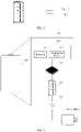
- the terminal device includes a processor and a charging/discharging protection circuit, where the charging/discharging protection circuit includes a power supply end, a grounding end, and an under-voltage protection threshold control end, where the power supply end is connected to a positive electrode of a battery, the grounding end is connected to a negative electrode of the battery, and the under-voltage protection threshold control end is connected to the processor.
- the processor is configured to: when a temperature of the battery is smaller than a set temperature threshold and a discharging current of the battery is greater than a set current threshold, reduce a discharging cutoff voltage of the battery and send a first control signal; and the charging/discharging protection circuit is configured to receive the first control signal through the under-voltage protection threshold control end and reduce an under-voltage protection threshold of the battery under the control of the first control signal.
- the terminal device when the temperature of the battery is smaller than the set temperature threshold and the discharging current of the battery is greater than the set current threshold, the terminal device reduces the under-voltage protection threshold of the battery and the discharging cutoff voltage of the battery, to enable the battery to continue to discharge, until the output voltage of the battery is smaller than the reduced under-voltage protection threshold; and therefore, before the under-voltage protection threshold of the battery is adjusted, the electric quantity in the battery that cannot continue to be used because of the low temperature can be released, so that the terminal device may continue to work, thereby improving the endurance capability of the terminal device.
- the processor is further configured to: when an output voltage of the battery is smaller than the discharging cutoff voltage of the battery, control the terminal device to be powered off, increase the discharging cutoff voltage of the battery, and send a second control signal; and the charging/discharging protection circuit is further configured to increase the under-voltage protection threshold of the battery under the control of the second control signal.
- the electric energy in the battery is still consumed after the terminal device is powered off. If the under-voltage protection threshold and the discharging cutoff voltage of the battery are increased when the terminal device is powered off, the battery can be prevented from being damaged, thereby ensuring the service life and the service safety of the battery. If the under-voltage protection threshold of the battery and the discharging cutoff voltage of the battery are not increased, the battery may be damaged in a scenario where the battery cannot be charged in time.
- the charging/discharging protection circuit further includes a discharging control end.
- the charging/discharging protection circuit is further configured to: compare the output voltage of the battery and the under-voltage protection threshold of the battery and output a third control signal through the discharging control end according to a comparison result, where the third control signal is used for controlling a discharging loop of the battery to be switched on or switched off.
- the third control signal is used for controlling the discharging loop of the battery to be switched on; and when the output voltage of the battery is smaller than the under-voltage protection threshold of the battery, the third control signal is used for controlling the discharging loop of the battery to be switched off, to perform under-voltage protection.
- the charging/discharging protection circuit includes a battery voltage sampling circuit, a reference voltage circuit, and a comparator, where the battery sampling circuit is connected to each of the power supply end, the grounding end, the under-voltage protection threshold control end, and a first input end of the comparator, the reference voltage circuit is connected to a second input end of the comparator, and an output end of the comparator is connected to the discharging control end.
- the battery voltage sampling circuit is configured to sample the output voltage of the battery and increase a sampling voltage under the control of the first control signal; an output voltage of the reference voltage circuit is used for representing the under-voltage protection threshold of the battery; and the comparator is configured to compare the output voltage of the reference voltage circuit and the increased sampling voltage and output the third control signal according to a comparison result.
- the battery voltage sampling circuit includes a first voltage divider resistor, a second voltage divider resistor, and a switch resistor array
- the switch resistor array includes a plurality of branches connected to each other in parallel, and each branch includes a third voltage divider resistor and a switch connected to the third voltage divider resistor in series.
- a first end of the first voltage divider resistor is connected to each of the power supply end and a first end of the switch resistor array, a second end of the first voltage divider resistor is connected to each of a first end of the second voltage divider resistor, a second end of the switch resistor array, and the first input end of the comparator, control ends of switches in the switch resistor array are connected to the under-voltage protection threshold control end, and a second end of the second voltage divider resistor is connected to the grounding end; and the first control signal is used for controlling at least one switch in the switch resistor array to switch from a switched-off state to a switched-on state.
- the reference voltage circuit is a voltage source.
- the charging/discharging protection circuit includes a battery voltage sampling circuit, a reference voltage circuit, and a comparator, where the battery sampling circuit is connected to each of the power supply end, the grounding end, and a first input end of the comparator, the reference voltage circuit is connected to each of a second input end of the comparator and the under-voltage protection threshold control end, and an output end of the comparator is connected to the discharging control end.
- the battery voltage sampling circuit is configured to sample the voltage of the battery; the reference voltage circuit is configured to reduce an output voltage of the reference voltage circuit under the control of the first control signal, where the output voltage of the reference voltage circuit is used for representing the under-voltage protection threshold of the battery; and the comparator is configured to compare an output voltage of the battery voltage sampling circuit and the output voltage of the reference voltage circuit and output the third control signal according to a comparison result.
- the battery voltage sampling circuit includes a first sampling resistor and a second sampling resistor.
- a first end of the first voltage divider resistor is connected to the power supply end, a second end of the first voltage divider resistor is connected to each of a first end of the second voltage divider resistor and the first input end of the comparator, and a second end of the second voltage divider resistor is connected to the grounding end.
- the reference voltage circuit includes a plurality of branches connected to each other in parallel, and each branch includes a voltage source and a switch connected to the voltage source in series.
- a first end of the reference voltage circuit is grounded, a second end of the reference voltage circuit is connected to the second input end of the comparator, and control ends of the switches in the reference voltage circuit are connected to the under-voltage protection threshold control end; and the first control signal is used for controlling a first switch in the reference voltage circuit to switch from a switched-on state to a switched-off state and controlling a second switch in the reference voltage circuit to switch from a switched-off state to a switched-on state, and a voltage of a voltage source connected to the first switch in series is greater than a voltage of a voltage source connected to the second switch in series.
- this application further provides a charging/discharging protection circuit.
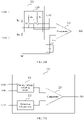
- the charging/discharging protection circuit includes: a power supply end, a grounding end, a temperature sampling end, a current sampling end, a controller, and an under-voltage protection control circuit, where the power supply end is connected to a positive electrode of the battery, the grounding end is connected to a negative electrode of the battery, and the controller is connected to each of the under-voltage protection control circuit, the temperature sampling end, and the current sampling end.
- the controller is configured to obtain a temperature of the battery through the temperature sampling end and obtain a discharging current of the battery through the current sampling end; and send a first control signal when the temperature of the battery is smaller than a set temperature threshold and the discharging current of the battery is greater than a set current threshold; and the under-voltage protection control circuit is configured to reduce an under-voltage protection threshold of the battery under the control of the first control signal.
- the charging/discharging protection circuit reduces the under-voltage protection threshold of the battery, to enable the battery to continue to discharge, until the output voltage of the battery is smaller than the reduced under-voltage protection threshold; and therefore, before the under-voltage protection threshold of the battery is adjusted, the electric quantity in the battery that cannot continue to be used because of the low temperature can be released and utilized by a power consumption load connected to the charging/discharging protection circuit.
- the controller is further configured to send a second control signal when an output voltage of the battery is smaller than a discharging cutoff voltage of the battery; and the under-voltage protection control circuit is further configured to increase the under-voltage protection threshold of the battery under the control of the second control signal.
- the under-voltage protection threshold of the battery is increased to prevent the battery from being damaged, thereby ensuring the service life and the service safety of the battery. If the under-voltage protection threshold of the battery is not increased, the battery may be damaged in a scenario where the battery cannot be charged in time.
- the charging/discharging protection circuit further includes a discharging control end, where the discharging control end is connected to the under-voltage protection control circuit.
- the under-voltage protection control circuit is further configured to: compare the output voltage of the battery and the under-voltage protection threshold of the battery and output a third control signal through the discharging control end according to a comparison result, where the third control signal is used for controlling a discharging loop of the battery to be switched on or switched off.
- the third control signal is used for controlling the discharging loop of the battery to be switched on; and when the output voltage of the battery is smaller than the under-voltage protection threshold of the battery, the third control signal is used for controlling the discharging loop of the battery to be switched off, to perform under-voltage protection.
- the under-voltage protection control circuit includes a battery voltage sampling circuit, a reference voltage circuit, and a comparator, where the battery sampling circuit is connected to each of the power supply end, the grounding end, the under-voltage protection threshold control end, and a first input end of the comparator, the reference voltage circuit is connected to a second input end of the comparator, and an output end of the comparator is connected to the discharging control end.
- the battery voltage sampling circuit is configured to sample the output voltage of the battery and increase a sampling voltage under the control of the first control signal; an output voltage of the reference voltage circuit is used for representing the under-voltage protection threshold of the battery; and the comparator is configured to compare the output voltage of the reference voltage circuit and the increased sampling voltage and output the third control signal according to a comparison result.
- the battery voltage sampling circuit includes a first voltage divider resistor, a second voltage divider resistor, and a switch resistor array
- the switch resistor array includes a plurality of branches connected to each other in parallel, and each branch includes a third voltage divider resistor and a switch connected to the third voltage divider resistor in series.
- a first end of the first voltage divider resistor is connected to each of the power supply end and a first end of the switch resistor array, a second end of the first voltage divider resistor is connected to each of a first end of the second voltage divider resistor, a second end of the switch resistor array, and the first input end of the comparator, control ends of switches in the switch resistor array are connected to the under-voltage protection threshold control end, and a second end of the second voltage divider resistor is connected to the grounding end; and the first control signal is used for controlling at least one switch in the switch resistor array to switch from a switched-off state to a switched-on state.
- the reference voltage circuit is a voltage source.
- the under-voltage protection control circuit includes a battery voltage sampling circuit, a reference voltage circuit, and a comparator, where the battery sampling circuit is connected to each of the power supply end, the grounding end, and a first input end of the comparator, and the reference voltage circuit is connected to each of a second input end of the comparator and the under-voltage protection threshold control end.
- the battery voltage sampling circuit is configured to sample the output voltage of the battery; the reference voltage circuit is configured to reduce an output voltage of the reference voltage circuit under the control of the first control signal; and an output voltage of the reference voltage circuit is used for representing the under-voltage protection threshold of the battery; and the comparator is configured to compare the output voltage of the reference voltage circuit and an output voltage of the battery voltage sampling circuit and output the third control signal according to a comparison result.
- the battery voltage sampling circuit includes a first sampling resistor and a second sampling resistor.
- a first end of the first voltage divider resistor is connected to the power supply end, a second end of the first voltage divider resistor is connected to each of a first end of the second voltage divider resistor and the first input end of the comparator, and a second end of the second voltage divider resistor is connected to the grounding end.
- the reference voltage circuit includes a plurality of branches connected to each other in parallel, and each branch includes a voltage source and a switch connected to the voltage source in series.
- a first end of the reference voltage circuit is grounded, a second end of the reference voltage circuit is connected to the second input end of the comparator, and control ends of the switches in the reference voltage circuit are connected to the under-voltage protection threshold control end; and the first control signal is used for controlling a first switch in the reference voltage circuit to switch from a switched-on state to a switched-off state and controlling a second switch in the reference voltage circuit to switch from a switched-off state to a switched-on state, and a voltage of a voltage source connected to the first switch in series is greater than a voltage of a voltage source connected to the second switch in series.
- this application further provides a terminal device.
- the terminal device includes a processor and a charging/discharging protection circuit.
- the processor is configured to reduce a discharging cutoff voltage of a battery connected to the charging/discharging protection circuit when a temperature of the battery is smaller than a set temperature threshold and a discharging current of the battery is greater than a set current threshold; and the charging/discharging protection circuit is configured to reduce an under-voltage protection threshold of the battery when the temperature of the battery is smaller than a set temperature threshold and the discharging current of the battery is greater than a set current threshold.
- the terminal device when the temperature of the battery is smaller than the set temperature threshold and the discharging current of the battery is greater than the set current threshold, the terminal device reduces the under-voltage protection threshold of the battery and the discharging cutoff voltage of the battery, to enable the battery to continue to discharge, until the output voltage of the battery is smaller than the reduced under-voltage protection threshold; and therefore, before the under-voltage protection threshold of the battery is adjusted, the electric quantity in the battery that cannot continue to be used because of the low temperature can be released, so that the terminal device may continue to work, thereby improving the endurance capability of the terminal device.
- the processor is further configured to: when an output voltage of the battery is smaller than the discharging cutoff voltage of the battery, control the terminal device to be powered off, and increase the discharging cutoff voltage of the battery; and the charging/discharging protection circuit is further configured to increase the under-voltage protection threshold of the battery when an output voltage of the battery is smaller than a discharging cutoff voltage of the battery and after the terminal device is powered off.
- the electric energy in the battery is still consumed after the terminal device is powered off. If the under-voltage protection threshold and the discharging cutoff voltage of the battery are increased when the terminal device is powered off, the battery can be prevented from being damaged, thereby ensuring the service life and the service safety of the battery. If the under-voltage protection threshold of the battery and the discharging cutoff voltage of the battery are not increased, the battery may be damaged in a scenario where the battery cannot be charged in time.
- the charging/discharging protection circuit includes: a power supply end, a grounding end, a temperature sampling end, a current sampling end, a controller, and an under-voltage protection control circuit, where the power supply end is connected to a positive electrode of the battery, the grounding end is connected to a negative electrode of the battery, and the controller is connected to each of the under-voltage protection control circuit, the temperature sampling end, and the current sampling end.
- the controller is configured to obtain a temperature of the battery through the temperature sampling end and obtain a discharging current of the battery through the current sampling end; and send a first control signal when the temperature of the battery is smaller than a set temperature threshold and the discharging current of the battery is greater than a set current threshold; and the under-voltage protection control circuit is configured to reduce an under-voltage protection threshold of the battery under the control of the first control signal.
- the charging/discharging protection circuit further includes a discharging control end.
- the under-voltage protection control circuit is further configured to: compare the output voltage of the battery and the under-voltage protection threshold of the battery and output a third control signal through the discharging control end according to a comparison result, where the third control signal is used for controlling a discharging loop of the battery to be switched on or switched off.
- the under-voltage protection control circuit includes a battery voltage sampling circuit, a reference voltage circuit, and a comparator, where the battery sampling circuit is connected to each of the power supply end, the grounding end, the under-voltage protection threshold control end, and a first input end of the comparator, the reference voltage circuit is connected to a second input end of the comparator, and an output end of the comparator is connected to the discharging control end.
- the battery voltage sampling circuit is configured to sample the output voltage of the battery and increase a sampling voltage under the control of the first control signal; an output voltage of the reference voltage circuit is used for representing the under-voltage protection threshold of the battery; and the comparator is configured to compare the output voltage of the reference voltage circuit and the increased sampling voltage and output the third control signal according to a comparison result.
- the battery voltage sampling circuit includes a first voltage divider resistor, a second voltage divider resistor, and a switch resistor array
- the switch resistor array includes a plurality of branches connected to each other in parallel, and each branch includes a third voltage divider resistor and a switch connected to the third voltage divider resistor in series.
- a first end of the first voltage divider resistor is connected to each of the power supply end and a first end of the switch resistor array, a second end of the first voltage divider resistor is connected to each of a first end of the second voltage divider resistor, a second end of the switch resistor array, and the first input end of the comparator, control ends of switches in the switch resistor array are connected to the under-voltage protection threshold control end, and a second end of the second voltage divider resistor is connected to the grounding end; and the first control signal is used for controlling at least one switch in the switch resistor array to switch from a switched-off state to a switched-on state.
- the reference voltage circuit is a voltage source.
- the under-voltage protection control circuit includes a battery voltage sampling circuit, a reference voltage circuit, and a comparator, where the battery sampling circuit is connected to each of the power supply end, the grounding end, and a first input end of the comparator, the reference voltage circuit is connected to each of a second input end of the comparator and the under-voltage protection threshold control end, and an output end of the comparator is connected to the discharging control end.
- the battery voltage sampling circuit is configured to sample the voltage of the battery; the reference voltage circuit is configured to reduce an output voltage of the reference voltage circuit under the control of the first control signal, where the output voltage of the reference voltage circuit is used for representing the under-voltage protection threshold of the battery; and the comparator is configured to compare the output voltage of the reference voltage circuit and an output voltage of the battery voltage sampling circuit and output the third control signal according to a comparison result.
- the battery voltage sampling circuit includes a first sampling resistor and a second sampling resistor, where a first end of the first voltage divider resistor is connected to the power supply end, a second end of the first voltage divider resistor is connected to each of a first end of the second voltage divider resistor and the first input end of the comparator, and a second end of the second voltage divider resistor is connected to the grounding end.
- the reference voltage circuit includes a plurality of branches connected to each other in parallel, and each branch includes a voltage source and a switch connected to the voltage source in series.
- a first end of the reference voltage circuit is grounded, a second end of the reference voltage circuit is connected to the second input end of the comparator, and control ends of the switches in the reference voltage circuit are connected to the under-voltage protection threshold control end; and the first control signal is used for controlling a first switch in the reference voltage circuit to switch from a switched-on state to a switched-off state and controlling a second switch in the reference voltage circuit to switch from a switched-off state to a switched-on state, and a voltage of a voltage source connected to the first switch in series is greater than a voltage of a voltage source connected to the second switch in series.
- this application further provides a battery discharging control method.
- the method includes: detecting, by a terminal device, a temperature of a battery in the terminal device and a discharging current of the battery; and reducing an under-voltage protection threshold of the battery and a discharging cutoff voltage of the battery when the temperature of the battery is smaller than a set temperature threshold and the discharging current of the battery is greater than a set current threshold.
- the terminal device when the temperature of the battery is smaller than the set temperature threshold and the discharging current of the battery is greater than the set current threshold, the terminal device reduces the under-voltage protection threshold of the battery and the discharging cutoff voltage of the battery, to enable the battery to continue to discharge, until the output voltage of the battery is smaller than the reduced under-voltage protection threshold; and therefore, before the under-voltage protection threshold of the battery is adjusted, the electric quantity in the battery that cannot continue to be used because of the low temperature can be released, so that the terminal device may continue to work, thereby improving the endurance capability of the terminal device.
- the terminal device controls the terminal device to be powered off, and increases the under-voltage protection threshold of the battery and the discharging cutoff voltage of the battery.
- the electric energy in the battery is still consumed after the terminal device is powered off. If the under-voltage protection threshold and the discharging cutoff voltage of the battery are increased when the terminal device is powered off, the battery can be prevented from being damaged, thereby ensuring the service life and the service safety of the battery. If the under-voltage protection threshold of the battery and the discharging cutoff voltage of the battery are not increased, the battery may be damaged in a scenario where the battery cannot be charged in time.
- the terminal device further compares the output voltage of the battery and the under-voltage protection threshold of the battery, and controls, according to a comparison result, a discharging loop of the battery to be switched on or switched off.
- the terminal device controls the discharging loop of the battery to be switched on; and when the output voltage of the battery is smaller than the under-voltage protection threshold of the battery, the terminal device controls the discharging loop of the battery to be switched off, to perform under-voltage protection.
- this application further provides a battery discharging control method.
- the method includes: receiving, by a charging/discharging protection circuit, a first control signal when a temperature of a battery connected to the charging protection circuit is smaller than a set temperature threshold and a discharging current of the battery is greater than a set current threshold, and reducing an under-voltage protection threshold of the battery under the control of the first control signal.
- the charging/discharging protection circuit reduces the under-voltage protection threshold of the battery, to enable the battery to continue to discharge, until the output voltage of the battery is smaller than the reduced under-voltage protection threshold; and therefore, before the under-voltage protection threshold of the battery is adjusted, the electric quantity in the battery that cannot continue to be used because of the low temperature can be released and utilized by a power consumption load connected to the charging/discharging protection circuit.
- the charging/discharging protection circuit further receives a second control signal when an output voltage of the battery is smaller than a discharging cutoff voltage of the battery and increases the under-voltage protection threshold of the battery under the control of the second control signal.
- the under-voltage protection threshold of the battery is increased to prevent the battery from being damaged, thereby ensuring the service life and the service safety of the battery. If the under-voltage protection threshold of the battery is not increased, the battery may be damaged in a scenario where the battery cannot be charged in time.
- the charging/discharging protection circuit further compares the output voltage of the battery and the under-voltage protection threshold of the battery and outputs a third control signal according to a comparison result, where the third control signal is used for controlling a discharging loop of the battery to be switched off or switched on.
- the third control signal is used for controlling the discharging loop of the battery to be switched on; and when the output voltage of the battery is smaller than the under-voltage protection threshold of the battery, the third control signal is used for controlling the discharging loop of the battery to be switched off, to perform under-voltage protection.
- this application further provides a battery discharging control method.
- the method includes: obtaining, by a charging/discharging protection circuit, a temperature of a battery connected to the charging protection circuit and a discharging current of the battery, and reducing an under-voltage protection threshold of the battery when the temperature of the battery is smaller than a set temperature threshold and the discharging current of the battery is greater than a set current threshold.
- the charging/discharging protection circuit reduces the under-voltage protection threshold of the battery, to enable the battery to continue to discharge, until the output voltage of the battery is smaller than the reduced under-voltage protection threshold; and therefore, before the under-voltage protection threshold of the battery is adjusted, the electric quantity in the battery that cannot continue to be used because of the low temperature can be released and utilized by a power consumption load connected to the charging/discharging protection circuit.
- the charging/discharging protection circuit further increases the under-voltage protection threshold of the battery when an output voltage of the battery is smaller than a discharging cutoff voltage of the battery.
- the under-voltage protection threshold of the battery is increased to prevent the battery from being damaged, thereby ensuring the service life and the service safety of the battery. If the under-voltage protection threshold of the battery is not increased, the battery may be damaged in a scenario where the battery cannot be charged in time.
- the charging/discharging protection circuit further compares the output voltage of the battery and the under-voltage protection threshold of the battery and outputs a third control signal according to a comparison result, where the third control signal is used for controlling a discharging loop of the battery to be switched off or switched on.
- the third control signal is used for controlling the discharging loop of the battery to be switched on; and when the output voltage of the battery is smaller than the under-voltage protection threshold of the battery, the third control signal is used for controlling the discharging loop of the battery to be switched off, to perform under-voltage protection.
- this application further provides a charging/discharging protection circuit.
- the charging/discharging protection circuit includes a power supply end, a grounding end, and an under-voltage protection threshold control end; the power supply end is connected to a positive electrode of a battery; the grounding end is connected to a negative electrode of the battery; the under-voltage protection threshold control end is configured to receive a first control signal.
- the charging/discharging protection circuit is configured to reduce an under-voltage protection threshold of the battery under the control of the first control signal when a quantity of charging/discharging cycles of the battery is greater than a set quantity and a discharging current of the battery is greater than a set current threshold.
- the charging/discharging protection circuit reduces the under-voltage protection threshold of the battery, to enable the battery to continue to discharge, until the output voltage of the battery is smaller than the reduced under-voltage protection threshold; and therefore, before the under-voltage protection threshold of the battery is adjusted, the electric quantity in the battery that cannot continue to be used because of the aging can be released and utilized by a power consumption load connected to the charging/discharging protection circuit.
- the under-voltage protection threshold control end is further configured to receive a second control signal; and the charging/discharging protection circuit is further configured to increase the under-voltage protection threshold of the battery under the control of the second control signal when an output voltage of the battery is smaller than a discharging cutoff voltage of the battery.
- the under-voltage protection threshold of the battery is increased to prevent the battery from being damaged, thereby ensuring the service life and the service safety of the battery. If the under-voltage protection threshold of the battery is not increased, the battery may be damaged in a scenario where the battery cannot be charged in time.
- the charging/discharging protection circuit further includes a discharging control end, where the discharging control end is configured to output a third control signal.
- the charging/discharging protection circuit is further configured to: compare the output voltage of the battery and the under-voltage protection threshold of the battery and output the third control signal according to a comparison result, where the third control signal is used for controlling a discharging loop of the battery to be switched on or switched off.
- the third control signal is used for controlling the discharging loop of the battery to be switched on; and when the output voltage of the battery is smaller than the under-voltage protection threshold of the battery, the third control signal is used for controlling the discharging loop of the battery to be switched off, to perform under-voltage protection.
- the charging/discharging protection circuit includes a battery voltage sampling circuit, a reference voltage circuit, and a comparator, where the battery sampling circuit is connected to each of the power supply end, the grounding end, the under-voltage protection threshold control end, and a first input end of the comparator, the reference voltage circuit is connected to a second input end of the comparator, and an output end of the comparator is connected to the discharging control end.
- the battery voltage sampling circuit is configured to sample the output voltage of the battery and increase a sampling voltage under the control of the first control signal; an output voltage of the reference voltage circuit is used for representing the under-voltage protection threshold of the battery; and the comparator is configured to compare the output voltage of the reference voltage circuit and the increased sampling voltage and output the third control signal according to a comparison result.
- the battery voltage sampling circuit includes a first voltage divider resistor, a second voltage divider resistor, and a switch resistor array
- the switch resistor array includes a plurality of branches connected to each other in parallel, and each branch includes a third voltage divider resistor and a switch connected to the third voltage divider resistor in series.
- a first end of the first voltage divider resistor is connected to each of the power supply end and a first end of the switch resistor array, a second end of the first voltage divider resistor is connected to each of a first end of the second voltage divider resistor, a second end of the switch resistor array, and the first input end of the comparator, control ends of switches in the switch resistor array are connected to the under-voltage protection threshold control end, and a second end of the second voltage divider resistor is connected to the grounding end; and the first control signal is used for controlling at least one switch in the switch resistor array to switch from a switched-off state to a switched-on state.
- the reference voltage circuit is a voltage source.
- the charging/discharging protection circuit includes a battery voltage sampling circuit, a reference voltage circuit, and a comparator, where the battery sampling circuit is connected to each of the power supply end, the grounding end, and a first input end of the comparator, and the reference voltage circuit is connected to each of a second input end of the comparator and the under-voltage protection threshold control end.
- the battery voltage sampling circuit is configured to sample the output voltage of the battery; the reference voltage circuit is configured to reduce an output voltage of the reference voltage circuit under the control of the first control signal; and an output voltage of the reference voltage circuit is used for representing the under-voltage protection threshold of the battery; and the comparator is configured to compare the output voltage of the reference voltage circuit and an output voltage of the battery voltage sampling circuit and output the third control signal according to a comparison result.
- the battery voltage sampling circuit includes a first sampling resistor and a second sampling resistor.
- a first end of the first voltage divider resistor is connected to the power supply end, a second end of the first voltage divider resistor is connected to each of a first end of the second voltage divider resistor and the first input end of the comparator, and a second end of the second voltage divider resistor is connected to the grounding end.
- the reference voltage circuit includes a plurality of branches connected to each other in parallel, and each branch includes a voltage source and a switch connected to the voltage source in series.
- a first end of the reference voltage circuit is grounded, a second end of the reference voltage circuit is connected to the second input end of the comparator, and control ends of the switches in the reference voltage circuit are connected to the under-voltage protection threshold control end; and the first control signal is used for controlling a first switch in the reference voltage circuit to switch from a switched-on state to a switched-off state and controlling a second switch in the reference voltage circuit to switch from a switched-off state to a switched-on state, and a voltage of a voltage source connected to the first switch in series is greater than a voltage of a voltage source connected to the second switch in series.
- this application further provides a terminal device.
- the terminal device includes a processor and a charging/discharging protection circuit, where the charging/discharging protection circuit includes a power supply end, a grounding end, and an under-voltage protection threshold control end, where the power supply end is connected to a positive electrode of a battery, the grounding end is connected to a negative electrode of the battery, and the under-voltage protection threshold control end is connected to the processor.
- the processor is configured to: when a quantity of charging/discharging cycles of the battery is greater than a set quantity and a discharging current of the battery is greater than a set current threshold, reduce a discharging cutoff voltage of the battery and send a first control signal; and the charging/discharging protection circuit is configured to reduce an under-voltage protection threshold of the battery under the control of the first control signal.
- the terminal device when the quantity of charging/discharging cycles of the battery is greater than the set quantity, that is, the battery is aging, and the discharging current of the battery is greater than the set current threshold, the terminal device reduces the under-voltage protection threshold of the battery and the discharging cutoff voltage of the battery, to enable the battery to continue to discharge, until the output voltage of the battery is smaller than the reduced under-voltage protection threshold; and therefore, before the under-voltage protection threshold of the battery is adjusted, the electric quantity in the battery that cannot continue to be used because of the aging can be released, so that the terminal device may continue to work, thereby improving the endurance capability of the terminal device.
- the processor is further configured to: when an output voltage of the battery is smaller than the discharging cutoff voltage of the battery, control the terminal device to be powered off, increase the discharging cutoff voltage of the battery, and send a second control signal; and the charging/discharging protection circuit is further configured to increase the under-voltage protection threshold of the battery under the control of the second voltage signal.
- the electric energy in the battery is still consumed after the terminal device is powered off. If the under-voltage protection threshold and the discharging cutoff voltage of the battery are increased when the terminal device is powered off, the battery can be prevented from being damaged, thereby ensuring the service life and the service safety of the battery. If the under-voltage protection threshold of the battery and the discharging cutoff voltage of the battery are not increased, the battery may be damaged in a scenario where the battery cannot be charged in time.
- the charging/discharging protection circuit further includes a discharging control end.
- the charging/discharging protection circuit is further configured to: compare the output voltage of the battery and the under-voltage protection threshold of the battery and output a third control signal through the discharging control end according to a comparison result, where the third control signal is used for controlling a discharging loop of the battery to be switched on or switched off.
- the third control signal is used for controlling the discharging loop of the battery to be switched on; and when the output voltage of the battery is smaller than the under-voltage protection threshold of the battery, the third control signal is used for controlling the discharging loop of the battery to be switched off, to perform under-voltage protection.
- the charging/discharging protection circuit includes a battery voltage sampling circuit, a reference voltage circuit, and a comparator, where the battery sampling circuit is connected to each of the power supply end, the grounding end, the under-voltage protection threshold control end, and a first input end of the comparator, the reference voltage circuit is connected to a second input end of the comparator, and an output end of the comparator is connected to the discharging control end.
- the battery voltage sampling circuit is configured to sample the output voltage of the battery and increase a sampling voltage under the control of the first control signal; an output voltage of the reference voltage circuit is used for representing the under-voltage protection threshold of the battery; and the comparator is configured to compare the output voltage of the reference voltage circuit and the increased sampling voltage and output the third control signal according to a comparison result.
- the battery voltage sampling circuit includes a first voltage divider resistor, a second voltage divider resistor, and a switch resistor array
- the switch resistor array includes a plurality of branches connected to each other in parallel, and each branch includes a third voltage divider resistor and a switch connected to the third voltage divider resistor in series.
- a first end of the first voltage divider resistor is connected to each of the power supply end and a first end of the switch resistor array, a second end of the first voltage divider resistor is connected to each of a first end of the second voltage divider resistor, a second end of the switch resistor array, and the first input end of the comparator, control ends of switches in the switch resistor array are connected to the under-voltage protection threshold control end, and a second end of the second voltage divider resistor is connected to the grounding end; and the first control signal is used for controlling at least one switch in the switch resistor array to switch from a switched-off state to a switched-on state.
- the reference voltage circuit is a voltage source.
- the charging/discharging protection circuit includes a battery voltage sampling circuit, a reference voltage circuit, and a comparator, where the battery sampling circuit is connected to each of the power supply end, the grounding end, and a first input end of the comparator, the reference voltage circuit is connected to each of a second input end of the comparator and the under-voltage protection threshold control end, and an output end of the comparator is connected to the discharging control end.
- the battery voltage sampling circuit is configured to sample the voltage of the battery; the reference voltage circuit is configured to reduce an output voltage of the reference voltage circuit under the control of the first control signal, where the output voltage of the reference voltage circuit is used for representing the under-voltage protection threshold of the battery; and the comparator is configured to compare the output voltage of the reference voltage circuit and an output voltage of the battery voltage sampling circuit and output the third control signal according to a comparison result.
- the battery voltage sampling circuit includes a first sampling resistor and a second sampling resistor, where a first end of the first voltage divider resistor is connected to the power supply end, a second end of the first voltage divider resistor is connected to each of a first end of the second voltage divider resistor and the first input end of the comparator, and a second end of the second voltage divider resistor is connected to the grounding end.
- the reference voltage circuit includes a plurality of branches connected to each other in parallel, and each branch includes a voltage source and a switch connected to the voltage source in series.
- a first end of the reference voltage circuit is grounded, a second end of the reference voltage circuit is connected to the second input end of the comparator, and control ends of the switches in the reference voltage circuit are connected to the under-voltage protection threshold control end; and the first control signal is used for controlling a first switch in the reference voltage circuit to switch from a switched-on state to a switched-off state and controlling a second switch in the reference voltage circuit to switch from a switched-off state to a switched-on state, and a voltage of a voltage source connected to the first switch in series is greater than a voltage of a voltage source connected to the second switch in series.
- this application further provides a charging/discharging protection circuit.
- the charging/discharging protection circuit includes: a power supply end, a grounding end, a current sampling end, a controller, and an under-voltage protection control circuit, where the power supply end is connected to a positive electrode of the battery, the grounding end is connected to a negative electrode of the battery, and the controller is connected to each of the under-voltage protection control circuit and the current sampling end.
- the controller is configured to collect statistics on a quantity of charging/discharging cycles of the battery and obtain a discharging current of the battery through the current sampling end; and send a first control signal when the quantity of charging/discharging cycles of the battery is greater than a set quantity and the discharging current of the battery is greater than a set current threshold; and the under-voltage protection control circuit is configured to reduce an under-voltage protection threshold of the battery under the control of the first control signal.
- the charging/discharging protection circuit reduces the under-voltage protection threshold of the battery, to enable the battery to continue to discharge, until the output voltage of the battery is smaller than the reduced under-voltage protection threshold; and therefore, before the under-voltage protection threshold of the battery is adjusted, the electric quantity in the battery that cannot continue to be used because of the aging can be released and utilized by a power consumption load connected to the charging/discharging protection circuit.
- the controller is further configured to send a second control signal when an output voltage of the battery is smaller than a discharging cutoff voltage of the battery; and the under-voltage protection control circuit is further configured to increase the under-voltage protection threshold of the battery under the control of the second control signal.
- the under-voltage protection threshold of the battery is increased to prevent the battery from being damaged, thereby ensuring the service life and the service safety of the battery. If the under-voltage protection threshold of the battery is not increased, the battery may be damaged in a scenario where the battery cannot be charged in time.
- the charging/discharging protection circuit further includes a discharging control end, where the discharging control end is connected to the under-voltage protection control circuit.
- the under-voltage protection control circuit is further configured to: compare the output voltage of the battery and the under-voltage protection threshold of the battery and output a third control signal through the discharging control end according to a comparison result, where the third control signal is used for controlling a discharging loop of the battery to be switched on or switched off.
- the third control signal is used for controlling the discharging loop of the battery to be switched on; and when the output voltage of the battery is smaller than the under-voltage protection threshold of the battery, the third control signal is used for controlling the discharging loop of the battery to be switched off, to perform under-voltage protection.
- the under-voltage protection control circuit includes a battery voltage sampling circuit, a reference voltage circuit, and a comparator, where the battery sampling circuit is connected to each of the power supply end, the grounding end, the under-voltage protection threshold control end, and a first input end of the comparator, the reference voltage circuit is connected to a second input end of the comparator, and an output end of the comparator is connected to the discharging control end.
- the battery voltage sampling circuit is configured to sample the output voltage of the battery and increase a sampling voltage under the control of the first control signal; an output voltage of the reference voltage circuit is used for representing the under-voltage protection threshold of the battery; and the comparator is configured to compare the output voltage of the reference voltage circuit and the increased sampling voltage and output the third control signal according to a comparison result.
- the battery voltage sampling circuit includes a first voltage divider resistor, a second voltage divider resistor, and a switch resistor array
- the switch resistor array includes a plurality of branches connected to each other in parallel, and each branch includes a third voltage divider resistor and a switch connected to the third voltage divider resistor in series.
- a first end of the first voltage divider resistor is connected to each of the power supply end and a first end of the switch resistor array, a second end of the first voltage divider resistor is connected to each of a first end of the second voltage divider resistor, a second end of the switch resistor array, and the first input end of the comparator, control ends of switches in the switch resistor array are connected to the under-voltage protection threshold control end, and a second end of the second voltage divider resistor is connected to the grounding end; and the first control signal is used for controlling at least one switch in the switch resistor array to switch from a switched-off state to a switched-on state.
- the reference voltage circuit is a voltage source.
- the under-voltage protection control circuit includes a battery voltage sampling circuit, a reference voltage circuit, and a comparator, where the battery sampling circuit is connected to each of the power supply end, the grounding end, and a first input end of the comparator, and the reference voltage circuit is connected to each of a second input end of the comparator and the under-voltage protection threshold control end.
- the battery voltage sampling circuit is configured to sample the output voltage of the battery; the reference voltage circuit is configured to reduce an output voltage of the reference voltage circuit under the control of the first control signal, where the output voltage of the reference voltage circuit is used for representing the under-voltage protection threshold of the battery; and the comparator is configured to compare the output voltage of the reference voltage circuit and an output voltage of the battery voltage sampling circuit and output the third control signal according to a comparison result.
- the battery voltage sampling circuit includes a first sampling resistor and a second sampling resistor.
- a first end of the first voltage divider resistor is connected to the power supply end, a second end of the first voltage divider resistor is connected to each of a first end of the second voltage divider resistor and the first input end of the comparator, and a second end of the second voltage divider resistor is connected to the grounding end.
- the reference voltage circuit includes a plurality of branches connected to each other in parallel, and each branch includes a voltage source and a switch connected to the voltage source in series.
- a first end of the reference voltage circuit is grounded, a second end of the reference voltage circuit is connected to the second input end of the comparator, and control ends of the switches in the reference voltage circuit are connected to the under-voltage protection threshold control end; and the first control signal is used for controlling a first switch in the reference voltage circuit to switch from a switched-on state to a switched-off state and controlling a second switch in the reference voltage circuit to switch from a switched-off state to a switched-on state, and a voltage of a voltage source connected to the first switch in series is greater than a voltage of a voltage source connected to the second switch in series.
- this application further provides a terminal device.
- the terminal device includes a processor and a charging/discharging protection circuit.
- the processor is configured to reduce a discharging cutoff voltage of a battery connected to the charging/discharging protection circuit when a quantity of charging/discharging cycles of the battery is greater than a set quantity and a discharging current of the battery is greater than a set current threshold; and the charging/discharging protection circuit is configured to reduce an under-voltage protection threshold of the battery when the quantity of charging/discharging cycles of the battery is greater than the set quantity and the discharging current of the battery is greater than the set current threshold.
- the terminal device when the quantity of charging/discharging cycles of the battery is greater than the set quantity, that is, the battery is aging, and the discharging current of the battery is greater than the set current threshold, the terminal device reduces the under-voltage protection threshold of the battery and the discharging cutoff voltage of the battery, to enable the battery to continue to discharge, until the output voltage of the battery is smaller than the reduced under-voltage protection threshold; and therefore, before the under-voltage protection threshold of the battery is adjusted, the electric quantity in the battery that cannot continue to be used because of the aging can be released, so that the terminal device may continue to work, thereby improving the endurance capability of the terminal device.
- the processor is further configured to: when an output voltage of the battery is smaller than the discharging cutoff voltage of the battery, control the terminal device to be powered off, and increase the discharging cutoff voltage of the battery; and the charging/discharging protection circuit is further configured to increase the under-voltage protection threshold of the battery when an output voltage of the battery is smaller than a discharging cutoff voltage of the battery and after the terminal device is powered off.
- the electric energy in the battery is still consumed after the terminal device is powered off. If the under-voltage protection threshold and the discharging cutoff voltage of the battery are increased when the terminal device is powered off, the battery can be prevented from being damaged, thereby ensuring the service life and the service safety of the battery. If the under-voltage protection threshold of the battery and the discharging cutoff voltage of the battery are not increased, the battery may be damaged in a scenario where the battery cannot be charged in time.
- the charging/discharging protection circuit includes: a power supply end, a grounding end, a current sampling end, a controller, and an under-voltage protection control circuit, where the power supply end is connected to a positive electrode of the battery, the grounding end is connected to a negative electrode of the battery, and the controller is connected to each of the under-voltage protection control circuit and the current sampling end.
- the controller is configured to collect statistics on a quantity of charging/discharging cycles of the battery and obtain a discharging current of the battery through the current sampling end; and send a first control signal when the quantity of charging/discharging cycles of the battery is greater than a set quantity and the discharging current of the battery is greater than a set current threshold; and the under-voltage protection control circuit is configured to reduce an under-voltage protection threshold of the battery under the control of the first control signal.
- the charging/discharging protection circuit further includes a discharging control end.
- the charging/discharging protection circuit is further configured to: compare the output voltage of the battery and the under-voltage protection threshold of the battery and output a third control signal through the discharging control end according to a comparison result, where the third control signal is used for controlling a discharging loop of the battery to be switched on or switched off.
- the third control signal is used for controlling the discharging loop of the battery to be switched on; and when the output voltage of the battery is smaller than the under-voltage protection threshold of the battery, the third control signal is used for controlling the discharging loop of the battery to be switched off, to perform under-voltage protection.
- the under-voltage protection control circuit includes a battery voltage sampling circuit, a reference voltage circuit, and a comparator, where the battery sampling circuit is connected to each of the power supply end, the grounding end, the under-voltage protection threshold control end, and a first input end of the comparator, the reference voltage circuit is connected to a second input end of the comparator, and an output end of the comparator is connected to the discharging control end.
- the battery voltage sampling circuit is configured to sample the output voltage of the battery and increase a sampling voltage under the control of the first control signal; an output voltage of the reference voltage circuit is used for representing the under-voltage protection threshold of the battery; and the comparator is configured to compare the output voltage of the reference voltage circuit and the increased sampling voltage and output the third control signal according to a comparison result.
- the battery voltage sampling circuit includes a first voltage divider resistor, a second voltage divider resistor, and a switch resistor array
- the switch resistor array includes a plurality of branches connected to each other in parallel, and each branch includes a third voltage divider resistor and a switch connected to the third voltage divider resistor in series.
- a first end of the first voltage divider resistor is connected to each of the power supply end and a first end of the switch resistor array, a second end of the first voltage divider resistor is connected to each of a first end of the second voltage divider resistor, a second end of the switch resistor array, and the first input end of the comparator, control ends of switches in the switch resistor array are connected to the under-voltage protection threshold control end, and a second end of the second voltage divider resistor is connected to the grounding end; and the first control signal is used for controlling at least one switch in the switch resistor array to switch from a switched-off state to a switched-on state.
- the reference voltage circuit is a voltage source.
- the under-voltage protection control circuit includes a battery voltage sampling circuit, a reference voltage circuit, and a comparator, where the battery sampling circuit is connected to each of the power supply end, the grounding end, and a first input end of the comparator, the reference voltage circuit is connected to each of a second input end of the comparator and the under-voltage protection threshold control end, and an output end of the comparator is connected to the discharging control end.
- the battery voltage sampling circuit is configured to sample the voltage of the battery; the reference voltage circuit is configured to reduce an output voltage of the reference voltage circuit under the control of the first control signal, where the output voltage of the reference voltage circuit is used for representing the under-voltage protection threshold of the battery; and the comparator is configured to compare the output voltage of the reference voltage circuit and an output voltage of the battery voltage sampling circuit and output the third control signal according to a comparison result.
- the battery voltage sampling circuit includes a first sampling resistor and a second sampling resistor.
- a first end of the first voltage divider resistor is connected to the power supply end, a second end of the first voltage divider resistor is connected to each of a first end of the second voltage divider resistor and the first input end of the comparator, and a second end of the second voltage divider resistor is connected to the grounding end.
- the reference voltage circuit includes a plurality of branches connected to each other in parallel, and each branch includes a voltage source and a switch connected to the voltage source in series.
- a first end of the reference voltage circuit is grounded, a second end of the reference voltage circuit is connected to the second input end of the comparator, and control ends of the switches in the reference voltage circuit are connected to the under-voltage protection threshold control end; and the first control signal is used for controlling a first switch in the reference voltage circuit to switch from a switched-on state to a switched-off state and controlling a second switch in the reference voltage circuit to switch from a switched-off state to a switched-on state, and a voltage of a voltage source connected to the first switch in series is greater than a voltage of a voltage source connected to the second switch in series.
- this application further provides a battery discharging control method.
- the method includes: detecting, by a terminal device, a discharging current of a battery in the terminal device, and collecting statistics on a quantity of charging/discharging cycles of the battery; and reducing an under-voltage protection threshold of the battery and a discharging cutoff voltage of the battery when the quantity of charging/discharging cycles of the battery is greater than a set quantity and the discharging current of the battery is greater than a set current threshold.
- the terminal device when the quantity of charging/discharging cycles of the battery is greater than the set quantity, that is, the battery is aging, and the discharging current of the battery is greater than the set current threshold, the terminal device reduces the under-voltage protection threshold of the battery and the discharging cutoff voltage of the battery, to enable the battery to continue to discharge, until the output voltage of the battery is smaller than the reduced under-voltage protection threshold; and therefore, before the under-voltage protection threshold of the battery is adjusted, the electric quantity in the battery that cannot continue to be used because of the aging can be released, so that the terminal device may continue to work, thereby improving the endurance capability of the terminal device.
- the terminal device controls the terminal device to be powered off, and increases the under-voltage protection threshold of the battery and the discharging cutoff voltage of the battery.
- the electric energy in the battery is still consumed after the terminal device is powered off. If the under-voltage protection threshold and the discharging cutoff voltage of the battery are increased when the terminal device is powered off, the battery can be prevented from being damaged, thereby ensuring the service life and the service safety of the battery. If the under-voltage protection threshold of the battery and the discharging cutoff voltage of the battery are not increased, the battery may be damaged in a scenario where the battery cannot be charged in time.
- the terminal device compares the output voltage of the battery and the under-voltage protection threshold of the battery, and controls, according to a comparison result, a discharging loop of the battery to be switched on or switched off.
- the terminal device controls the discharging loop of the battery to be switched on; and when the output voltage of the battery is smaller than the under-voltage protection threshold of the battery, the terminal device controls the discharging loop of the battery to be switched off, to perform under-voltage protection.
- this application further provides a battery discharging control method.
- the method includes: receiving, by a charging/discharging protection circuit, a first control signal when a quantity of charging/discharging cycles of a battery connected to the charging protection circuit is greater than a set quantity and a discharging current of the battery is greater than a set current threshold, and reducing an under-voltage protection threshold of the battery under the control of the first control signal.
- the charging/discharging protection circuit reduces the under-voltage protection threshold of the battery, to enable the battery to continue to discharge, until the output voltage of the battery is smaller than the reduced under-voltage protection threshold; and therefore, before the under-voltage protection threshold of the battery is adjusted, the electric quantity in the battery that cannot continue to be used because of the aging can be released and utilized by a power consumption load connected to the charging/discharging protection circuit.
- the charging/discharging protection circuit receives a second control signal when an output voltage of the battery is smaller than a discharging cutoff voltage of the battery and increases the under-voltage protection threshold of the battery under the control of the second control signal, to prevent the battery from being damaged, thereby ensuring the service life and the service safety of the battery.
- the charging/discharging protection circuit compares the output voltage of the battery and the under-voltage protection threshold of the battery and outputs a third control signal according to a comparison result, where the third control signal is used for controlling a discharging loop of the battery to be switched off or switched on.
- the third control signal is used for controlling the discharging loop of the battery to be switched on; and when the output voltage of the battery is smaller than the under-voltage protection threshold of the battery, the third control signal is used for controlling the discharging loop of the battery to be switched off, to perform under-voltage protection.
- this application further provides a battery discharging control method.
- the method includes: obtaining, by a charging/discharging protection circuit, a quantity of charging/discharging cycles of a battery connected to the charging protection circuit and a discharging current of the battery, and reducing an under-voltage protection threshold of the battery when the quantity of charging/discharging cycles of the battery is greater than a set quantity and the discharging current of the battery is greater than a set current threshold.
- the charging/discharging protection circuit reduces the under-voltage protection threshold of the battery, to enable the battery to continue to discharge, until the output voltage of the battery is smaller than the reduced under-voltage protection threshold; and therefore, before the under-voltage protection threshold of the battery is adjusted, the electric quantity in the battery that cannot continue to be used because of the aging can be released and utilized by a power consumption load connected to the charging/discharging protection circuit.
- the charging/discharging protection circuit increases the under-voltage protection threshold of the battery when an output voltage of the battery is smaller than a discharging cutoff voltage of the battery.
- the under-voltage protection threshold of the battery is increased to prevent the battery from being damaged, thereby ensuring the service life and the service safety of the battery. If the under-voltage protection threshold of the battery is not increased, the battery may be damaged in a scenario where the battery cannot be charged in time.
- the charging/discharging protection circuit compares the output voltage of the battery and the under-voltage protection threshold of the battery and outputs a third control signal according to a comparison result, where the third control signal is used for controlling a discharging loop of the battery to be switched off or switched on.
- the third control signal is used for controlling the discharging loop of the battery to be switched on; and when the output voltage of the battery is smaller than the under-voltage protection threshold of the battery, the third control signal is used for controlling the discharging loop of the battery to be switched off, to perform under-voltage protection.
- connection in the foregoing technical solutions may be a direct connection or may be an indirect connection.
- an output voltage of a battery is gradually reduced, and when the output voltage of the battery is smaller than a specific threshold, the battery is damaged, or even a safety problem such as explosion or fire breakout occurs.
- a discharging cutoff voltage and an under-voltage protection threshold need to be set to perform discharging protection on the battery.
- an equivalent model of a battery is a structure where a voltage source and a resistor are connected in series, where a voltage of the voltage source is an open-circuit voltage of the battery, and a resistance is an internal resistance of the battery.
- the under-voltage protection threshold and the discharging cutoff voltage of the battery are both set according to the performance of the battery at the normal temperature.
- the battery Compared with the electric quantity of the battery remaining when the battery changes from the output voltage to the discharging cutoff voltage at the normal temperature, when the battery works in a low temperature environment and the output voltage of the battery reaches the discharging cutoff voltage of the battery that is set at the normal temperature, the battery further has a more electric quantity, but the power consumption load connected to the battery cannot continue to obtain electric energy from the battery.
- the electric quantity of the battery cannot be effectively utilized. For example, when photographing is performed with a mobile phone outdoors in winter, the mobile phone is suddenly powered off although the mobile phone still has a specific electric quantity.
- embodiments of this application provide a charging/discharging protection circuit, a terminal device, and a battery discharging control method.
- a method and an apparatus may be based on a same inventive concept. Because the method and the apparatus resolve the problem in similar principles, reference may be made to each other for implementations of the method and the apparatus, and repetitions are not described.
- FIG. 2 is a hardware architecture diagram of a terminal device to which an embodiment of this application is applicable.
- the terminal device may be a device powered up through a battery, such as a mobile phone, a tablet computer, or a notebook computer.
- the terminal device 200 includes a battery 210, a charging/discharging protection circuit 220, and a power consumption load 230.
- the charging/discharging protection circuit 220 may alternatively be monolithically integrated to form a charging/discharging protection chip.
- the battery 210 is configured to store and release electric energy.
- the charging/discharging protection circuit 220 is configured to protect the battery 210, and may prevent over-charging and/or over-discharging from occurring in the battery 210.
- a charging/discharging protection circuit 220 includes a power supply end VDD, a grounding end VSS, a current sampling end IS, and a discharging control end DO.
- the power supply end VDD is connected to each of one end of a capacitor C1 and one end of a resistor R1, the other end of the resistor R1 is connected to a positive electrode of a battery, the grounding end VSS is connected to each of the other end of the capacitor C1, one end of a sampling resistor R2, and a negative electrode of the battery, the current sampling end IS connected to each of the other end of the current sampling resistor R2 and a source of a metal oxide semiconductor field-effect transistor (metal oxide semiconductor, MOS) M1, the discharging control end DO is connected to a gate of the MOS transistor M1, a charging control end CO is connected to a gate of a MOS transistor M2, and a drain of the MOS transistor M1 is connected to a drain of the MOS transistor M2.
- MOS metal oxide semiconductor
- the charging/discharging protection circuit 220 controls, through the discharging control end DO and the charging control end CO, the MOS transistor M1 and the MOS transistor M2 respectively to be in a switched-on state.
- the charging/discharging protection circuit 220 controls, through the discharging control end DO, the MOS transistor M1 to be switched off, a discharging loop of the battery 210 is cut off, and the battery 210 stops discharging.
- the charging/discharging protection circuit 220 controls, through the charging control end CO, the MOS transistor M2 to be switched off, a charging loop of the battery 210 is cut off, and the battery 210 is stopped from being charged.
- the power consumption load 230 is electronic components in the terminal device 200 whose functions are implemented in need of utilizing the electric energy provided by the battery 210, for example, a processor 231, sensors such as a temperature sensor 232, a gravity sensor, a distance sensor, and a fingerprint sensor, a display screen, and a radio frequency chip (not shown in FIG. 4 ).
- the terminal device 200 may further include a charging interface 240 connected to a corresponding power adapter, and obtain electric energy from an external power supply through the power adapter, to charge the battery 210.
- the charging interface 240 may be specifically a micro USB (abbreviation of universal serial bus) interface, a Type-C interface, a lightning (lightning) interface, or the like.
- an embodiment of this application provides a battery discharging control method, applicable to the terminal device shown in FIG. 2 , and the method mainly includes the following steps:
- a terminal device 200 detects a temperature of a battery 210 and a discharging current of the battery 210.
- the terminal device 200 reduces an under-voltage protection threshold and a discharging cutoff voltage of the battery 210 when the temperature of the battery 210 is smaller than a set temperature threshold and the discharging current of the battery 210 is greater than a set current threshold.
- the under-voltage protection threshold of the battery 210 is smaller than the discharging cutoff voltage of the battery 210, and the set temperature threshold may be 10°C or may be 2°C or 0°C.
- the set temperature threshold may be 10°C or may be 2°C or 0°C.
- the terminal device 200 further performs step S403: When the output voltage of the battery 210 is smaller than the discharging cutoff voltage, control the terminal device 200 to be powered off (that is, disconnect the power consumption load 230 connected to the battery 210), and increase the under-voltage protection threshold of the battery 210 and the discharging cutoff voltage of the battery 210, to prevent the battery 210 from being damaged, thereby ensuring the service life and the service safety of the battery 210.
- the terminal device 200 After the battery 210 in the terminal device 200 is disconnected from the power consumption load 230, the terminal device 200 is in a powered-off state, but the terminal device 200 still consumes the electric energy in the battery 210. If the under-voltage protection threshold of the battery 210 and the discharging cutoff voltage of the battery 210 are not increased, the battery 210 may be damaged in a scenario where the battery cannot be charged in time. Additionally, after the battery 210 is charged, the temperature of the battery 210 and/or the discharging current of the battery 210 is changed, and it is necessary to again determine, according to the current temperature of the battery 210 and the discharging current of the battery 210, whether the under-voltage protection threshold and the discharging cutoff voltage of the battery 210 need to be adjusted.
- the under-voltage protection threshold and the discharging cutoff voltage of the battery 210 may not be adjusted.
- the terminal device 200 may adjust the under-voltage protection threshold of the battery 210 to a first default value, and adjust the discharging cutoff voltage of the battery 210 to a second default value.
- the first default value is usually set to the under-voltage protection threshold of the battery 210 at the normal temperature
- the second default value is usually set to the discharging cutoff voltage of the battery 210 at the normal temperature.
- the terminal device 200 further compares the output voltage of the battery 210 and the under-voltage protection threshold of the battery 210, and controls, according to a comparison result, a discharging loop of the battery 210 to be switched on or switched off.
- the terminal device 200 controls the discharging loop of the battery 210 to be switched on; and when the output voltage of the battery 210 is smaller than the under-voltage protection threshold of the battery 210, the terminal device 200 controls the discharging loop of the battery 210 to be switched off, to perform under-voltage protection.
- the terminal device 200 may control, through a processor 231 in the terminal device 200, a charging/discharging protection circuit 220 to adjust the under-voltage protection threshold of the battery 210, and adjust the discharging cutoff voltage of the battery 210 through the processor 231 in the terminal device.
- the terminal device 200 includes the processor 231 and the charging/discharging protection circuit 220.
- the charging/discharging protection circuit 220 includes a power supply end VDD, a grounding end VSS, and an under-voltage protection threshold control end UVC, where the power supply end VDD is connected to a positive electrode of the battery 210, the grounding end VSS is connected to a negative electrode of the battery 210, and the under-voltage protection threshold control end UVC is connected to the processor 231, as shown in FIG. 5 .
- the processor 231 is configured to: when a temperature of the battery 210 is smaller than a set temperature threshold and a discharging current of the battery 210 is greater than a set current threshold, reduce a discharging cutoff voltage of the battery and send a first control signal. Specifically, the processor 231 may reduce the discharging cutoff voltage of the battery 210 in the following manner: The processor 231 modifies a value of the stored discharging cutoff voltage from a first value to a second value, where the second value is smaller than the first value.
- the charging/discharging protection circuit 220 is configured to receive the first control signal through the under-voltage protection threshold control end UVC and reduce an under-voltage protection threshold of the battery 210 under the control of the first control signal.
- the terminal device 200 further includes a temperature sensor 232 and a current sampling circuit 233.
- the processor 231 obtains the temperature of the battery 210 through the temperature sensor 232, obtains the discharging current of the battery 210 through the current sampling circuit 233, determines, according to the obtained temperature of the battery 210, whether the temperature of the battery 210 is smaller than the set temperature threshold, and determines, according to the obtained discharging current of the battery 210, whether the discharging current of the battery 210 is greater than the set current threshold.
- the processor 231 may obtain, from the charging/discharging protection circuit 220 through the current output end on the charging/discharging protection circuit 220, the discharging current of the battery 210 detected by the current sampling end IS of the charging/discharging protection circuit 220.
- the processor 231 may alternatively obtain, from the charging/discharging protection circuit 220 through the temperature output end on the charging/discharging protection circuit 220, the temperature of the battery 210 detected by the temperature sampling end TS of the charging/discharging protection circuit 220.
- the processor 231 is further configured to: when an output voltage of the battery 210 is smaller than the discharging cutoff voltage of the battery 210, control the terminal device 200 to be powered off, increase the discharging cutoff voltage of the battery 210, and send a second control signal; and the charging/discharging protection circuit 220 is further configured to increase the under-voltage protection threshold of the battery 210 under the control of the second control signal.
- the charging/discharging protection circuit 220 further includes a discharging control end DO, and the charging/discharging protection circuit 220 is further configured to: compare the output voltage of the battery 210 and the under-voltage protection threshold of the battery 210 and output a third control signal through the discharging control end DO according to a comparison result, where the third control signal is used for controlling a discharging loop of the battery 210 to be switched on or switched off.
- the third control signal is used for controlling the discharging loop of the battery 210 to be switched on; and when the output voltage of the battery 210 is smaller than the under-voltage protection threshold of the battery 210, the third control signal is used for controlling the discharging loop of the battery 210 to be switched off, to perform under-voltage protection.
- a switch S1 is connected to a path between the power consumption load 230 and the battery 210, and when the output voltage of the battery 210 is smaller than the discharging cutoff voltage of the battery 210, the terminal device 200 controls the switch SO to be off, to disconnect the power consumption load 230 connected to the battery 210, and the terminal device 200 is powered off.
- the charging/discharging protection circuit 220 may be implemented in, but not limited to, any one of the following two manners:
- the charging/discharging protection circuit includes a battery voltage sampling circuit 221, a reference voltage circuit 222, and a comparator 223, where the battery sampling circuit 221 is connected to each of the power supply end VDD, the grounding end VSS, the under-voltage protection threshold control end UVC, and a first input end of the comparator 223, the reference voltage circuit 222 is connected to a second input end of the comparator 223, and an output end of the comparator 223 is connected to the discharging control end DO.
- the battery voltage sampling circuit 221 is configured to sample the output voltage of the battery 210 and increase a sampling voltage under the control of the first control signal;
- the output voltage of the reference voltage circuit 222 is unchanged, while the output voltage of the battery voltage sampling circuit 221 (the sampling voltage of the battery 210) is increased. Therefore, the battery 210 may continue to discharge, until the increased sampling voltage of the battery 210 is smaller than the output voltage of the reference voltage circuit 222, which is equivalent to reducing the under-voltage protection threshold; and therefore, before the under-voltage protection threshold of the battery 210 is adjusted, the electric quantity in the battery 210 that cannot continue to be used because of the low temperature can be released and utilized by a power consumption load connected to the charging/discharging protection circuit 220.
- the battery voltage sampling circuit 221 is further configured to reduce the sampling voltage under the control of the second control signal.
- the battery voltage sampling circuit 221 may include a first voltage divider resistor Ra, a second voltage divider resistor Rb, and a switch resistor array 610, the switch resistor array 610 includes a plurality of branches connected to each other in parallel, and each branch includes a third voltage divider resistor Rc and a switch S1 connected to the third voltage divider resistor Rc in series.
- a first end of the first voltage divider resistor Ra is connected to each of the power supply end VDD and a first end of the switch resistor array 610, a second end of the first voltage divider resistor Ra is connected to each of a first end of the second voltage divider resistor Rb, a second end of the switch resistor array 610, and a first input end of a comparator 223, control ends of switches S1 in the switch resistor array 610 are connected to the under-voltage protection threshold control end UVC, and a second end of the second voltage divider resistor Rb is connected to the grounding end VSS; and the first control signal is used for controlling at least one switch S1 in the switch resistor array 610 to switch from a switched-off state to a switched-on state.
- the equivalent resistance of the switch resistor array 610 is reduced, a voltage between two ends of the second voltage divider resistor Rb is increased, and then the sampling voltage of the battery 210 is increased.
- the second control signal is used for controlling at least one switch S1 in the switch resistor array 610 to switch from a switched-on state to a switched-off state. After the at least one switch S1 in the switch resistor array 610 switches from the switched-on state to the switched-off state, the equivalent resistance of the switch resistor array 610 is increased, a voltage between two ends of the second voltage divider resistor Rb is reduced, and then the sampling voltage of the battery 210 is reduced.
- each of the first voltage divider resistor Ra, the second voltage divider resistor Rb, and the third voltage divider resistor Rc involved in FIG. 6B may be a single resistor or may be obtained by connecting a plurality of resistors in series, in parallel, or in series and parallel, and third voltage divider resistors Rc included in all branches in the switch resistor array 610 may be the same or different in size.
- the switch S1 involved in FIG. 6B may be a controllable switch such as a triode or a MOS transistor. Additionally, the plurality of branches in the switch resistor array 610 may alternatively share a single-pole multi-throw switch.
- the reference voltage circuit 222 may be a voltage source.
- the under-voltage protection control circuit 220 includes a battery voltage sampling circuit 221, a reference voltage circuit 222, and a comparator 223, where the battery sampling circuit 221 is connected to each of the power supply end VDD, the grounding end VSS, and a first input end of the comparator 223, the reference voltage circuit 222 is connected to each of a second input end of the comparator 223 and the under-voltage protection threshold control end UVC, and an output end of the comparator is connected to the discharging control end.
- the battery voltage sampling circuit 221 is configured to sample the voltage of the battery 210.
- the reference voltage circuit 222 is configured to reduce an output voltage of the reference voltage circuit 222 under the control of the first control signal, where the output voltage of the reference voltage circuit 222 is used for representing the under-voltage protection threshold of the battery 210.
- the comparator 223 is configured to compare an output voltage of the battery voltage sampling circuit 221 and the output voltage of the reference voltage circuit 222 and output the third control signal according to a comparison result. Specifically, when the output voltage of the battery voltage sampling circuit 221 is greater than the output voltage of the reference voltage circuit 222, the third control signal is used for controlling the discharging loop of the battery 210 to be switched on; and when the output voltage of the battery voltage sampling circuit 221 is smaller than the output voltage of the reference voltage circuit 222, the third control signal is used for controlling the discharging loop of the battery 210 to be switched off.
- the output voltage of the reference voltage circuit 222 is reduced under the control of the first control signal. Therefore, the battery 210 may continue to discharge until the output voltage of the battery voltage sampling circuit 221 is smaller than the output voltage of the reference voltage circuit 222; and therefore, before the under-voltage protection threshold of the battery 210 is adjusted, the electric quantity in the battery 210 that cannot continue to be used because of the low temperature can be released and utilized by a power consumption load connected to the charging/discharging protection circuit 220.
- the reference voltage circuit 222 is further configured to increase the output voltage of the reference voltage circuit 222 under the control of the second control signal.
- the battery voltage sampling circuit 221 includes a first sampling resistor Ra and a second sampling resistor Rb, where a first end of the first voltage divider resistor Ra is connected to the power supply end VDD, a second end of the first voltage divider resistor Ra is connected to each of a first end of the second voltage divider resistor Rb and a first input end of a comparator 223, and a second end of the second voltage divider resistor Rb is connected to the grounding end VSS.
- the reference voltage circuit 222 includes a plurality of branches connected to each other in parallel, and each branch includes a voltage source and a switch S2 connected to the voltage source in series.
- a first end of the reference voltage circuit 222 is grounded, a second end of the reference voltage circuit 222 is connected to the second input end of the comparator 223, and control ends of the switches in the reference voltage circuit 222 are connected to the under-voltage protection threshold control end UVC; and the first control signal is used for controlling a first switch in the reference voltage circuit 222 to switch from a switched-on state to a switched-off state and controlling a second switch in the reference voltage circuit 222 to switch from a switched-off state to a switched-on state, and a voltage of a voltage source connected to the first switch in series is greater than a voltage of a voltage source connected to the second switch in series.
- the second control signal is used for controlling the first switch in the reference voltage circuit 222 to switch from the switched-off state to the switched-on state and controlling the second switch in the reference voltage circuit 222 to switch from the switched-on state to the switched-off state.
- each of the first voltage divider resistor Ra and the second voltage divider resistor Rb involved in FIG. 7B may be a single resistor or may be obtained by connecting a plurality of resistors in series, in parallel, or in series and parallel.
- the switch S2 involved in FIG. 7B may be a controllable switch such as a triode or a MOS transistor.
- the plurality of branches in the reference voltage circuit 222 may alternatively share a single-pole multi-throw switch.
- the terminal device 200 may adjust the under-voltage protection threshold of the battery 210 through the charging/discharging protection circuit 220 in the terminal device, and adjust the discharging cutoff voltage of the battery 210 through the processor 231.
- the terminal device 200 includes the processor 231 and the charging/discharging protection circuit 220, where the processor 231 is configured to reduce a discharging cutoff voltage of the battery 210 when a temperature of the battery 210 is smaller than a set temperature threshold and a discharging current of the battery 210 is greater than a set current threshold; and the charging/discharging protection circuit 220 is configured to reduce an under-voltage protection threshold of the battery 210 connected to the charging/discharging protection circuit 220 when the temperature of the battery 210 is smaller than the set temperature threshold and the discharging current of the battery 210 is greater than the set current threshold, as shown in FIG. 8 .
- the processor 231 is further configured to: when an output voltage of the battery 210 is smaller than the discharging cutoff voltage of the battery 210, control the terminal device 200 to be powered off, and increase the discharging cutoff voltage of the battery 210; and the charging/discharging protection circuit 220 is further configured to increase the under-voltage protection threshold of the battery 210 when an output voltage of the battery 210 is smaller than a discharging cutoff voltage of the battery 210 and after the terminal device 200 is powered off.
- the charging/discharging protection circuit 220 includes: a power supply end VDD, a grounding end VSS, a temperature sampling end TS, a current sampling end IS, a controller 810, and an under-voltage protection control circuit 820, where the power supply end VDD is connected to a positive electrode of the battery 210, the grounding end VDD is connected to a negative electrode of the battery 210, and the controller 810 is connected to each of the under-voltage protection control circuit 820, the temperature sampling end TS, and the current sampling end IS.
- the controller 810 is configured to obtain a temperature of the battery 210 through the temperature sampling end TS and obtain a discharging current of the battery 210 through the current sampling end IS; and send a first control signal when the temperature of the battery 210 is smaller than a set temperature threshold and the discharging current of the battery 210 is greater than a set current threshold.
- the under-voltage protection control circuit 820 is configured to reduce an under-voltage protection threshold of the battery 210 under the control of the first control signal.
- controller 810 may be implemented through software, that is, the controller 810 may implement the functions of the controller 810 by invoking code instructions stored in a memory (not shown) in the charging/discharging protection circuit 220; or functions of the controller 810 may be implemented through hardware, for example, a comparator.
- the charging/discharging protection circuit 220 further includes a discharging control end DO
- the under-voltage protection control circuit 820 is further configured to: compare the output voltage of the battery 210 and the under-voltage protection threshold of the battery 210 and output a third control signal through the discharging control end DO according to a comparison result, where the third control signal is used for controlling a discharging loop of the battery 210 to be switched on or switched off.
- the third control signal is used for controlling the discharging loop of the battery 210 to be switched on; and when the output voltage of the battery 210 is smaller than the under-voltage protection threshold of the battery 210, the third control signal is used for controlling the discharging loop of the battery 210 to be switched off, to perform under-voltage protection.
- the under-voltage protection control circuit 820 may be specifically implemented through, but not limited to, the structure shown in FIG. 6A or FIG. 7A .
- the battery voltage sampling circuit and the reference voltage circuit in the under-voltage protection control circuit 820 may be specifically implemented through the structure shown in FIG. 6B .
- the battery voltage sampling circuit and the reference voltage circuit in the under-voltage protection control circuit 820 may be specifically implemented through the structure shown in FIG. 7B . Details are not described herein again.
- the terminal device 200 reduces the under-voltage protection threshold of the battery 210 and the discharging cutoff voltage of the battery 210, to enable the battery 210 to continue to discharge, until the output voltage of the battery 210 is smaller than the reduced under-voltage protection threshold; and therefore, before the under-voltage protection threshold of the battery 210 is adjusted, the electric quantity in the battery 210 that cannot continue to be used because of the low temperature can be released, so that the terminal device 200 may continue to work, thereby improving the endurance capability of the terminal device 200.
- an embodiment of this application further provides a charging/discharging protection circuit 220, to adjust an under-voltage protection threshold of a battery in a low temperature environment.
- the charging/discharging protection circuit 220 includes a power supply end VDD, a grounding end VSS, and an under-voltage protection threshold control end UVC.
- the power supply end VDD is connected to a positive electrode of a battery 210
- the grounding end VSS is connected to a negative electrode of the battery 210
- the under-voltage protection threshold control end UVC is configured to receive a first control signal.
- the charging/discharging protection circuit is configured to reduce an under-voltage protection threshold of the battery 210 under the control of the first control signal when the temperature of the battery 210 is smaller than a set temperature threshold and the discharging current of the battery 210 is greater than a set current threshold.
- under-voltage protection threshold control end UVC is further configured to receive a second control signal; and the charging/discharging protection circuit 220 is further configured to increase the under-voltage protection threshold of the battery 210 under the control of the second control signal when an output voltage of the battery 210 is smaller than a discharging cutoff voltage of the battery 210.
- the charging/discharging protection circuit 220 further includes a discharging control end DO, where the discharging control end DO is configured to output a third control signal.
- the charging/discharging protection circuit 220 is further configured to: compare the output voltage of the battery and the under-voltage protection threshold of the battery and output the third control signal according to a comparison result, where the third control signal is used for controlling a discharging loop of the battery to be switched on or switched off.
- the charging/discharging protection circuit 220 may be specifically implemented through, but not limited to, the structure shown in FIG. 6A or FIG. 7A .
- the battery voltage sampling circuit and the reference voltage circuit in the charging/discharging protection circuit 220 may be specifically implemented through the structure shown in FIG. 6B .
- the battery voltage sampling circuit and the reference voltage circuit in the charging/discharging protection circuit 220 may be specifically implemented through the structure shown in FIG. 7B . Details are not described herein again.
- the charging/discharging protection circuit 220 includes: a power supply end VDD, a grounding end VSS, a temperature sampling end TS, a current sampling end IS, a controller 810, and an under-voltage protection control circuit 820, where the power supply end VDD is connected to a positive electrode of the battery 210, the grounding end VDD is connected to a negative electrode of the battery 210, and the controller 810 is connected to each of the under-voltage protection control circuit 820, the temperature sampling end TS, and the current sampling end IS.
- the controller 810 is configured to obtain a temperature of the battery 210 through the temperature sampling end TS and obtain a discharging current of the battery 210 through the current sampling end IS; and send a first control signal when the temperature of the battery 210 is smaller than a set temperature threshold and the discharging current of the battery 210 is greater than a set current threshold.
- the under-voltage protection control circuit 820 is configured to reduce an under-voltage protection threshold of the battery 210 under the control of the first control signal.
- controller 810 is further configured to send a second control signal when an output voltage of the battery 210 is smaller than a discharging cutoff voltage of the battery 210; and the under-voltage protection control circuit 820 is further configured to increase the under-voltage protection threshold of the battery 210 under the control of the second control signal.
- the charging/discharging protection circuit 220 further includes a discharging control end DO, where the discharging control end DO is connected to the under-voltage protection control circuit 820; and the under-voltage protection control circuit 820 is further configured to: compare the output voltage of the battery 210 and the under-voltage protection threshold of the battery 210 and output a third control signal through the discharging control end DO according to a comparison result, where the third control signal is used for controlling a discharging loop of the battery 210 to be switched on or switched off.
- the under-voltage protection control circuit 820 may be specifically implemented through, but not limited to, the structure shown in FIG. 6A or FIG. 7A .
- the battery voltage sampling circuit and the reference voltage circuit in the under-voltage protection control circuit 820 may be specifically implemented through the structure shown in FIG. 6B .
- the battery voltage sampling circuit and the reference voltage circuit in the under-voltage protection control circuit 820 may be specifically implemented through the structure shown in FIG. 7B . Details are not described herein again.
- An embodiment of this application further provides a battery discharging control method, applicable to the foregoing first charging/discharging protection circuit 220, that is, the battery 210 works in a low temperature environment, and the charging/discharging protection circuit 220 adjusts the under-voltage protection threshold of the battery 210 through a control signal received from outside.
- the method includes:
- S901A Receive a first control signal when a temperature of a battery 210 connected to a charging protection circuit 220 is smaller than a set temperature threshold and a discharging current of the battery 210 is greater than a set current threshold.
- S902A Reduce an under-voltage protection threshold of the battery 210 under the control of the first control signal.
- the charging/discharging protection circuit 220 further receives a second control signal when an output voltage of the battery 210 is smaller than a discharging cutoff voltage of the battery 210 and increases the under-voltage protection threshold of the battery 210 under the control of the second control signal.
- the charging/discharging protection circuit 220 further compares the output voltage of the battery 210 and the under-voltage protection threshold of the battery 210 and outputs a third control signal according to a comparison result, where the third control signal is used for controlling a discharging loop of the battery 210 to be switched off or switched on.
- the third control signal is used for controlling the discharging loop of the battery 210 to be switched on; and when the output voltage of the battery 210 is smaller than the under-voltage protection threshold of the battery 210, the third control signal is used for controlling the discharging loop of the battery 210 to be switched off.
- An embodiment of this application further provides a battery discharging control method, applicable to the foregoing second charging/discharging protection circuit 220, that is, the battery 210 works in a low temperature environment, and the charging/discharging protection circuit 220 adjusts the under-voltage protection threshold of the battery 210 by itself. As shown in FIG. 9B .
- the method includes:
- S901B Obtain a temperature of a battery 210 connected to a charging protection circuit 220 and a discharging current of the battery 210.
- S901B Reduce an under-voltage protection threshold of the battery 210 when the temperature of the battery 210 is smaller than a set temperature threshold and the discharging current of the battery 210 is greater than a set current threshold.
- the charging/discharging protection circuit 220 further increases the under-voltage protection threshold of the battery 210 when an output voltage of the battery 210 is smaller than a discharging cutoff voltage of the battery 210.
- the charging/discharging protection circuit 220 compares the output voltage of the battery 210 and the under-voltage protection threshold of the battery 210 and outputs a third control signal according to a comparison result, where the third control signal is used for controlling a discharging loop of the battery 210 to be switched off or switched on.
- the charging/discharging protection circuit 220 reduces the under-voltage protection threshold of the battery 210, to enable the battery 210 to continue to discharge, until the output voltage of the battery 210 is smaller than the reduced under-voltage protection threshold; and therefore, before the under-voltage protection threshold of the battery 210 is adjusted, the electric quantity in the battery 210 that cannot continue to be used because of the low temperature can be released and utilized by a load connected to the charging/discharging protection circuit 220.
- the battery in the terminal device needs to cyclically perform a charging/discharging process when the terminal device works, and the battery is aging (for example, electrolyte fluid in the battery is reduced). As a result, the internal resistance R of the battery is increased.
- the under-voltage protection threshold and the discharging cutoff voltage of the battery are usually set according to the performance of the new battery at the normal temperature.
- the aged battery Compared with the electric quantity of the battery remaining when the battery changes from the output voltage to the discharging cutoff voltage at the normal temperature, when the output voltage of the aged battery reaches the discharging cutoff voltage of the battery that is set at the normal temperature, the aged battery further has a more electric quantity, but the power consumption load connected to the battery cannot continue to obtain electric energy from the battery. As a result, the electric quantity of the battery cannot be effectively utilized.
- this application further provides a battery discharging control method, applicable to the terminal device shown in FIG. 2 .
- the method mainly includes the following steps:
- a terminal device 200 detects a discharging current of a battery 210 in the terminal device 200, and collects statistics on a quantity of charging/discharging cycles of the battery 210.
- the quantity of charging/discharging cycles of the battery 210 may represent the aging extent of the battery 210, and a larger quantity of charging/discharging cycles of the battery 210 indicates a severer aging extent of the battery 210.
- the terminal device 200 reduces an under-voltage protection threshold of the battery 210 and a discharging cutoff voltage of the battery 210 when the quantity of charging/discharging cycles of the battery 210 is greater than a set quantity and the discharging current of the battery 210 is greater than a set current threshold.
- the under-voltage protection threshold of the battery 210 is smaller than the discharging cutoff voltage of the battery 210, and the set quantity may be 500 or may be 600 or 450, and may be specifically set according to an actual situation.
- the battery 210 is aging, and the output voltage of the battery 210 is close to the current set discharging cutoff voltage. If the under-voltage protection threshold and the discharging cutoff voltage of the battery 210 are not adjusted, the power consumption load 230 connected to the battery 210 is disconnected, and the power consumption load 230 cannot continue to work.
- the terminal device 200 further performs step S1003: When the output voltage of the battery 210 is smaller than the reduced discharging cutoff voltage, control the terminal device 200 to be powered off (that is, disconnect the power consumption load 230 connected to the battery 210), and increase the under-voltage protection threshold of the battery 210 and the discharging cutoff voltage of the battery 210, to prevent the battery 210 from being damaged, thereby ensuring the service life and the service safety of the battery 210.
- the terminal device 200 After the battery 210 in the terminal device 200 is disconnected from the power consumption load 230, the terminal device 200 is in a powered-off state, but the terminal device 200 still consumes the electric energy in the battery 210. If the under-voltage protection threshold of the battery 210 and the discharging cutoff voltage of the battery 210 are not increased, the battery 210 may be damaged in a scenario where the battery cannot be charged in time. Additionally, after the battery 210 is charged, the discharging current of the battery 210 is changed, and it is necessary to again determine, according to the current quantity of charging/discharging cycles of the battery 210 and the discharging current of the battery 210, whether the under-voltage protection threshold and the discharging cutoff voltage of the battery 210 need to be adjusted.
- the under-voltage protection threshold and the discharging cutoff voltage of the battery 210 may not be adjusted.
- the terminal device 200 may adjust the under-voltage protection threshold of the battery 210 to a first default value, and adjust the discharging cutoff voltage of the battery 210 to a second default value.
- the first default value is usually set to the under-voltage protection threshold of the battery 210 when being a new battery (having not aged), and the second default value is usually set to the discharging cutoff voltage of the battery 210 when being a new battery (having not aged).
- the terminal device 200 further compares the output voltage of the battery 210 and the under-voltage protection threshold of the battery 210, and controls, according to a comparison result, a discharging loop of the battery 210 to be switched on or switched off.
- the output voltage of the battery 210 is greater than the under-voltage protection threshold of the battery 210, the discharging loop of the battery 210 is controlled to be switched on; and when the output voltage of the battery 210 is smaller than the under-voltage protection threshold of the battery 210, the discharging loop of the battery 210 is controlled to be switched off, to perform under-voltage protection.
- the terminal device 200 may control, through a processor 231 in the terminal device 200, a charging/discharging protection circuit 220 to adjust the under-voltage protection threshold of the battery 210, and adjust the discharging cutoff voltage of the battery 210 through the processor 231 in the terminal device.
- the terminal device 200 includes the processor 231 and the charging/discharging protection circuit 220.
- the charging/discharging protection circuit 220 includes a power supply end VDD, a grounding end VSS, and an under-voltage protection threshold control end UVC, where the power supply end VDD is connected to a positive electrode of the battery 210, the grounding end VSS is connected to a negative electrode of the battery 210, and the under-voltage protection threshold control end UVC is connected to the processor 231, as shown in FIG. 5 .
- the processor 231 is configured to: when a quantity of charging/discharging cycles of the battery 210 is greater than a set quantity and a discharging current of the battery 210 is greater than a set current threshold, reduce a discharging cutoff voltage of the battery 210 and send a first control signal. Specifically, the processor 231 may reduce the discharging cutoff voltage of the battery 210 in the following manner: The processor 231 modifies a value of the stored discharging cutoff voltage from a first value to a second value, where the second value is smaller than the first value.
- the charging/discharging protection circuit 220 is configured to receive the first control signal through the under-voltage protection threshold control end UVC and reduce an under-voltage protection threshold of the battery 210 under the control of the first control signal.
- the terminal device 200 further includes a current sampling circuit 233.
- the processor 231 obtains the discharging current of the battery 210 through the current sampling circuit 233, and determines, according to the obtained discharging current of the battery 210, whether the discharging current of the battery 210 is greater than the set current threshold.
- the processor 231 may obtain, through the current output end on the charging/discharging protection circuit 220, the discharging current of the battery 210 detected by the current sampling end IS of the charging/discharging protection circuit 220.
- the processor 231 is further configured to: when an output voltage of the battery 210 is smaller than the discharging cutoff voltage of the battery 210, control the terminal device 200 to be powered off, increase the discharging cutoff voltage of the battery 210, and send a second control signal; and the charging/discharging protection circuit 220 is further configured to increase the under-voltage protection threshold of the battery 210 under the control of the second control signal.
- the terminal device 200 further includes a voltage sampling circuit 234.
- the processor 231 obtains the output voltage of the battery 210 through the voltage sampling circuit 234, and determines, according to the obtained output voltage of the battery 210, whether the output voltage of the battery 210 is smaller than the discharging cutoff voltage of the battery 210.
- the charging/discharging protection circuit 220 further includes a discharging control end DO, and the charging/discharging protection circuit 220 is further configured to: compare the output voltage of the battery 210 and the under-voltage protection threshold of the battery 210 and output a third control signal through the discharging control end DO according to a comparison result, where the third control signal is used for controlling a discharging loop of the battery 210 to be switched on or switched off.
- the third control signal is used for controlling the discharging loop of the battery 210 to be switched on; and when the output voltage of the battery 210 is smaller than the under-voltage protection threshold of the battery 210, the third control signal is used for controlling the discharging loop of the battery 210 to be switched off, to perform under-voltage protection.
- a switch S1 is connected to a path between the power consumption load 230 and the battery 210, and when the output voltage of the battery 210 is smaller than the discharging cutoff voltage of the battery 210, the terminal device 200 controls the switch SO to be off, to disconnect the power consumption load 230 connected to the battery 210, and the terminal device 200 is powered off.
- the charging/discharging protection circuit 220 may be specifically implemented through, but not limited to, the structure shown in FIG. 6A or FIG. 7A .
- the battery voltage sampling circuit and the reference voltage circuit in the charging/discharging protection circuit 220 may be specifically implemented through the structure shown in FIG. 6B .
- the battery voltage sampling circuit and the reference voltage circuit in the charging/discharging protection circuit 220 may be specifically implemented through the structure shown in FIG. 7B . Details are not described herein again.
- the terminal device 200 may adjust the under-voltage protection threshold of the battery 210 through the charging/discharging protection circuit 220 in the terminal device, and adjust the discharging cutoff voltage of the battery 210 through the processor 231.
- the terminal device 200 includes the processor 231 and the charging/discharging protection circuit 220, where the processor 231 is configured to reduce a discharging cutoff voltage of the battery 210 when a quantity of charging/discharging cycles of the battery 210 is greater than a set quantity and a discharging current of the battery 210 is greater than a set current threshold; and the charging/discharging protection circuit 220 is configured to reduce an under-voltage protection threshold of the battery 210 connected to the charging/discharging protection circuit 220 when the quantity of charging/discharging cycles of the battery 210 is greater than the set quantity and the discharging current of the battery 210 is greater than the set current threshold, as shown in FIG. 11 .
- the processor 231 is further configured to: when an output voltage of the battery 210 is smaller than the discharging cutoff voltage of the battery 210, control the terminal device 200 to be powered off, and increase the discharging cutoff voltage of the battery 210; and the charging/discharging protection circuit 220 is further configured to increase the under-voltage protection threshold of the battery 210 when an output voltage of the battery 210 is smaller than a discharging cutoff voltage of the battery 210 and after the terminal device 200 is powered off.
- the charging/discharging protection circuit 220 includes: a power supply end VDD, a grounding end VSS, a current sampling end IS, a controller 1110, and an under-voltage protection control circuit 820, where the power supply end VDD is connected to a positive electrode of the battery 210, the grounding end VDD is connected to a negative electrode of the battery 210, and the controller 1110 is connected to each of the under-voltage protection control circuit 1120, and the current sampling end IS.
- the controller 1110 is configured to collect statistics on a quantity of charging/discharging cycles of the battery 210 and obtain a discharging current of the battery 210 through the current sampling end IS; and send a first control signal when the quantity of charging/discharging cycles of the battery 210 is greater than a set quantity and the discharging current of the battery 210 is greater than a set current threshold.
- the under-voltage protection control circuit 1120 is configured to reduce an under-voltage protection threshold of the battery 210 under the control of the first control signal.
- controller 1110 may be implemented through software, that is, the controller 1110 may implement the functions of the controller 1110 by invoking code instructions stored in a memory (not shown) in the charging/discharging protection circuit 220; or functions of the controller 1110 may be implemented through hardware, for example, a comparator.
- controller 1110 is further configured to send a second control signal when an output voltage of the battery 210 is smaller than a discharging cutoff voltage of the battery 210 and after the terminal device 200 is powered off; and the under-voltage protection control circuit 1120 is further configured to increase the under-voltage protection threshold of the battery 210 under the control of the second control signal.
- the charging/discharging protection circuit 220 further includes a discharging control end DO
- the under-voltage protection control circuit 1120 is further configured to: compare the output voltage of the battery 210 and the under-voltage protection threshold of the battery 210 and output a third control signal through the discharging control end DO according to a comparison result, where the third control signal is used for controlling a discharging loop of the battery 210 to be switched on or switched off.
- the third control signal is used for controlling the discharging loop of the battery 210 to be switched on; and when the output voltage of the battery 210 is smaller than the under-voltage protection threshold of the battery 210, the third control signal is used for controlling the discharging loop of the battery 210 to be switched off, to perform under-voltage protection.
- the under-voltage protection control circuit 1120 may be specifically implemented through, but not limited to, the structure shown in FIG. 6A or FIG. 7A .
- the battery voltage sampling circuit and the reference voltage circuit in the under-voltage protection control circuit 1120 may be specifically implemented through the structure shown in FIG. 6B .
- the battery voltage sampling circuit and the reference voltage circuit in the under-voltage protection control circuit 1120 may be specifically implemented through the structure shown in FIG. 7B . Details are not described herein again.
- the terminal device 200 reduces the under-voltage protection threshold of the battery 210 and the discharging cutoff voltage of the battery 210, to enable the battery 210 to continue to discharge, until the output voltage of the battery 210 is smaller than the reduced under-voltage protection threshold; and therefore, before the under-voltage protection threshold of the battery 210 is adjusted, the electric quantity in the battery 210 that cannot continue to be used because of the aging can be released, so that the terminal device 200 may continue to work, thereby improving the endurance capability of the terminal device 200.
- an embodiment of this application further provides a charging/discharging protection circuit 220, to adjust an under-voltage protection threshold of a battery in a scenario where the battery is aging.
- the charging/discharging protection circuit 220 includes a power supply end VDD, a grounding end VSS, and an under-voltage protection threshold control end UVC.
- the power supply end VDD is connected to a positive electrode of a battery 210
- the grounding end VSS is connected to a negative electrode of the battery 210
- the under-voltage protection threshold control end UVC is configured to receive a first control signal.
- the charging/discharging protection circuit is configured to reduce an under-voltage protection threshold of the battery 210 under the control of the first control signal when a quantity of charging/discharging cycles of the battery 210 is greater than a set quantity and a discharging current of the battery 210 is greater than a set current threshold.
- under-voltage protection threshold control end UVC is further configured to receive a second control signal; and the charging/discharging protection circuit 220 is further configured to increase the under-voltage protection threshold of the battery 210 under the control of the second control signal when an output voltage of the battery 210 is smaller than a discharging cutoff voltage of the battery 210.
- the charging/discharging protection circuit 220 further includes a discharging control end DO, where the discharging control end DO is configured to output a third control signal.
- the charging/discharging protection circuit 220 is further configured to: compare the output voltage of the battery and the under-voltage protection threshold of the battery and output the third control signal according to a comparison result, where the third control signal is used for controlling a discharging loop of the battery to be switched on or switched off.
- the charging/discharging protection circuit 220 may be specifically implemented through, but not limited to, the structure shown in FIG. 6A or FIG. 7A .
- the battery voltage sampling circuit and the reference voltage circuit in the charging/discharging protection circuit 220 may be specifically implemented through the structure shown in FIG. 6B .
- the battery voltage sampling circuit and the reference voltage circuit in the charging/discharging protection circuit 220 may be specifically implemented through the structure shown in FIG. 7B . Details are not described herein again.
- the charging/discharging protection circuit 220 includes: a power supply end VDD, a grounding end VSS, a current sampling end IS, a controller 1110, and an under-voltage protection control circuit 1120, where the power supply end VDD is connected to a positive electrode of the battery 210, the grounding end VDD is connected to a negative electrode of the battery 210, and the controller 1110 is connected to each of the under-voltage protection control circuit 1120, and the current sampling end IS.
- the controller 1110 is configured to collect statistics on a quantity of charging/discharging cycles of the battery 210 and obtain a discharging current of the battery 210 through the current sampling end IS; and send a first control signal when the quantity of charging/discharging cycles of the battery 210 is greater than a set quantity and the discharging current of the battery 210 is greater than a set current threshold.
- the under-voltage protection control circuit 1120 is configured to reduce an under-voltage protection threshold of the battery 210 under the control of the first control signal.
- controller 1110 is further configured to send a second control signal when an output voltage of the battery 210 is smaller than a discharging cutoff voltage of the battery 210; and the under-voltage protection control circuit 1120 is further configured to increase the under-voltage protection threshold of the battery 210 under the control of the second control signal.
- the charging/discharging protection circuit 220 further includes a discharging control end DO, where the discharging control end DO is connected to the under-voltage protection control circuit 1120; and the under-voltage protection control circuit 1120 is further configured to: compare the output voltage of the battery 210 and the under-voltage protection threshold of the battery 210 and output a third control signal through the discharging control end DO according to a comparison result, where the third control signal is used for controlling a discharging loop of the battery 210 to be switched on or switched off.
- the under-voltage protection control circuit 1120 may be specifically implemented through, but not limited to, the structure shown in FIG. 6A or FIG. 7A .
- the battery voltage sampling circuit and the reference voltage circuit in the under-voltage protection control circuit 1120 may be specifically implemented through the structure shown in FIG. 6B .
- the battery voltage sampling circuit and the reference voltage circuit in the under-voltage protection control circuit 1120 may be specifically implemented through the structure shown in FIG. 7B . Details are not described herein again.
- An embodiment of this application further provides a battery discharging control method, applicable to the foregoing first charging/discharging protection circuit 220, that is, in a scenario where the battery 210 is aging, the charging/discharging protection circuit 220 adjusts the under-voltage protection threshold of the battery 210 through a control signal received from outside.
- the method includes:
- S1201A Receive a first control signal when a quantity of charging/discharging cycles of a battery 210 connected to a charging protection circuit 220 is greater than a set quantity and a discharging current of the battery 210 is greater than a set current threshold.
- S1202A Reduce an under-voltage protection threshold of the battery 210 under the control of the first control signal.
- the charging/discharging protection circuit 220 further receives a second control signal when an output voltage of the battery 210 is smaller than a discharging cutoff voltage of the battery 210 and increases the under-voltage protection threshold of the battery 210 under the control of the second control signal.
- the charging/discharging protection circuit 220 further compares the output voltage of the battery 210 and the under-voltage protection threshold of the battery 210 and outputs a third control signal according to a comparison result, where the third control signal is used for controlling a discharging loop of the battery 210 to be switched off or switched on.
- the third control signal is used for controlling the discharging loop of the battery 210 to be switched on; and when the output voltage of the battery 210 is smaller than the under-voltage protection threshold of the battery 210, the third control signal is used for controlling the discharging loop of the battery 210 to be switched off.
- An embodiment of this application further provides a battery discharging control method, applicable to the foregoing second charging/discharging protection circuit 220, that is, in a scenario where the battery 210 is aging, the charging/discharging protection circuit 220 adjusts the under-voltage protection threshold of the battery 210 by itself.
- the method includes:
- S1201B Obtain a quantity of charging/discharging cycles of a battery 210 connected to a charging protection circuit 220 and a discharging current of the battery 210.
- S1201B Reduce an under-voltage protection threshold of the battery 210 when the quantity of charging/discharging cycles of the battery 210 is greater than a set quantity and the discharging current of the battery 210 is greater than a set current threshold.
- the charging/discharging protection circuit 220 further increases the under-voltage protection threshold of the battery 210 when an output voltage of the battery 210 is smaller than a discharging cutoff voltage of the battery 210.
- the charging/discharging protection circuit 220 compares the output voltage of the battery 210 and the under-voltage protection threshold of the battery 210 and outputs a third control signal according to a comparison result, where the third control signal is used for controlling a discharging loop of the battery 210 to be switched off or switched on.
- the charging/discharging protection circuit 220 reduces the under-voltage protection threshold of the battery 210, to enable the battery 210 to continue to discharge, until the output voltage of the battery 210 is smaller than the reduced under-voltage protection threshold; and therefore, before the under-voltage protection threshold of the battery 210 is adjusted, the electric quantity in the battery 210 that cannot continue to be used because of the aging can be released and utilized by a power consumption load connected to the charging/discharging protection circuit 220.
- a charging/discharging protection circuit includes a power supply end (for example, VDD in FIG. 5 ), a grounding end (for example, VSS in FIG. 5 ), and an under-voltage protection threshold control end (for example, UVC in FIG. 5 ), where the power supply end is connected to a positive electrode of a battery, the grounding end is connected to a negative electrode of the battery, and the under-voltage protection threshold control end is configured to receive a first control signal; and the charging/discharging protection circuit is configured to reduce an under-voltage protection threshold of the battery under the control of the first control signal when a temperature of the battery is smaller than a set temperature threshold and a discharging current of the battery is greater than a set current threshold.
- the under-voltage protection threshold control end is further configured to receive a second control signal; and the charging/discharging protection circuit is further configured to increase the under-voltage protection threshold of the battery under the control of the second control signal when an output voltage of the battery is smaller than a discharging cutoff voltage of the battery.
- the charging/discharging protection circuit further includes a discharging control end (for example, DO), where the discharging control end is configured to output a third control signal; and the charging/discharging protection circuit is further configured to: compare the output voltage of the battery and the under-voltage protection threshold of the battery and output the third control signal according to a comparison result, where the third control signal is used for controlling a discharging loop of the battery to be switched on or switched off.
- DO discharging control end
- the charging/discharging protection circuit includes a battery voltage sampling circuit, a reference voltage circuit, and a comparator, where the battery sampling circuit is connected to each of the power supply end, the grounding end, the under-voltage protection threshold control end, and a first input end of the comparator, the reference voltage circuit is connected to a second input end of the comparator, and an output end of the comparator is connected to the discharging control end;
- the battery voltage sampling circuit includes a first voltage divider resistor (for example, Ra in FIG. 6B ), a second voltage divider resistor (for example, Rb in FIG. 6B ), and a switch resistor array
- the switch resistor array includes a plurality of branches connected to each other in parallel, and each branch includes a third voltage divider resistor and a switch connected to the third voltage divider resistor in series, where a first end of the first voltage divider resistor is connected to each of the power supply end and a first end of the switch resistor array, a second end of the first voltage divider resistor is connected to each of a first end of the second voltage divider resistor, a second end of the switch resistor array, and the first input end of the comparator, control ends of switches in the switch resistor array are connected to the under-voltage protection threshold control end, and a second end of the second voltage divider resistor is connected to the grounding end; and the first control signal is used for controlling at least one switch in the switch resistor array to
- the reference voltage circuit is a voltage source.
- the charging/discharging protection circuit includes a battery voltage sampling circuit, a reference voltage circuit, and a comparator, where the battery sampling circuit is connected to each of the power supply end, the grounding end, and a first input end of the comparator, and the reference voltage circuit is connected to each of a second input end of the comparator and the under-voltage protection threshold control end;
- the battery voltage sampling circuit includes a first sampling resistor and a second sampling resistor, where a first end of the first voltage divider resistor is connected to the power supply end, a second end of the first voltage divider resistor is connected to each of a first end of the second voltage divider resistor and the first input end of the comparator, and a second end of the second voltage divider resistor is connected to the grounding end.
- the reference voltage circuit includes a plurality of branches connected to each other in parallel, and each branch includes a voltage source and a switch connected to the voltage source in series, where a first end of the reference voltage circuit is grounded, a second end of the reference voltage circuit is connected to the second input end of the comparator, and control ends of the switches in the reference voltage circuit are connected to the under-voltage protection threshold control end; and the first control signal is used for controlling a first switch in the reference voltage circuit to switch from a switched-on state to a switched-off state and controlling a second switch in the reference voltage circuit to switch from a switched-off state to a switched-on state, and a voltage of a voltage source connected to the first switch in series is greater than a voltage of a voltage source connected to the second switch in series.
- a terminal device includes a processor and a charging/discharging protection circuit, where the charging/discharging protection circuit includes a power supply end, a grounding end, and an under-voltage protection threshold control end, where the power supply end is connected to a positive electrode of a battery, the grounding end is connected to a negative electrode of the battery, and the under-voltage protection threshold control end is connected to the processor;
- the processor is further configured to: when an output voltage of the battery is smaller than the discharging cutoff voltage of the battery, control the terminal device to be powered off, increase the discharging cutoff voltage of the battery, and send a second control signal; and the charging/discharging protection circuit is further configured to increase the under-voltage protection threshold of the battery under the control of the second control signal.
- the charging/discharging protection circuit further includes a discharging control end; and the charging/discharging protection circuit is further configured to: compare the output voltage of the battery and the under-voltage protection threshold of the battery and output a third control signal through the discharging control end according to a comparison result, where the third control signal is used for controlling a discharging loop of the battery to be switched on or switched off.
- the charging/discharging protection circuit includes a battery voltage sampling circuit, a reference voltage circuit, and a comparator, where the battery sampling circuit is connected to each of the power supply end, the grounding end, the under-voltage protection threshold control end, and a first input end of the comparator, the reference voltage circuit is connected to a second input end of the comparator, and an output end of the comparator is connected to the discharging control end;
- the battery voltage sampling circuit includes a first voltage divider resistor, a second voltage divider resistor, and a switch resistor array
- the switch resistor array includes a plurality of branches connected to each other in parallel, and each branch includes a third voltage divider resistor and a switch connected to the third voltage divider resistor in series, where a first end of the first voltage divider resistor is connected to each of the power supply end and a first end of the switch resistor array, a second end of the first voltage divider resistor is connected to each of a first end of the second voltage divider resistor, a second end of the switch resistor array, and the first input end of the comparator, control ends of switches in the switch resistor array are connected to the under-voltage protection threshold control end, and a second end of the second voltage divider resistor is connected to the grounding end; and the first control signal is used for controlling at least one switch in the switch resistor array to switch from a switched-off state to a switched-on state.
- the reference voltage circuit is a voltage source.
- the charging/discharging protection circuit includes a battery voltage sampling circuit, a reference voltage circuit, and a comparator, where the battery sampling circuit is connected to each of the power supply end, the grounding end, and a first input end of the comparator, the reference voltage circuit is connected to each of a second input end of the comparator and the under-voltage protection threshold control end, and an output end of the comparator is connected to the discharging control end;
- the battery voltage sampling circuit includes a first sampling resistor and a second sampling resistor, where a first end of the first voltage divider resistor is connected to the power supply end, a second end of the first voltage divider resistor is connected to each of a first end of the second voltage divider resistor and the first input end of the comparator, and a second end of the second voltage divider resistor is connected to the grounding end.
- the reference voltage circuit includes a plurality of branches connected to each other in parallel, and each branch includes a voltage source and a switch connected to the voltage source in series, where a first end of the reference voltage circuit is grounded, a second end of the reference voltage circuit is connected to the second input end of the comparator, and control ends of the switches in the reference voltage circuit are connected to the under-voltage protection threshold control end; and the first control signal is used for controlling a first switch in the reference voltage circuit to switch from a switched-on state to a switched-off state and controlling a second switch in the reference voltage circuit to switch from a switched-off state to a switched-on state, and a voltage of a voltage source connected to the first switch in series is greater than a voltage of a voltage source connected to the second switch in series.
- a charging/discharging protection circuit includes: a power supply end (for example, VDD in FIG. 8 ), a grounding end (for example, VSS in FIG. 8 ), a temperature sampling end (for example, TS in FIG. 8 ), a current sampling end (for example, IS in FIG. 8 ), a controller, and an under-voltage protection control circuit, where the power supply end is connected to a positive electrode of a battery, the grounding end is connected to a negative electrode of the battery, and the controller is connected to each of the under-voltage protection control circuit, the temperature sampling end, and the current sampling end;
- the controller is further configured to send a second control signal when an output voltage of the battery is smaller than a discharging cutoff voltage of the battery; and the under-voltage protection control circuit is further configured to increase the under-voltage protection threshold of the battery under the control of the second control signal.
- the charging/discharging protection circuit further includes a discharging control end, where the discharging control end is connected to the under-voltage protection control circuit; and the under-voltage protection control circuit is further configured to: compare the output voltage of the battery and the under-voltage protection threshold of the battery and output a third control signal through the discharging control end according to a comparison result, where the third control signal is used for controlling a discharging loop of the battery to be switched on or switched off.
- the under-voltage protection control circuit includes a battery voltage sampling circuit, a reference voltage circuit, and a comparator, where the battery sampling circuit is connected to each of the power supply end, the grounding end, the under-voltage protection threshold control end, and a first input end of the comparator, the reference voltage circuit is connected to a second input end of the comparator, and an output end of the comparator is connected to the discharging control end;
- the battery voltage sampling circuit includes a first voltage divider resistor, a second voltage divider resistor, and a switch resistor array
- the switch resistor array includes a plurality of branches connected to each other in parallel, and each branch includes a third voltage divider resistor and a switch connected to the third voltage divider resistor in series, where a first end of the first voltage divider resistor is connected to each of the power supply end and a first end of the switch resistor array, a second end of the first voltage divider resistor is connected to each of a first end of the second voltage divider resistor, a second end of the switch resistor array, and the first input end of the comparator, control ends of switches in the switch resistor array are connected to the under-voltage protection threshold control end, and a second end of the second voltage divider resistor is connected to the grounding end; and the first control signal is used for controlling at least one switch in the switch resistor array to switch from a switched-off state to a switched-on state.
- the reference voltage circuit is a voltage source.
- the under-voltage protection control circuit includes a battery voltage sampling circuit, a reference voltage circuit, and a comparator, where the battery sampling circuit is connected to each of the power supply end, the grounding end, and a first input end of the comparator, and the reference voltage circuit is connected to each of a second input end of the comparator and the under-voltage protection threshold control end;
- the battery voltage sampling circuit includes a first sampling resistor and a second sampling resistor, where a first end of the first voltage divider resistor is connected to the power supply end, a second end of the first voltage divider resistor is connected to each of a first end of the second voltage divider resistor and the first input end of the comparator, and a second end of the second voltage divider resistor is connected to the grounding end.
- the reference voltage circuit includes a plurality of branches connected to each other in parallel, and each branch includes a voltage source and a switch connected to the voltage source in series, where a first end of the reference voltage circuit is grounded, a second end of the reference voltage circuit is connected to the second input end of the comparator, and control ends of the switches in the reference voltage circuit are connected to the under-voltage protection threshold control end; and the first control signal is used for controlling a first switch in the reference voltage circuit to switch from a switched-on state to a switched-off state and controlling a second switch in the reference voltage circuit to switch from a switched-off state to a switched-on state, and a voltage of a voltage source connected to the first switch in series is greater than a voltage of a voltage source connected to the second switch in series.
- a terminal device includes a processor and a charging/discharging protection circuit, where
- the processor is further configured to: when an output voltage of the battery is smaller than the discharging cutoff voltage of the battery, control the terminal device to be powered off, and increase the discharging cutoff voltage of the battery; and the charging/discharging protection circuit is further configured to increase the under-voltage protection threshold of the battery when an output voltage of the battery is smaller than a discharging cutoff voltage of the battery and after the terminal device is powered off.
- the charging/discharging protection circuit includes: a power supply end, a grounding end, a temperature sampling end, a current sampling end, a controller, and an under-voltage protection control circuit, where the power supply end is connected to a positive electrode of the battery, the grounding end is connected to a negative electrode of the battery, and the controller is connected to each of the under-voltage protection control circuit, the temperature sampling end, and the current sampling end;
- the charging/discharging protection circuit further includes a discharging control end; and the under-voltage protection control circuit is further configured to: compare the output voltage of the battery and the under-voltage protection threshold of the battery and output a third control signal through the discharging control end according to a comparison result, where the third control signal is used for controlling a discharging loop of the battery to be switched on or switched off.
- the under-voltage protection control circuit includes a battery voltage sampling circuit, a reference voltage circuit, and a comparator, where the battery sampling circuit is connected to each of the power supply end, the grounding end, the under-voltage protection threshold control end, and a first input end of the comparator, the reference voltage circuit is connected to a second input end of the comparator, and an output end of the comparator is connected to the discharging control end;
- the battery voltage sampling circuit includes a first voltage divider resistor, a second voltage divider resistor, and a switch resistor array
- the switch resistor array includes a plurality of branches connected to each other in parallel, and each branch includes a third voltage divider resistor and a switch connected to the third voltage divider resistor in series, where a first end of the first voltage divider resistor is connected to each of the power supply end and a first end of the switch resistor array, a second end of the first voltage divider resistor is connected to each of a first end of the second voltage divider resistor, a second end of the switch resistor array, and the first input end of the comparator, control ends of switches in the switch resistor array are connected to the under-voltage protection threshold control end, and a second end of the second voltage divider resistor is connected to the grounding end; and the first control signal is used for controlling at least one switch in the switch resistor array to switch from a switched-off state to a switched-on state.
- the reference voltage circuit is a voltage source.
- the under-voltage protection control circuit includes a battery voltage sampling circuit, a reference voltage circuit, and a comparator, where the battery sampling circuit is connected to each of the power supply end, the grounding end, and a first input end of the comparator, the reference voltage circuit is connected to each of a second input end of the comparator and the under-voltage protection threshold control end, and an output end of the comparator is connected to the discharging control end;
- the battery voltage sampling circuit includes a first sampling resistor and a second sampling resistor, where a first end of the first voltage divider resistor is connected to the power supply end, a second end of the first voltage divider resistor is connected to each of a first end of the second voltage divider resistor and the first input end of the comparator, and a second end of the second voltage divider resistor is connected to the grounding end.
- the reference voltage circuit includes a plurality of branches connected to each other in parallel, and each branch includes a voltage source and a switch connected to the voltage source in series, where a first end of the reference voltage circuit is grounded, a second end of the reference voltage circuit is connected to the second input end of the comparator, and control ends of the switches in the reference voltage circuit are connected to the under-voltage protection threshold control end; and the first control signal is used for controlling a first switch in the reference voltage circuit to switch from a switched-on state to a switched-off state and controlling a second switch in the reference voltage circuit to switch from a switched-off state to a switched-on state, and a voltage of a voltage source connected to the first switch in series is greater than a voltage of a voltage source connected to the second switch in series.
- a battery discharging control method includes:
- the method further includes: when an output voltage of the battery is smaller than the discharging cutoff voltage of the battery, controlling, by the terminal device, the terminal device to be powered off, and increasing the under-voltage protection threshold of the battery and the discharging cutoff voltage of the battery.
- the method further includes: comparing, by the terminal device, the output voltage of the battery and the under-voltage protection threshold of the battery, and controlling, according to a comparison result, a discharging loop of the battery to be switched on or switched off.
- a charging/discharging protection circuit includes a power supply end, a grounding end, and an under-voltage protection threshold control end, where the power supply end is connected to a positive electrode of a battery, the grounding end is connected to a negative electrode of the battery, and the under-voltage protection threshold control end is configured to receive a first control signal; and the charging/discharging protection circuit is configured to reduce an under-voltage protection threshold of the battery under the control of the first control signal when a quantity of charging/discharging cycles of the battery is greater than a set quantity and a discharging current of the battery is greater than a set current threshold.
- the under-voltage protection threshold control end is further configured to receive a second control signal; and the charging/discharging protection circuit is further configured to increase the under-voltage protection threshold of the battery under the control of the second control signal when an output voltage of the battery is smaller than a discharging cutoff voltage of the battery.
- the charging/discharging protection circuit further includes a discharging control end, where the discharging control end is configured to output a third control signal; and the charging/discharging protection circuit is further configured to: compare the output voltage of the battery and the under-voltage protection threshold of the battery and output the third control signal according to a comparison result, where the third control signal is used for controlling a discharging loop of the battery to be switched on or switched off.
- the charging/discharging protection circuit includes a battery voltage sampling circuit, a reference voltage circuit, and a comparator, where the battery sampling circuit is connected to each of the power supply end, the grounding end, the under-voltage protection threshold control end, and a first input end of the comparator, the reference voltage circuit is connected to a second input end of the comparator, and an output end of the comparator is connected to the discharging control end;
- the battery voltage sampling circuit includes a first voltage divider resistor, a second voltage divider resistor, and a switch resistor array
- the switch resistor array includes a plurality of branches connected to each other in parallel, and each branch includes a third voltage divider resistor and a switch connected to the third voltage divider resistor in series, where a first end of the first voltage divider resistor is connected to each of the power supply end and a first end of the switch resistor array, a second end of the first voltage divider resistor is connected to each of a first end of the second voltage divider resistor, a second end of the switch resistor array, and the first input end of the comparator, control ends of switches in the switch resistor array are connected to the under-voltage protection threshold control end, and a second end of the second voltage divider resistor is connected to the grounding end; and the first control signal is used for controlling at least one switch in the switch resistor array to switch from a switched-off state to a switched-on state.
- the reference voltage circuit is a voltage source.
- the charging/discharging protection circuit includes a battery voltage sampling circuit, a reference voltage circuit, and a comparator, where the battery sampling circuit is connected to each of the power supply end, the grounding end, and a first input end of the comparator, and the reference voltage circuit is connected to each of a second input end of the comparator and the under-voltage protection threshold control end;
- the battery voltage sampling circuit includes a first sampling resistor and a second sampling resistor, where a first end of the first voltage divider resistor is connected to the power supply end, a second end of the first voltage divider resistor is connected to each of a first end of the second voltage divider resistor and the first input end of the comparator, and a second end of the second voltage divider resistor is connected to the grounding end.
- the reference voltage circuit includes a plurality of branches connected to each other in parallel, and each branch includes a voltage source and a switch connected to the voltage source in series, where a first end of the reference voltage circuit is grounded, a second end of the reference voltage circuit is connected to the second input end of the comparator, and control ends of the switches in the reference voltage circuit are connected to the under-voltage protection threshold control end; and the first control signal is used for controlling a first switch in the reference voltage circuit to switch from a switched-on state to a switched-off state and controlling a second switch in the reference voltage circuit to switch from a switched-off state to a switched-on state, and a voltage of a voltage source connected to the first switch in series is greater than a voltage of a voltage source connected to the second switch in series.
- a terminal device includes a processor and a charging/discharging protection circuit, where the charging/discharging protection circuit includes a power supply end, a grounding end, and an under-voltage protection threshold control end, where the power supply end is connected to a positive electrode of a battery, the grounding end is connected to a negative electrode of the battery, and the under-voltage protection threshold control end is connected to the processor;
- the processor is further configured to: when an output voltage of the battery is smaller than the discharging cutoff voltage of the battery, control the terminal device to be powered off, increase the discharging cutoff voltage of the battery, and send a second control signal; and the charging/discharging protection circuit is further configured to increase the under-voltage protection threshold of the battery under the control of the second voltage signal.
- the charging/discharging protection circuit further includes a discharging control end; and the charging/discharging protection circuit is further configured to: compare the output voltage of the battery and the under-voltage protection threshold of the battery and output a third control signal through the discharging control end according to a comparison result, where the third control signal is used for controlling a discharging loop of the battery to be switched on or switched off.
- the charging/discharging protection circuit includes a battery voltage sampling circuit, a reference voltage circuit, and a comparator, where the battery sampling circuit is connected to each of the power supply end, the grounding end, the under-voltage protection threshold control end, and a first input end of the comparator, the reference voltage circuit is connected to a second input end of the comparator, and an output end of the comparator is connected to the discharging control end;
- the battery voltage sampling circuit includes a first voltage divider resistor, a second voltage divider resistor, and a switch resistor array
- the switch resistor array includes a plurality of branches connected to each other in parallel, and each branch includes a third voltage divider resistor and a switch connected to the third voltage divider resistor in series, where a first end of the first voltage divider resistor is connected to each of the power supply end and a first end of the switch resistor array, a second end of the first voltage divider resistor is connected to each of a first end of the second voltage divider resistor, a second end of the switch resistor array, and the first input end of the comparator, control ends of switches in the switch resistor array are connected to the under-voltage protection threshold control end, and a second end of the second voltage divider resistor is connected to the grounding end; and the first control signal is used for controlling at least one switch in the switch resistor array to switch from a switched-off state to a switched-on state.
- the reference voltage circuit is a voltage source.
- the charging/discharging protection circuit includes a battery voltage sampling circuit, a reference voltage circuit, and a comparator, where the battery sampling circuit is connected to each of the power supply end, the grounding end, and a first input end of the comparator, the reference voltage circuit is connected to each of a second input end of the comparator and the under-voltage protection threshold control end, and an output end of the comparator is connected to the discharging control end;
- the battery voltage sampling circuit includes a first sampling resistor and a second sampling resistor, where a first end of the first voltage divider resistor is connected to the power supply end, a second end of the first voltage divider resistor is connected to each of a first end of the second voltage divider resistor and the first input end of the comparator, and a second end of the second voltage divider resistor is connected to the grounding end.
- the reference voltage circuit includes a plurality of branches connected to each other in parallel, and each branch includes a voltage source and a switch connected to the voltage source in series, where a first end of the reference voltage circuit is grounded, a second end of the reference voltage circuit is connected to the second input end of the comparator, and control ends of the switches in the reference voltage circuit are connected to the under-voltage protection threshold control end; and the first control signal is used for controlling a first switch in the reference voltage circuit to switch from a switched-on state to a switched-off state and controlling a second switch in the reference voltage circuit to switch from a switched-off state to a switched-on state, and a voltage of a voltage source connected to the first switch in series is greater than a voltage of a voltage source connected to the second switch in series.
- a charging/discharging protection circuit includes: a power supply end, a grounding end, a current sampling end, a controller, and an under-voltage protection control circuit, where the power supply end is connected to a positive electrode of a battery, the grounding end is connected to a negative electrode of the battery, and the controller is connected to each of the under-voltage protection control circuit and the current sampling end;
- the controller is further configured to send a second control signal when an output voltage of the battery is smaller than a discharging cutoff voltage of the battery; and the under-voltage protection control circuit is further configured to increase the under-voltage protection threshold of the battery under the control of the second control signal.
- the charging/discharging protection circuit further includes a discharging control end, where the discharging control end is connected to the under-voltage protection control circuit; and the under-voltage protection control circuit is further configured to: compare the output voltage of the battery and the under-voltage protection threshold of the battery and output a third control signal through the discharging control end according to a comparison result, where the third control signal is used for controlling a discharging loop of the battery to be switched on or switched off.
- the under-voltage protection control circuit includes a battery voltage sampling circuit, a reference voltage circuit, and a comparator, where the battery sampling circuit is connected to each of the power supply end, the grounding end, the under-voltage protection threshold control end, and a first input end of the comparator, the reference voltage circuit is connected to a second input end of the comparator, and an output end of the comparator is connected to the discharging control end;
- the battery voltage sampling circuit includes a first voltage divider resistor, a second voltage divider resistor, and a switch resistor array
- the switch resistor array includes a plurality of branches connected to each other in parallel, and each branch includes a third voltage divider resistor and a switch connected to the third voltage divider resistor in series, where a first end of the first voltage divider resistor is connected to each of the power supply end and a first end of the switch resistor array, a second end of the first voltage divider resistor is connected to each of a first end of the second voltage divider resistor, a second end of the switch resistor array, and the first input end of the comparator, control ends of switches in the switch resistor array are connected to the under-voltage protection threshold control end, and a second end of the second voltage divider resistor is connected to the grounding end; and the first control signal is used for controlling at least one switch in the switch resistor array to switch from a switched-off state to a switched-on state.
- the reference voltage circuit is a voltage source.
- the under-voltage protection control circuit includes a battery voltage sampling circuit, a reference voltage circuit, and a comparator, where the battery sampling circuit is connected to each of the power supply end, the grounding end, and a first input end of the comparator, and the reference voltage circuit is connected to each of a second input end of the comparator and the under-voltage protection threshold control end;
- the battery voltage sampling circuit includes a first sampling resistor and a second sampling resistor, where a first end of the first voltage divider resistor is connected to the power supply end, a second end of the first voltage divider resistor is connected to each of a first end of the second voltage divider resistor and the first input end of the comparator, and a second end of the second voltage divider resistor is connected to the grounding end.
- the reference voltage circuit includes a plurality of branches connected to each other in parallel, and each branch includes a voltage source and a switch connected to the voltage source in series, where a first end of the reference voltage circuit is grounded, a second end of the reference voltage circuit is connected to the second input end of the comparator, and control ends of the switches in the reference voltage circuit are connected to the under-voltage protection threshold control end; and the first control signal is used for controlling a first switch in the reference voltage circuit to switch from a switched-on state to a switched-off state and controlling a second switch in the reference voltage circuit to switch from a switched-off state to a switched-on state, and a voltage of a voltage source connected to the first switch in series is greater than a voltage of a voltage source connected to the second switch in series.
- a terminal device includes a processor and a charging/discharging protection circuit, where
- the processor is further configured to: when an output voltage of the battery is smaller than the discharging cutoff voltage of the battery, control the terminal device to be powered off, and increase the discharging cutoff voltage of the battery; and the charging/discharging protection circuit is further configured to increase the under-voltage protection threshold of the battery when an output voltage of the battery is smaller than a discharging cutoff voltage of the battery and after the terminal device is powered off.
- the charging/discharging protection circuit includes: a power supply end, a grounding end, a current sampling end, a controller, and an under-voltage protection control circuit, where the power supply end is connected to a positive electrode of the battery, the grounding end is connected to a negative electrode of the battery, and the controller is connected to each of the under-voltage protection control circuit and the current sampling end;
- the charging/discharging protection circuit further includes a discharging control end; and the charging/discharging protection circuit is further configured to: compare the output voltage of the battery and the under-voltage protection threshold of the battery and output a third control signal through the discharging control end according to a comparison result, where the third control signal is used for controlling a discharging loop of the battery to be switched on or switched off.
- the under-voltage protection control circuit includes a battery voltage sampling circuit, a reference voltage circuit, and a comparator, where the battery sampling circuit is connected to each of the power supply end, the grounding end, the under-voltage protection threshold control end, and a first input end of the comparator, the reference voltage circuit is connected to a second input end of the comparator, and an output end of the comparator is connected to the discharging control end;
- the battery voltage sampling circuit includes a first voltage divider resistor, a second voltage divider resistor, and a switch resistor array
- the switch resistor array includes a plurality of branches connected to each other in parallel, and each branch includes a third voltage divider resistor and a switch connected to the third voltage divider resistor in series, where a first end of the first voltage divider resistor is connected to each of the power supply end and a first end of the switch resistor array, a second end of the first voltage divider resistor is connected to each of a first end of the second voltage divider resistor, a second end of the switch resistor array, and the first input end of the comparator, control ends of switches in the switch resistor array are connected to the under-voltage protection threshold control end, and a second end of the second voltage divider resistor is connected to the grounding end; and the first control signal is used for controlling at least one switch in the switch resistor array to switch from a switched-off state to a switched-on state.
- the reference voltage circuit is a voltage source.
- the under-voltage protection control circuit includes a battery voltage sampling circuit, a reference voltage circuit, and a comparator, where the battery sampling circuit is connected to each of the power supply end, the grounding end, and a first input end of the comparator, the reference voltage circuit is connected to each of a second input end of the comparator and the under-voltage protection threshold control end, and an output end of the comparator is connected to the discharging control end;
- the battery voltage sampling circuit includes a first sampling resistor and a second sampling resistor, where a first end of the first voltage divider resistor is connected to the power supply end, a second end of the first voltage divider resistor is connected to each of a first end of the second voltage divider resistor and the first input end of the comparator, and a second end of the second voltage divider resistor is connected to the grounding end.
- the reference voltage circuit includes a plurality of branches connected to each other in parallel, and each branch includes a voltage source and a switch connected to the voltage source in series, where a first end of the reference voltage circuit is grounded, a second end of the reference voltage circuit is connected to the second input end of the comparator, and control ends of the switches in the reference voltage circuit are connected to the under-voltage protection threshold control end; and the first control signal is used for controlling a first switch in the reference voltage circuit to switch from a switched-on state to a switched-off state and controlling a second switch in the reference voltage circuit to switch from a switched-off state to a switched-on state, and a voltage of a voltage source connected to the first switch in series is greater than a voltage of a voltage source connected to the second switch in series.
- a battery discharging control method includes:
- the method further includes: when an output voltage of the battery is smaller than the discharging cutoff voltage of the battery, controlling, by the terminal device, the terminal device to be powered off, and increasing the under-voltage protection threshold of the battery and the discharging cutoff voltage of the battery.
- the method further includes: comparing, by the terminal device, the output voltage of the battery and the under-voltage protection threshold of the battery, and controlling, according to a comparison result, a discharging loop of the battery to be switched on or switched off.
- These computer program instructions may be alternatively stored in a computer-readable memory that can instruct a computer or another programmable data processing device to work in a specific manner, so that the instructions stored in the computer-readable memory generate an artifact that includes an instruction apparatus.
- the instruction apparatus implements a specific function in one or more procedures in the flowcharts and/or in one or more blocks in the block diagrams.
- These computer program instructions may further be loaded onto a computer or another programmable data processing device, so that a series of operations and steps are performed on the computer or the another programmable device, thereby generating computer-implemented processing. Therefore, the instructions executed on the computer or the another programmable device provide steps for implementing a specific function in one or more processes in the flowcharts and/or in one or more blocks in the block diagrams.
Landscapes
- Engineering & Computer Science (AREA)
- Power Engineering (AREA)
- Manufacturing & Machinery (AREA)
- Chemical & Material Sciences (AREA)
- Chemical Kinetics & Catalysis (AREA)
- Electrochemistry (AREA)
- General Chemical & Material Sciences (AREA)
- Physics & Mathematics (AREA)
- General Physics & Mathematics (AREA)
- Charge And Discharge Circuits For Batteries Or The Like (AREA)
- Secondary Cells (AREA)
Applications Claiming Priority (2)
| Application Number | Priority Date | Filing Date | Title |
|---|---|---|---|
| CN201910703892.4A CN112311038B (zh) | 2019-07-31 | 2019-07-31 | 一种充放电保护电路、终端设备及电池放电控制方法 |
| PCT/CN2020/106094 WO2021018272A1 (fr) | 2019-07-31 | 2020-07-31 | Circuit de protection de charge/décharge, dispositif terminal, et procédé de commande de décharge de batterie |
Publications (3)
| Publication Number | Publication Date |
|---|---|
| EP4002545A1 true EP4002545A1 (fr) | 2022-05-25 |
| EP4002545A4 EP4002545A4 (fr) | 2023-03-29 |
| EP4002545B1 EP4002545B1 (fr) | 2024-12-11 |
Family
ID=74228581
Family Applications (1)
| Application Number | Title | Priority Date | Filing Date |
|---|---|---|---|
| EP20845898.4A Active EP4002545B1 (fr) | 2019-07-31 | 2020-07-31 | Circuit de protection de charge/décharge, dispositif terminal, et procédé de commande de décharge de batterie |
Country Status (4)
| Country | Link |
|---|---|
| US (1) | US12487290B2 (fr) |
| EP (1) | EP4002545B1 (fr) |
| CN (1) | CN112311038B (fr) |
| WO (1) | WO2021018272A1 (fr) |
Families Citing this family (10)
| Publication number | Priority date | Publication date | Assignee | Title |
|---|---|---|---|---|
| CN114243806B (zh) * | 2020-09-09 | 2024-05-14 | 高创(苏州)电子有限公司 | 电池充放电控制系统和电子设备 |
| CN113109724B (zh) * | 2021-04-12 | 2023-05-12 | 无锡市欧瑞杰电子科技有限公司 | 电池容量检测电路 |
| CN115692891A (zh) * | 2021-07-22 | 2023-02-03 | 南京泉峰科技有限公司 | 电池包及电动工具 |
| CN117872081A (zh) * | 2022-05-24 | 2024-04-12 | 上海沛塬电子有限公司 | 一种高精度电流检测单元及芯片模组 |
| KR20240130498A (ko) * | 2023-02-22 | 2024-08-29 | 삼성에스디아이 주식회사 | 스위치 제어 장치 및 이를 포함하는 배터리 팩 |
| CN116488281B (zh) * | 2023-03-14 | 2024-02-23 | 深圳市汇芯源科技有限公司 | 一种充放电保护电路装置及电池放电控制方法 |
| CN116359755B (zh) * | 2023-03-27 | 2026-02-24 | 深圳市正浩创新科技股份有限公司 | 荷电状态的修正方法、电子设备及储存介质 |
| CN118659480B (zh) * | 2024-05-24 | 2026-03-24 | 无锡市稳先微电子有限公司 | 电池保护电路、电池组件、电子装置及控制方法 |
| CN118659478A (zh) * | 2024-05-24 | 2024-09-17 | 无锡市稳先微电子有限公司 | 电池保护电路、电池保护系统、电子装置及控制方法 |
| CN118659479A (zh) * | 2024-05-24 | 2024-09-17 | 无锡市稳先微电子有限公司 | 电池保护电路、电池组件、电池包、电子装置及控制方法 |
Family Cites Families (74)
| Publication number | Priority date | Publication date | Assignee | Title |
|---|---|---|---|---|
| US4849681A (en) * | 1987-07-07 | 1989-07-18 | U.S. Philips Corporation | Battery-powered device |
| JP2002218668A (ja) * | 2001-01-19 | 2002-08-02 | Fujitsu Ltd | 携帯型情報処理装置、充電装置及び方法 |
| JP2002315198A (ja) * | 2001-04-17 | 2002-10-25 | Makita Corp | 電池駆動機器 |
| US6414465B1 (en) * | 2001-06-22 | 2002-07-02 | France/Scott Fetzer Company | Method and apparatus for charging a lead acid battery |
| JP4287077B2 (ja) * | 2001-07-12 | 2009-07-01 | 株式会社デンソー | 充電状態検出装置 |
| JP4605952B2 (ja) * | 2001-08-29 | 2011-01-05 | 株式会社日立製作所 | 蓄電装置及びその制御方法 |
| US6771046B2 (en) * | 2002-01-10 | 2004-08-03 | Honda Giken Kogyo Kabushiki Kaisha | Method and system for controlling charging of batteries |
| US7348763B1 (en) | 2002-12-20 | 2008-03-25 | Linvatec Corporation | Method for utilizing temperature to determine a battery state |
| CN102637844A (zh) * | 2003-10-14 | 2012-08-15 | 布莱克和戴克公司 | 电池组 |
| JP4204446B2 (ja) * | 2003-11-14 | 2009-01-07 | ソニー株式会社 | バッテリパック、バッテリ保護処理装置、およびバッテリ保護処理装置の起動制御方法 |
| JP3897027B2 (ja) * | 2004-03-16 | 2007-03-22 | ソニー株式会社 | バッテリ装置及びバッテリ装置の放電制御方法 |
| JP4327143B2 (ja) * | 2005-09-30 | 2009-09-09 | パナソニックEvエナジー株式会社 | 二次電池用の制御装置及び二次電池の出力制御方法及び二次電池の出力制御実行プログラム |
| JP4527047B2 (ja) * | 2005-12-02 | 2010-08-18 | パナソニックEvエナジー株式会社 | 二次電池用の制御装置及び二次電池の出力制御方法 |
| JP5089883B2 (ja) * | 2005-12-16 | 2012-12-05 | 日立ビークルエナジー株式会社 | 蓄電池管理装置 |
| US7880438B1 (en) * | 2006-06-07 | 2011-02-01 | American Power Conversion Corporation | UPS battery replacement |
| FR2912265B1 (fr) * | 2007-02-06 | 2009-04-24 | Batscap Sa | Batterie a modules de cellules en serie, et vehicule equipe de celle-ci |
| US8521458B2 (en) * | 2007-04-19 | 2013-08-27 | Panasonic Ev Energy Co., Ltd. | Apparatus and method for detecting charged state of electric storage device |
| EP2003760A3 (fr) * | 2007-06-14 | 2018-01-24 | Black & Decker, Inc. | Système de compensation de tension de polarisation et température |
| JP5061884B2 (ja) * | 2007-12-21 | 2012-10-31 | ミツミ電機株式会社 | 電池パック |
| US8288995B2 (en) * | 2009-01-07 | 2012-10-16 | Panasonic Corporation | Assembled battery charging method and battery charging system |
| FR2950742B1 (fr) * | 2009-09-29 | 2011-10-07 | Commissariat Energie Atomique | Procede de charge et procede de determination d'un critere de fin de charge d'une batterie a base de nickel |
| FR2952235B1 (fr) * | 2009-10-29 | 2015-01-16 | Commissariat Energie Atomique | Procede de charge ou de decharge d'une batterie pour determiner la fin de charge ou de decharge en fonction de mesures de courant et de temperature |
| TWI489730B (zh) * | 2010-01-08 | 2015-06-21 | 新普科技股份有限公司 | 電池充電方法 |
| CN101764395B (zh) * | 2010-01-14 | 2012-05-30 | 深圳市宏电技术股份有限公司 | 一种铅酸电池欠压保护方法及电源管理系统 |
| US9722334B2 (en) * | 2010-04-07 | 2017-08-01 | Black & Decker Inc. | Power tool with light unit |
| JP5528898B2 (ja) * | 2010-04-28 | 2014-06-25 | パナソニック株式会社 | モータ装置及び電動工具 |
| JP5510746B2 (ja) * | 2010-10-26 | 2014-06-04 | 株式会社デンソー | 電子装置 |
| CN103035969B (zh) * | 2011-09-30 | 2015-06-03 | 联想(北京)有限公司 | 一种电池控制方法、电池及电子设备 |
| JP5942083B2 (ja) * | 2011-12-15 | 2016-06-29 | パナソニックIpマネジメント株式会社 | キャパシタ装置 |
| TWI463764B (zh) * | 2011-12-16 | 2014-12-01 | 鴻海精密工業股份有限公司 | 電源管理系統及方法 |
| JP2013211974A (ja) * | 2012-03-30 | 2013-10-10 | Renesas Electronics Corp | 電池制御用半導体装置及び電池パック |
| US9787106B2 (en) * | 2012-09-18 | 2017-10-10 | Google Technology Holdings LLC | Method and apparatus for improving cycle life capacity of a battery pack |
| US20150162772A1 (en) * | 2013-03-01 | 2015-06-11 | Electrochem Solutions, Inc. | Voltage cutoff circuit for an electrochemical cell |
| JP2015118845A (ja) * | 2013-12-19 | 2015-06-25 | 住友電気工業株式会社 | 溶融塩電池、充放電方法および充放電システム |
| WO2015106613A1 (fr) * | 2014-01-17 | 2015-07-23 | Mediatek Inc. | Procédé et appareil pour ajuster le seuil de tension d'une batterie en mesurant la résistance interne de la batterie, procédé correspondant et circuit de détection correspondant pour mesurer la résistance interne d'une batterie |
| WO2015123880A1 (fr) * | 2014-02-23 | 2015-08-27 | 宇龙计算机通信科技(深圳)有限公司 | Appareil de gestion de batterie, source d'alimentation portable et procédé de gestion de batterie |
| KR102401905B1 (ko) * | 2014-06-20 | 2022-05-24 | 시스테마틱 파워 매뉴팩터링, 엘엘씨 | 엔진 시동 및 배터리 지원 모듈 |
| EP3161899A4 (fr) * | 2014-06-30 | 2017-12-27 | Black & Decker Inc. | Bloc-batterie pour des outils électriques sans fil |
| US10320202B2 (en) * | 2014-09-30 | 2019-06-11 | Johnson Controls Technology Company | Battery system bi-stable relay control |
| KR101645808B1 (ko) * | 2014-10-01 | 2016-08-04 | 엘지전자 주식회사 | 진공 청소기 |
| TWI661631B (zh) * | 2014-11-20 | 2019-06-01 | Upi Semiconductor Corp. | 電池保護裝置與其操作方法 |
| US9746894B1 (en) * | 2014-11-26 | 2017-08-29 | Amazon Technologies, Inc. | Dynamic threshold voltage compensation |
| US10553913B2 (en) * | 2015-01-16 | 2020-02-04 | Murata Manufacturing Co., Ltd. | Battery apparatus, charging control apparatus, and charging control method |
| US10211659B2 (en) * | 2015-09-24 | 2019-02-19 | Guangdong Oppo Mobile Telecommunications Corp., Ltd. | Charging method and apparatus for rechargeable battery |
| EP3408129B1 (fr) * | 2016-01-29 | 2021-07-14 | Toyota Motor Europe | Dispositif et procédé de commande pour décharger une batterie rechargeable |
| CN105742738B (zh) * | 2016-01-30 | 2018-02-27 | 清华大学 | 通过调整电池放电截止电压以增加低温放电容量的方法 |
| US10601083B2 (en) * | 2016-02-17 | 2020-03-24 | Toyota Motor Europe | Systems and methods for battery discharge control |
| KR102308629B1 (ko) * | 2016-08-02 | 2021-10-05 | 삼성에스디아이 주식회사 | 배터리 팩 및 이를 포함하는 에너지 저장 시스템 |
| CN107768742A (zh) * | 2016-08-15 | 2018-03-06 | 光宝电子(广州)有限公司 | 电池的功率输出的管理装置及管理方法 |
| CN106299513A (zh) * | 2016-08-30 | 2017-01-04 | 东莞新能源科技有限公司 | 一种高功率锂电池的使用方法、装置及电池管理系统 |
| CN108336431B (zh) * | 2017-01-19 | 2020-07-14 | 宁德时代新能源科技股份有限公司 | 电池模组的充电控制方法、装置和系统 |
| CN107204493B (zh) * | 2017-04-28 | 2020-09-29 | 宁德时代新能源科技股份有限公司 | 电池充电方法、装置和设备 |
| US11063306B2 (en) * | 2017-06-11 | 2021-07-13 | Lenovo (Singapore) Pte. Ltd. | Lithium-ion battery cut-off voltage adjustment |
| CN107612075A (zh) * | 2017-09-27 | 2018-01-19 | 宁德时代新能源科技股份有限公司 | 电池充电方法、装置、设备和存储介质 |
| US12342761B2 (en) * | 2017-12-28 | 2025-07-01 | Nanjing Chervon Industry Co., Ltd. | Outdoor moving device |
| KR102259413B1 (ko) * | 2018-03-12 | 2021-06-01 | 주식회사 엘지에너지솔루션 | 과방전 방지 장치 |
| CN108511827A (zh) * | 2018-04-03 | 2018-09-07 | 河南顺之航能源科技有限公司 | 一种锂离子电池的低温充放电方法 |
| KR102361334B1 (ko) * | 2018-05-09 | 2022-02-09 | 주식회사 엘지에너지솔루션 | 배터리 제어 장치 및 이를 포함하는 에너지 저장 시스템 |
| US10608442B1 (en) * | 2018-09-24 | 2020-03-31 | Texas Instruments Incorporated | Adaptive cell-balancing |
| TWI678855B (zh) * | 2018-10-12 | 2019-12-01 | 宏碁股份有限公司 | 低電壓門檻調整方法 |
| KR102645676B1 (ko) * | 2018-12-10 | 2024-03-11 | 삼성전자주식회사 | 배터리의 충전 사이클 또는 방전 사이클을 조절하기 위한 전자 장치 및 방법 |
| US11863009B2 (en) * | 2019-06-18 | 2024-01-02 | Intel Corporation | Battery charge termination voltage adjustment |
| CN115275364B (zh) * | 2019-09-25 | 2025-10-14 | 荣耀终端股份有限公司 | 支持高功率快充的电池模组、充电模组和电子设备 |
| CN111446514A (zh) * | 2020-03-17 | 2020-07-24 | 上海理工大学 | 伴随电池寿命衰减合理调整锂电池放电截止电压的方法 |
| CN113547955B (zh) * | 2020-04-23 | 2023-06-16 | 宁德时代新能源科技股份有限公司 | 电池的充电控制方法、装置、电池管理系统和介质 |
| US11888340B2 (en) * | 2020-12-04 | 2024-01-30 | Schneider Electric It Corporation | Method to enhance the life of a lithium battery |
| EP4210193A4 (fr) * | 2020-12-04 | 2024-05-08 | Samsung Electronics Co., Ltd. | Procédé de charge d'une pluralité de batteries et dispositif électronique auquel le procédé est appliqué |
| KR102888316B1 (ko) * | 2021-01-08 | 2025-11-18 | 주식회사 엘지에너지솔루션 | 최대 방전 전류 예측 방법 및 이를 이용한 배터리 시스템 |
| KR102892944B1 (ko) * | 2021-01-08 | 2025-11-27 | 주식회사 엘지에너지솔루션 | 방전 전압 그래프 예측 방법 및 이를 이용한 배터리 시스템 |
| KR102875577B1 (ko) * | 2021-01-12 | 2025-10-22 | 주식회사 엘지에너지솔루션 | 배터리 관리 장치 및 방법 |
| CN116667468B (zh) * | 2022-02-17 | 2023-12-26 | 荣耀终端有限公司 | 电子设备 |
| CN114256939B (zh) * | 2022-02-25 | 2022-08-12 | 荣耀终端有限公司 | 过放保护电路、电池保护板和电子设备 |
| CN114865804B (zh) * | 2022-04-12 | 2023-06-06 | 荣耀终端有限公司 | 一种电子设备及智能功率放大器的供电方法 |
| CN117674322B (zh) * | 2022-08-23 | 2025-07-11 | 荣耀终端股份有限公司 | 一种充放电管理方法 |
-
2019
- 2019-07-31 CN CN201910703892.4A patent/CN112311038B/zh active Active
-
2020
- 2020-07-31 WO PCT/CN2020/106094 patent/WO2021018272A1/fr not_active Ceased
- 2020-07-31 US US17/629,109 patent/US12487290B2/en active Active
- 2020-07-31 EP EP20845898.4A patent/EP4002545B1/fr active Active
Also Published As
| Publication number | Publication date |
|---|---|
| US20220278535A1 (en) | 2022-09-01 |
| EP4002545B1 (fr) | 2024-12-11 |
| US12487290B2 (en) | 2025-12-02 |
| CN112311038B (zh) | 2023-04-18 |
| CN112311038A (zh) | 2021-02-02 |
| WO2021018272A1 (fr) | 2021-02-04 |
| EP4002545A4 (fr) | 2023-03-29 |
Similar Documents
| Publication | Publication Date | Title |
|---|---|---|
| EP4002545B1 (fr) | Circuit de protection de charge/décharge, dispositif terminal, et procédé de commande de décharge de batterie | |
| EP4145669A1 (fr) | Circuit de charge/décharge et dispositif électronique | |
| US7902794B2 (en) | Over-voltage protected battery charger with bypass | |
| EP3185348B1 (fr) | Méthode de détection et de contrôle des informations sur la batterie, batterie intelligente, terminal et support de stockage informatique | |
| US20150357836A1 (en) | Fast charging terminal | |
| US10305301B2 (en) | Battery and electronic device thereof | |
| US10978891B2 (en) | Methods and apparatus for extending discharge over-current trip time in a battery protection circuit | |
| CN108649658A (zh) | 多电池的切换方法、供电装置、电子设备 | |
| CN206547012U (zh) | 充电电路及电子设备 | |
| WO2019071388A1 (fr) | Circuit de commande de batterie et dispositif électronique | |
| CN105162078B (zh) | 一种终端的充电保护电路及方法和终端 | |
| CN116667473B (zh) | 一种控制电路、电路控制方法和电子设备 | |
| US12206274B2 (en) | Power regulating circuit, charging device and power supply mode setting method thereof | |
| HK40069075A (en) | Charging/discharging protection circuit, terminal device, and battery discharging control method | |
| CN113179032A (zh) | 同步整流控制器、控制方法及适配器 | |
| HK40069075B (en) | Charging/discharging protection circuit, terminal device, and battery discharging control method | |
| US20200064899A1 (en) | Battery pack control system | |
| US20220109318A1 (en) | Charging circuit, charging chip, mobile terminal, and charging system | |
| CN117134440A (zh) | 电池保护电路、电池保护板及电子设备 | |
| CN107863794A (zh) | 终端和终端电池控制方法 | |
| CN116488281B (zh) | 一种充放电保护电路装置及电池放电控制方法 | |
| US20250323514A1 (en) | Power supply control method and electronic device | |
| CN216290249U (zh) | 移动电源 | |
| US20260031417A1 (en) | Fast charging systems and methods | |
| AU2012200285B2 (en) | Battery protection system and battery system thereof |
Legal Events
| Date | Code | Title | Description |
|---|---|---|---|
| STAA | Information on the status of an ep patent application or granted ep patent |
Free format text: STATUS: THE INTERNATIONAL PUBLICATION HAS BEEN MADE |
|
| PUAI | Public reference made under article 153(3) epc to a published international application that has entered the european phase |
Free format text: ORIGINAL CODE: 0009012 |
|
| STAA | Information on the status of an ep patent application or granted ep patent |
Free format text: STATUS: REQUEST FOR EXAMINATION WAS MADE |
|
| 17P | Request for examination filed |
Effective date: 20220216 |
|
| AK | Designated contracting states |
Kind code of ref document: A1 Designated state(s): AL AT BE BG CH CY CZ DE DK EE ES FI FR GB GR HR HU IE IS IT LI LT LU LV MC MK MT NL NO PL PT RO RS SE SI SK SM TR |
|
| REG | Reference to a national code |
Ref country code: HK Ref legal event code: DE Ref document number: 40069075 Country of ref document: HK |
|
| DAV | Request for validation of the european patent (deleted) | ||
| DAX | Request for extension of the european patent (deleted) | ||
| A4 | Supplementary search report drawn up and despatched |
Effective date: 20230228 |
|
| RIC1 | Information provided on ipc code assigned before grant |
Ipc: H02J 7/00 20060101ALI20230222BHEP Ipc: H01M 10/44 20060101AFI20230222BHEP |
|
| STAA | Information on the status of an ep patent application or granted ep patent |
Free format text: STATUS: EXAMINATION IS IN PROGRESS |
|
| 17Q | First examination report despatched |
Effective date: 20231013 |
|
| GRAP | Despatch of communication of intention to grant a patent |
Free format text: ORIGINAL CODE: EPIDOSNIGR1 |
|
| STAA | Information on the status of an ep patent application or granted ep patent |
Free format text: STATUS: GRANT OF PATENT IS INTENDED |
|
| INTG | Intention to grant announced |
Effective date: 20240710 |
|
| GRAS | Grant fee paid |
Free format text: ORIGINAL CODE: EPIDOSNIGR3 |
|
| GRAA | (expected) grant |
Free format text: ORIGINAL CODE: 0009210 |
|
| STAA | Information on the status of an ep patent application or granted ep patent |
Free format text: STATUS: THE PATENT HAS BEEN GRANTED |
|
| AK | Designated contracting states |
Kind code of ref document: B1 Designated state(s): AL AT BE BG CH CY CZ DE DK EE ES FI FR GB GR HR HU IE IS IT LI LT LU LV MC MK MT NL NO PL PT RO RS SE SI SK SM TR |
|
| REG | Reference to a national code |
Ref country code: GB Ref legal event code: FG4D |
|
| REG | Reference to a national code |
Ref country code: CH Ref legal event code: EP |
|
| REG | Reference to a national code |
Ref country code: IE Ref legal event code: FG4D |
|
| REG | Reference to a national code |
Ref country code: DE Ref legal event code: R096 Ref document number: 602020043097 Country of ref document: DE |
|
| REG | Reference to a national code |
Ref country code: NL Ref legal event code: FP |
|
| REG | Reference to a national code |
Ref country code: LT Ref legal event code: MG9D |
|
| PG25 | Lapsed in a contracting state [announced via postgrant information from national office to epo] |
Ref country code: HR Free format text: LAPSE BECAUSE OF FAILURE TO SUBMIT A TRANSLATION OF THE DESCRIPTION OR TO PAY THE FEE WITHIN THE PRESCRIBED TIME-LIMIT Effective date: 20241211 |
|
| PG25 | Lapsed in a contracting state [announced via postgrant information from national office to epo] |
Ref country code: FI Free format text: LAPSE BECAUSE OF FAILURE TO SUBMIT A TRANSLATION OF THE DESCRIPTION OR TO PAY THE FEE WITHIN THE PRESCRIBED TIME-LIMIT Effective date: 20241211 |
|
| PG25 | Lapsed in a contracting state [announced via postgrant information from national office to epo] |
Ref country code: BG Free format text: LAPSE BECAUSE OF FAILURE TO SUBMIT A TRANSLATION OF THE DESCRIPTION OR TO PAY THE FEE WITHIN THE PRESCRIBED TIME-LIMIT Effective date: 20241211 |
|
| PG25 | Lapsed in a contracting state [announced via postgrant information from national office to epo] |
Ref country code: ES Free format text: LAPSE BECAUSE OF FAILURE TO SUBMIT A TRANSLATION OF THE DESCRIPTION OR TO PAY THE FEE WITHIN THE PRESCRIBED TIME-LIMIT Effective date: 20241211 |
|
| PG25 | Lapsed in a contracting state [announced via postgrant information from national office to epo] |
Ref country code: NO Free format text: LAPSE BECAUSE OF FAILURE TO SUBMIT A TRANSLATION OF THE DESCRIPTION OR TO PAY THE FEE WITHIN THE PRESCRIBED TIME-LIMIT Effective date: 20250311 |
|
| PG25 | Lapsed in a contracting state [announced via postgrant information from national office to epo] |
Ref country code: LV Free format text: LAPSE BECAUSE OF FAILURE TO SUBMIT A TRANSLATION OF THE DESCRIPTION OR TO PAY THE FEE WITHIN THE PRESCRIBED TIME-LIMIT Effective date: 20241211 Ref country code: GR Free format text: LAPSE BECAUSE OF FAILURE TO SUBMIT A TRANSLATION OF THE DESCRIPTION OR TO PAY THE FEE WITHIN THE PRESCRIBED TIME-LIMIT Effective date: 20250312 |
|
| PG25 | Lapsed in a contracting state [announced via postgrant information from national office to epo] |
Ref country code: RS Free format text: LAPSE BECAUSE OF FAILURE TO SUBMIT A TRANSLATION OF THE DESCRIPTION OR TO PAY THE FEE WITHIN THE PRESCRIBED TIME-LIMIT Effective date: 20250311 |
|
| REG | Reference to a national code |
Ref country code: AT Ref legal event code: MK05 Ref document number: 1751109 Country of ref document: AT Kind code of ref document: T Effective date: 20241211 |
|
| PG25 | Lapsed in a contracting state [announced via postgrant information from national office to epo] |
Ref country code: SM Free format text: LAPSE BECAUSE OF FAILURE TO SUBMIT A TRANSLATION OF THE DESCRIPTION OR TO PAY THE FEE WITHIN THE PRESCRIBED TIME-LIMIT Effective date: 20241211 |
|
| PG25 | Lapsed in a contracting state [announced via postgrant information from national office to epo] |
Ref country code: PL Free format text: LAPSE BECAUSE OF FAILURE TO SUBMIT A TRANSLATION OF THE DESCRIPTION OR TO PAY THE FEE WITHIN THE PRESCRIBED TIME-LIMIT Effective date: 20241211 |
|
| PGFP | Annual fee paid to national office [announced via postgrant information from national office to epo] |
Ref country code: GB Payment date: 20250612 Year of fee payment: 6 |
|
| PG25 | Lapsed in a contracting state [announced via postgrant information from national office to epo] |
Ref country code: IS Free format text: LAPSE BECAUSE OF FAILURE TO SUBMIT A TRANSLATION OF THE DESCRIPTION OR TO PAY THE FEE WITHIN THE PRESCRIBED TIME-LIMIT Effective date: 20250411 |
|
| PGFP | Annual fee paid to national office [announced via postgrant information from national office to epo] |
Ref country code: NL Payment date: 20250613 Year of fee payment: 6 |
|
| PG25 | Lapsed in a contracting state [announced via postgrant information from national office to epo] |
Ref country code: PT Free format text: LAPSE BECAUSE OF FAILURE TO SUBMIT A TRANSLATION OF THE DESCRIPTION OR TO PAY THE FEE WITHIN THE PRESCRIBED TIME-LIMIT Effective date: 20250411 |
|
| PG25 | Lapsed in a contracting state [announced via postgrant information from national office to epo] |
Ref country code: EE Free format text: LAPSE BECAUSE OF FAILURE TO SUBMIT A TRANSLATION OF THE DESCRIPTION OR TO PAY THE FEE WITHIN THE PRESCRIBED TIME-LIMIT Effective date: 20241211 |
|
| PG25 | Lapsed in a contracting state [announced via postgrant information from national office to epo] |
Ref country code: AT Free format text: LAPSE BECAUSE OF FAILURE TO SUBMIT A TRANSLATION OF THE DESCRIPTION OR TO PAY THE FEE WITHIN THE PRESCRIBED TIME-LIMIT Effective date: 20241211 Ref country code: RO Free format text: LAPSE BECAUSE OF FAILURE TO SUBMIT A TRANSLATION OF THE DESCRIPTION OR TO PAY THE FEE WITHIN THE PRESCRIBED TIME-LIMIT Effective date: 20241211 |
|
| PG25 | Lapsed in a contracting state [announced via postgrant information from national office to epo] |
Ref country code: SK Free format text: LAPSE BECAUSE OF FAILURE TO SUBMIT A TRANSLATION OF THE DESCRIPTION OR TO PAY THE FEE WITHIN THE PRESCRIBED TIME-LIMIT Effective date: 20241211 |
|
| PG25 | Lapsed in a contracting state [announced via postgrant information from national office to epo] |
Ref country code: CZ Free format text: LAPSE BECAUSE OF FAILURE TO SUBMIT A TRANSLATION OF THE DESCRIPTION OR TO PAY THE FEE WITHIN THE PRESCRIBED TIME-LIMIT Effective date: 20241211 |
|
| PG25 | Lapsed in a contracting state [announced via postgrant information from national office to epo] |
Ref country code: IT Free format text: LAPSE BECAUSE OF FAILURE TO SUBMIT A TRANSLATION OF THE DESCRIPTION OR TO PAY THE FEE WITHIN THE PRESCRIBED TIME-LIMIT Effective date: 20241211 |
|
| PG25 | Lapsed in a contracting state [announced via postgrant information from national office to epo] |
Ref country code: SE Free format text: LAPSE BECAUSE OF FAILURE TO SUBMIT A TRANSLATION OF THE DESCRIPTION OR TO PAY THE FEE WITHIN THE PRESCRIBED TIME-LIMIT Effective date: 20241211 |
|
| REG | Reference to a national code |
Ref country code: DE Ref legal event code: R097 Ref document number: 602020043097 Country of ref document: DE |
|
| PG25 | Lapsed in a contracting state [announced via postgrant information from national office to epo] |
Ref country code: DK Free format text: LAPSE BECAUSE OF FAILURE TO SUBMIT A TRANSLATION OF THE DESCRIPTION OR TO PAY THE FEE WITHIN THE PRESCRIBED TIME-LIMIT Effective date: 20241211 |
|
| PGFP | Annual fee paid to national office [announced via postgrant information from national office to epo] |
Ref country code: DE Payment date: 20250604 Year of fee payment: 6 |
|
| PLBE | No opposition filed within time limit |
Free format text: ORIGINAL CODE: 0009261 |
|
| STAA | Information on the status of an ep patent application or granted ep patent |
Free format text: STATUS: NO OPPOSITION FILED WITHIN TIME LIMIT |
|
| REG | Reference to a national code |
Ref country code: CH Ref legal event code: L10 Free format text: ST27 STATUS EVENT CODE: U-0-0-L10-L00 (AS PROVIDED BY THE NATIONAL OFFICE) Effective date: 20251022 |
|
| 26N | No opposition filed |
Effective date: 20250912 |
|
| REG | Reference to a national code |
Ref country code: CH Ref legal event code: H13 Free format text: ST27 STATUS EVENT CODE: U-0-0-H10-H13 (AS PROVIDED BY THE NATIONAL OFFICE) Effective date: 20260224 |
|
| PG25 | Lapsed in a contracting state [announced via postgrant information from national office to epo] |
Ref country code: LU Free format text: LAPSE BECAUSE OF NON-PAYMENT OF DUE FEES Effective date: 20250731 |