EP4002577A1 - Module de batterie et bloc-batterie le comprenant - Google Patents
Module de batterie et bloc-batterie le comprenant Download PDFInfo
- Publication number
- EP4002577A1 EP4002577A1 EP20858909.3A EP20858909A EP4002577A1 EP 4002577 A1 EP4002577 A1 EP 4002577A1 EP 20858909 A EP20858909 A EP 20858909A EP 4002577 A1 EP4002577 A1 EP 4002577A1
- Authority
- EP
- European Patent Office
- Prior art keywords
- battery
- bus bar
- protrusion part
- battery module
- opening
- Prior art date
- Legal status (The legal status is an assumption and is not a legal conclusion. Google has not performed a legal analysis and makes no representation as to the accuracy of the status listed.)
- Pending
Links
Images



Classifications
-
- H—ELECTRICITY
- H01—ELECTRIC ELEMENTS
- H01M—PROCESSES OR MEANS, e.g. BATTERIES, FOR THE DIRECT CONVERSION OF CHEMICAL ENERGY INTO ELECTRICAL ENERGY
- H01M50/00—Constructional details or processes of manufacture of the non-active parts of electrochemical cells other than fuel cells, e.g. hybrid cells
- H01M50/20—Mountings; Secondary casings or frames; Racks, modules or packs; Suspension devices; Shock absorbers; Transport or carrying devices; Holders
- H01M50/204—Racks, modules or packs for multiple batteries or multiple cells
- H01M50/207—Racks, modules or packs for multiple batteries or multiple cells characterised by their shape
- H01M50/211—Racks, modules or packs for multiple batteries or multiple cells characterised by their shape adapted for pouch cells
-
- H—ELECTRICITY
- H01—ELECTRIC ELEMENTS
- H01M—PROCESSES OR MEANS, e.g. BATTERIES, FOR THE DIRECT CONVERSION OF CHEMICAL ENERGY INTO ELECTRICAL ENERGY
- H01M50/00—Constructional details or processes of manufacture of the non-active parts of electrochemical cells other than fuel cells, e.g. hybrid cells
- H01M50/50—Current conducting connections for cells or batteries
- H01M50/502—Interconnectors for connecting terminals of adjacent batteries; Interconnectors for connecting cells outside a battery casing
- H01M50/503—Interconnectors for connecting terminals of adjacent batteries; Interconnectors for connecting cells outside a battery casing characterised by the shape of the interconnectors
-
- H—ELECTRICITY
- H01—ELECTRIC ELEMENTS
- H01M—PROCESSES OR MEANS, e.g. BATTERIES, FOR THE DIRECT CONVERSION OF CHEMICAL ENERGY INTO ELECTRICAL ENERGY
- H01M50/00—Constructional details or processes of manufacture of the non-active parts of electrochemical cells other than fuel cells, e.g. hybrid cells
- H01M50/20—Mountings; Secondary casings or frames; Racks, modules or packs; Suspension devices; Shock absorbers; Transport or carrying devices; Holders
- H01M50/204—Racks, modules or packs for multiple batteries or multiple cells
- H01M50/207—Racks, modules or packs for multiple batteries or multiple cells characterised by their shape
- H01M50/209—Racks, modules or packs for multiple batteries or multiple cells characterised by their shape adapted for prismatic or rectangular cells
-
- H—ELECTRICITY
- H01—ELECTRIC ELEMENTS
- H01M—PROCESSES OR MEANS, e.g. BATTERIES, FOR THE DIRECT CONVERSION OF CHEMICAL ENERGY INTO ELECTRICAL ENERGY
- H01M50/00—Constructional details or processes of manufacture of the non-active parts of electrochemical cells other than fuel cells, e.g. hybrid cells
- H01M50/20—Mountings; Secondary casings or frames; Racks, modules or packs; Suspension devices; Shock absorbers; Transport or carrying devices; Holders
- H01M50/249—Mountings; Secondary casings or frames; Racks, modules or packs; Suspension devices; Shock absorbers; Transport or carrying devices; Holders specially adapted for aircraft or vehicles, e.g. cars or trains
-
- H—ELECTRICITY
- H01—ELECTRIC ELEMENTS
- H01M—PROCESSES OR MEANS, e.g. BATTERIES, FOR THE DIRECT CONVERSION OF CHEMICAL ENERGY INTO ELECTRICAL ENERGY
- H01M50/00—Constructional details or processes of manufacture of the non-active parts of electrochemical cells other than fuel cells, e.g. hybrid cells
- H01M50/50—Current conducting connections for cells or batteries
- H01M50/502—Interconnectors for connecting terminals of adjacent batteries; Interconnectors for connecting cells outside a battery casing
-
- H—ELECTRICITY
- H01—ELECTRIC ELEMENTS
- H01M—PROCESSES OR MEANS, e.g. BATTERIES, FOR THE DIRECT CONVERSION OF CHEMICAL ENERGY INTO ELECTRICAL ENERGY
- H01M50/00—Constructional details or processes of manufacture of the non-active parts of electrochemical cells other than fuel cells, e.g. hybrid cells
- H01M50/50—Current conducting connections for cells or batteries
- H01M50/502—Interconnectors for connecting terminals of adjacent batteries; Interconnectors for connecting cells outside a battery casing
- H01M50/521—Interconnectors for connecting terminals of adjacent batteries; Interconnectors for connecting cells outside a battery casing characterised by the material
-
- H—ELECTRICITY
- H01—ELECTRIC ELEMENTS
- H01M—PROCESSES OR MEANS, e.g. BATTERIES, FOR THE DIRECT CONVERSION OF CHEMICAL ENERGY INTO ELECTRICAL ENERGY
- H01M50/00—Constructional details or processes of manufacture of the non-active parts of electrochemical cells other than fuel cells, e.g. hybrid cells
- H01M50/50—Current conducting connections for cells or batteries
- H01M50/572—Means for preventing undesired use or discharge
- H01M50/574—Devices or arrangements for the interruption of current
- H01M50/581—Devices or arrangements for the interruption of current in response to temperature
-
- H—ELECTRICITY
- H01—ELECTRIC ELEMENTS
- H01M—PROCESSES OR MEANS, e.g. BATTERIES, FOR THE DIRECT CONVERSION OF CHEMICAL ENERGY INTO ELECTRICAL ENERGY
- H01M2200/00—Safety devices for primary or secondary batteries
- H01M2200/10—Temperature sensitive devices
-
- H—ELECTRICITY
- H01—ELECTRIC ELEMENTS
- H01M—PROCESSES OR MEANS, e.g. BATTERIES, FOR THE DIRECT CONVERSION OF CHEMICAL ENERGY INTO ELECTRICAL ENERGY
- H01M2220/00—Batteries for particular applications
- H01M2220/20—Batteries in motive systems, e.g. vehicle, ship, plane
-
- Y—GENERAL TAGGING OF NEW TECHNOLOGICAL DEVELOPMENTS; GENERAL TAGGING OF CROSS-SECTIONAL TECHNOLOGIES SPANNING OVER SEVERAL SECTIONS OF THE IPC; TECHNICAL SUBJECTS COVERED BY FORMER USPC CROSS-REFERENCE ART COLLECTIONS [XRACs] AND DIGESTS
- Y02—TECHNOLOGIES OR APPLICATIONS FOR MITIGATION OR ADAPTATION AGAINST CLIMATE CHANGE
- Y02E—REDUCTION OF GREENHOUSE GAS [GHG] EMISSIONS, RELATED TO ENERGY GENERATION, TRANSMISSION OR DISTRIBUTION
- Y02E60/00—Enabling technologies; Technologies with a potential or indirect contribution to GHG emissions mitigation
- Y02E60/10—Energy storage using batteries
Definitions
- the present disclosure relates to a battery module and a battery pack including the same, and more particularly to a battery module with improved safety against an abnormal operation state, and a battery pack including the same.
- Secondary batteries which are easily applicable to various product groups and has electrical characteristics such as high energy density, are universally applied not only for a portable device but also for an electric vehicle or a hybrid electric vehicle, an energy storage system or the like, which is driven by an electric driving source.
- Such secondary battery is attracting attention as a new environment-friendly energy source for improving energy efficiency since it gives a primary advantage of remarkably reducing the use of fossil fuels and also does not generate by-products from the use of energy at all.
- a battery module in which a large number of battery cells are electrically connected is used.
- a plurality of battery cells is connected to each other in series or in parallel to form a cell stack, thereby improving capacity and output.
- a plurality of battery modules can be mounted together with various control and protection systems such as a battery management system (BMS) and a cooling system to form a battery pack.
- BMS battery management system
- the battery module has a structure in which a plurality of battery cells are connected in series or in parallel to each other to form a battery cell stack, wherein bus bars may be used for electrical connection between battery cells.
- the electrode lead protruded from each battery cell is joined to the bus bar, thereby enabling such electrical connection.
- bus bar of any one battery module and the bus bar of the other battery module are electrically connected via a connection member, connection between battery modules is also possible.
- FIG. 1 is a perspective view showing a bus bar 30 and electrode leads 15a and 15b of a conventional battery module, and for convenience of explanation, only necessary configurations are illustrated.
- the electrode leads 15a and 15b protruded in the X-axis direction in a battery cell are bent so as to face in the direction opposite to the Y-axis, so that they can be joined with the bus bar 30.
- a slit 35 may be formed in the bus bar 30, and some electrode leads 15b may be bent through the slit 35 and then joined to the bus bar 30.
- the other electrode lead 15a may pass through one side surface of the bus bar 30 instead of the slit 35.
- the bus bar 30 may have a connection part 36 extended upward, and a connection member (not shown) may be connected to the connection part 36.
- the connection member is connected to a bus bar (not shown) of the other battery module, and electrical connection between the battery modules may be made via the connection member. That is, electrical connection between battery cells as well as electrical connection between battery modules may be made by the bus bar 30.
- a current interruptive device for interrupting the current may be provided.
- Embodiments of the present disclosure have been designed to solve the above-mentioned problems of the existing proposed methods, and an object of the present disclosure is to provide a battery module that can effectively interrupt a current in an abnormal operation state without increasing resistance in a normal operation state, and a battery pack including the same.
- a battery module includes a battery cell stack in which a plurality of battery cells are stacked; a first bus bar connected to an electrode lead extending from the battery cells; a connection member connected to the first bus bar for connecting with other adjacent battery modules, wherein the first bus bar includes a first part connected to the electrode lead and a second part connected to the connection member, wherein a protrusion part is formed in any one of the first part and the second part, and a through opening into which the protrusion part is inserted is formed in the other one, wherein the protrusion part is inserted into the through opening to connect the first part and the second part, and wherein the protrusion part includes a material that shrinks in volume or changes its shape when the temperature rises.
- the protrusion part may include a shape memory alloy that shrinks in volume as the temperature rises.
- the protrusion part may include a shape memory alloy that changes its shape as the temperature rises.
- the protrusion part may change its shape as the temperature rises, so that a width in a direction parallel to the second part decreases, and a height in a direction perpendicular to the second part increases.
- the inner wall of the through opening and the protrusion part may be in close contact with each other.
- the protrusion part may be inserted into the through opening to form a clinching joint.
- the second part may include a connection part that is joined with the connection member.
- the protrusion part may have a shape corresponding to the through opening.
- Each of the protrusion part and the through opening may be formed in two or more numbers.
- a slit is formed may be in the first part, and the electrode lead may be bent after passing through the slit, and connected to the first part.
- a bus bar frame may be located between the first bus bar and the battery cell stack, and the first bus bar may be mounted on the bus bar frame.
- the bus bar joined to the connection member can be provided with a fastening structure of a protrusion part and a through opening, and such bus bar does not increase resistance in a normal operation state, but can effectively interrupt current in an abnormal operation state.
- planar when referred to as “planar”, it means when a target portion is viewed from the upper side, and when referred to as “cross-sectional”, it means when a target portion is viewed from the side of a cross section cut vertically.
- FIG. 2 is an exploded perspective view of the battery module 100 according to one embodiment of the present disclosure.
- a battery module 100 includes a battery cell stack 120 in which a plurality of battery cells 110 are stacked; bus bars 300 and 400 connected to an electrode lead 150 extending from the battery cells 110; and bus bar frames 210 mounted with the bus bars 300 and 400.
- the bus bar frames 210 include lead slots, the lead slots are aligned so as to correspond to the slots formed in the bus bars 300 and 400, and the electrode lead 150 may be electrically connected to the bus bars 300 and 400. Specifically, the electrode lead 150 can be bent after passing through the lead slot and the slot of the bus bars 300 and 400, and connected to the bus bars 300 and 400.
- the battery cell 110 is a secondary battery and may be configured of a pouch-type secondary battery. These battery cells 110 may be configured in plural numbers, and the plurality of battery cells 110 may be stacked to each other so as to be electrically connected to each other, thereby forming a battery cell stack 120.
- bus bars 300 and 400 according to the present embodiment may be made of a metal material.
- the first bus bar 300 is connected not only to the electrode lead 150 but also to the connection member 500, and the connection member 500 may be connected to a bus bar (not shown) of the other battery module. That is, the battery module 100 of the present embodiment includes a connection member 500 for connecting a battery module and anther battery module.
- connection member 500 Since the first bus bar 300 is connected to such connection member 500, it performs the role of not only electrically connecting the battery cells 110 but also electrically connecting the battery modules.
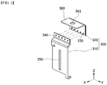
- FIG. 3 is an exploded perspective view of a first bus bar 300 included in the battery module 100 of FIG. 2 .
- the first bus bar 300 includes a first part 310 connected to the electrode lead 150 and a second part 320 connected to the connection member 500.
- a slit 350 may be formed in the first part 310 so that the electrode lead 150 can pass through. As mentioned above, the electrode lead 150 can be bent after passing through the lead slot and the slit 350 of the bus bar frame 210 together, and connected to the first portion 310.
- connection between the first part 310 and the electrode lead 150 is not particularly limited as long as electrical connection is possible, but may be mutually joined by welding.
- the second part 320 may include a connection part 360 that is joined to the connection member 500, and the connection part 360 may form a bent structure as shown in FIG. 3 for easily joining with the connection member 500.
- a module connection terminal 361 may be formed in the connection part 360.
- the module connection terminal 361 is configured to perform the role of a kind of nut and is responsible for a connection between adjacent battery modules. In a state in which the connection member 500 and the connection part 360 are in contact with each other, a bolt is fastened to the module connection terminal 361 so that the connection member 500 and the connection part 360 can be physically and electrically connected.
- a bolt is fastened to the module connection terminal 361 so that the connection member 500 and the connection part 360 can be physically and electrically connected.
- connection member 500 it is more preferable that the area excluding the portion where the bolt and the nut are fastened as described above is subjected to an insulating coating or covered with an insulator, thereby being electrically insulated from the outside.
- the second bus bar 400 of FIG. 2 can perform only the role of electrically connecting the electrode leads 150 extended from the battery cells 110, without being formed with such a connection part 360.
- the connecting member 500 in FIG. 2 is shown in a shape of plate, but the shape or material thereof is not limited as long as it can be connected to the connection part 360 of FIG. 3 to perform electrical connection between battery modules. That is, the connection member 500 may be in the shape of plate or in the shape of electric wire, and it goes without saying that other shapes that enables electrical connection are also possible.
- a protrusion part may be formed in any one of the first part 310 and the second part 320, and a through opening may be formed in the other one.
- FIG. 3 it is shown that the through opening 340 is formed in the first part 310 and the protrusion part 330 is formed in the second part 320, but this corresponds to one example.
- a protrusion part may be formed in the first part 310 and a through opening may be formed in the second part 320.
- a circular through opening 340 is shown, the shape is not limited as long as it is a shape of being perforated in the first part 310 or the second part 320, and thus a polygonal through opening is possible.
- the protrusion part 330 is inserted into the through opening 340 along the X-axis direction, so that the first part 310 and the second part 320 may be connected to each other.
- the protrusion part 330 may be disposed at a position corresponding to the through opening 340.
- the protrusion part 330 has a shape corresponding to the through opening 340.
- the protrusion part 330 is preferably a cylinder.
- the protrusion part 330 may be inserted into the through opening 340 to form a clinching joint.
- the area of the protrusion part 330 it is preferable that among the area of the protrusion part 330, the area of the plane perpendicular to the insertion direction of the protrusion part 330 is slightly larger than the area formed by the through opening 340.
- the circular area provided by the cylindrical protrusion part 330 is slightly larger than the circular area formed by the circular through opening 340.
- the inner wall of the through opening 340 and the protrusion part 330 form a structure in which the protrusion part 330 is in close contact with each other.
- the first part 310 and the second part 320 may be firmly fastened. This will be described again in FIG. 5 below.
- FIG. 4 is a perspective view showing a state in which the first part 310 and the second part 320 of the first bus bar 300 of FIG. 3 are fastened to each other. That is, this is a perspective view showing a state in which the protrusion part 330 of the second part 320 in FIG. 3 is inserted into the through opening 340 of the first part 310, so that the first part 310 and the second part 320 are fastened.
- the first bus bar 300 integrated as shown in FIG. 4 is connected to the connection member to electrically connect the battery modules.
- FIG. 5 is a cross-sectional view cut along the cutting line A-A' of FIG. 4 .
- this is a cross-sectional view in a normal operation state.
- the inner wall 341 of the through opening 340 and the protrusion part 330 may form a structure in which they are in close contact with each other.
- the first part 310 and the second part 320 can be firmly fastened, and in a normal operation state, the first bus bar 300 does not allow it to affect resistance, so that current between the battery modules can be smoothly transferred.
- each of the protrusion part 330 and the through opening 340 is not limited by the number thereof, but in order to firmly fasten the first part 310 and the second part 320, it is preferable that the number is two or more.
- the protrusion part 330 includes a material that shrinks in volume or changes its shape when the temperature rises. That is, when the battery module is placed in an abnormal operation state such as an overcurrent state or a high temperature state, the temperature of the protrusion part 330 rises, and the volume contracts or the shape changes.
- an abnormal operation state such as an overcurrent state or a high temperature state
- FIGS. 6 and 7 are cross-sectional views of the first bus bar of FIG. 5 in an abnormal operation state.
- FIG. 6 is a cross-sectional view of the first bus bar 300 having a protrusion part 330a that shrinks in volume as the temperature rises in an abnormal operation state
- FIG. 7 is a cross-sectional view of the first bus bar 300 having a protrusion part 330b that changes its shape as the temperature rises in an abnormal operation state.
- the temperature of the protrusion part 330a of the present embodiment rises, and when the temperature rises above a certain level, the volume may shrink.
- the protrusion part 330a may include a material that shrinks in volume as the temperature rises.
- the material that shrinks in volume may include a shape memory alloy. More specifically, the shape memory alloy may be welded to the second part 320 and then nickel plated to form the protrusion part 330a. In a normal operation state, it maintains electrical conductivity through nickel plating, and in the abnormal operation state, when the temperature rises above a certain level, the volume of the shape memory alloy decreases, so that the volume of the protrusion part 330a may decrease.
- the temperature at which the volume shrinkage of the shape memory alloy occurs is preferably 100 to 120 degrees Celsius in order to ensure safety against abnormal operation state.
- the protrusion part 330a is separated from the inner wall 341 of the through opening 340, so that the connection between the protrusion part 330a and the through opening 340 becomes loose. As a result, the connection force between the first part 310 and the second part 320 may be reduced, and thus separated from each other. Based on such a principle, the current flowing inside the battery module can be interrupted, thereby improving safety against abnormal operation state.
- the protrusion part 330b may include a material that changes its shape when the temperature rises.
- it may include a shape memory alloy that changes its shape as the temperature rises above a certain level.
- the shape memory alloy may be welded to the second part 320 and then nickel plated to form the protrusion part 330b. In a normal operation state, it maintains electrical conductivity through nickel plating, and in an abnormal operation state, when the temperature rises above a certain level as the temperature rises, the shape of the shape memory alloy may change and thus, the shape of the protrusion part 330b may change.
- the width of the protrusion part 330b in the direction parallel to the second part 320 may decrease, and the height in the direction perpendicular to the second part 320 (X-axis direction) may increase.
- a reduction in the width in a direction parallel to the second part 320 may be a reduction in the diameter of the cylinder
- an increase in the height in the direction perpendicular to the second part 320 may be an increase in the height of the cylinder.
- the protrusion part 330b is separated from the inner wall 341 of the through opening 340 so that the connection with the first part 310 becomes loose. As a result, the connection force between the first part 310 and the second part 320 is reduced, so that they are easily separated from each other.
- the protrusion part 330b has the effect of pushing the second part 320 from the first part 310, which may be more advantageous for current interruption.
- the volume of the protrusion part 330b is not limited, the volume of the protrusion part 330b can be reduced, increased or maintained in response to the reduction in width and increase in height as described above.
- the temperature at which the shape change of the shape memory alloy occurs is preferably 100 to 120 degrees Celsius in order to secure the safety against abnormal operation states.
- the battery module of the present disclosure may include a configuration of a module frame and an end plate that houses a battery cell stack or the like and protects it from the outside.
- One or more battery modules according to the present embodiment described above may be mounted together with various control and protection systems such as a battery management system (BMS) and a cooling system to form a battery pack.
- BMS battery management system
- a cooling system to form a battery pack.
- the battery module or the battery pack can be applied to various devices. These devices may be applied to transportation means such as an electric bicycle, an electric vehicle, a hybrid vehicle, but the present disclosure is not limited thereto and can be applied to various devices that can use the secondary battery.
Landscapes
- Chemical & Material Sciences (AREA)
- Chemical Kinetics & Catalysis (AREA)
- Electrochemistry (AREA)
- General Chemical & Material Sciences (AREA)
- Engineering & Computer Science (AREA)
- Aviation & Aerospace Engineering (AREA)
- Connection Of Batteries Or Terminals (AREA)
- Battery Mounting, Suspending (AREA)
Applications Claiming Priority (2)
| Application Number | Priority Date | Filing Date | Title |
|---|---|---|---|
| KR1020190103781A KR102860575B1 (ko) | 2019-08-23 | 2019-08-23 | 전지 모듈 및 이를 포함하는 전지 팩 |
| PCT/KR2020/009770 WO2021040242A1 (fr) | 2019-08-23 | 2020-07-24 | Module de batterie et bloc-batterie le comprenant |
Publications (2)
| Publication Number | Publication Date |
|---|---|
| EP4002577A1 true EP4002577A1 (fr) | 2022-05-25 |
| EP4002577A4 EP4002577A4 (fr) | 2024-10-16 |
Family
ID=74684511
Family Applications (1)
| Application Number | Title | Priority Date | Filing Date |
|---|---|---|---|
| EP20858909.3A Pending EP4002577A4 (fr) | 2019-08-23 | 2020-07-24 | Module de batterie et bloc-batterie le comprenant |
Country Status (6)
| Country | Link |
|---|---|
| US (1) | US12155091B2 (fr) |
| EP (1) | EP4002577A4 (fr) |
| JP (1) | JP7325890B2 (fr) |
| KR (1) | KR102860575B1 (fr) |
| CN (1) | CN114467217B (fr) |
| WO (1) | WO2021040242A1 (fr) |
Cited By (2)
| Publication number | Priority date | Publication date | Assignee | Title |
|---|---|---|---|---|
| WO2024023829A1 (fr) * | 2022-07-29 | 2024-02-01 | Tvs Motor Company Limited | Barres omnibus pour blocs-batteries |
| AT526985A2 (de) * | 2023-07-25 | 2024-07-15 | Avl List Gmbh | Formgedächtnislegierung zur Lenkung von Gas und Partikelströmen |
Families Citing this family (2)
| Publication number | Priority date | Publication date | Assignee | Title |
|---|---|---|---|---|
| CN118073787A (zh) * | 2022-11-24 | 2024-05-24 | 远景动力技术(江苏)有限公司 | 一种软包电芯、软包电芯的极耳折弯方法及电池包 |
| CN120882332A (zh) * | 2023-08-04 | 2025-10-31 | 韩国烟草人参公社 | 气溶胶生成装置 |
Family Cites Families (29)
| Publication number | Priority date | Publication date | Assignee | Title |
|---|---|---|---|---|
| JPS62202774U (fr) * | 1986-06-16 | 1987-12-24 | ||
| JP4494731B2 (ja) * | 2003-06-13 | 2010-06-30 | 三菱重工業株式会社 | 二次電池、二次電池の製造方法 |
| KR100861713B1 (ko) * | 2006-02-09 | 2008-10-06 | 주식회사 엘지화학 | 전지모듈 |
| JP5121188B2 (ja) | 2006-08-29 | 2013-01-16 | キヤノン株式会社 | 圧力制御弁、圧力制御弁の製造方法、及び圧力制御弁を搭載した燃料電池システム |
| KR20130033597A (ko) * | 2011-09-27 | 2013-04-04 | 에스케이이노베이션 주식회사 | 이차 전지 모듈 |
| JP2013073929A (ja) * | 2011-09-29 | 2013-04-22 | Gs Yuasa Corp | 電池パック |
| KR101724010B1 (ko) * | 2011-10-19 | 2017-04-07 | 삼성에스디아이 주식회사 | 이차 전지 |
| US8808031B2 (en) | 2011-12-14 | 2014-08-19 | Tyco Electronics Corporation | Battery connector system |
| KR20140125657A (ko) * | 2013-04-19 | 2014-10-29 | 삼성에스디아이 주식회사 | 이차전지 |
| KR101715695B1 (ko) * | 2013-09-05 | 2017-03-13 | 주식회사 엘지화학 | 배터리 팩 및 이에 적용되는 인터 버스 바 |
| KR101754609B1 (ko) | 2013-11-20 | 2017-07-06 | 삼성에스디아이 주식회사 | 퓨즈부를 갖는 이차 전지 |
| KR20160016363A (ko) | 2014-08-05 | 2016-02-15 | 주식회사 메가테크 | 배터리 모듈의 연결구조체 및 이를 구비한 배터리 모듈 |
| KR101679913B1 (ko) * | 2014-08-12 | 2016-11-25 | 현대자동차주식회사 | 배터리 모듈 |
| KR20160089133A (ko) | 2015-01-19 | 2016-07-27 | 삼성에스디아이 주식회사 | 배터리 모듈 |
| CN205376658U (zh) | 2016-02-29 | 2016-07-06 | 宁德时代新能源科技股份有限公司 | 二次电池 |
| KR102033001B1 (ko) | 2017-02-28 | 2019-10-16 | 주식회사 유라코퍼레이션 | 프레임 조립체, 프레임 조립체의 제조 방법 및 배터리 모듈의 제조 방법 |
| RS61814B1 (sr) | 2016-12-27 | 2021-06-30 | Yura Corporation Co Ltd | Fleksibilna strujna ploča i okvir koji uključuje istu |
| CN110114904B (zh) | 2016-12-27 | 2022-07-15 | 裕罗有限公司 | 汇流排组件及支架组件 |
| KR101928066B1 (ko) | 2016-12-29 | 2018-12-11 | 주식회사 유라코퍼레이션 | 버스바 어셈블리의 연결 구조 |
| KR20180091446A (ko) | 2017-02-07 | 2018-08-16 | 에이치엘그린파워 주식회사 | 배터리팩 및 이에 적용되는 버스바 |
| KR102316490B1 (ko) | 2017-03-22 | 2021-10-22 | 주식회사 엘지화학 | 콤팩트한 구조이면서도 전류 차단에 대한 신뢰성이 향상된 버스 바 어셈블리 및 이를 포함하는 전지모듈 |
| KR102249457B1 (ko) | 2017-05-16 | 2021-05-06 | 주식회사 엘지화학 | 배터리 모듈과 이를 포함하는 배터리 팩 및 자동차 |
| KR102267056B1 (ko) | 2017-06-20 | 2021-06-18 | 주식회사 엘지에너지솔루션 | 배터리 모듈과 이를 포함하는 배터리 팩 및 자동차 |
| KR102250180B1 (ko) | 2017-06-27 | 2021-05-07 | 주식회사 엘지화학 | 배터리 모듈과 이를 포함하는 배터리 팩 및 자동차 |
| CN111108576B (zh) | 2017-07-31 | 2023-03-07 | 24M技术公司 | 使用形状记忆材料的电流中断设备 |
| KR102259416B1 (ko) | 2017-12-14 | 2021-06-01 | 주식회사 엘지에너지솔루션 | 버스바 어셈블리를 포함하는 배터리 모듈 |
| KR102382386B1 (ko) | 2018-02-09 | 2022-04-01 | 주식회사 엘지에너지솔루션 | 전류 차단부를 구비한 버스바 및 그것을 포함한 배터리 모듈 |
| CN209087976U (zh) * | 2018-12-12 | 2019-07-09 | 东莞新能德科技有限公司 | 过流保护组件及电化学装置 |
| KR102722633B1 (ko) | 2019-03-26 | 2024-10-25 | 주식회사 엘지에너지솔루션 | 버스 바 모듈과 그 제조 방법 |
-
2019
- 2019-08-23 KR KR1020190103781A patent/KR102860575B1/ko active Active
-
2020
- 2020-07-24 JP JP2021576499A patent/JP7325890B2/ja active Active
- 2020-07-24 EP EP20858909.3A patent/EP4002577A4/fr active Pending
- 2020-07-24 WO PCT/KR2020/009770 patent/WO2021040242A1/fr not_active Ceased
- 2020-07-24 US US17/634,296 patent/US12155091B2/en active Active
- 2020-07-24 CN CN202080056245.XA patent/CN114467217B/zh active Active
Cited By (2)
| Publication number | Priority date | Publication date | Assignee | Title |
|---|---|---|---|---|
| WO2024023829A1 (fr) * | 2022-07-29 | 2024-02-01 | Tvs Motor Company Limited | Barres omnibus pour blocs-batteries |
| AT526985A2 (de) * | 2023-07-25 | 2024-07-15 | Avl List Gmbh | Formgedächtnislegierung zur Lenkung von Gas und Partikelströmen |
Also Published As
| Publication number | Publication date |
|---|---|
| JP2022537828A (ja) | 2022-08-30 |
| CN114467217A (zh) | 2022-05-10 |
| KR20210023506A (ko) | 2021-03-04 |
| JP7325890B2 (ja) | 2023-08-15 |
| US20220336926A1 (en) | 2022-10-20 |
| US12155091B2 (en) | 2024-11-26 |
| CN114467217B (zh) | 2024-03-01 |
| KR102860575B1 (ko) | 2025-09-15 |
| WO2021040242A1 (fr) | 2021-03-04 |
| EP4002577A4 (fr) | 2024-10-16 |
Similar Documents
| Publication | Publication Date | Title |
|---|---|---|
| US11177530B2 (en) | Battery pack | |
| CN109844996B (zh) | 电池模块和包括该电池模块的电池组和车辆 | |
| EP3166158B1 (fr) | Module de batterie rechargeable | |
| US10044019B2 (en) | Battery module having short-circuit connection member | |
| KR101683214B1 (ko) | 이차 전지 | |
| US12155091B2 (en) | Battery module and battery pack including the same | |
| US10998597B2 (en) | Battery module provided with connector breaking device | |
| EP3694016B1 (fr) | Bloc-batterie secondaire incluant un cadre de cellule avec une partie de prévention de revêtement | |
| JP6538274B2 (ja) | バッテリーモジュール及びこれを含むバッテリーパック | |
| EP4152503B1 (fr) | Bloc-batterie et véhicule le comprenant | |
| KR20140125657A (ko) | 이차전지 | |
| CN109075304B (zh) | 具有隔膜的可再充电电池 | |
| KR102917123B1 (ko) | 전지 모듈 및 이를 포함하는 전지팩 | |
| US12381288B2 (en) | Busbar module and method of manufacturing the same | |
| US20230231277A1 (en) | Battery pack | |
| WO2020012716A1 (fr) | Structure de connexion et module de batteries | |
| US12315964B2 (en) | Battery module and battery pack including the same | |
| US12512562B2 (en) | Battery pack and device including the same | |
| US20240387937A1 (en) | Battery device | |
| KR20220075045A (ko) | 배터리 모듈, 이를 포함하는 배터리 팩 및 자동차 |
Legal Events
| Date | Code | Title | Description |
|---|---|---|---|
| STAA | Information on the status of an ep patent application or granted ep patent |
Free format text: STATUS: THE INTERNATIONAL PUBLICATION HAS BEEN MADE |
|
| PUAI | Public reference made under article 153(3) epc to a published international application that has entered the european phase |
Free format text: ORIGINAL CODE: 0009012 |
|
| STAA | Information on the status of an ep patent application or granted ep patent |
Free format text: STATUS: REQUEST FOR EXAMINATION WAS MADE |
|
| 17P | Request for examination filed |
Effective date: 20220215 |
|
| AK | Designated contracting states |
Kind code of ref document: A1 Designated state(s): AL AT BE BG CH CY CZ DE DK EE ES FI FR GB GR HR HU IE IS IT LI LT LU LV MC MK MT NL NO PL PT RO RS SE SI SK SM TR |
|
| DAV | Request for validation of the european patent (deleted) | ||
| DAX | Request for extension of the european patent (deleted) | ||
| A4 | Supplementary search report drawn up and despatched |
Effective date: 20240916 |
|
| RIC1 | Information provided on ipc code assigned before grant |
Ipc: H01M 50/50 20210101ALI20240910BHEP Ipc: H01M 50/572 20210101AFI20240910BHEP |