EP4002626A1 - Position de commutation définie dans un parc éolien avant la panne d'alimentation dc - Google Patents
Position de commutation définie dans un parc éolien avant la panne d'alimentation dc Download PDFInfo
- Publication number
- EP4002626A1 EP4002626A1 EP20208744.1A EP20208744A EP4002626A1 EP 4002626 A1 EP4002626 A1 EP 4002626A1 EP 20208744 A EP20208744 A EP 20208744A EP 4002626 A1 EP4002626 A1 EP 4002626A1
- Authority
- EP
- European Patent Office
- Prior art keywords
- wind
- wind farm
- wind turbine
- network
- farm
- Prior art date
- Legal status (The legal status is an assumption and is not a legal conclusion. Google has not performed a legal analysis and makes no representation as to the accuracy of the status listed.)
- Pending
Links
Images


Classifications
-
- F—MECHANICAL ENGINEERING; LIGHTING; HEATING; WEAPONS; BLASTING
- F03—MACHINES OR ENGINES FOR LIQUIDS; WIND, SPRING, OR WEIGHT MOTORS; PRODUCING MECHANICAL POWER OR A REACTIVE PROPULSIVE THRUST, NOT OTHERWISE PROVIDED FOR
- F03D—WIND MOTORS
- F03D9/00—Adaptations of wind motors for special use; Combinations of wind motors with apparatus driven thereby; Wind motors specially adapted for installation in particular locations
- F03D9/10—Combinations of wind motors with apparatus storing energy
- F03D9/11—Combinations of wind motors with apparatus storing energy storing electrical energy
-
- H—ELECTRICITY
- H02—GENERATION; CONVERSION OR DISTRIBUTION OF ELECTRIC POWER
- H02J—ELECTRIC POWER NETWORKS; CIRCUIT ARRANGEMENTS OR SYSTEMS FOR SUPPLYING OR DISTRIBUTING ELECTRIC POWER; SYSTEMS FOR STORING ELECTRIC ENERGY
- H02J3/00—Circuit arrangements for AC mains or AC distribution networks
- H02J3/001—Arrangements for handling faults or abnormalities, e.g. emergencies or contingencies
-
- F—MECHANICAL ENGINEERING; LIGHTING; HEATING; WEAPONS; BLASTING
- F03—MACHINES OR ENGINES FOR LIQUIDS; WIND, SPRING, OR WEIGHT MOTORS; PRODUCING MECHANICAL POWER OR A REACTIVE PROPULSIVE THRUST, NOT OTHERWISE PROVIDED FOR
- F03D—WIND MOTORS
- F03D7/00—Controlling wind motors
- F03D7/02—Controlling wind motors the wind motors having rotation axis substantially parallel to the air flow entering the rotor
-
- F—MECHANICAL ENGINEERING; LIGHTING; HEATING; WEAPONS; BLASTING
- F03—MACHINES OR ENGINES FOR LIQUIDS; WIND, SPRING, OR WEIGHT MOTORS; PRODUCING MECHANICAL POWER OR A REACTIVE PROPULSIVE THRUST, NOT OTHERWISE PROVIDED FOR
- F03D—WIND MOTORS
- F03D7/00—Controlling wind motors
- F03D7/02—Controlling wind motors the wind motors having rotation axis substantially parallel to the air flow entering the rotor
- F03D7/028—Controlling wind motors the wind motors having rotation axis substantially parallel to the air flow entering the rotor controlling wind motor output power
- F03D7/0284—Controlling wind motors the wind motors having rotation axis substantially parallel to the air flow entering the rotor controlling wind motor output power in relation to the state of the electric grid
-
- F—MECHANICAL ENGINEERING; LIGHTING; HEATING; WEAPONS; BLASTING
- F03—MACHINES OR ENGINES FOR LIQUIDS; WIND, SPRING, OR WEIGHT MOTORS; PRODUCING MECHANICAL POWER OR A REACTIVE PROPULSIVE THRUST, NOT OTHERWISE PROVIDED FOR
- F03D—WIND MOTORS
- F03D7/00—Controlling wind motors
- F03D7/02—Controlling wind motors the wind motors having rotation axis substantially parallel to the air flow entering the rotor
- F03D7/04—Automatic control; Regulation
- F03D7/042—Automatic control; Regulation by means of an electrical or electronic controller
- F03D7/048—Automatic control; Regulation by means of an electrical or electronic controller controlling wind farms
-
- H—ELECTRICITY
- H02—GENERATION; CONVERSION OR DISTRIBUTION OF ELECTRIC POWER
- H02J—ELECTRIC POWER NETWORKS; CIRCUIT ARRANGEMENTS OR SYSTEMS FOR SUPPLYING OR DISTRIBUTING ELECTRIC POWER; SYSTEMS FOR STORING ELECTRIC ENERGY
- H02J13/00—Circuit arrangements for providing remote monitoring or remote control of equipment in a power distribution network
- H02J13/12—Monitoring network conditions, e.g. electrical magnitudes or operational status
-
- H—ELECTRICITY
- H02—GENERATION; CONVERSION OR DISTRIBUTION OF ELECTRIC POWER
- H02J—ELECTRIC POWER NETWORKS; CIRCUIT ARRANGEMENTS OR SYSTEMS FOR SUPPLYING OR DISTRIBUTING ELECTRIC POWER; SYSTEMS FOR STORING ELECTRIC ENERGY
- H02J13/00—Circuit arrangements for providing remote monitoring or remote control of equipment in a power distribution network
- H02J13/16—Circuit arrangements for providing remote monitoring or remote control of equipment in a power distribution network the power network being controlled at grid-level, e.g. using aggregators
-
- H—ELECTRICITY
- H02—GENERATION; CONVERSION OR DISTRIBUTION OF ELECTRIC POWER
- H02J—ELECTRIC POWER NETWORKS; CIRCUIT ARRANGEMENTS OR SYSTEMS FOR SUPPLYING OR DISTRIBUTING ELECTRIC POWER; SYSTEMS FOR STORING ELECTRIC ENERGY
- H02J3/00—Circuit arrangements for AC mains or AC distribution networks
- H02J3/001—Arrangements for handling faults or abnormalities, e.g. emergencies or contingencies
- H02J3/0012—Arrangements for handling faults or abnormalities, e.g. emergencies or contingencies characterised by the contingency detection means in AC networks, e.g. using phasor measurement units [PMU], synchrophasors or contingency analysis
-
- H—ELECTRICITY
- H02—GENERATION; CONVERSION OR DISTRIBUTION OF ELECTRIC POWER
- H02J—ELECTRIC POWER NETWORKS; CIRCUIT ARRANGEMENTS OR SYSTEMS FOR SUPPLYING OR DISTRIBUTING ELECTRIC POWER; SYSTEMS FOR STORING ELECTRIC ENERGY
- H02J3/00—Circuit arrangements for AC mains or AC distribution networks
- H02J3/38—Arrangements for feeding a single network from two or more generators or sources in parallel; Arrangements for feeding already energised networks from additional generators or sources in parallel
- H02J3/381—Dispersed generators
-
- H—ELECTRICITY
- H02—GENERATION; CONVERSION OR DISTRIBUTION OF ELECTRIC POWER
- H02J—ELECTRIC POWER NETWORKS; CIRCUIT ARRANGEMENTS OR SYSTEMS FOR SUPPLYING OR DISTRIBUTING ELECTRIC POWER; SYSTEMS FOR STORING ELECTRIC ENERGY
- H02J3/00—Circuit arrangements for AC mains or AC distribution networks
- H02J3/38—Arrangements for feeding a single network from two or more generators or sources in parallel; Arrangements for feeding already energised networks from additional generators or sources in parallel
- H02J3/40—Synchronisation of generators for connection to a network or to another generator
-
- F—MECHANICAL ENGINEERING; LIGHTING; HEATING; WEAPONS; BLASTING
- F05—INDEXING SCHEMES RELATING TO ENGINES OR PUMPS IN VARIOUS SUBCLASSES OF CLASSES F01-F04
- F05B—INDEXING SCHEME RELATING TO WIND, SPRING, WEIGHT, INERTIA OR LIKE MOTORS, TO MACHINES OR ENGINES FOR LIQUIDS COVERED BY SUBCLASSES F03B, F03D AND F03G
- F05B2270/00—Control
- F05B2270/30—Control parameters, e.g. input parameters
- F05B2270/337—Electrical grid status parameters, e.g. voltage, frequency or power demand
-
- H—ELECTRICITY
- H02—GENERATION; CONVERSION OR DISTRIBUTION OF ELECTRIC POWER
- H02J—ELECTRIC POWER NETWORKS; CIRCUIT ARRANGEMENTS OR SYSTEMS FOR SUPPLYING OR DISTRIBUTING ELECTRIC POWER; SYSTEMS FOR STORING ELECTRIC ENERGY
- H02J13/00—Circuit arrangements for providing remote monitoring or remote control of equipment in a power distribution network
- H02J13/14—Circuit arrangements for providing remote monitoring or remote control of equipment in a power distribution network the power network being locally controlled, e.g. home energy management systems [HEMS]
-
- H—ELECTRICITY
- H02—GENERATION; CONVERSION OR DISTRIBUTION OF ELECTRIC POWER
- H02J—ELECTRIC POWER NETWORKS; CIRCUIT ARRANGEMENTS OR SYSTEMS FOR SUPPLYING OR DISTRIBUTING ELECTRIC POWER; SYSTEMS FOR STORING ELECTRIC ENERGY
- H02J2101/00—Supply or distribution of decentralised, dispersed or local electric power generation
- H02J2101/20—Dispersed power generation using renewable energy sources
- H02J2101/28—Wind energy
-
- Y—GENERAL TAGGING OF NEW TECHNOLOGICAL DEVELOPMENTS; GENERAL TAGGING OF CROSS-SECTIONAL TECHNOLOGIES SPANNING OVER SEVERAL SECTIONS OF THE IPC; TECHNICAL SUBJECTS COVERED BY FORMER USPC CROSS-REFERENCE ART COLLECTIONS [XRACs] AND DIGESTS
- Y02—TECHNOLOGIES OR APPLICATIONS FOR MITIGATION OR ADAPTATION AGAINST CLIMATE CHANGE
- Y02E—REDUCTION OF GREENHOUSE GAS [GHG] EMISSIONS, RELATED TO ENERGY GENERATION, TRANSMISSION OR DISTRIBUTION
- Y02E10/00—Energy generation through renewable energy sources
- Y02E10/70—Wind energy
- Y02E10/76—Power conversion electric or electronic aspects
-
- Y—GENERAL TAGGING OF NEW TECHNOLOGICAL DEVELOPMENTS; GENERAL TAGGING OF CROSS-SECTIONAL TECHNOLOGIES SPANNING OVER SEVERAL SECTIONS OF THE IPC; TECHNICAL SUBJECTS COVERED BY FORMER USPC CROSS-REFERENCE ART COLLECTIONS [XRACs] AND DIGESTS
- Y02—TECHNOLOGIES OR APPLICATIONS FOR MITIGATION OR ADAPTATION AGAINST CLIMATE CHANGE
- Y02E—REDUCTION OF GREENHOUSE GAS [GHG] EMISSIONS, RELATED TO ENERGY GENERATION, TRANSMISSION OR DISTRIBUTION
- Y02E40/00—Technologies for an efficient electrical power generation, transmission or distribution
- Y02E40/70—Smart grids as climate change mitigation technology in the energy generation sector
-
- Y—GENERAL TAGGING OF NEW TECHNOLOGICAL DEVELOPMENTS; GENERAL TAGGING OF CROSS-SECTIONAL TECHNOLOGIES SPANNING OVER SEVERAL SECTIONS OF THE IPC; TECHNICAL SUBJECTS COVERED BY FORMER USPC CROSS-REFERENCE ART COLLECTIONS [XRACs] AND DIGESTS
- Y02—TECHNOLOGIES OR APPLICATIONS FOR MITIGATION OR ADAPTATION AGAINST CLIMATE CHANGE
- Y02E—REDUCTION OF GREENHOUSE GAS [GHG] EMISSIONS, RELATED TO ENERGY GENERATION, TRANSMISSION OR DISTRIBUTION
- Y02E70/00—Other energy conversion or management systems reducing GHG emissions
- Y02E70/30—Systems combining energy storage with energy generation of non-fossil origin
-
- Y—GENERAL TAGGING OF NEW TECHNOLOGICAL DEVELOPMENTS; GENERAL TAGGING OF CROSS-SECTIONAL TECHNOLOGIES SPANNING OVER SEVERAL SECTIONS OF THE IPC; TECHNICAL SUBJECTS COVERED BY FORMER USPC CROSS-REFERENCE ART COLLECTIONS [XRACs] AND DIGESTS
- Y04—INFORMATION OR COMMUNICATION TECHNOLOGIES HAVING AN IMPACT ON OTHER TECHNOLOGY AREAS
- Y04S—SYSTEMS INTEGRATING TECHNOLOGIES RELATED TO POWER NETWORK OPERATION, COMMUNICATION OR INFORMATION TECHNOLOGIES FOR IMPROVING THE ELECTRICAL POWER GENERATION, TRANSMISSION, DISTRIBUTION, MANAGEMENT OR USAGE, i.e. SMART GRIDS
- Y04S10/00—Systems supporting electrical power generation, transmission or distribution
- Y04S10/12—Monitoring or controlling equipment for energy generation units, e.g. distributed energy generation [DER] or load-side generation
- Y04S10/123—Monitoring or controlling equipment for energy generation units, e.g. distributed energy generation [DER] or load-side generation the energy generation units being or involving renewable energy sources
Definitions
- the present invention relates to a method for controlling a wind power plant and/or a wind farm and such a wind power plant and such a wind farm.
- a wind farm is usually connected to an electrical supply network via a grid connection point and has a large number of wind energy installations which are connected to one another via a shared electrical wind farm network.
- Such a wind farm can therefore also not participate in a network restoration of the electrical supply network.
- the object of the present invention is therefore to address one of the problems mentioned above.
- a possibility should be created, a method for a To provide a wind turbine or a wind farm with which it is possible to participate in a network restoration of an electrical supply network, especially if there was previously a persistent network failure.
- an alternative to what was previously known should be provided.
- a method for controlling a wind turbine or a wind farm comprising the steps of: determining a grid fault within an electrical supply grid operated by a grid operator, to which the wind turbine or the wind farm is electrically connected via a grid connection point; Switching of electrical switches of the wind turbine or the wind farm by a control unit of the wind turbine or the wind farm, which is operated by a low-voltage supply, so that the wind turbine or the wind farm is voltage-free; Checking an electrical storage device to ensure the low-voltage supply after the network fault has been detected within the electrical supply network; Switching further electrical switches of the wind turbine or the wind farm into a predefined switching state in which the wind turbine or the wind farm can be started up.
- a method is therefore proposed with which a wind farm is brought into a secure switch position, which enables the wind farm to be started up after a power failure.
- the method is preferably carried out by a wind energy installation control unit described below or a wind farm control unit described below.
- a first step of the method it is determined whether the electrical supply network has a network error, e.g. by means of a measuring unit of the wind turbine or a measuring unit of the wind farm, which is set up in particular to record a voltage of an electrical wind farm network and/or an electrical supply network .
- the network fault within the electrical supply network is preferably determined by detecting the network voltage of the electrical supply network.
- a network error is to be understood here as meaning in particular all those errors within an electrical supply network which, in particular for a short period of time, lead to a significant and/or lasting deviation in the network voltage from the nominal network voltage. According to this, there is a grid fault, for example, if the grid voltage drops from 100 percent of the nominal grid voltage to 90 percent of the nominal grid voltage within one second.
- a grid fault is understood to mean, in particular, a fault within the electrical supply grid in which the grid voltage is below 10 percent of the nominal grid voltage and the fault is present in particular for a longer period of time, for example for more than one minute.
- Such errors are also referred to as serious network errors and generally lead to network failure.
- a grid fault is to be understood in particular as a grid failure in which the electrical supply grid essentially no longer has any voltage, preferably for at least 30 minutes.
- At least one electrical switch of the wind power plant or wind farm is switched, preferably by a control unit of the wind power plant or wind farm, so that the wind power plant or wind farm is de-energized.
- a control unit of the wind power plant or wind farm preferably by a control unit of the wind power plant or wind farm.
- the wind energy plant is disconnected from the electrical wind farm network by means of a circuit breaker or that the wind farm is disconnected from the electrical supply network by means of a circuit breaker.
- the switching takes place in particular in such a way that a power train of the wind energy installation or of the wind farm is disconnected from the power supply.
- Voltage-free or voltage-free is to be understood here in particular as meaning that the power train of the wind energy installation or of the wind farm essentially no longer has any voltage. Nevertheless, the control and management system strand, which includes the communication, control and protection devices, for example, can still have an operating voltage, in particular to ensure the operational safety of the wind energy installation or the wind farm.
- a power train usually has several hundred volts, preferably more than 1 kV, and is used in particular to transport power.
- a control and instrumentation line usually has 12V or 24V or a few hundred volts, depending on the equipment, and is used in particular for the exchange of information and data.
- a further step it is checked whether the electrical storage device of the wind turbine or wind farm, which is used to ensure the low-voltage supply, i.e. the control and instrumentation system, still has sufficient electrical energy, in particular to activate and execute an incident control and/or or to restart the wind turbine or the wind farm at a later point in time.
- the electrical storage device of the wind turbine or wind farm which is used to ensure the low-voltage supply, i.e. the control and instrumentation system, still has sufficient electrical energy, in particular to activate and execute an incident control and/or or to restart the wind turbine or the wind farm at a later point in time.
- the state of charge of the electrical storage device of the control and instrumentation line is therefore checked, for example by the wind turbine control unit or the wind farm control unit.
- This is intended in particular to prevent the electrical storage device from being completely discharged while the wind turbine or the wind farm is disconnected from the electrical supply network and, in particular, is not generating any electrical power.
- the wind turbine or the wind farm can no longer be controlled from outside, for example by a grid operator.
- remote control of the wind energy installation or of the wind farm would then no longer be possible.
- the further switches are switched to a predefined switching state, preferably in such a way that the wind energy installation or the wind farm can be started up again at a later point in time
- the predefined switching states are stored in the wind turbine control unit or the wind farm control unit, ie preferably as a function of a state of charge of the electrical storage device.
- a standby mode for wind turbines or wind parks is therefore preferably proposed, which is assumed by predefined switch positions, in particular by circuit breakers.
- An example of this is: a wind farm with ten wind turbines, which is disconnected from the electricity grid after a grid failure, with eight of the ten wind turbines also being disconnected from the wind farm electricity grid, so that only two of the wind farm's ten wind turbines are still connected to the wind farm electricity grid. These two wind turbines are then used to restart the wind farm at a later point in time.
- Such a procedure makes it possible, in particular, to start up a wind farm by remote control, even if it hardly has any energy left to start up.
- Such a wind farm can then, in particular, take part in grid restoration.
- the network fault is preferably an, in particular permanent, failure of the electrical supply network.
- the network error is therefore in particular a network failure or a so-called black out and the method described above or below is used in particular to reestablish an electrical supply network with a wind turbine or a wind farm.
- LVRT low voltage ride through
- the predefined switching state is preferably specified by a network operator of the electrical supply network.
- the switching state is therefore in particular predefined or selected in such a way that the requirements of a network operator are satisfied.
- the grid operator prescribes certain requirements for the grid connection point in the event of a grid failure or grid restoration, which must be met using the predefined switching state.
- Such requirements can, for example, be specified by the network operator through a network protection concept.
- the low voltage is supplied with electrical energy for internal use, in particular in such a way that any communication, control and protection devices of the wind turbine or wind farm are supplied with electricity or kept ready for operation.
- the decoupling device is designed in particular as a circuit breaker and is set up to disconnect the wind energy installation or the wind farm from an electrical wind farm network or an electrical supply network.
- the switching of the further electrical switches of the wind energy installation or of the wind farm into a predefined switching state preferably takes place only after a grid operator has been informed that the further electrical switches are to be switched.
- the wind energy installation or wind farm assumes the predefined switching state only in agreement with the grid operator.
- the wind energy installation or the wind farm therefore preferably reports to a grid operator that the predefined switching state is to be adopted, and the grid operator confirms this.
- the detected or ascertained network error be verified by the network operator of the electrical supply network.
- the wind turbine or the wind farm detects a grid error, in particular a grid failure, this is verified by the grid operator, for example by means of a signal line between the wind turbine control unit or the wind farm control unit and the grid operator.
- the grid operator then verifies the wind energy installation or the wind farm that the grid fault identified is a fault or, for example, a deliberate grid shutdown, which in particular is not a grid fault.
- the method also includes the step: sending status information to a network operator of the electrical supply network that the other switches of the wind energy installation or of the wind farm have been switched.
- the wind farm can assume that the network error has been verified.
- the incident control reported back to the grid operator can signal that the defined switch position has also been switched on.
- the method also includes the step: activating an incident control of the wind power plant or the wind farm, in which a safe operation of the wind power plant or wind farm is made possible despite the network error.
- the method further includes the step: galvanic isolation of the wind power plant or the wind farm from the electrical supply network by means of a decoupling device, in particular in order to switch off the wind power plant or the wind farm.
- the galvanic separation can take place, for example, by means of a decoupling device in the form of a circuit breaker in the form of a coupling switch, which is preferably arranged in the, in particular electrical, proximity of a transformer, for example a wind farm transformer.
- a wind energy plant with a low-voltage supply which has an electrical storage device and a wind energy plant control unit, which is set up to carry out a method described above or below.
- the wind energy installation is preferably designed as described above or below.
- the wind power plant includes at least one wind power plant control unit described above or below, which is operated via a low-voltage power supply.
- the wind energy plant therefore has at least one low voltage of, for example, less than 1 kV, by means of which any communication, control and protection devices of the wind energy plant are supplied.
- the wind energy plant is a wind energy plant of a wind farm described above or below
- the wind energy plant control unit is preferably set up to communicate with a wind farm control unit described above or below, for example via a signal line.
- the wind turbine control unit has a measuring unit described above or below, which is set up to detect a voltage of an electrical wind farm grid and/or an electrical supply grid.
- a wind farm with a low-voltage supply which has an electrical storage device and a wind farm control unit, which is set up to carry out a method described above or below.
- the wind farm is preferably connected to an electrical supply network via a grid connection point and has a large number of wind energy installations which are connected to one another via a shared electrical wind farm network.
- the wind farm preferably comprises a multiplicity of wind energy installations, as described above or below.
- the wind farm is particularly preferably controlled by means of a wind farm control unit described above or below.
- the wind farm includes at least one wind turbine control unit described above or below, which is operated via a low-voltage power supply.
- the wind farm therefore has at least one low voltage of, for example, less than 1 kV, by means of which any communication, control and protection devices of the wind farm are supplied.
- the low voltages of the individual wind energy installations of the wind farm are preferably also connected to this low voltage.
- the wind farm control unit has a measuring unit described above or below, which is set up to detect a voltage of an electrical wind farm grid and/or an electrical supply grid.
- the electrical storage device described here has the particular task of acting as an uninterruptible power supply (UPS for short) that supplies any communication, control and protection devices of the wind turbine or wind farm with electricity even when the wind turbine or wind farm has no electrical power generated because, for example, the electrical supply network has failed.
- UPS uninterruptible power supply
- FIG. 1 10 shows a schematic view of a wind turbine 100 according to an embodiment.
- the wind energy installation 100 has a tower 102 and a nacelle 104 .
- An aerodynamic rotor 106 with three rotor blades 108 and a spinner 110 is arranged on the nacelle 104 .
- the rotor 106 is rotated by the wind and thereby drives a generator in the nacelle 104 .
- the wind energy installation 100 has a wind energy installation control unit described above or below, which is connected to a wind farm control unit and/or a network operator, in particular described above or below.
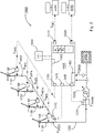
- FIG. 2 shows a schematic structure of a wind farm 1000 according to an embodiment.
- the wind farm 1000 includes a variety of wind turbines 1100, such as 1 shown, which are connected to one another via a common wind farm network 1200 .
- the wind farm network 1200 has switches 1210, in particular a coupling switch for the wind farm, and further switches 1220 and is connected to an electrical supply network 2000 by means of a wind farm transformer 1300 in order, for example, to feed in an electrical wind farm power P park , which is the sum of the individual electrical Wind turbine power P wea composed.
- the wind energy plant 1100 and the wind farm grid 1200 together with the wind farm transformer form the power train (continuous lines), ie in particular those assemblies which are responsible for transporting energy into the electrical supply grid.
- the wind farm 1000 has a wind farm control unit 1400 which is set up to control the wind farm 1000 .
- the wind farm control unit 1400 is connected in particular to the wind power plant control units 1180 of the wind power plants 1100 .
- the wind farm 1000 therefore has, in addition to the power line (continuous lines), also a control and guidance system line (dashed lines), which is described below.
- the wind farm control unit 1400 has a large number of interfaces 1410, 1420, 1430, 1440, 1450, 1460 and a large number of operating modes B1, B2, B3, such as an incident control, and is supplied with energy by means of an electrical storage device, in particular also then , if the wind farm does not generate any electrical power and/or the electrical supply network has a network fault or has failed.
- the interface 1410 is set up to send signals to a network operator 3000 or to receive them.
- This interface 1410 can also be referred to as a network operator interface.
- the interface 1420 is, for example, an interface for the plant operator 4000, who can also access the wind farm via this interface 1420.
- This interface 1420 can also be referred to as a wind farm operator interface 1420 .
- the individual wind energy installations 1100 of the wind farm 1000 are controlled via a control interface 1430 which is connected to the individual wind energy installation control units 1180, for example by means of various control signals S NIS .
- the wind farm control unit can use the interface 1440 to disconnect the wind farm from the electrical supply network using the switch 1210 .
- This interface 1440 can also be referred to as a separation interface.
- the wind farm control unit can use the interface 1450 to record the feed-in of the wind farm and/or a voltage U grid in the electrical supply network 2000 .
- This interface 1450 can also be referred to as a measurement interface.
- the wind farm control unit can monitor the state of the electrical storage device 1500 by means of the interface 1460 .
- This interface 1460 can also be referred to as a monitoring interface.
- the wind farm control unit can switch a further switch 1220 by means of the interface 1470, in particular in such a way that the wind farm has a predefined switching state.
- This interface can also be referred to as a switching interface.
- FIG. 5 shows a schematic sequence 5000 of a method for controlling a wind farm according to an embodiment.
- a network error is detected, e.g. via a measurement interface of a wind farm control unit, as in 2 shown.
- a next step 5200 the network error is verified with a network operator, e.g. via a network operator interface, as in 2 shown.
- a network error can also be assumed after a certain period of time.
- a next step 5300 the wind farm is disconnected from the electrical supply network, e.g. via a disconnection interface using a switch, as in 2 shown.
- a next step 5400 the electrical storage device is checked, e.g. via a monitoring interface, as in 2 shown, and switched another switch, so that the wind farm has a predefined switching state, in particular so that a network protection plan of a network operator is met.
Landscapes
- Engineering & Computer Science (AREA)
- Power Engineering (AREA)
- Life Sciences & Earth Sciences (AREA)
- Sustainable Development (AREA)
- Sustainable Energy (AREA)
- Chemical & Material Sciences (AREA)
- Combustion & Propulsion (AREA)
- Mechanical Engineering (AREA)
- General Engineering & Computer Science (AREA)
- Supply And Distribution Of Alternating Current (AREA)
- Wind Motors (AREA)
Priority Applications (3)
| Application Number | Priority Date | Filing Date | Title |
|---|---|---|---|
| EP20208744.1A EP4002626A1 (fr) | 2020-11-19 | 2020-11-19 | Position de commutation définie dans un parc éolien avant la panne d'alimentation dc |
| US17/530,054 US11619207B2 (en) | 2020-11-19 | 2021-11-18 | Defined switch position in a wind farm prior to failure of the DC power supply |
| CN202111375564.XA CN114542382A (zh) | 2020-11-19 | 2021-11-19 | 用于控制风能设施或风电场的方法和风能设施或风电场 |
Applications Claiming Priority (1)
| Application Number | Priority Date | Filing Date | Title |
|---|---|---|---|
| EP20208744.1A EP4002626A1 (fr) | 2020-11-19 | 2020-11-19 | Position de commutation définie dans un parc éolien avant la panne d'alimentation dc |
Publications (1)
| Publication Number | Publication Date |
|---|---|
| EP4002626A1 true EP4002626A1 (fr) | 2022-05-25 |
Family
ID=73497682
Family Applications (1)
| Application Number | Title | Priority Date | Filing Date |
|---|---|---|---|
| EP20208744.1A Pending EP4002626A1 (fr) | 2020-11-19 | 2020-11-19 | Position de commutation définie dans un parc éolien avant la panne d'alimentation dc |
Country Status (3)
| Country | Link |
|---|---|
| US (1) | US11619207B2 (fr) |
| EP (1) | EP4002626A1 (fr) |
| CN (1) | CN114542382A (fr) |
Citations (4)
| Publication number | Priority date | Publication date | Assignee | Title |
|---|---|---|---|---|
| EP1993184A1 (fr) * | 2007-05-14 | 2008-11-19 | Siemens Aktiengesellschaft | Procédé de démarrage d'au moins une partie d'une installation éolienne, installation éolienne et utilisation de l'installation éolienne |
| WO2011058170A1 (fr) * | 2009-11-16 | 2011-05-19 | Vestas Wind Systems A/S | Procédé et dispositif permettant de faire fonctionner une centrale éolienne |
| WO2016115662A1 (fr) * | 2015-01-19 | 2016-07-28 | Abb Technology Ltd | Procédé d'exploitation d'un parc éolien en mode d'îlotage et système de commande associé |
| DE102018125445A1 (de) * | 2018-10-15 | 2020-04-16 | Wobben Properties Gmbh | Störfallregelung für einen Windpark |
Family Cites Families (6)
| Publication number | Priority date | Publication date | Assignee | Title |
|---|---|---|---|---|
| EP2270331B1 (fr) * | 2009-06-30 | 2020-03-04 | Vestas Wind Systems A/S | Eolienne comprenant un dispositif de contrôle de puissance pendant une panne du réseau |
| DE102010056457A1 (de) * | 2010-12-29 | 2012-07-05 | Repower Systems Ag | Windpark und Verfahren zum Betreiben eines Windparks |
| CN202749836U (zh) * | 2012-07-11 | 2013-02-20 | 华锐风电科技(集团)股份有限公司 | 一种双馈风力发电系统的低压穿越装置 |
| CN104836257A (zh) * | 2015-06-02 | 2015-08-12 | 中国农业大学 | 一种风力发电低电压穿越综合调控装置 |
| DE102016123384A1 (de) * | 2016-12-02 | 2018-06-07 | Wobben Properties Gmbh | Verfahren zum Wiederaufbau eines elektrischen Versorgungsnetzes |
| EP3651304B1 (fr) * | 2018-11-07 | 2021-04-07 | Siemens Gamesa Renewable Energy Innovation & Technology, S.L. | Procédé de réalisation d'une procédure de test d'un système d'alimentation électrique pour éolienne et système d'alimentation électrique |
-
2020
- 2020-11-19 EP EP20208744.1A patent/EP4002626A1/fr active Pending
-
2021
- 2021-11-18 US US17/530,054 patent/US11619207B2/en active Active
- 2021-11-19 CN CN202111375564.XA patent/CN114542382A/zh not_active Withdrawn
Patent Citations (5)
| Publication number | Priority date | Publication date | Assignee | Title |
|---|---|---|---|---|
| EP1993184A1 (fr) * | 2007-05-14 | 2008-11-19 | Siemens Aktiengesellschaft | Procédé de démarrage d'au moins une partie d'une installation éolienne, installation éolienne et utilisation de l'installation éolienne |
| EP1993184B1 (fr) * | 2007-05-14 | 2018-03-14 | Siemens Aktiengesellschaft | Procédé de démarrage d'au moins une partie d'une installation éolienne, installation éolienne et utilisation de l'installation éolienne |
| WO2011058170A1 (fr) * | 2009-11-16 | 2011-05-19 | Vestas Wind Systems A/S | Procédé et dispositif permettant de faire fonctionner une centrale éolienne |
| WO2016115662A1 (fr) * | 2015-01-19 | 2016-07-28 | Abb Technology Ltd | Procédé d'exploitation d'un parc éolien en mode d'îlotage et système de commande associé |
| DE102018125445A1 (de) * | 2018-10-15 | 2020-04-16 | Wobben Properties Gmbh | Störfallregelung für einen Windpark |
Also Published As
| Publication number | Publication date |
|---|---|
| US20220154692A1 (en) | 2022-05-19 |
| CN114542382A (zh) | 2022-05-27 |
| US11619207B2 (en) | 2023-04-04 |
Similar Documents
| Publication | Publication Date | Title |
|---|---|---|
| EP2044325B2 (fr) | Procédé permettant de faire fonctionner une éolienne | |
| DE202019100531U1 (de) | Umfassendes Überwachungs- und Steuerungssystem für Lithium-Ionen-Batterien | |
| DE102010056458A1 (de) | Windpark und Verfahren zum Betreiben eines Windparks | |
| WO2010124886A2 (fr) | Procédé permettant de faire fonctionner un dispositif de réglage du calage de pales de rotor | |
| DE102005038558A1 (de) | Verfahren zum Betrieb eines Windenergieanlagenparks sowie Windenergieanlagenpark | |
| WO2018100125A1 (fr) | Procédé de rétablissement d'un réseau d'alimentation électrique | |
| WO2017121697A1 (fr) | Éolienne | |
| EP2636894B1 (fr) | Système d'éolienne offshore | |
| EP3336998A1 (fr) | Installation auxiliaire d'alimentation, convertisseur pour une installation auxiliaire d'alimentation ainsi que procédé de fonctionnement d'une installation auxiliaire d'alimentation | |
| EP3711133A1 (fr) | Procédé de démarrage autonome d'un dispositif d'alimentation en énergie, onduleur bidirectionnel et dispositif d'alimentation en énergie doté d'un onduleur bidirectionnel | |
| WO2019011846A1 (fr) | Dispositif et procédé de contrôle du comportement électrodynamique d'une chaîne cinématique d'un dispositif de génération d'énergie sur le réseau | |
| EP3850721A1 (fr) | Parc éolien doté d'une unité de flux de puissance et unité de flux de puissance de ce type | |
| EP2936646B1 (fr) | Système et procédé pour séparer une alimentation électrique locale d'un réseau électrique | |
| WO2014173685A1 (fr) | Parc éolien et procédé de commande d'un parc éolien | |
| DE102018125445A1 (de) | Störfallregelung für einen Windpark | |
| EP3555987B1 (fr) | Procédé de gestion du rétablissement d'un réseau | |
| DE202010004045U1 (de) | Windkraftanlage | |
| DE102011084688B4 (de) | Batteriesystem | |
| EP4104269A1 (fr) | Alimentation électrique redondante, en particulier destinée à un centre de données, et procédé et programme informatique correspondants | |
| AT524421B1 (de) | Verfahren zur zeitstaffelungsschutzkompatiblen selektiven netzkurzschlusserkennenden Überwachung des Betriebes eines elektrischen Energienetzes | |
| EP4572059A1 (fr) | Procédé de commande d'un réseau d'alimentation électrique et système d'alimentation électrique | |
| WO2012163731A2 (fr) | Procédé de fonctionnement d'un générateur dans un réseau électrique et réseau électrique comprenant un générateur de ce type | |
| US11619207B2 (en) | Defined switch position in a wind farm prior to failure of the DC power supply | |
| DE102022101459A1 (de) | System zur hochverfügbaren Hilfsenergieversorgung sowie dazugehöriges Verfahren | |
| EP4307509A1 (fr) | Procédé et système de détection de défaillances d'un transformateur de réseau local pouvant être régulé |
Legal Events
| Date | Code | Title | Description |
|---|---|---|---|
| PUAI | Public reference made under article 153(3) epc to a published international application that has entered the european phase |
Free format text: ORIGINAL CODE: 0009012 |
|
| STAA | Information on the status of an ep patent application or granted ep patent |
Free format text: STATUS: THE APPLICATION HAS BEEN PUBLISHED |
|
| AK | Designated contracting states |
Kind code of ref document: A1 Designated state(s): AL AT BE BG CH CY CZ DE DK EE ES FI FR GB GR HR HU IE IS IT LI LT LU LV MC MK MT NL NO PL PT RO RS SE SI SK SM TR |
|
| STAA | Information on the status of an ep patent application or granted ep patent |
Free format text: STATUS: REQUEST FOR EXAMINATION WAS MADE |
|
| 17P | Request for examination filed |
Effective date: 20221125 |
|
| RBV | Designated contracting states (corrected) |
Designated state(s): AL AT BE BG CH CY CZ DE DK EE ES FI FR GB GR HR HU IE IS IT LI LT LU LV MC MK MT NL NO PL PT RO RS SE SI SK SM TR |
|
| STAA | Information on the status of an ep patent application or granted ep patent |
Free format text: STATUS: EXAMINATION IS IN PROGRESS |
|
| 17Q | First examination report despatched |
Effective date: 20250624 |