EP4002630A2 - Système et procédé de fonctionnement d'un système de distribution d'énergie - Google Patents
Système et procédé de fonctionnement d'un système de distribution d'énergie Download PDFInfo
- Publication number
- EP4002630A2 EP4002630A2 EP21207569.1A EP21207569A EP4002630A2 EP 4002630 A2 EP4002630 A2 EP 4002630A2 EP 21207569 A EP21207569 A EP 21207569A EP 4002630 A2 EP4002630 A2 EP 4002630A2
- Authority
- EP
- European Patent Office
- Prior art keywords
- power
- power distribution
- primary
- distribution system
- subset
- Prior art date
- Legal status (The legal status is an assumption and is not a legal conclusion. Google has not performed a legal analysis and makes no representation as to the accuracy of the status listed.)
- Granted
Links
Images


Classifications
-
- H—ELECTRICITY
- H02—GENERATION; CONVERSION OR DISTRIBUTION OF ELECTRIC POWER
- H02J—ELECTRIC POWER NETWORKS; CIRCUIT ARRANGEMENTS OR SYSTEMS FOR SUPPLYING OR DISTRIBUTING ELECTRIC POWER; SYSTEMS FOR STORING ELECTRIC ENERGY
- H02J4/00—Circuit arrangements for mains or distribution networks not specified as AC or DC; Circuit arrangements for mains or distribution networks combining AC and DC sections or sub-networks
-
- B—PERFORMING OPERATIONS; TRANSPORTING
- B64—AIRCRAFT; AVIATION; COSMONAUTICS
- B64D—EQUIPMENT FOR FITTING IN OR TO AIRCRAFT; FLIGHT SUITS; PARACHUTES; ARRANGEMENT OR MOUNTING OF POWER PLANTS OR PROPULSION TRANSMISSIONS IN AIRCRAFT
- B64D41/00—Power installations for auxiliary purposes
-
- H—ELECTRICITY
- H02—GENERATION; CONVERSION OR DISTRIBUTION OF ELECTRIC POWER
- H02J—ELECTRIC POWER NETWORKS; CIRCUIT ARRANGEMENTS OR SYSTEMS FOR SUPPLYING OR DISTRIBUTING ELECTRIC POWER; SYSTEMS FOR STORING ELECTRIC ENERGY
- H02J3/00—Circuit arrangements for AC mains or AC distribution networks
-
- H—ELECTRICITY
- H02—GENERATION; CONVERSION OR DISTRIBUTION OF ELECTRIC POWER
- H02J—ELECTRIC POWER NETWORKS; CIRCUIT ARRANGEMENTS OR SYSTEMS FOR SUPPLYING OR DISTRIBUTING ELECTRIC POWER; SYSTEMS FOR STORING ELECTRIC ENERGY
- H02J13/00—Circuit arrangements for providing remote monitoring or remote control of equipment in a power distribution network
- H02J13/18—Circuit arrangements for providing remote monitoring or remote control of equipment in a power distribution network characterised by the remotely-controlled equipment, e.g. converters or transformers
- H02J13/34—Circuit arrangements for providing remote monitoring or remote control of equipment in a power distribution network characterised by the remotely-controlled equipment, e.g. converters or transformers the equipment being switches, relays or circuit breakers
-
- H—ELECTRICITY
- H02—GENERATION; CONVERSION OR DISTRIBUTION OF ELECTRIC POWER
- H02J—ELECTRIC POWER NETWORKS; CIRCUIT ARRANGEMENTS OR SYSTEMS FOR SUPPLYING OR DISTRIBUTING ELECTRIC POWER; SYSTEMS FOR STORING ELECTRIC ENERGY
- H02J3/00—Circuit arrangements for AC mains or AC distribution networks
- H02J3/12—Arrangements for adjusting voltage in AC networks by changing a characteristic of the network load
- H02J3/14—Arrangements for adjusting voltage in AC networks by changing a characteristic of the network load by switching loads on to, or off from, the networks, e.g. progressively balanced loading
-
- B—PERFORMING OPERATIONS; TRANSPORTING
- B64—AIRCRAFT; AVIATION; COSMONAUTICS
- B64D—EQUIPMENT FOR FITTING IN OR TO AIRCRAFT; FLIGHT SUITS; PARACHUTES; ARRANGEMENT OR MOUNTING OF POWER PLANTS OR PROPULSION TRANSMISSIONS IN AIRCRAFT
- B64D2221/00—Electric power distribution systems onboard aircraft
-
- H—ELECTRICITY
- H02—GENERATION; CONVERSION OR DISTRIBUTION OF ELECTRIC POWER
- H02J—ELECTRIC POWER NETWORKS; CIRCUIT ARRANGEMENTS OR SYSTEMS FOR SUPPLYING OR DISTRIBUTING ELECTRIC POWER; SYSTEMS FOR STORING ELECTRIC ENERGY
- H02J2105/00—Networks for supplying or distributing electric power characterised by their spatial reach or by the load
- H02J2105/30—Networks for supplying or distributing electric power characterised by their spatial reach or by the load the load networks being external to vehicles, i.e. exchanging power with vehicles
- H02J2105/32—Networks for supplying or distributing electric power characterised by their spatial reach or by the load the load networks being external to vehicles, i.e. exchanging power with vehicles for aircrafts
-
- H—ELECTRICITY
- H02—GENERATION; CONVERSION OR DISTRIBUTION OF ELECTRIC POWER
- H02J—ELECTRIC POWER NETWORKS; CIRCUIT ARRANGEMENTS OR SYSTEMS FOR SUPPLYING OR DISTRIBUTING ELECTRIC POWER; SYSTEMS FOR STORING ELECTRIC ENERGY
- H02J2105/00—Networks for supplying or distributing electric power characterised by their spatial reach or by the load
- H02J2105/50—Networks for supplying or distributing electric power characterised by their spatial reach or by the load for selectively controlling the operation of the loads
- H02J2105/52—Networks for supplying or distributing electric power characterised by their spatial reach or by the load for selectively controlling the operation of the loads for limitation of the power consumption in the networks or in one section of the networks, e.g. load shedding or peak shaving
Definitions
- the disclosure relates to a method and system for operating a power distribution system.
- Power distribution nodes can, for instance, further provide switching operations to selectively enable or disable the delivery of power to particular electrical loads, depending on, for example, available power distribution supply, criticality of electrical load functionality, or aircraft mode of operation, such as take-off, cruise, or ground operations.
- the disclosure relates to a power distribution system, including a primary power distribution node defining a set of primary distribution switches, each having an output and operable in a first conducting mode and a second non-conducting mode, and wherein operating in the second non-conducting mode includes a leakage current through the power distribution switch, and including a primary power distribution node power source configured to receive a first power, and supply a second power to an output, the second power less than the first power, and a controller module associated with the primary power distribution node and configured to identify a subset of electrical loads desired to be energized during an idle state of the power distribution system, defining a set of enabled electrical loads, identify a subset of secondary power distribution nodes not associated with any of the set of enabled electrical loads, switchably disconnect the subset of secondary power distribution nodes from a limited power supply, by way of opening a subset of the primary distribution switches positioned in a primary power distribution node upstream of the respective subset of secondary power distribution nodes, and supply the second power to
- the disclosure relates to a method of reducing leakage current in a power distribution system, including identifying a subset of electrical loads desired to be energized during an idle state of the power distribution system, defining a set of enabled electrical loads, identifying a subset of secondary power distribution nodes not associated with any of the set of enabled electrical loads, switchably disconnecting the subset of secondary power distribution nodes from a limited power supply, by way of opening a primary distribution switch positioned in a primary power distribution node upstream of the subset of secondary power distribution nodes, and supplying a low voltage power supply to the output of the opened primary power distribution switch, wherein the low voltage power supply reduces leakage current across the primary distribution switch.
- the disclosure relates to a power distribution system, including a primary power distribution node defining a set of primary distribution switches, each having an output and operable in a first conducting mode and a second non-conducting mode, and wherein operating in the second non-conducting mode includes a leakage current through the power distribution switch, and including a primary power distribution node power source configured to receive a first power, and supply a second power to an output, the second power less than the first power, a first secondary power distribution node including at least one enabled electrical load operable in a low power consumption mode of the power distribution system, the first secondary power distribution node connectable to the primary power distribution node by a first primary distribution switch, and a second secondary power distribution node not associated without any enabled electrical loads operable in the low power consumption mode of the power distribution system, the second secondary power distribution node connectable to the primary power distribution node by a second primary distribution switch.
- the second secondary power distribution node In response to the power distribution system operating in the low power consumption mode, the second secondary power distribution node is selectively disconnected from a power distribution system power source, and wherein the primary power distribution node power source supplies the second power to the second secondary power distribution node to operably reduce the leakage current through the second primary distribution switch.
- aspects of the present disclosure are described herein in the context of a power source in an aircraft, which enables production of electrical power from an energy source such as a turbine engine, jet fuel, hydrogen, batteries, etc.
- an energy source such as a turbine engine, jet fuel, hydrogen, batteries, etc.
- applicable mobile environments can include an aircraft, spacecraft, space-launch vehicle, satellite, locomotive, automobile, etc.
- Commercial environments can include manufacturing facilities or power generation and distribution facilities or infrastructure.
- a “limited power source” can include any power source that is limited in supplying an amount or quantity of power over a period of time by way of, for example, a discharge cycle of operation.
- Limited power sources can include, but are not limited to, fuel cell systems, hydrogen cell systems, capacitors, super capacitors, battery systems, rechargeable systems, banks of any of the preceding examples, or combinations thereof.
- a limited power source can include a power source that can be depleted, yet inconvenient or impractical to recharge or replenish (e.g. no active replenishing power source, or only intermittent replenishing power sources are available).
- limited power sources can further be limited by a timing aspect associated with an energy supplying cycle of operation.
- batteries may have a limited effective discharge timing cycle until a potential voltage drops below a threshold value, while in another example, solar or photovoltaic cells can only generate power during limited times of a solar cycle.
- limited power sources can include wind-generated energy, photonic energy sources, or the like, that have a limited effective power generation period or cycle.
- “limited power sources” can include a combination of time-limited sources in combination with discharge-limited sources (e.g. solar power utilized to charge a battery bank that is discharged during night).
- constant power sources can include power sources that are capable or configured to generate a predicted or predetermined quantity of power during expected operation of the power distribution system.
- a constant power source can include a generator system that generates power in response to kinetic motion of a combustion engine, or a connection to a continuous power source such as a ground based power utility.
- a constant power source is not limited by a discharge cycle.
- the term “set” or a “set” of elements can be any number of elements, including only one.
- the term “upstream” refers to a direction that is opposite the electrical, power, or current flow direction
- the term “downstream” refers to a direction that is in the same direction as the electrical, power, or current flow direction.
- sensing or measuring can include determining a value indicative of or related to the respective value, rather than directly sensing or measuring the value itself.
- the sensed or measured values can further be provided to additional components.
- the value can be provided to a controller module or processor, and the controller module or processor can perform processing on the value to determine a representative value or an electrical characteristic representative of said value.
- connections or disconnections can be selectively configured to provide, enable, disable, or the like, an electrical connection between respective elements.
- Non-limiting example power distribution bus connections or disconnections can be enabled or operated by way of switching, bus tie logic, or any other connectors configured to enable or disable the energizing of electrical loads downstream of the bus.
- electrical connection or “electrically coupled” can include a wired or wireless connection.
- a “controller” or “controller module” can include a component configured or adapted to provide instruction, control, operation, or any form of communication for operable components to effect the operation thereof.
- a controller module can include any known processor, microcontroller, or logic device, including, but not limited to: field programmable gate arrays (FPGA), an application specific integrated circuit (ASIC), a full authority digital engine control (FADEC), a proportional controller (P), a proportional integral controller (PI), a proportional derivative controller (PD), a proportional integral derivative controller (PID controller), a hardware-accelerated logic controller (e.g. for encoding, decoding, transcoding, etc.), the like, or a combination thereof.
- FPGA field programmable gate arrays
- ASIC application specific integrated circuit
- FADEC full authority digital engine control
- P proportional controller
- PI proportional integral controller
- PD proportional derivative controller
- PID controller proportional integral derivative controller
- a hardware-accelerated logic controller e.g. for encoding
- Non-limiting examples of a controller module can be configured or adapted to run, operate, or otherwise execute program code to effect operational or functional outcomes, including carrying out various methods, functionality, processing tasks, calculations, comparisons, sensing or measuring of values, or the like, to enable or achieve the technical operations or operations described herein.
- the operation or functional outcomes can be based on one or more inputs, stored data values, sensed or measured values, true or false indications, or the like.
- program code is described, non-limiting examples of operable or executable instruction sets can include routines, programs, objects, components, data structures, algorithms, etc., that have the technical effect of performing particular tasks or implement particular abstract data types.
- a controller module can also include a data storage component accessible by the processor, including memory, whether transient, volatile or non-transient, or non-volatile memory.
- RAM Random Access Memory
- ROM Read-Only Memory
- flash memory or one or more different types of portable electronic memory, such as discs, DVDs, CD-ROMs, flash drives, universal serial bus (USB) drives, the like, or any suitable combination of these types of memory.
- the program code can be stored within the memory in a machine-readable format accessible by the processor.
- the memory can store various data, data types, sensed or measured data values, inputs, generated or processed data, or the like, accessible by the processor in providing instruction, control, or operation to effect a functional or operable outcome, as described herein.
- a control module can include comparing a first value with a second value, and operating or controlling operations of additional components based on the satisfying of that comparison. For example, when a sensed, measured, or provided value is compared with another value, including a stored or predetermined value, the satisfaction of that comparison can result in actions, functions, or operations controllable by the controller module.
- the term "satisfies" or "satisfaction" of the comparison is used herein to mean that the first value satisfies the second value, such as being equal to or less than the second value, or being within the value range of the second value. It will be understood that such a determination may easily be altered to be satisfied by a positive/negative comparison or a true/false comparison.
- Example comparisons can include comparing a sensed or measured value to a threshold value or threshold value range.
- a controllable switching element or a “switch” is an electrical device that can be controllable to toggle between a first mode of operation or first mode, wherein the switch is "closed” intending to transmit current from a switch input to a switch output, and a second mode of operation or second mode, wherein the switch is "open” intending to prevent current from transmitting between the switch input and switch output.
- connections or disconnections such as connections enabled or disabled by the controllable switching element, can be selectively configured to provide, enable, disable, or the like, an electrical connection between respective elements.
- a non-limiting example of an electrical circuit environment that can include aspects of the disclosure can include an aircraft power system architecture, which enables production of electrical power from at least one spool of a turbine engine, preferably a gas turbine engine, and delivers the electrical power to a set of electrical loads via at least one solid state switch, such as a solid state power controller (SSPC) switching device.
- SSPC solid state power controller
- One non-limiting example of the SSPC can include a silicon carbide (SiC) or Gallium Nitride (GaN) based, high power switch. SiC or GaN can be selected based on their solid state material construction, their ability to handle high voltages and large power levels in smaller and lighter form factors, and their high speed switching ability to perform electrical operations very quickly. Additional switching devices or additional silicon-based power switches can be included.
- an aircraft 10 having at least one turbine engine, shown as a left engine system 12 and a right engine system 14.
- the power system can have fewer or additional engine systems.
- the left and right engine systems 12, 14 can be substantially identical, and can further include at least one power source, such as a set of respective generators 18.
- the left and right engine systems 12, 14 can further include another respective power source, such as a second electric machine or set of generators (not shown).
- Non-limiting aspects of the disclosure can be included wherein, for example, the left engine system 12 includes a first generator 18 as a primary power source and a secondary generator as a secondary, back-up, or redundant power source.
- the aircraft is shown further having a set of power-consuming components, or electrical loads 20, such as for instance, an actuator load, flight critical loads, and non-flight critical loads.
- the electrical loads 20 are electrically coupled with at least one of the generators 18 via a power distribution system including, for instance, power transmission lines or bus bars (i.e. a power bus 22), and a set of power distribution nodes 16.
- the aircraft 10 can further include a set of supplemental power sources (not shown) selectably connectable with the power bus 22, and operable to provide at least a portion of primary power, supplemental power, redundant power, backup power, emergency power, or the like.
- Non-limiting examples of the supplemental power sources can include, but are not limited to, dischargeable or rechargeable sources of electrical energy, such as fuel cells, batteries, capacitors, supercapacitors, energy source "banks" of a set of devices, or any other source of electrical power.
- the set of supplemental power sources can provide power to the power bus 22, and thus, the set of power distribution nodes 16 or the set of electrical loads 20.
- the operating left and right engine systems 12, 14 provide mechanical energy which can be extracted, typically via a spool, to provide a driving force for the set of generators 18.
- the set of generators 18, in turn, generate power, such as AC or DC power, and provides the generated power to the power bus 22, which delivers the power to the electrical loads 20, positioned throughout the aircraft 10.
- the set of supplemental power sources can be selectably connected with the power bus 22, and operable to provide primary or supplemental power to a subset of the electrical loads 20.
- Additional operational considerations can be included in the power distribution system during non-flight or non-typical operations of the aircraft 10.
- the aircraft engine systems 12, 14 are not typically operating or running.
- an "idle state" can include any non-operational state (e.g. such as flying or operational in preparation for flying), whether intentionally or unintentionally non-operational, such as temporary or extended storage, under maintenance operations, delayed operation, or the like.
- the set of supplemental power sources are not dependent on the typical operation of the aircraft 10, and can be operational independent of the aircraft 10.
- Non-limiting examples of the set of supplemental power source can also include limited power sources, as explained herein.
- Example power distribution management functions can include, but are not limited to, selectively enabling or disabling the delivery of power to particular electrical loads 20, depending on, for example, available power distribution supply, criticality of electrical load 20 functionality, or aircraft mode of operation, such as take-off, cruise, or ground operations.
- supplemental power sources 24 can be operated, enabled, or connected for providing power to the electrical loads 20. Additional management functions can be included.
- a portion of the set of electrical loads 20 can be operably or electrically disabled (e.g. turned off) in order to conserve electrical power being supplied by the limited power sources, by way of the power distribution system.
- a subset of electrical loads 20, such as a predetermined subset of electrical loads 20, can be energized, enabled, active, or otherwise on "standby" for operation, despite the idle state.
- the predetermined subset of electrical loads 20 can include electrical loads 20 utilized despite the idle state of the aircraft 10 or power distribution system.
- Non-limiting examples of electrical loads 20 being utilized despite the idle state can include always-on electrical loads 20, security monitoring electrical loads 20, power operated access electrical loads 20 (e.g.
- electrical loads 20 being utilized despite the idle state can be considered “enabled electrical loads" during the idle state.
- the enabled electrical loads can be predetermined.
- aspects of the disclosure are shown in an aircraft environment of FIG. 1 , the disclosure is not so limited and can have applicability in a variety of environments.
- this description is directed toward a power system architecture in an aircraft, aspects of the disclosure can be further applicable to provide power, supplemental power, emergency power, essential power, or the like, in otherwise non-emergency operations, such as takeoff, landing, or cruise flight operations.
- FIG. 1 the number of, and placement of, the various components depicted in FIG. 1 are also non-limiting examples of aspects associated with the disclosure.
- various components have been illustrated with relative position of the aircraft 10 (e.g. the electrical loads 20 on the wings of the aircraft 10, etc.), aspects of the disclosure are not so limited, and the components are not so limited based on their schematic depictions. Additional aircraft 10 configurations are envisioned.
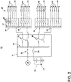
- FIG. 2 a schematic illustration is shown of an exemplary power distribution system 50 that can be utilized in the aircraft 10.
- the power distribution system 50 is shown having a set of power sources, such as the one or more of generators 18, a dischargeable or otherwise limited power source, such as supplemental power unit 32, the like, or a combination thereof.
- the supplemental power unit 32 can include a set of batteries 34. While a set of batteries 34 are shown, the supplemental power unit 32 can include any number or combination of power sources including limited power sources, as described herein.
- Each of the generator 18 and supplemental power unit 32 are connected with the primary distribution power bus 22 (e.g. such as the power bus 22 of FIG.
- each of the generator 18 or supplemental power unit 32 can be independently connectable to supply or otherwise energize the primary distribution power bus 22.
- the primary power distribution node 16 can include a number of outputs connected with a respective set or subset of secondary power distribution nodes 30 to define a hierarchical topography for the power distribution system 50.
- each output connectable with a respective secondary power distribution node 30 can be selectively energized or otherwise supplied with power from the primary distribution power bus 22 by way of an independent primary distribution switch 40.
- the primary power distribution node 16 can include a set of primary power distribution switches 40.
- the output of each respective primary power distribution switch 40 can be connected with a secondary distribution power bus 42 of a respective secondary power distribution node 30, to energize or supply power to the respective secondary distribution power bus 42.
- Each secondary power distribution node 30 can further include a set of secondary distribution switches 44 connected to a respective set or subset of electrical loads 20.
- each electrical load 20 can be selectively energized by the secondary distribution power bus 42 by way of the respective secondary distribution switch 44.
- each electrical load 20 can be independently controllably or energizable, by way of the respective secondary distribution switch 44.
- at least a set or subset of the electrical loads 20 for at least one of the secondary power distribution nodes 30 can include at least one enabled electrical load 48, as defined herein.
- the electrical loads 20 are further shown having at least one typical or conventional electrical load 46, which is not utilized during an idle state, as described herein.
- Non-limiting aspects of the disclosure can be included wherein at least a subset of the enabled electrical loads 48 are operable in by consuming a constant power over a period of time.
- at least a subset of the enabled electrical loads 48 are temporarily operable, such as for interval periods of time.
- the temporarily operable state of the subset of the enabled electrical loads 48 can be periodic, or in response to commands to operate on-demand, for example.
- a combination of operable and temporarily operable subsets of the enabled electrical loads 48 can be included.
- the power distribution system 50 can be energized or otherwise supplied by the generator 18, by way of an operating turbine engine, and connectable with the primary power distribution node 16 by way of the generator switch 36.
- the power distribution system 50 can distribute the power through the primary power distribution node 16, the secondary power distribution nodes 30, or a subset thereof, to the set of electrical loads 20, 46, 48, as needed based on operational demands of the system 50.
- Non-limiting aspects of the disclosure can further be included wherein the supplemental power unit 32 can further energize or otherwise supply power to primary power distribution node 16, or supplement the power supplied by the generator 18, by way of the supplemental power unit switch 38.
- the supplemental power unit 32 can additionally or alternatively be rechargeable by power supplied by way of the generator 18, for example, by way of the primary distribution power bus 22.
- the generator 18 would not typically be operation, and consequently, would not typically supply power or otherwise energize the primary power distribution node 16, or any downstream secondary power distribution nodes 30 or electrical loads 20.
- the supplemental power unit 32 can operably supply at least a portion of power to the power distribution system 50 to meet the power demands of at least one enabled electrical load 48, or a set of enabled electrical loads 48, as defined herein.
- Non-limiting aspects of the disclosure can further be included wherein the supplemental power unit 32 can operably supply at least a portion of power to the power distribution system 50 to meet the further power demands of a subset of conventional electrical loads 46, a subset of enabled electrical loads 48, a subset of secondary power distribution nodes 30, a combination thereof, or the like.
- the respective set of primary distribution switch 40 the respective set of secondary distribution switches 44, subsets thereof, or the like, will consume power from the supplemental power unit 32.
- the various sets or subsets of switches 36, 38, 40, 44 are operably in an open state (e.g. a non-conducting mode)
- leakage currents can be conducted through or across the sets or subsets of switches 36, 38, 40, 44 that otherwise are difficult to avoid.
- the leakage currents can summate to a large power dissipation or consumption of power over a period of time.
- an aircraft power distribution system can include a hierarchical switch topology that distributes power to thousands of electrical loads. In this example, a thousand (or more) switches, each consuming even a small leakage current in the open non-conducting state, would summate to a much larger overall power consumption.
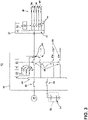
- FIG. 3 illustrates a further detailed schematic view of the power distribution system of the aircraft of FIG. 2 .
- a single secondary power distribution node 30 is shown for brevity and ease of understanding, but aspects of the disclosure are applicable to each, or a subset of, the secondary power distribution nodes 30.
- the primary power distribution node 16 further includes a primary distribution node power source 58 connected with and adapted to receive a first power from the primary distribution power bus 22.
- the primary distribution node power source 58 can further be connected with each respective output connected or otherwise connectable with each respective secondary power distribution node 30.
- the primary distribution node power source 58 can supply a second power to a set of outputs 60, each output 60 electrical downstream of a respective primary distribution switch 40, and upstream of the respective secondary power distribution node 30.
- the set of outputs 60 can be electrically in line with a respective diode 62 enabling unidirectional power supplying from the primary distribution node power source 58 to the set of outputs 60.
- the second power can be less than or lower than the first power, can meet a power demand for the downstream components, or a combination thereof.
- non-limiting aspects of the disclosure can include a controller module 56 of the primary power distribution node 16, or associated with the primary power distribution node 16, and communicatively connected with the primary distribution node power source 58, and operably connected with each respective primary distribution switch 40.
- the controller module 56 can enable, enforce, operation, or otherwise control the independent or common operation of the set or a subset of the primary distribution switches 40.
- the controller module 56 can include a processor and memory.
- the controller module 56 can be further connected with additional power distribution controller modules to operate a power distribution system 50 control schema.
- the additional power distribution controller modules can include local control modules, networked control modules, remote control modules that can provide commands and instructions from a remote location away from the power distribution system 50, or a combination thereof.
- the secondary power distribution node 30 is further shown including a secondary distribution node power source 54 communicatively connected with a controller module 52 of the secondary power distribution node 30, and operably connected with each respective secondary distribution switch 44.
- the controller module 52 which can be similar to the controller module 56 of the primary power distribution node 16, can enable, enforce, operation, or otherwise control the independent or common operation of the set or a subset of the secondary distribution switches 44.
- the primary distribution power bus 22 can supply power to the primary distribution node power source 58, which can in turn supply power to the controller module 56 to operate switching operations for the primary power distribution node 16, as needed.
- energized secondary power distribution node 30 includes an energized secondary distribution power bus 42, which can supply power to the secondary distribution power source 54.
- the secondary distribution power source 54 can in turn supply power to the controller module 52 to operate switching operations for the secondary power distribution node 30, as needed.
- aspects of the disclosure can operably enable a low power consumption or low power dissipation power distribution system 50.
- the primary distribution power bus 22 can be energized by or receive power from the supplemental power unit 34.
- the primary distribution power bus 22 can energize or further supply power to the primary distribution node power source 58.
- the primary distribution node power source 58 can selectively, independently, or operably supply power to respective outputs 60, as needed, as well as to supply power to the controller module 56 to operate switching operations for the primary power distribution node 16, as needed.
- a respective secondary power distribution node 30 that does not include any active or enabled electrical loads 48 would not typically receive power from the primary power distribution node 16, such that the connecting primary distribution switch 40 would be set to an open non-conducting state, for example, by the controller module 56. This would otherwise result in leakage current being dissipated through the open non-conductive switch 40, as explained herein.
- Non-limiting aspects of the disclosure can be included wherein, for example, the primary distribution node power source 58 enables, supplies, or provides a low voltage to the respective output 60 associated with the secondary power distribution node 30 without any active or enabled electrical loads 48.
- a "low voltage” is a voltage less than the typical voltage supplied by the power supply during normal (non-idle) power distribution system 50 operations (i.e. a "high voltage").
- a respectively "low voltage” could be an order of magnitude smaller, such as 10 Volts DC or 30 Volts DC, or the like.
- the controller module 52 of the secondary power distribution node 30 can be configured or selected such that the controller module 52 can be operable in response to the low voltage (supplied by way of the secondary distribution power bus 42 to the secondary distribution node power source 54). In this sense, the controller module 52 can be "active" due to a regular power supply, even in idle states of the power distribution system 50.
- This "active" state which for example, can include a “sleep” state, a “standby” state, or a low power consumptions state, and can allow the controller module 52 to remain alert in case of monitoring or other operative tasks that may occur in a periodic, temporary, on-demand, or otherwise irregular operation, as opposed to continuous operation(s).
- Additional non-limiting examples can include remote activation of the controller module 52 in the sleep or standby state, such as by way of networked operations or commands, "wake on local area network (LAN)” commands, or the like. This can reduce a delay in power-up, power-on, start-up, boot-up routines, or the like, and result in an overall more-responsive system, compared to if the controller module 52 was otherwise inactive.
- Starting up a controller module can take an appreciable amount of time, and delay implementing any commands from the controller module.
- enabling the powering of the controller module 52 can be included as an enabled electrical load 48, such that the low power operation of the controller module 52 is desirable, even during the idle state.
- Non-limiting aspects of the disclosure can be further included wherein, for example, the primary power distribution node 16 operably supplies power or otherwise energizes the respective secondary power distribution nodes 30 with any active or enabled electrical loads 48.
- the power distribution system 50 can identify or otherwise account for a subset of the electrical loads 20, such as the active or enable electrical loads 48 that are operable or energized during the idle state, and can, for example, control the respective primary distribution switch 40 to close or operate in a conductive state, to energize the secondary power distribution node 30, which can further distribute the power to the active or enabled electrical load(s) 48.
- the power distribution system 50 is operable in an idle or low power consumption state, wherein secondary power distribution nodes 30 with enabled electrical loads 48 are energized as needed, and wherein secondary power distribution nodes 30 without enabled electrical loads 48 can be switchably disabled, and powered by a low voltage that reduces power consumption or power dissipation otherwise due to leakage currents through the respective set of open or non-conducting switches.
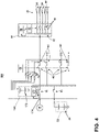
- FIG. 4 another power distribution system 150 according to another aspect of the present disclosure.
- the power distribution system 150 is similar to the power distribution system 50; therefore, like parts will be identified with like numerals increased by 100, with it being understood that the description of the like parts of the power distribution system 50 applies to the power distribution system 50, unless otherwise noted.
- the primary distribution node power source 158 can further include a separate and independent power supply 172, shown in one example to include a set of batteries, or a set of low voltage batteries. In this sense, the primary power distribution power source 158 can independently supply power to the respective set of outputs 60, as described, without the primary distribution power bus 22 being energized, by, for instance, the supplemental power unit 32.
- the primary distribution power source 158 can include a recharging controller 170 connectable with the independent power supply 172 and the primary distribution power bus 22 by way of a recharging switch 174.
- the independent power supply 172 can be selectively recharged by way of the primary distribution power bus 22 (via the recharging switch 174), which can further be temporarily energized by the supplemental power unit 32 or the generator 18 (if available).
- the recharging switch 174 can be controllably opened, as can the supplemental power unit 32, if desired.
- FIG. 5 another power distribution system 250 according to another aspect of the present disclosure.
- the power distribution system 250 is similar to the power distribution system 50; therefore, like parts will be identified with like numerals increased by 200, with it being understood that the description of the like parts of the power distribution system 50 applies to the power distribution system 250, unless otherwise noted.
- One difference is that the secondary power distribution node 230 can selectively operate to supply different voltages based on the current operating condition.
- the parallel components can include a conductor 284 that passes the input received to a first output, a voltage converter 280, such as a high voltage to low voltage converter, which converts high voltage received at the input to a lower relative voltage supplied to a second output, and a voltage control 282 that operably controls a voltage controlled switch 286 connectable to either the first output or the second output, and further connected with the secondary distribution power bus 42.
- the secondary power distribution node 230 is operable in response to receiving a high voltage, such as voltage supplied by the primary power distribution node 16 during idle state power distribution system 250 operation.
- the voltage controller 282 can sense the high voltage received at the parallel input, and operate the voltage controlled switch 286 to connect the output of the voltage converter 280 with the secondary distribution power bus 42.
- the secondary power distribution node 230 is operable in response to receiving a low voltage, such as voltage supplied by the primary power distribution node 16 during idle state power distribution system 250 operation (e.g. as shown and explained with reference to FIG. 3 , FIG. 4 , or a combination thereof).
- the voltage controller 282 can sense the low voltage received at the parallel input, and operate the voltage controlled switch 286 to connect the output of the conductor 284 with the secondary distribution power bus 42, passing the low voltage to the secondary distribution power bus 42.
- the enable electrical load(s) 48 are operable under a low voltage
- aspects of the disclosure can operably allow for the powering of these enabled electrical load(s) 48 by the secondary power distribution nod 230. In this sense, the low voltage supplied by the primary distribution node power source 58 to the secondary power distribution node 230 can be selected or matched with the power demands of the enabled electrical loads 48.
- aspects of the disclosure can be included to define a method of reducing leakage current in a power distribution system 50, 150, 250.
- the method of reducing leakage current can include first identifying a subset of electrical loads 20 desired to be energized during an idle state of the power distribution system 50, 150, 250, defining a set of enabled electrical loads 48. Next the method can include identifying a subset of secondary power distribution nodes 30, 230 not associated with or not powering any active or enabled electrical loads 48.
- the method then procedures to operably or switchably disconnecting the subset of secondary power distribution nodes 30, 230 from a limited power supply, such as at least one of the supplemental power unit 32 or the primary distribution power source 158, by way of opening a primary distribution switch 40 positioned in a primary power distribution node 16 upstream of the subset of secondary power distribution nodes 30, 230. Finally, the method continues by supplying a low voltage power supply to the output 60 of the opened primary power distribution switch 40, wherein the low voltage power supply reduces leakage current across the primary distribution switch 40.
- a limited power supply such as at least one of the supplemental power unit 32 or the primary distribution power source 158
- non-limiting aspects of the disclosure can be included further comprising identifying a second subset of secondary power distribution nodes 30, 230 associated with at least a subset of the enabled electrical loads 48, and switchably connecting the second subset of secondary power distribution nodes 30, 230 with the limited power supply, such as the supplemental power unit 32 or the primary distribution power source 158, to operably energize the subset of the enabled electrical loads 48.
- the method can be included wherein the subset of enabled electrical loads 48 includes at least one of a monitoring load, and security monitoring load, a power-operated door load, or a lighting load.
- the method can be included wherein the subset of secondary power distribution nodes 30, 230 further includes a controller module 52 configured to controllably operate switching operations of each respective secondary power distribution node 30, 230, and wherein the supplied low voltage power supply is sufficient to operate the controller module 52, such as in a lower power consumption standby or sleep mode.
- the method can be included, wherein the limited power supply includes a dischargeable power supply.
- the aspects disclosed herein provide a method and power distribution system operable in a low power dissipation or low power consumption state, such as an idle state.
- the technical effect is that the above described aspects enable the power distribution system to be able to distribute and control power to a large number of electrical loads using solid state technology with minimal current leakage, while maintaining a rapid response to changing power demands.
Landscapes
- Engineering & Computer Science (AREA)
- Power Engineering (AREA)
- Aviation & Aerospace Engineering (AREA)
- Direct Current Feeding And Distribution (AREA)
- Supply And Distribution Of Alternating Current (AREA)
Priority Applications (1)
| Application Number | Priority Date | Filing Date | Title |
|---|---|---|---|
| EP24174508.2A EP4387036A3 (fr) | 2020-11-18 | 2021-11-10 | Système et procédé de fonctionnement d'un système de distribution d'énergie |
Applications Claiming Priority (1)
| Application Number | Priority Date | Filing Date | Title |
|---|---|---|---|
| GB2018124.4A GB2601129B (en) | 2020-11-18 | 2020-11-18 | System and method for operating a power distribution system |
Related Child Applications (2)
| Application Number | Title | Priority Date | Filing Date |
|---|---|---|---|
| EP24174508.2A Division EP4387036A3 (fr) | 2020-11-18 | 2021-11-10 | Système et procédé de fonctionnement d'un système de distribution d'énergie |
| EP24174508.2A Division-Into EP4387036A3 (fr) | 2020-11-18 | 2021-11-10 | Système et procédé de fonctionnement d'un système de distribution d'énergie |
Publications (3)
| Publication Number | Publication Date |
|---|---|
| EP4002630A2 true EP4002630A2 (fr) | 2022-05-25 |
| EP4002630A3 EP4002630A3 (fr) | 2022-06-01 |
| EP4002630B1 EP4002630B1 (fr) | 2024-06-12 |
Family
ID=74046576
Family Applications (2)
| Application Number | Title | Priority Date | Filing Date |
|---|---|---|---|
| EP24174508.2A Pending EP4387036A3 (fr) | 2020-11-18 | 2021-11-10 | Système et procédé de fonctionnement d'un système de distribution d'énergie |
| EP21207569.1A Active EP4002630B1 (fr) | 2020-11-18 | 2021-11-10 | Système et procédé de fonctionnement d'un système de distribution d'énergie |
Family Applications Before (1)
| Application Number | Title | Priority Date | Filing Date |
|---|---|---|---|
| EP24174508.2A Pending EP4387036A3 (fr) | 2020-11-18 | 2021-11-10 | Système et procédé de fonctionnement d'un système de distribution d'énergie |
Country Status (4)
| Country | Link |
|---|---|
| US (2) | US11691754B2 (fr) |
| EP (2) | EP4387036A3 (fr) |
| CN (1) | CN114520505B (fr) |
| GB (1) | GB2601129B (fr) |
Families Citing this family (6)
| Publication number | Priority date | Publication date | Assignee | Title |
|---|---|---|---|---|
| GB2601129B (en) * | 2020-11-18 | 2023-05-31 | Ge Aviat Systems Ltd | System and method for operating a power distribution system |
| CN113895275B (zh) * | 2021-11-15 | 2023-07-18 | 华为数字能源技术有限公司 | 功率分配设备以及充电系统 |
| EP4358405A1 (fr) * | 2022-10-18 | 2024-04-24 | HS Elektronik Systeme GmbH | Contrôleur de puissance à l'état solide d'un aéronef et procédé de fonctionnement d'un contrôleur de puissance à l'état solide d'un aéronef |
| US12438365B2 (en) * | 2024-02-13 | 2025-10-07 | Ford Global Technologies, Llc | Power distribution management for a vehicle |
| CN119341042B (zh) * | 2024-09-29 | 2025-10-31 | 河海大学 | 一种中低压配电系统多层级自治运行调控方法 |
| CN119418504B (zh) * | 2024-10-31 | 2025-10-24 | 广东电网有限责任公司 | 一种多层级有源配电网剩余电流预警方法及装置 |
Family Cites Families (18)
| Publication number | Priority date | Publication date | Assignee | Title |
|---|---|---|---|---|
| US7538454B2 (en) | 2005-06-30 | 2009-05-26 | Honeywell International Inc. | Leakage current shunt in an electrical power distribution system utilizing solid state relays |
| FR2900637B1 (fr) | 2006-05-04 | 2009-02-13 | Airbus France Sas | Dispositif et procede pour gerer l'activation ou la desactivation des alimentations electriques des systemes electriques a bord d'un aeronef |
| US7598625B2 (en) | 2007-06-08 | 2009-10-06 | Honeywell International Inc. | Network-based aircraft secondary electric power distribution system |
| US8861162B2 (en) | 2010-03-09 | 2014-10-14 | Honeywell International Inc. | High power solid state power controller (SSPC) solution for primary power distribution applications |
| DE102010035278B4 (de) | 2010-08-24 | 2020-07-09 | Hamilton Sundstrand Corporation | Schaltung zur Verringerung von Wechselstrom-Leckstrom |
| US8738268B2 (en) * | 2011-03-10 | 2014-05-27 | The Boeing Company | Vehicle electrical power management and distribution |
| US9327600B1 (en) | 2011-09-06 | 2016-05-03 | Neeme Systems Solutions, Inc. | Aircraft utilities and power distribution system |
| WO2017000981A1 (fr) * | 2015-06-29 | 2017-01-05 | Ge Aviation Systems Limited | Circuit passif de gestion de fuite pour courant de fuite de commutateur |
| GB2541451B (en) * | 2015-08-20 | 2018-11-28 | Ge Aviat Systems Ltd | Systems, methods, and devices for bipolar high voltage direct current electrical power distribution |
| EP3154143B1 (fr) * | 2015-10-07 | 2023-08-23 | GE Aviation Systems Limited | Système de protection de secours contre les surcharges pour contrôleur de puissance à sémi-conducteurs |
| GB2552982B (en) | 2016-08-17 | 2019-12-11 | Ge Aviat Systems Ltd | Method and apparatus for arranging fuses in a printed circuit board |
| GB2552983B (en) * | 2016-08-17 | 2021-04-07 | Ge Aviat Systems Ltd | Method and apparatus for detecting an electrical fault in a printed circuit board |
| GB2559956B (en) * | 2017-02-15 | 2020-09-16 | Ge Aviat Systems Ltd | Power distribution node for a power architecture |
| EP3389185B1 (fr) | 2017-04-11 | 2020-11-25 | HS Elektronik Systeme GmbH | Commande de puissance monolithique |
| US10942527B2 (en) | 2017-05-30 | 2021-03-09 | Textron Innovations Inc. | System and method for controlling rotorcraft load priority |
| GB2563839B (en) * | 2017-06-26 | 2020-11-18 | Ge Aviat Systems Ltd | System and method for limiting currents in a power distribution system |
| GB2574666B (en) * | 2018-06-15 | 2022-11-30 | Ge Aviat Systems Ltd | Method and apparatus for no-break power transfer in a power distribution system |
| GB2601129B (en) * | 2020-11-18 | 2023-05-31 | Ge Aviat Systems Ltd | System and method for operating a power distribution system |
-
2020
- 2020-11-18 GB GB2018124.4A patent/GB2601129B/en active Active
-
2021
- 2021-11-09 US US17/522,502 patent/US11691754B2/en active Active
- 2021-11-10 EP EP24174508.2A patent/EP4387036A3/fr active Pending
- 2021-11-10 EP EP21207569.1A patent/EP4002630B1/fr active Active
- 2021-11-17 CN CN202111360158.6A patent/CN114520505B/zh active Active
-
2023
- 2023-06-06 US US18/330,140 patent/US12179935B2/en active Active
Also Published As
| Publication number | Publication date |
|---|---|
| US20220153428A1 (en) | 2022-05-19 |
| CN114520505B (zh) | 2026-01-30 |
| US11691754B2 (en) | 2023-07-04 |
| CN114520505A (zh) | 2022-05-20 |
| US12179935B2 (en) | 2024-12-31 |
| EP4387036A2 (fr) | 2024-06-19 |
| GB202018124D0 (en) | 2020-12-30 |
| US20230312127A1 (en) | 2023-10-05 |
| EP4002630A3 (fr) | 2022-06-01 |
| GB2601129B (en) | 2023-05-31 |
| GB2601129A (en) | 2022-05-25 |
| EP4002630B1 (fr) | 2024-06-12 |
| EP4387036A3 (fr) | 2024-06-26 |
Similar Documents
| Publication | Publication Date | Title |
|---|---|---|
| US12179935B2 (en) | System and method for operating a power distribution system | |
| CN108069036B (zh) | 用于多电飞机的电力系统 | |
| US20200042062A1 (en) | Dynamically configurable energy storage unit | |
| KR101516193B1 (ko) | 태양광 충전 제어 장치 및 그 제어 방법 | |
| CN107592952B (zh) | 用于配电的系统和方法 | |
| US8975784B2 (en) | Method for managing an electrical network | |
| CN102113191B (zh) | 用于最大化电池充电时间的直流功率控制 | |
| RU2418721C2 (ru) | Система электропитания для электроснабжения по меньшей мере одного потребителя на летательном аппарате | |
| KR102048047B1 (ko) | 태양광 기반의 자율 독립형 마이크로그리드 시스템 및 그 운전방법 | |
| US10691149B2 (en) | Controller and method for operating a power distribution system | |
| US11605957B2 (en) | Dynamic power supply system | |
| KR20040097138A (ko) | 섬 네트워크 및 섬 네트워크를 운영하는 방법 | |
| WO2012162570A1 (fr) | Système et procédé pour intégrer et gérer une demande/réponse entre des sources d'énergie alternative, un réseau électrique et des charges | |
| EP3582364B1 (fr) | Procédé et appareil pour transfer d'énergie sans rupture dans un système de distribution de puissance | |
| Karunarathne et al. | Fuzzy logic control strategy for fuel cell/battery aerospace propulsion system | |
| US11731777B2 (en) | Control circuit for a power distribution node | |
| CN106160162A (zh) | 供电系统 | |
| KR20190062812A (ko) | 에너지 저장 시스템 | |
| JP5864247B2 (ja) | 発電装置 | |
| CN107069930A (zh) | 一种无人机能量调理电路及方法 | |
| Sathyan et al. | Hybrid wind/PV/fuel cell generation system | |
| JPH09312935A (ja) | 電力貯蔵式電源システムおよび電力貯蔵方法 | |
| JP7165507B2 (ja) | 直流給電システム | |
| Breit | Improved Energy Management System for Airplane Electrical Power | |
| JP7775070B2 (ja) | 電力システム |
Legal Events
| Date | Code | Title | Description |
|---|---|---|---|
| PUAI | Public reference made under article 153(3) epc to a published international application that has entered the european phase |
Free format text: ORIGINAL CODE: 0009012 |
|
| STAA | Information on the status of an ep patent application or granted ep patent |
Free format text: STATUS: THE APPLICATION HAS BEEN PUBLISHED |
|
| PUAL | Search report despatched |
Free format text: ORIGINAL CODE: 0009013 |
|
| AK | Designated contracting states |
Kind code of ref document: A2 Designated state(s): AL AT BE BG CH CY CZ DE DK EE ES FI FR GB GR HR HU IE IS IT LI LT LU LV MC MK MT NL NO PL PT RO RS SE SI SK SM TR |
|
| AK | Designated contracting states |
Kind code of ref document: A3 Designated state(s): AL AT BE BG CH CY CZ DE DK EE ES FI FR GB GR HR HU IE IS IT LI LT LU LV MC MK MT NL NO PL PT RO RS SE SI SK SM TR |
|
| RIC1 | Information provided on ipc code assigned before grant |
Ipc: H02J 4/00 20060101ALI20220425BHEP Ipc: B64D 41/00 20060101ALI20220425BHEP Ipc: H02J 3/14 20060101AFI20220425BHEP |
|
| STAA | Information on the status of an ep patent application or granted ep patent |
Free format text: STATUS: REQUEST FOR EXAMINATION WAS MADE |
|
| 17P | Request for examination filed |
Effective date: 20221130 |
|
| RBV | Designated contracting states (corrected) |
Designated state(s): AL AT BE BG CH CY CZ DE DK EE ES FI FR GB GR HR HU IE IS IT LI LT LU LV MC MK MT NL NO PL PT RO RS SE SI SK SM TR |
|
| GRAP | Despatch of communication of intention to grant a patent |
Free format text: ORIGINAL CODE: EPIDOSNIGR1 |
|
| STAA | Information on the status of an ep patent application or granted ep patent |
Free format text: STATUS: GRANT OF PATENT IS INTENDED |
|
| RIC1 | Information provided on ipc code assigned before grant |
Ipc: H02J 4/00 20060101ALI20231212BHEP Ipc: H02J 3/14 20060101AFI20231212BHEP |
|
| INTG | Intention to grant announced |
Effective date: 20240109 |
|
| GRAS | Grant fee paid |
Free format text: ORIGINAL CODE: EPIDOSNIGR3 |
|
| GRAA | (expected) grant |
Free format text: ORIGINAL CODE: 0009210 |
|
| STAA | Information on the status of an ep patent application or granted ep patent |
Free format text: STATUS: THE PATENT HAS BEEN GRANTED |
|
| AK | Designated contracting states |
Kind code of ref document: B1 Designated state(s): AL AT BE BG CH CY CZ DE DK EE ES FI FR GB GR HR HU IE IS IT LI LT LU LV MC MK MT NL NO PL PT RO RS SE SI SK SM TR |
|
| REG | Reference to a national code |
Ref country code: GB Ref legal event code: FG4D |
|
| REG | Reference to a national code |
Ref country code: CH Ref legal event code: EP |
|
| REG | Reference to a national code |
Ref country code: DE Ref legal event code: R096 Ref document number: 602021014298 Country of ref document: DE |
|
| P01 | Opt-out of the competence of the unified patent court (upc) registered |
Effective date: 20240525 |
|
| REG | Reference to a national code |
Ref country code: IE Ref legal event code: FG4D |
|
| PG25 | Lapsed in a contracting state [announced via postgrant information from national office to epo] |
Ref country code: BG Free format text: LAPSE BECAUSE OF FAILURE TO SUBMIT A TRANSLATION OF THE DESCRIPTION OR TO PAY THE FEE WITHIN THE PRESCRIBED TIME-LIMIT Effective date: 20240612 |
|
| PG25 | Lapsed in a contracting state [announced via postgrant information from national office to epo] |
Ref country code: HR Free format text: LAPSE BECAUSE OF FAILURE TO SUBMIT A TRANSLATION OF THE DESCRIPTION OR TO PAY THE FEE WITHIN THE PRESCRIBED TIME-LIMIT Effective date: 20240612 Ref country code: FI Free format text: LAPSE BECAUSE OF FAILURE TO SUBMIT A TRANSLATION OF THE DESCRIPTION OR TO PAY THE FEE WITHIN THE PRESCRIBED TIME-LIMIT Effective date: 20240612 |
|
| REG | Reference to a national code |
Ref country code: LT Ref legal event code: MG9D |
|
| PG25 | Lapsed in a contracting state [announced via postgrant information from national office to epo] |
Ref country code: GR Free format text: LAPSE BECAUSE OF FAILURE TO SUBMIT A TRANSLATION OF THE DESCRIPTION OR TO PAY THE FEE WITHIN THE PRESCRIBED TIME-LIMIT Effective date: 20240913 |
|
| REG | Reference to a national code |
Ref country code: NL Ref legal event code: MP Effective date: 20240612 |
|
| PG25 | Lapsed in a contracting state [announced via postgrant information from national office to epo] |
Ref country code: ES Free format text: LAPSE BECAUSE OF FAILURE TO SUBMIT A TRANSLATION OF THE DESCRIPTION OR TO PAY THE FEE WITHIN THE PRESCRIBED TIME-LIMIT Effective date: 20240612 |
|
| PG25 | Lapsed in a contracting state [announced via postgrant information from national office to epo] |
Ref country code: LV Free format text: LAPSE BECAUSE OF FAILURE TO SUBMIT A TRANSLATION OF THE DESCRIPTION OR TO PAY THE FEE WITHIN THE PRESCRIBED TIME-LIMIT Effective date: 20240612 |
|
| PG25 | Lapsed in a contracting state [announced via postgrant information from national office to epo] |
Ref country code: NO Free format text: LAPSE BECAUSE OF FAILURE TO SUBMIT A TRANSLATION OF THE DESCRIPTION OR TO PAY THE FEE WITHIN THE PRESCRIBED TIME-LIMIT Effective date: 20240912 Ref country code: LV Free format text: LAPSE BECAUSE OF FAILURE TO SUBMIT A TRANSLATION OF THE DESCRIPTION OR TO PAY THE FEE WITHIN THE PRESCRIBED TIME-LIMIT Effective date: 20240612 Ref country code: HR Free format text: LAPSE BECAUSE OF FAILURE TO SUBMIT A TRANSLATION OF THE DESCRIPTION OR TO PAY THE FEE WITHIN THE PRESCRIBED TIME-LIMIT Effective date: 20240612 Ref country code: GR Free format text: LAPSE BECAUSE OF FAILURE TO SUBMIT A TRANSLATION OF THE DESCRIPTION OR TO PAY THE FEE WITHIN THE PRESCRIBED TIME-LIMIT Effective date: 20240913 Ref country code: FI Free format text: LAPSE BECAUSE OF FAILURE TO SUBMIT A TRANSLATION OF THE DESCRIPTION OR TO PAY THE FEE WITHIN THE PRESCRIBED TIME-LIMIT Effective date: 20240612 Ref country code: ES Free format text: LAPSE BECAUSE OF FAILURE TO SUBMIT A TRANSLATION OF THE DESCRIPTION OR TO PAY THE FEE WITHIN THE PRESCRIBED TIME-LIMIT Effective date: 20240612 Ref country code: BG Free format text: LAPSE BECAUSE OF FAILURE TO SUBMIT A TRANSLATION OF THE DESCRIPTION OR TO PAY THE FEE WITHIN THE PRESCRIBED TIME-LIMIT Effective date: 20240612 Ref country code: RS Free format text: LAPSE BECAUSE OF FAILURE TO SUBMIT A TRANSLATION OF THE DESCRIPTION OR TO PAY THE FEE WITHIN THE PRESCRIBED TIME-LIMIT Effective date: 20240912 |
|
| PG25 | Lapsed in a contracting state [announced via postgrant information from national office to epo] |
Ref country code: NL Free format text: LAPSE BECAUSE OF FAILURE TO SUBMIT A TRANSLATION OF THE DESCRIPTION OR TO PAY THE FEE WITHIN THE PRESCRIBED TIME-LIMIT Effective date: 20240612 |
|
| REG | Reference to a national code |
Ref country code: AT Ref legal event code: MK05 Ref document number: 1695039 Country of ref document: AT Kind code of ref document: T Effective date: 20240612 |
|
| PG25 | Lapsed in a contracting state [announced via postgrant information from national office to epo] |
Ref country code: NL Free format text: LAPSE BECAUSE OF FAILURE TO SUBMIT A TRANSLATION OF THE DESCRIPTION OR TO PAY THE FEE WITHIN THE PRESCRIBED TIME-LIMIT Effective date: 20240612 |
|
| PG25 | Lapsed in a contracting state [announced via postgrant information from national office to epo] |
Ref country code: PT Free format text: LAPSE BECAUSE OF FAILURE TO SUBMIT A TRANSLATION OF THE DESCRIPTION OR TO PAY THE FEE WITHIN THE PRESCRIBED TIME-LIMIT Effective date: 20241014 |
|
| PG25 | Lapsed in a contracting state [announced via postgrant information from national office to epo] |
Ref country code: PT Free format text: LAPSE BECAUSE OF FAILURE TO SUBMIT A TRANSLATION OF THE DESCRIPTION OR TO PAY THE FEE WITHIN THE PRESCRIBED TIME-LIMIT Effective date: 20241014 |
|
| PG25 | Lapsed in a contracting state [announced via postgrant information from national office to epo] |
Ref country code: PL Free format text: LAPSE BECAUSE OF FAILURE TO SUBMIT A TRANSLATION OF THE DESCRIPTION OR TO PAY THE FEE WITHIN THE PRESCRIBED TIME-LIMIT Effective date: 20240612 |
|
| PG25 | Lapsed in a contracting state [announced via postgrant information from national office to epo] |
Ref country code: EE Free format text: LAPSE BECAUSE OF FAILURE TO SUBMIT A TRANSLATION OF THE DESCRIPTION OR TO PAY THE FEE WITHIN THE PRESCRIBED TIME-LIMIT Effective date: 20240612 |
|
| PG25 | Lapsed in a contracting state [announced via postgrant information from national office to epo] |
Ref country code: IS Free format text: LAPSE BECAUSE OF FAILURE TO SUBMIT A TRANSLATION OF THE DESCRIPTION OR TO PAY THE FEE WITHIN THE PRESCRIBED TIME-LIMIT Effective date: 20241012 Ref country code: AT Free format text: LAPSE BECAUSE OF FAILURE TO SUBMIT A TRANSLATION OF THE DESCRIPTION OR TO PAY THE FEE WITHIN THE PRESCRIBED TIME-LIMIT Effective date: 20240612 |
|
| PG25 | Lapsed in a contracting state [announced via postgrant information from national office to epo] |
Ref country code: CZ Free format text: LAPSE BECAUSE OF FAILURE TO SUBMIT A TRANSLATION OF THE DESCRIPTION OR TO PAY THE FEE WITHIN THE PRESCRIBED TIME-LIMIT Effective date: 20240612 |
|
| PG25 | Lapsed in a contracting state [announced via postgrant information from national office to epo] |
Ref country code: RO Free format text: LAPSE BECAUSE OF FAILURE TO SUBMIT A TRANSLATION OF THE DESCRIPTION OR TO PAY THE FEE WITHIN THE PRESCRIBED TIME-LIMIT Effective date: 20240612 Ref country code: SK Free format text: LAPSE BECAUSE OF FAILURE TO SUBMIT A TRANSLATION OF THE DESCRIPTION OR TO PAY THE FEE WITHIN THE PRESCRIBED TIME-LIMIT Effective date: 20240612 |
|
| PG25 | Lapsed in a contracting state [announced via postgrant information from national office to epo] |
Ref country code: SM Free format text: LAPSE BECAUSE OF FAILURE TO SUBMIT A TRANSLATION OF THE DESCRIPTION OR TO PAY THE FEE WITHIN THE PRESCRIBED TIME-LIMIT Effective date: 20240612 |
|
| PG25 | Lapsed in a contracting state [announced via postgrant information from national office to epo] |
Ref country code: SM Free format text: LAPSE BECAUSE OF FAILURE TO SUBMIT A TRANSLATION OF THE DESCRIPTION OR TO PAY THE FEE WITHIN THE PRESCRIBED TIME-LIMIT Effective date: 20240612 Ref country code: SK Free format text: LAPSE BECAUSE OF FAILURE TO SUBMIT A TRANSLATION OF THE DESCRIPTION OR TO PAY THE FEE WITHIN THE PRESCRIBED TIME-LIMIT Effective date: 20240612 Ref country code: RO Free format text: LAPSE BECAUSE OF FAILURE TO SUBMIT A TRANSLATION OF THE DESCRIPTION OR TO PAY THE FEE WITHIN THE PRESCRIBED TIME-LIMIT Effective date: 20240612 Ref country code: PL Free format text: LAPSE BECAUSE OF FAILURE TO SUBMIT A TRANSLATION OF THE DESCRIPTION OR TO PAY THE FEE WITHIN THE PRESCRIBED TIME-LIMIT Effective date: 20240612 Ref country code: IS Free format text: LAPSE BECAUSE OF FAILURE TO SUBMIT A TRANSLATION OF THE DESCRIPTION OR TO PAY THE FEE WITHIN THE PRESCRIBED TIME-LIMIT Effective date: 20241012 Ref country code: EE Free format text: LAPSE BECAUSE OF FAILURE TO SUBMIT A TRANSLATION OF THE DESCRIPTION OR TO PAY THE FEE WITHIN THE PRESCRIBED TIME-LIMIT Effective date: 20240612 Ref country code: CZ Free format text: LAPSE BECAUSE OF FAILURE TO SUBMIT A TRANSLATION OF THE DESCRIPTION OR TO PAY THE FEE WITHIN THE PRESCRIBED TIME-LIMIT Effective date: 20240612 Ref country code: AT Free format text: LAPSE BECAUSE OF FAILURE TO SUBMIT A TRANSLATION OF THE DESCRIPTION OR TO PAY THE FEE WITHIN THE PRESCRIBED TIME-LIMIT Effective date: 20240612 |
|
| PG25 | Lapsed in a contracting state [announced via postgrant information from national office to epo] |
Ref country code: IT Free format text: LAPSE BECAUSE OF FAILURE TO SUBMIT A TRANSLATION OF THE DESCRIPTION OR TO PAY THE FEE WITHIN THE PRESCRIBED TIME-LIMIT Effective date: 20240612 |
|
| REG | Reference to a national code |
Ref country code: DE Ref legal event code: R097 Ref document number: 602021014298 Country of ref document: DE |
|
| PG25 | Lapsed in a contracting state [announced via postgrant information from national office to epo] |
Ref country code: DK Free format text: LAPSE BECAUSE OF FAILURE TO SUBMIT A TRANSLATION OF THE DESCRIPTION OR TO PAY THE FEE WITHIN THE PRESCRIBED TIME-LIMIT Effective date: 20240612 |
|
| PLBE | No opposition filed within time limit |
Free format text: ORIGINAL CODE: 0009261 |
|
| STAA | Information on the status of an ep patent application or granted ep patent |
Free format text: STATUS: NO OPPOSITION FILED WITHIN TIME LIMIT |
|
| 26N | No opposition filed |
Effective date: 20250313 |
|
| REG | Reference to a national code |
Ref country code: CH Ref legal event code: PL |
|
| PG25 | Lapsed in a contracting state [announced via postgrant information from national office to epo] |
Ref country code: MC Free format text: LAPSE BECAUSE OF FAILURE TO SUBMIT A TRANSLATION OF THE DESCRIPTION OR TO PAY THE FEE WITHIN THE PRESCRIBED TIME-LIMIT Effective date: 20240612 |
|
| PG25 | Lapsed in a contracting state [announced via postgrant information from national office to epo] |
Ref country code: LU Free format text: LAPSE BECAUSE OF NON-PAYMENT OF DUE FEES Effective date: 20241110 |
|
| REG | Reference to a national code |
Ref country code: CH Ref legal event code: PL |
|
| PG25 | Lapsed in a contracting state [announced via postgrant information from national office to epo] |
Ref country code: CH Free format text: LAPSE BECAUSE OF NON-PAYMENT OF DUE FEES Effective date: 20241130 |
|
| REG | Reference to a national code |
Ref country code: BE Ref legal event code: MM Effective date: 20241130 |
|
| PG25 | Lapsed in a contracting state [announced via postgrant information from national office to epo] |
Ref country code: SE Free format text: LAPSE BECAUSE OF FAILURE TO SUBMIT A TRANSLATION OF THE DESCRIPTION OR TO PAY THE FEE WITHIN THE PRESCRIBED TIME-LIMIT Effective date: 20240612 |
|
| PG25 | Lapsed in a contracting state [announced via postgrant information from national office to epo] |
Ref country code: BE Free format text: LAPSE BECAUSE OF NON-PAYMENT OF DUE FEES Effective date: 20241130 |
|
| PG25 | Lapsed in a contracting state [announced via postgrant information from national office to epo] |
Ref country code: IE Free format text: LAPSE BECAUSE OF NON-PAYMENT OF DUE FEES Effective date: 20241110 |
|
| PGFP | Annual fee paid to national office [announced via postgrant information from national office to epo] |
Ref country code: DE Payment date: 20251022 Year of fee payment: 5 |
|
| PGFP | Annual fee paid to national office [announced via postgrant information from national office to epo] |
Ref country code: GB Payment date: 20251022 Year of fee payment: 5 |
|
| PGFP | Annual fee paid to national office [announced via postgrant information from national office to epo] |
Ref country code: FR Payment date: 20251023 Year of fee payment: 5 |
|
| PG25 | Lapsed in a contracting state [announced via postgrant information from national office to epo] |
Ref country code: HU Free format text: LAPSE BECAUSE OF FAILURE TO SUBMIT A TRANSLATION OF THE DESCRIPTION OR TO PAY THE FEE WITHIN THE PRESCRIBED TIME-LIMIT; INVALID AB INITIO Effective date: 20211110 |
|
| PG25 | Lapsed in a contracting state [announced via postgrant information from national office to epo] |
Ref country code: CY Free format text: LAPSE BECAUSE OF FAILURE TO SUBMIT A TRANSLATION OF THE DESCRIPTION OR TO PAY THE FEE WITHIN THE PRESCRIBED TIME-LIMIT; INVALID AB INITIO Effective date: 20211110 |