EP4002645A1 - Appareil d'alimentation électrique et système d'alimentation électrique - Google Patents
Appareil d'alimentation électrique et système d'alimentation électrique Download PDFInfo
- Publication number
- EP4002645A1 EP4002645A1 EP19938843.0A EP19938843A EP4002645A1 EP 4002645 A1 EP4002645 A1 EP 4002645A1 EP 19938843 A EP19938843 A EP 19938843A EP 4002645 A1 EP4002645 A1 EP 4002645A1
- Authority
- EP
- European Patent Office
- Prior art keywords
- power supply
- obstruction
- power
- position information
- power reception
- Prior art date
- Legal status (The legal status is an assumption and is not a legal conclusion. Google has not performed a legal analysis and makes no representation as to the accuracy of the status listed.)
- Pending
Links
Images




Classifications
-
- H—ELECTRICITY
- H02—GENERATION; CONVERSION OR DISTRIBUTION OF ELECTRIC POWER
- H02J—ELECTRIC POWER NETWORKS; CIRCUIT ARRANGEMENTS OR SYSTEMS FOR SUPPLYING OR DISTRIBUTING ELECTRIC POWER; SYSTEMS FOR STORING ELECTRIC ENERGY
- H02J50/00—Circuit arrangements or systems for wireless supply or distribution of electric power
- H02J50/20—Circuit arrangements or systems for wireless supply or distribution of electric power using microwaves or radio frequency waves
-
- H—ELECTRICITY
- H02—GENERATION; CONVERSION OR DISTRIBUTION OF ELECTRIC POWER
- H02J—ELECTRIC POWER NETWORKS; CIRCUIT ARRANGEMENTS OR SYSTEMS FOR SUPPLYING OR DISTRIBUTING ELECTRIC POWER; SYSTEMS FOR STORING ELECTRIC ENERGY
- H02J50/00—Circuit arrangements or systems for wireless supply or distribution of electric power
- H02J50/60—Circuit arrangements or systems for wireless supply or distribution of electric power responsive to the presence of foreign objects, e.g. detection of living beings
-
- H—ELECTRICITY
- H02—GENERATION; CONVERSION OR DISTRIBUTION OF ELECTRIC POWER
- H02J—ELECTRIC POWER NETWORKS; CIRCUIT ARRANGEMENTS OR SYSTEMS FOR SUPPLYING OR DISTRIBUTING ELECTRIC POWER; SYSTEMS FOR STORING ELECTRIC ENERGY
- H02J50/00—Circuit arrangements or systems for wireless supply or distribution of electric power
- H02J50/20—Circuit arrangements or systems for wireless supply or distribution of electric power using microwaves or radio frequency waves
- H02J50/23—Circuit arrangements or systems for wireless supply or distribution of electric power using microwaves or radio frequency waves characterised by the type of transmitting antennas, e.g. directional array antennas or Yagi antennas
-
- H—ELECTRICITY
- H02—GENERATION; CONVERSION OR DISTRIBUTION OF ELECTRIC POWER
- H02J—ELECTRIC POWER NETWORKS; CIRCUIT ARRANGEMENTS OR SYSTEMS FOR SUPPLYING OR DISTRIBUTING ELECTRIC POWER; SYSTEMS FOR STORING ELECTRIC ENERGY
- H02J50/00—Circuit arrangements or systems for wireless supply or distribution of electric power
- H02J50/40—Circuit arrangements or systems for wireless supply or distribution of electric power using two or more transmitting or receiving devices
-
- H—ELECTRICITY
- H02—GENERATION; CONVERSION OR DISTRIBUTION OF ELECTRIC POWER
- H02J—ELECTRIC POWER NETWORKS; CIRCUIT ARRANGEMENTS OR SYSTEMS FOR SUPPLYING OR DISTRIBUTING ELECTRIC POWER; SYSTEMS FOR STORING ELECTRIC ENERGY
- H02J50/00—Circuit arrangements or systems for wireless supply or distribution of electric power
- H02J50/80—Circuit arrangements or systems for wireless supply or distribution of electric power involving the exchange of data, concerning supply or distribution of electric power, between transmitting devices and receiving devices
-
- H—ELECTRICITY
- H02—GENERATION; CONVERSION OR DISTRIBUTION OF ELECTRIC POWER
- H02J—ELECTRIC POWER NETWORKS; CIRCUIT ARRANGEMENTS OR SYSTEMS FOR SUPPLYING OR DISTRIBUTING ELECTRIC POWER; SYSTEMS FOR STORING ELECTRIC ENERGY
- H02J50/00—Circuit arrangements or systems for wireless supply or distribution of electric power
- H02J50/90—Circuit arrangements or systems for wireless supply or distribution of electric power involving detection or optimisation of position, e.g. alignment
Definitions
- the present invention relates to a power supply apparatus and a power supply system.
- a power supply apparatus outputs a radio wave, and a power reception apparatus receives the radio wave. By transmitting and receiving radio waves, power is supplied from the power supply apparatus to the power reception apparatus.
- a moving object may intervene between the power supply apparatus and the power reception apparatus.
- a moving object a moving obstruction
- the radio wave output from the power supply apparatus toward the power reception apparatus is blocked. That is, power supply processing is interrupted.
- the present invention provides a power supply apparatus capable of, regardless of the presence of a moving obstruction, preventing interruption of wireless power supply processing performed between the power supply apparatus and at least two or more power reception apparatuses.
- the present invention also provides a power supply system that includes the power supply apparatus.
- a power supply apparatus includes a power supply antenna, a directivity control unit, a position information acquisition unit, and a control unit.
- the power supply antenna is configured to emit, to a plurality of power reception apparatuses, a radio wave that is based on a power supply signal.
- the directivity control unit is configured to control directivity of the power supply antenna.
- the position information acquisition unit is configured to acquire position information indicating a position of an obstruction moving between the power supply antenna and at least one power reception apparatus of the plurality of power reception apparatuses. Based on the position information, the control unit is configured to determine a power reception apparatus, among the plurality of power reception apparatuses, to which power is to be supplied while avoiding the obstruction.
- the control unit is also configured to control the directivity control unit to steer the radio wave toward the determined power reception apparatus.
- the power supply apparatus is capable of preventing, regardless of the presence of a moving obstruction, interruption of wireless power supply processing performed between the power supply apparatus and the plurality of power reception apparatuses.
- a power supply system includes a plurality of power reception apparatuses, a power supply apparatus, and an obstruction position detection apparatus.
- the power supply apparatus is configured to supply power wirelessly to the plurality of power reception apparatuses.
- the obstruction position detection apparatus is configured to make a detection of a position of an obstruction moving between the power supply apparatus and at least one power reception apparatus of the plurality of power reception apparatuses.
- the obstruction position detection apparatus is configured to transmit a result of the detection to the power supply apparatus as position information.
- the power supply apparatus includes a power supply antenna, a directivity control unit, a position information acquisition unit, and a control unit.
- the power supply antenna is configured to emit, to a plurality of power reception apparatuses, a radio wave that is based on a power supply signal.
- the directivity control unit is configured to control directivity of the power supply antenna.
- the position information acquisition unit is configured to acquire position information from the obstruction position detection apparatus. Based on the position information, the control unit is configured to determine a power reception apparatus, among the plurality of power reception apparatuses, to which power is to be supplied while avoiding the obstruction.
- the control unit is configured to control the directivity control unit to steer the radio wave toward the determined power reception apparatus.
- the power supply system is capable of preventing, regardless of the presence of a moving obstruction, interruption of wireless power supply processing performed between the power supply apparatus and the plurality of power reception apparatuses.
- the power supply system is also capable of controlling the directivity of the power supply antenna in consideration of the actual position of the moving obstruction.
- a power supply system includes a plurality of power reception apparatuses, a power supply apparatus, and an obstruction control apparatus.
- the power supply apparatus is configured to supply power wirelessly to the plurality of power reception apparatuses.
- the obstruction control apparatus is configured to perform control of movement of an obstruction moving between the power supply apparatus and at least one power reception apparatus of the plurality of power reception apparatuses.
- the obstruction control apparatus is configured to transmit, to the power supply apparatus, position information indicating a position of the obstruction identified based on the control.
- the power supply apparatus includes a power supply antenna, a directivity control unit, a position information acquisition unit, and a control unit.
- the power supply antenna is configured to emit, to a plurality of power reception apparatuses, a radio wave that is based on a power supply signal.
- the directivity control unit is configured to control directivity of the power supply antenna.
- the position information acquisition unit is configured to acquire position information from the obstruction control apparatus. Based on the position information, the control unit is configured to determine a power reception apparatus, among the plurality of power reception apparatuses, to which power is to be supplied while avoiding the obstruction.
- the control unit is configured to control the directivity control unit to steer the radio wave toward the determined power reception apparatus.
- the power supply system is capable of preventing, regardless of the presence of a moving obstruction, interruption of wireless power supply processing performed between the power supply apparatus and the plurality of power reception apparatuses.
- the power supply system is also capable of dynamically controlling the directivity of the power supply antenna by, instead of detecting the actual position of the obstruction, using the position of the obstruction identified based on the control of the movement of the obstruction by the obstruction control apparatus.
- a power supply apparatus is capable of preventing, regardless of the presence of a moving obstruction, interruption of wireless power supply processing performed between the power supply apparatus and at least two or more power reception apparatuses.
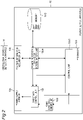
- FIG. 1 is a diagram illustrating a schematic configuration of a power supply system 100 according to the present embodiment.
- the power supply system 100 includes a plurality of power reception apparatuses 1, a power supply apparatus 10, and an obstruction position detection apparatus 11.
- the power supply apparatus 10 supplies power wirelessly to each of the power reception apparatuses 1.
- the power supply apparatus 10 In order to supply power, the power supply apparatus 10 outputs an electromagnetic wave (hereinafter referred to as radio wave) to each power reception apparatus 1.
- Each power reception apparatus 1 includes a power reception antenna 1a.
- a radio wave received by the power reception antenna 1a is converted into electrical energy.
- the power reception apparatus 1 is able to receive a supply of power.
- an obstruction 2 moves.
- the obstruction 2 moves along a direction 50.
- the obstruction 2 moves between the power supply apparatus 10 and at least one or more power reception apparatuses 1.
- the obstruction 2 moves between the power supply apparatus 10 (more specifically, the power supply antenna 10a) and each power reception apparatus 1 (more specifically, each power reception antenna 1a).
- the obstruction 2 when the obstruction 2 exists between the power supply apparatus 10 and a predetermined power reception apparatus 1, the obstruction 2 blocks the radio wave output from the power supply apparatus 10 to the predetermined power reception apparatus 1. That is, the obstruction 2 is a moving tangible object in the power supply system 100, and is capable of blocking radio waves output from the power supply apparatus 10 to the power reception apparatuses 1 in the power supply system 100. Thus, the power supply from the power supply apparatus 10 to the power reception apparatuses 1 can be blocked by the obstruction 2.
- the obstruction position detection apparatus 11 detects the position of the moving obstruction 2.
- the obstruction position detection apparatus 11 is communicably connected to the power supply apparatus 10. With this configuration, the obstruction position detection apparatus 11 is capable of transmitting the detection result (position information indicating the position of the obstruction 2) to the power supply apparatus 10. It is to be noted that the communication between the obstruction position detection apparatus 11 and the power supply apparatus 10 may be wired communication or wireless communication.
- the obstruction position detection apparatus 11 it is possible to employ any of various sensors, examples including a photoelectric sensor, a proximity sensor, an acceleration sensor, and a pressure sensor.
- the obstruction position detection apparatus 11 is also capable of detecting the position of the obstruction 2 using a signal from an RFID (radio frequency identifier) mounted on the obstruction 2.
- the obstruction position detection apparatus 11 may also be a device that includes various radars and/or a camera in order to detect the position of the obstruction 2.
- FIG. 2 is a diagram illustrating a specific configuration of the power supply apparatus 10. Next, a configuration of the power supply apparatus 10 will be described with reference to FIG. 2 .
- the power supply apparatus 10 which supplies power wirelessly to the power reception apparatuses 1, includes a power supply antenna 10a, a position information acquisition unit 10b, a processor 10c, a memory 10d, a power supply signal generation unit 10e, and a directivity control unit 10f.
- the power supply antenna 10a, the position information acquisition unit 10b, the memory 10d, the power supply signal generation unit 10e, and the directivity control unit 10f are connected to the processor 10c.
- the power supply antenna 10a emits, to each of the respective power reception apparatuses 1, a radio wave that is based on a power supply signal.
- the power supply antenna 10a may be an array antenna made up of a plurality of element antennas.
- the position information acquisition unit 10b is a communication unit, and is communicably connected to the obstruction position detection apparatus 11. With this configuration, the position information acquisition unit 10b acquires the above-described position information, which is the detection result acquired by the obstruction position detection apparatus 11.
- the power supply signal generation unit 10e includes a high-frequency circuit that generates power supply signals.
- the high-frequency circuit performs various kinds of processing, such as signal generation, distribution, amplification, and filtering.
- the directivity control unit 10f controls the directivity of the power supply antenna 10a. As described later, the directivity control unit 10f controls the directivity of the power supply antenna 10c4 so as to steer a radio wave to a power reception apparatus (power-supply-target power reception apparatus 1 to which power is to be supplied) 1 determined as power suppliable by the power reception apparatus determination unit 10a. By controlling the directivity, the main beam of the radio wave emitted from the power supply antenna 10a is directed to the power-supply-target power reception apparatus 1. That is, in the radio wave emitted from the power supply antenna 10a, the intensity of the beam in the direction toward the power-supply-target power reception apparatus 1 is maximized.
- the memory 10d which is a storage unit, stores various types of data.
- the memory 10d includes, for example, a random access memory (RAM) and a read only memory (ROM).
- RAM random access memory
- ROM read only memory
- the memory 10d stores various programs in a changeable manner.
- the memory 10d also stores, in a changeable manner, a correspondence relationship table D1 (see FIG. 4 ), which will be described later, and an obstruction position history information table D2 (see FIGs. 6 and 7 ), which will be described later.
- the processor 10c which is a control unit, includes a CPU (Central Processing Unit). For example, the processor 10c reads programs and data stored in the memory 10d. Based on a program that has been read, the processor 10c controls the power supply antenna 10a, the position information acquisition unit 10b, the memory 10d, the power supply signal generation unit 10e, and the directivity control unit 10f to execute a predetermined operation and a predetermined function. Also based on a program that has been read, the processor 10c performs predetermined calculation, analysis, processing, and control in blocks 10c1 and 10c4, which are implemented by the program in the processor 10c.
- a CPU Central Processing Unit
- the processor 10c includes, as functional blocks, an overall control unit 10c1 and a power reception apparatus determination unit 10c4.
- the overall control unit 10c1 controls operation timings of, for example, the position information acquisition unit 10b, the memory 10d, the power supply signal generation unit 10e, and the directivity control unit 10f.
- the power reception apparatus determination unit 10c4 determines a power-supply-target power reception apparatus 1, among the plurality of power reception apparatuses 1, to which power is to be supplied. More specifically, the power reception apparatus determination unit 10c4 determines the power-supply-target power reception apparatus 1 using the position information and the data stored in the memory 10d (the correspondence relationship table D1 and the obstruction position history information table D2).
- the power-supply-target power reception apparatus I means a power reception apparatus 1 capable of receiving wireless power supply from the power supply apparatus 10 while avoiding the obstruction 2 (without being affected by radio wave blocking by the obstruction 2). Between the determined power-supply-target power reception apparatus 1 and the power supply apparatus 10, the supply of radio wave from the power supply apparatus 10 is not interrupted by the obstruction 2 existing at the position identified by the position information.
- the power reception apparatus determination unit 10c4 controls the directivity control unit 10f to steer a radio wave to the power-supply-target power reception apparatus 1.
- the directivity control unit 10f controls the directivity of the power supply antenna 10a to steer the radio wave to the power-supply-target power reception apparatus 1.
- the directivity control unit 10f adjusts the phases and amplitudes of the power supply signals to the element antennas. This ensures that the directivity of the radio wave emitted from the power supply antenna 10a can be controlled. It is also possible that a plurality of directivity patterns are set in the memory 10d in advance, and that the directivity control unit 10f selects a suitable pattern based on the position of the power-supply-target power reception apparatus 1. It is also possible that the power supply antenna 10a is provided on a rotary table, and that the directivity control unit 10f mechanically controls the rotation of the rotary table to control the directivity of the radio wave to be emitted.
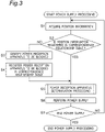
- FIG. 3 is a flowchart of operations associated with the power supply processing.
- the position information acquisition unit 10b acquires position information (which can be regarded as second position information indicating a second position of the obstruction 2) from the obstruction position detection apparatus 11.
- the position information indicates the position of the obstruction 2 detected by the obstruction position detection apparatus 11.
- the processor 10c determines whether the position identified by the position information acquired at step S1 (hereinafter referred to as the position acquired at step S1) is registered in the correspondence relationship table D1, which is stored in the memory 10d.
- FIG. 4 is an illustration of an example of the correspondence relationship table D1, which is stored in the memory 10d.
- the correspondence relationship table D1 is created in advance by a user before the power supply processing operation is started, for example.
- the position of the moving obstruction 2 is corelated to the identifier of the power reception apparatus 1 corresponding to the position.
- the position of the obstruction 2 is correlated to the identifier of the power reception apparatus 1 blocked by the obstruction 2 existing at the position.
- the wireless power supply from the power supply apparatus 10 to the power reception apparatus 1 identified by an identifier ID2 is blocked by the obstruction 2 existing at the position A.
- the wireless power supply from the power supply apparatus 10 to the power reception apparatus 1 identified by an identifier ID3 is interrupted by the obstruction 2 existing at the position E.
- step S2 illustrated in FIG. 3 it is assumed that the processor 10c determines that the position acquired at step S1 is not registered in the correspondence relationship table D1 (NO at step S2). For example, when the position acquired at step S1 is a position K, the position K is not registered in the correspondence relationship table D1 illustrated in FIG. 4 . In this case, the power supply apparatus 10 notifies that the position acquired at step S1 is not included in the correspondence relationship table D1.
- the user who recognizes the flow of NO (the above-described notification) at step S2 identifies the power reception apparatus 1 that is prevented from receiving power supplied from the power supply apparatus 10 when the obstruction 2 exists at the position acquired at step S1 (step S3). Then, the user registers, in the correspondence relationship table D1, which is stored in the memory 10d, the unregistered position acquired at step S1 and the identifier of the power reception apparatus 1 identified at step S3 and corresponding to the unregistered position (step S4). After step S4, the processor 10c starts the power reception apparatus determination processing at step S5.
- the processor 10c determines that the position acquired at step S1 is registered in the correspondence relationship table D1 (YES at step S2). For example, when the position acquired at step S1 is a position B, the position B is registered in the correspondence relationship table D1 illustrated in FIG. 4 . In this case, the processor 10c starts the power reception apparatus determination processing at step S5.
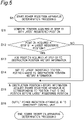
- FIG. 5 is a flowchart of a flow of a specific operations performed by the processor 10c in the power reception apparatus determination processing at step S5.
- the power reception apparatus determination processing will be described below with reference to FIG. 5 .
- the power reception apparatus determination unit 10c of the processor 10c4 compares the position acquired at step S1 with a "latest registered position", which is included in the obstruction movement history information table (hereinafter simply referred to as history information table) D2.
- the history information table D2 is stored in the memory 10d.
- FIG. 6 is an illustration of the history information table D2, which is stored in the memory 10d.
- the history information table D2 is array data in which pieces of the position information acquired by the position information acquisition unit 10b are arranged in time series.
- the history information table D2 exemplified in FIG. 6 indicates that the position information acquisition unit 10b has acquired the position information indicating the position B, the position information indicating a position C, and the position information indicating a position D in this order (time series).
- the position information acquisition unit 10b continuously receives position information indicating the same position a plurality of times, only the first position information, among the plurality of pieces of continuous information indicating the same position, is registered in the history information table D2.
- the position indicated by the position information registered last in time series is the above-described latest registered position.
- the latest registered position is the position D.
- step S12 illustrated in FIG. 5 as a result of the comparison at step S11, the power reception apparatus determination unit 10c4 determines whether the position acquired at step S1 is different from the latest registered position included in the history information table D2.
- step S12 it is assumed that the power reception apparatus determination unit 10c4 determines that the position acquired at step S1 is different from the latest registered position included in the history information table D2 (YES at step S12). For example, it is assumed that the position acquired at step S1 is the position E, and that the latest registered position included in the history information table D2 is the position D, as illustrated in FIG. 6 .
- the power reception apparatus determination unit 10c4 additionally registers, in accordance with the time-series order, the position information acquired at step S1 in the history information table D2, which is stored in the memory 10d.
- FIG. 7 illustrates a state in which position information indicating the position E is registered in the history information table D2, which is stored in the memory 10d, in the above-described example.
- step S14 the power reception apparatus determination unit 10c4 newly sets the position indicated by the position information added at step S13 as the latest registered position.
- the latest registered position included in the history information table D2 is the position E.
- the power reception apparatus determination unit 10c4 proceeds to the processing at step S15, which will be described later.
- step S12 it is assumed that the power reception apparatus determination unit 10c4 determines that the position acquired at step S1 and the latest registered position included in the history information table D2 are the same (NO at step S12). For example, it is assumed that the position acquired at step S1 is the position D and the latest registered position included in the history information table D2 is the position D, as illustrated in FIG. 6 . In this case, the power reception apparatus determination unit 10c4 proceeds to the processing at step S15.
- the history information table D2 is updated as follows.
- the position identified by the position information located at the end of the history information table D2 in time series is different from the position identified by the position information acquired at step S1
- the position information acquired at step S1 is added to the end of the history information table D2.
- the position identified by the position information located at the end of the history information table D2 in time series is the same as the position identified by the position information acquired at step S1
- the position information acquired at step S1 is not added to the end of the history information table D2.
- the acquired position information is not necessarily added to the end of the history information table D2.
- the position information acquisition unit 10b acquires position information different from the position information at the end of the history information table D2
- the acquired position information is added to the end of the history information table D2. It is to be noted that the position identified by the position information located at the end of the history information table D2 is the above-described latest registered position.
- the power reception apparatus determination unit 10c4 refers to the history information table D2, which is stored in the memory 10d. Then, the power reception apparatus determination unit 10c4 acquires position information (referred to as immediately preceding position information) that is one position before (immediately before) the latest registered position in time series in the history information D2.
- position information referred to as immediately preceding position information
- the immediately preceding position information previously received by the position information acquisition unit 10b is first position information indicating a first position of the obstruction 2.
- the position information received by the position information acquisition unit 10b at the present time is second position information indicating a second position that is after the obstruction 2 has moved from the first position.
- the first position is different from the second position.
- the power reception apparatus determination unit 10c4 determines a position (the above-described first position) identified by the immediately preceding position information (the above-described first position information). For example, in the example illustrated in FIG. 6 , the latest registered position is the position D, and the position identified by the immediately preceding position information is the position C. In the example illustrated in FIG. 7 , the latest registered position is the position E, and the position identified by the immediately preceding position information is the position D.
- the power reception apparatus determination unit 10c4 determines the power-supply-target power reception apparatus 1 using the immediately preceding position information and the correspondence relationship table D1, which is stored in the memory 10d. Specifically, the power reception apparatus determination unit 10c4 refers to the correspondence relationship table D1. Then, by this reference, the power reception apparatus determination unit 10c4 determines the identifier of the power reception apparatus 1 corresponding to the position identified by the immediately preceding position information. Then, the power reception apparatus determination unit 10c4 determines, as the power-supply-target power reception apparatus 1, the power reception apparatus 1 identified by the acquired identifier.
- the power reception apparatus determination unit 10c4 acquires an identifier ID4 of the power reception apparatus 1 corresponding to the position C in the correspondence relationship table D1 illustrated in FIG. 4 . Then, the power reception apparatus determination unit 10c4 determines, as the power-supply-target power reception apparatus 1, the power reception apparatus 1 identified by the identifier ID4.
- the power reception apparatus determination unit 10c4 acquires an identifier ID1 of the power reception apparatus 1 corresponding to the position D in the correspondence relationship table D1 exemplified in FIG. 4 . Then, the power reception apparatus determination unit 10c4 determines, as the power-supply-target power reception apparatus 1, the power reception apparatus 1 identified by the identifier ID1.
- the power reception apparatus determination unit 10c4 outputs, to the directivity control unit 10f, information including the identifier of the power-supply-target power reception apparatus 1 determined at step S15.
- the power reception apparatus determination unit 10c4 controls the directivity control unit 10f to steer a radio wave to the power-supply-target power reception apparatus 1 determined in step S15.
- the power reception apparatus determination processing at step S5 illustrated in FIG. 3 ends, and then the processing at step S6 illustrated in FIG. 3 is performed.
- the directivity control unit 10f controls the directivity of the power supply antenna 10c4 based on the control from the power reception apparatus determination unit 10a.
- the directivity control unit 10f supplies the radio wave generated by the power supply signal generation unit 10e to the power supply antenna 10a.
- the power supply antenna 10a is able to emit power toward the power-supply-target power reception apparatus 1 determined at step S15 illustrated in FIG. 5 .
- the power emitted to the power-supply-target power reception apparatus 1 is not blocked by the obstruction 2.
- step S7 the overall control unit 10cl determines whether a scheduled series of power supply processings has ended.
- the procedure returns to the processing at step 1.
- the power supply apparatus 10 ends the power supply processing illustrated in FIG. 3 .
- the power supply apparatus 10 includes the power supply antenna 10a, the directivity control unit 10f, the position information acquisition unit 10b, and the processor 10c.
- the power supply antenna 10a emits, to each of the plurality of power reception apparatuses 1, a radio wave that is based on a power supply signal.
- the directivity control unit controls the directivity of the power supply antenna 10a.
- the position information acquisition unit 10b acquires position information indicating the position of the obstruction 2 moving between the power supply antenna 10a and the power reception apparatus 1.
- the processor 10c determines a power-supply-target power reception apparatus 1, among the plurality of power reception apparatuses 1, to which power is to be supplied while avoiding the obstruction 2. Further, the processor 10c (power reception apparatus determination unit 10c4) controls the directivity control unit 10f to steer a radio wave to this power-supply-target power reception apparatus 1.
- the power supply apparatus 10 acquires position information indicating the position of the obstruction 2 at each power supply timing, thereby determining a power-supply-target power reception apparatus 1, among the plurality of power reception apparatuses 1, that is capable of receiving a radio wave without blockage by the obstruction 2.
- the power supply apparatus 10 is capable of dynamically controlling the directivity of the power supply antenna 10a by continuously acquiring position information indicating the position of the moving obstruction 2. This prevents interruption of the wireless power supply processing performed between the power supply apparatus 10 and the plurality of power reception apparatuses 1, regardless of the presence of the moving obstruction 2. In other words, even if there is a moving obstruction 2 that may interfere with power supply, efficient power supply processing is performed between the power supply apparatus 10 and the plurality of power reception apparatuses 1 without wireless power supply being interrupted by the obstruction 2.
- FIG. 8 For example, assume a case where the power supply apparatus 10 emits a radio wave to each power reception apparatus 1 without the position of the moving obstruction 2 taken into consideration. In this case, a problem as illustrated in FIG. 8 may occur. Specifically, as illustrated in FIG. 8 , there may be a problem in that radio waves emitted from the power supply apparatus 10 to the power reception apparatuses 1 are continuously blocked by the moving obstruction 2.
- the example illustrated in FIG. 8 can be understood as a least efficient example in terms of power supply.
- the power supply apparatus 10 is capable of, based on position information indicating the position of the moving obstruction 2, continuously changing the directivity of a radio wave emitted from the power supply apparatus 10, as described above.
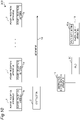
- FIG. 9 exemplifies a state in which using position information indicating the position of the moving obstruction 2, the power supply apparatus 10 dynamically controls the directivity of radio waves emitted from the power supply antenna 10a while avoiding the obstruction 2.
- FIG. 9 illustrates an example of the correspondence relationship table D1, which is stored in the memory 10d, and examples of the history information table D2 stored in the memory 10d at the end of step S5 in FIG. 3 and corresponding to time t1 to t4.
- the power supply apparatus 10 when the power supply apparatus 10 according to the present embodiment is not employed, it is necessary to, for example, determine and/or change the installation locations of the power reception apparatuses 1 and the power supply apparatus 10 in consideration of movement or the like of the obstruction 2, which is an obstruction element for radio waves.
- the number of power reception apparatuses 1 increases, the degree of freedom of their installation locations is limited, and it may be difficult to find appropriate installation locations.
- the directivity of the power supply antenna 10a is dynamically controlled based on position information indicating the position of the moving obstruction 2, as described above. This ensures that the installation of, for example, the power reception apparatuses 1 is easily determined.
- the power supply apparatus 10 further includes the memory 10d, which stores the correspondence relationship table D1.
- the position information acquisition unit 10b acquires position information indicating the current position of the obstruction 2 after movement.
- the processor 10c refers to the correspondence relationship table D1 and determines the identifier of the power-supply-target power reception apparatus 1 corresponding to the position identified by the immediately preceding position information (step S15 illustrated in FIG. 5 ).
- the processor 10c controls the directivity control unit 10f to steer a radio wave to this power suppliable power reception apparatus 1 (step S16 in FIG. 5 ).
- the power supply apparatus 10 is capable of automatically determining the power-supply-target power reception apparatus 1 based on the current position information, acquisition history of the past position information (history information table D2), and the correspondence relationship table D1. Accordingly, even if there is a change in the movement pattern of the obstruction 2, the power-supply-target power reception apparatus 1 is automatically determined without blockage by the obstruction 2.
- the position information acquisition unit 10b acquires position information transmitted from the obstruction position detection apparatus 11, which detects the position of the obstruction 2.
- the power supply apparatus 10 is capable of controlling the directivity of the power supply antenna 10a in consideration of the actual position of the moving obstruction 2.
- the position information acquisition unit 10b acquires the position information transmitted from the obstruction position detection apparatus 11.
- the position information acquisition unit 10b may acquire position information indicating the position of the obstruction 2 by any other method.
- FIG. 10 illustrates an example of a configuration of a power supply system 200 according to another embodiment.
- a programmable logic control unit (PLC) 20 is connected to the power supply apparatus 10. More specifically, in the configuration example illustrated in FIG. 10 , the PLC 20 is connected to and between the obstruction position detection apparatus 11 and the power supply apparatus 10. It is to be noted that the connection between the PLC 20 and the power supply apparatus 10 may be a wireless communication connection or a wired communication connection.
- the PLC 20 is an obstruction control apparatus that controls the movement of the obstruction 2 in accordance with a control flow set in the PLC 20.
- control information indicating how to move the obstruction 2 in terms of time is defined.
- the PLC 20 refers to the control information of the control flow (based on the control of the obstruction 2 by the PLC 20), and identifies the position of the obstruction 2 at a certain point of time. Then, the PLC 20 identifies the position as time passes, and continuously transmits position information indicating the identified position to the position information acquisition unit 10b.
- the power supply apparatus 10 position information acquisition unit 10b acquires the position information transmitted from the PLC 20, which controls the movement of the obstruction 2. It is to be noted that although the transmission source of the position information is different between the power supply system 100 and the power supply system 200, the other configurations and the operations described with reference to FIGs. 3 and 5 are the same between the power supply system 100 and the power supply system 200.
- the power supply apparatus 10 illustrated in FIG. 10 is capable of, without detecting the actual position of the obstruction 2, dynamically controlling the directivity of the power supply antenna 10a using the position information of the obstruction 2 included in the control flow of the PLC 20.
- the position information acquisition unit 10b is capable of acquiring position information not only from the PLC 20 but also from the obstruction position detection apparatus 11 (for example, via the PLC 20 or not via the PLC 20).
- the obstruction position detection apparatus 11 may be omitted.
Landscapes
- Engineering & Computer Science (AREA)
- Computer Networks & Wireless Communication (AREA)
- Power Engineering (AREA)
- Charge And Discharge Circuits For Batteries Or The Like (AREA)
- Radar Systems Or Details Thereof (AREA)
- Position Fixing By Use Of Radio Waves (AREA)
Applications Claiming Priority (1)
| Application Number | Priority Date | Filing Date | Title |
|---|---|---|---|
| PCT/JP2019/028473 WO2021014496A1 (fr) | 2019-07-19 | 2019-07-19 | Appareil d'alimentation électrique et système d'alimentation électrique |
Publications (2)
| Publication Number | Publication Date |
|---|---|
| EP4002645A1 true EP4002645A1 (fr) | 2022-05-25 |
| EP4002645A4 EP4002645A4 (fr) | 2023-04-26 |
Family
ID=74193748
Family Applications (1)
| Application Number | Title | Priority Date | Filing Date |
|---|---|---|---|
| EP19938843.0A Pending EP4002645A4 (fr) | 2019-07-19 | 2019-07-19 | Appareil d'alimentation électrique et système d'alimentation électrique |
Country Status (5)
| Country | Link |
|---|---|
| US (1) | US11967835B2 (fr) |
| EP (1) | EP4002645A4 (fr) |
| JP (1) | JP7173349B2 (fr) |
| CN (1) | CN114041257B (fr) |
| WO (1) | WO2021014496A1 (fr) |
Family Cites Families (27)
| Publication number | Priority date | Publication date | Assignee | Title |
|---|---|---|---|---|
| JP4318044B2 (ja) * | 2005-03-03 | 2009-08-19 | ソニー株式会社 | 電力供給システム、電力供給装置および方法、受電装置および方法、記録媒体、並びにプログラム |
| US8469122B2 (en) * | 2005-05-24 | 2013-06-25 | Rearden, Llc | System and method for powering vehicle using radio frequency signals and feedback |
| JP4982598B2 (ja) * | 2010-09-07 | 2012-07-25 | 株式会社東芝 | 無線電力伝送システム、該システムの送電装置および受電装置 |
| KR20130035905A (ko) * | 2011-09-30 | 2013-04-09 | 삼성전자주식회사 | 무선 충전 장치 및 방법 |
| US10270261B2 (en) * | 2015-09-16 | 2019-04-23 | Energous Corporation | Systems and methods of object detection in wireless power charging systems |
| US9948135B2 (en) * | 2015-09-22 | 2018-04-17 | Energous Corporation | Systems and methods for identifying sensitive objects in a wireless charging transmission field |
| JP6108915B2 (ja) * | 2013-04-02 | 2017-04-05 | キヤノン株式会社 | 受電装置、その制御方法およびプログラム |
| JP6258816B2 (ja) * | 2013-10-29 | 2018-01-10 | パナソニック株式会社 | 無線送電装置及び無線電力伝送システム |
| JP6366292B2 (ja) * | 2014-02-10 | 2018-08-01 | キヤノン株式会社 | 電子機器、制御方法及びプログラム |
| JP6337797B2 (ja) * | 2015-02-13 | 2018-06-06 | オムロン株式会社 | 無線給電制御システム、無線給電制御装置、無線給電制御方法、及び指向性情報生成方法 |
| US9971015B2 (en) | 2015-04-10 | 2018-05-15 | Ossia Inc. | Techniques for imaging wireless power delivery environments and tracking objects therein |
| US9673665B2 (en) * | 2015-06-30 | 2017-06-06 | Ossia Inc. | Energy delivery modulation in wireless power delivery environments |
| US11710321B2 (en) * | 2015-09-16 | 2023-07-25 | Energous Corporation | Systems and methods of object detection in wireless power charging systems |
| EP3395101B1 (fr) * | 2015-12-24 | 2021-04-07 | Energous Corporation | Systèmes et procédés de détection d'objet dans des systèmes de recharge sans fil |
| KR20180039880A (ko) * | 2016-10-11 | 2018-04-19 | 주식회사 위스텍 | 전파 경로의 조절이 가능한 무선 충전 시스템 |
| US9991752B1 (en) * | 2016-12-07 | 2018-06-05 | Panasonic Corporation | Wireless power feeding method |
| JP6886295B2 (ja) * | 2017-01-13 | 2021-06-16 | キヤノン株式会社 | 給電装置、制御装置およびそれらの制御方法、並びにプログラム |
| JP6551755B2 (ja) * | 2017-02-09 | 2019-07-31 | パナソニックIpマネジメント株式会社 | 無線電力伝送システムにおける送電装置の制御方法、および送電装置 |
| JP6918544B2 (ja) * | 2017-03-28 | 2021-08-11 | キヤノン株式会社 | 給電装置およびその制御方法、並びにプログラム |
| JP6967867B2 (ja) * | 2017-04-04 | 2021-11-17 | キヤノン株式会社 | 送電装置およびその制御方法、並びにプログラム |
| KR102423176B1 (ko) * | 2017-08-21 | 2022-07-21 | 한국전자통신연구원 | 무선 전력 전송 장치 및 무선 전력 전송 방법 |
| KR102029919B1 (ko) * | 2017-09-11 | 2019-10-08 | 전자부품연구원 | 지능형 무선전력 전송장치, 지능형 무선전력을 이용한 충전 시스템 및 지능형 무선전력 제공방법 |
| JP6970063B2 (ja) * | 2018-08-20 | 2021-11-24 | 株式会社東芝 | 電子装置、測定装置及び方法 |
| JP6852028B2 (ja) * | 2018-09-04 | 2021-03-31 | 株式会社東芝 | 電子装置及び方法 |
| US10839179B2 (en) * | 2018-10-17 | 2020-11-17 | Vubiq Networks, Inc. | Multimode millimeter wave RFID devices and methods of use thereof |
| WO2020183722A1 (fr) * | 2019-03-14 | 2020-09-17 | オムロン株式会社 | Dispositif de transmission de puissance sans fil et système de transmission de puissance sans fil |
| JP7259970B2 (ja) * | 2019-08-19 | 2023-04-18 | オムロン株式会社 | 無線電力伝送システム |
-
2019
- 2019-07-19 WO PCT/JP2019/028473 patent/WO2021014496A1/fr not_active Ceased
- 2019-07-19 US US17/621,316 patent/US11967835B2/en active Active
- 2019-07-19 CN CN201980098112.6A patent/CN114041257B/zh active Active
- 2019-07-19 EP EP19938843.0A patent/EP4002645A4/fr active Pending
- 2019-07-19 JP JP2021534857A patent/JP7173349B2/ja active Active
Also Published As
| Publication number | Publication date |
|---|---|
| CN114041257A (zh) | 2022-02-11 |
| US20220360114A1 (en) | 2022-11-10 |
| EP4002645A4 (fr) | 2023-04-26 |
| US11967835B2 (en) | 2024-04-23 |
| WO2021014496A1 (fr) | 2021-01-28 |
| JPWO2021014496A1 (fr) | 2021-01-28 |
| CN114041257B (zh) | 2025-04-11 |
| JP7173349B2 (ja) | 2022-11-16 |
Similar Documents
| Publication | Publication Date | Title |
|---|---|---|
| US10770925B2 (en) | Electronic apparatus and method | |
| EP3481117B1 (fr) | Système sans fil point à point, dispositif sans fil point à point, et procédé de commande de communication | |
| JP6950632B2 (ja) | 無線で電力を供給する送電装置及び異物検出方法 | |
| US20230047897A1 (en) | Occupancy detection apparatus using multiple antenna motion sensing | |
| EP3896600A1 (fr) | Atténuation des interférences des lecteurs rfid adjacents | |
| JP2020005468A (ja) | 無線給電装置及び無線給電方法 | |
| US10555057B2 (en) | Wireless sensor system, communication device, sensor tag, and communication method | |
| US20150171977A1 (en) | Electronic apparatus and processing method of an electronic apparatus | |
| JP2020005469A5 (fr) | ||
| JP2011205579A (ja) | データ収集システムおよび無線タグ | |
| US20200057474A1 (en) | Electronic apparatus, measurement apparatus, and method | |
| US11967835B2 (en) | Power supply apparatus and power supply system | |
| EP2472437A2 (fr) | Système d'identification de fréquence radio | |
| JP2017527783A (ja) | 医療装置システム、ならびに医療装置システムの医療装置およびモバイル制御ユニットを探知する方法 | |
| US10146970B2 (en) | RFID reader | |
| US11194036B2 (en) | Systems and methods for automatic motion detection | |
| KR102136677B1 (ko) | 카메라를 이용한 무선 전력 송신장치 및 그 제어방법 | |
| KR20140112319A (ko) | 자동 정합 회로를 근거로 한 rfid 리더 및 그의 제어 방법 | |
| JP2019219354A (ja) | 接近検知システム | |
| US20240235264A1 (en) | Wireless power supply system, power transmitter, power receiver, and wireless power supply system control method | |
| EP3907711A1 (fr) | Composant de système d'alarme configurable | |
| US20160241047A1 (en) | Power receiving apparatus, power transmitting apparatus, control method, and storage medium | |
| EP2674790A1 (fr) | Dispositif, system et procédé de détection d'objets métalliques | |
| KR20150104335A (ko) | 레이더 모듈을 갖는 감시 장치 | |
| US20080198908A1 (en) | Transceiver |
Legal Events
| Date | Code | Title | Description |
|---|---|---|---|
| STAA | Information on the status of an ep patent application or granted ep patent |
Free format text: STATUS: THE INTERNATIONAL PUBLICATION HAS BEEN MADE |
|
| PUAI | Public reference made under article 153(3) epc to a published international application that has entered the european phase |
Free format text: ORIGINAL CODE: 0009012 |
|
| STAA | Information on the status of an ep patent application or granted ep patent |
Free format text: STATUS: REQUEST FOR EXAMINATION WAS MADE |
|
| 17P | Request for examination filed |
Effective date: 20211220 |
|
| AK | Designated contracting states |
Kind code of ref document: A1 Designated state(s): AL AT BE BG CH CY CZ DE DK EE ES FI FR GB GR HR HU IE IS IT LI LT LU LV MC MK MT NL NO PL PT RO RS SE SI SK SM TR |
|
| DAV | Request for validation of the european patent (deleted) | ||
| DAX | Request for extension of the european patent (deleted) | ||
| REG | Reference to a national code |
Ref country code: DE Ref legal event code: R079 Free format text: PREVIOUS MAIN CLASS: H02J0050230000 Ipc: H02J0050400000 |
|
| A4 | Supplementary search report drawn up and despatched |
Effective date: 20230324 |
|
| RIC1 | Information provided on ipc code assigned before grant |
Ipc: H02J 50/20 20160101ALI20230320BHEP Ipc: H02J 50/60 20160101ALI20230320BHEP Ipc: H02J 50/80 20160101ALI20230320BHEP Ipc: H02J 50/90 20160101ALI20230320BHEP Ipc: H02J 50/40 20160101AFI20230320BHEP |
|
| GRAP | Despatch of communication of intention to grant a patent |
Free format text: ORIGINAL CODE: EPIDOSNIGR1 |
|
| STAA | Information on the status of an ep patent application or granted ep patent |
Free format text: STATUS: GRANT OF PATENT IS INTENDED |
|
| INTG | Intention to grant announced |
Effective date: 20260703 |