EP4002660A1 - Unité de mesure de courant et dispositif de conversion de puissance - Google Patents
Unité de mesure de courant et dispositif de conversion de puissance Download PDFInfo
- Publication number
- EP4002660A1 EP4002660A1 EP20844881.1A EP20844881A EP4002660A1 EP 4002660 A1 EP4002660 A1 EP 4002660A1 EP 20844881 A EP20844881 A EP 20844881A EP 4002660 A1 EP4002660 A1 EP 4002660A1
- Authority
- EP
- European Patent Office
- Prior art keywords
- current
- turn
- measurement unit
- power module
- time
- Prior art date
- Legal status (The legal status is an assumption and is not a legal conclusion. Google has not performed a legal analysis and makes no representation as to the accuracy of the status listed.)
- Pending
Links
- 238000005259 measurement Methods 0.000 title claims abstract description 66
- 238000006243 chemical reaction Methods 0.000 title claims abstract description 59
- 238000004364 calculation method Methods 0.000 claims abstract description 87
- 238000010992 reflux Methods 0.000 claims description 14
- 238000010586 diagram Methods 0.000 description 36
- 238000000034 method Methods 0.000 description 11
- 238000000691 measurement method Methods 0.000 description 10
- 238000005516 engineering process Methods 0.000 description 6
- 230000006870 function Effects 0.000 description 3
- 230000001939 inductive effect Effects 0.000 description 3
- 230000000694 effects Effects 0.000 description 2
- 238000009529 body temperature measurement Methods 0.000 description 1
- 239000003990 capacitor Substances 0.000 description 1
- 238000012937 correction Methods 0.000 description 1
- 238000012217 deletion Methods 0.000 description 1
- 230000037430 deletion Effects 0.000 description 1
- 238000007599 discharging Methods 0.000 description 1
- 230000009977 dual effect Effects 0.000 description 1
- 238000009499 grossing Methods 0.000 description 1
- 230000001771 impaired effect Effects 0.000 description 1
- 230000006698 induction Effects 0.000 description 1
- 238000012986 modification Methods 0.000 description 1
- 230000004048 modification Effects 0.000 description 1
- 230000004044 response Effects 0.000 description 1
- 239000004065 semiconductor Substances 0.000 description 1
- 230000001360 synchronised effect Effects 0.000 description 1
- 238000004804 winding Methods 0.000 description 1
Images






Classifications
-
- H—ELECTRICITY
- H02—GENERATION; CONVERSION OR DISTRIBUTION OF ELECTRIC POWER
- H02M—APPARATUS FOR CONVERSION BETWEEN AC AND AC, BETWEEN AC AND DC, OR BETWEEN DC AND DC, AND FOR USE WITH MAINS OR SIMILAR POWER SUPPLY SYSTEMS; CONVERSION OF DC OR AC INPUT POWER INTO SURGE OUTPUT POWER; CONTROL OR REGULATION THEREOF
- H02M7/00—Conversion of AC power input into DC power output; Conversion of DC power input into AC power output
- H02M7/42—Conversion of DC power input into AC power output without possibility of reversal
- H02M7/44—Conversion of DC power input into AC power output without possibility of reversal by static converters
- H02M7/48—Conversion of DC power input into AC power output without possibility of reversal by static converters using discharge tubes with control electrode or semiconductor devices with control electrode
- H02M7/53—Conversion of DC power input into AC power output without possibility of reversal by static converters using discharge tubes with control electrode or semiconductor devices with control electrode using devices of a triode or transistor type requiring continuous application of a control signal
- H02M7/537—Conversion of DC power input into AC power output without possibility of reversal by static converters using discharge tubes with control electrode or semiconductor devices with control electrode using devices of a triode or transistor type requiring continuous application of a control signal using semiconductor devices only, e.g. single switched pulse inverters
- H02M7/5387—Conversion of DC power input into AC power output without possibility of reversal by static converters using discharge tubes with control electrode or semiconductor devices with control electrode using devices of a triode or transistor type requiring continuous application of a control signal using semiconductor devices only, e.g. single switched pulse inverters in a bridge configuration
- H02M7/53871—Conversion of DC power input into AC power output without possibility of reversal by static converters using discharge tubes with control electrode or semiconductor devices with control electrode using devices of a triode or transistor type requiring continuous application of a control signal using semiconductor devices only, e.g. single switched pulse inverters in a bridge configuration with automatic control of output voltage or current
-
- H—ELECTRICITY
- H02—GENERATION; CONVERSION OR DISTRIBUTION OF ELECTRIC POWER
- H02M—APPARATUS FOR CONVERSION BETWEEN AC AND AC, BETWEEN AC AND DC, OR BETWEEN DC AND DC, AND FOR USE WITH MAINS OR SIMILAR POWER SUPPLY SYSTEMS; CONVERSION OF DC OR AC INPUT POWER INTO SURGE OUTPUT POWER; CONTROL OR REGULATION THEREOF
- H02M1/00—Details of apparatus for conversion
- H02M1/0003—Details of control, feedback or regulation circuits
- H02M1/0009—Devices or circuits for detecting current in a converter
-
- H—ELECTRICITY
- H02—GENERATION; CONVERSION OR DISTRIBUTION OF ELECTRIC POWER
- H02M—APPARATUS FOR CONVERSION BETWEEN AC AND AC, BETWEEN AC AND DC, OR BETWEEN DC AND DC, AND FOR USE WITH MAINS OR SIMILAR POWER SUPPLY SYSTEMS; CONVERSION OF DC OR AC INPUT POWER INTO SURGE OUTPUT POWER; CONTROL OR REGULATION THEREOF
- H02M1/00—Details of apparatus for conversion
- H02M1/32—Means for protecting converters other than automatic disconnection
- H02M1/327—Means for protecting converters other than automatic disconnection against abnormal temperatures
-
- H—ELECTRICITY
- H02—GENERATION; CONVERSION OR DISTRIBUTION OF ELECTRIC POWER
- H02P—CONTROL OR REGULATION OF ELECTRIC MOTORS, ELECTRIC GENERATORS OR DYNAMO-ELECTRIC CONVERTERS; CONTROLLING TRANSFORMERS, REACTORS OR CHOKE COILS
- H02P23/00—Arrangements or methods for the control of AC motors characterised by a control method other than vector control
- H02P23/14—Estimation or adaptation of motor parameters, e.g. rotor time constant, flux, speed, current or voltage
-
- H—ELECTRICITY
- H02—GENERATION; CONVERSION OR DISTRIBUTION OF ELECTRIC POWER
- H02P—CONTROL OR REGULATION OF ELECTRIC MOTORS, ELECTRIC GENERATORS OR DYNAMO-ELECTRIC CONVERTERS; CONTROLLING TRANSFORMERS, REACTORS OR CHOKE COILS
- H02P29/00—Arrangements for regulating or controlling electric motors, appropriate for both AC and DC motors
- H02P29/60—Controlling or determining the temperature of the motor or of the drive
- H02P29/68—Controlling or determining the temperature of the motor or of the drive based on the temperature of a drive component or a semiconductor component
Definitions
- the present invention relates to the configuration of a current measurement unit, and particularly to a technology effective when applied to a power conversion device for automobiles and railways, which requires miniaturization and low power loss.
- an inverter which is a power conversion device and a motor control unit are provided between a DC power supply and the motor, and a load current being a drive signal is sent to the motor by the inverter to drive the motor.
- the inverter converts DC power output from the DC power supply into an AC signal determined according to a torque command value, and sends the load current to the motor.
- An inverter control unit sends a control signal for generating a load current to the inverter to control the inverter.
- the control signal is determined based on the AC signal determined based on the torque command value and an AC signal generated based on current motor position information and a load current value.
- Patent Literature 1 As a measurement technology related to an inverter, for example, there is known such technology as described in Patent Literature 1. There has been disclosed in Patent Literature 1 "a technology for measuring the temperature of a power module in order to monitor whether the junction temperature of the power module inside an inverter is working so as not to exceed a safe operating region".
- the miniaturization of the power conversion device has been required to improve the degree of freedom in designing the motor drive system.
- a method of miniaturizing the power conversion device there is known a technology of omitting a current sensor that measures the load current between the inverter and the motor. The load current is measured by installing a load current sensor inside the inverter.
- Patent Literature 2 a technology of measuring a load current by a shunt resistor installed in a power supply line.
- the load current measuring method provided with the shunt resistor such as shown in Patent Literature 2 is accompanied by a problem that a space for installing the shunt resistor is required, and also the energy saving property of the inverter is impaired because a power loss due to the shunt resistor occurs.
- an object of the present invention is to provide a current measurement unit capable of measuring a load current without providing a current sensor between an inverter and a load or inside the inverter, and capable of miniaturization, and a power conversion device using the current measurement unit.
- the present invention provides a current measurement unit which measures a load current supplied from a power conversion device to a load, and includes a power module which controls energization of the power conversion device, a control unit which controls the power module, a turn-off time measuring unit which measures a turn-off time of the power module, an information measurement unit which measures at least either of temperature information of the power module and a DC power supply voltage input to the power module and outputs a result of the measurement, and a current calculation unit which calculates the load current, based on the output of the turn-off time measuring unit and the output of the information measurement unit.
- the present invention provides a power conversion device having the above-mentioned current measurement unit, and the load is a motor driven by the power conversion device.
- a current measurement unit capable of measuring a load current without providing a current sensor between the inverter and a load or inside the inverter, and capable of miniaturization, and a power conversion device using the current measurement unit.
- a power conversion device is used by being mounted on, for example, an electric vehicle such as for a railway, a hybrid vehicle, or an electric car.
- an electric vehicle such as for a railway, a hybrid vehicle, or an electric car.
- a rotary electric machine driven by a power converter is a three-phase AC motor for railways, but a rotary electric machine such as a motor other than for railways can also be used.
- the rotary electric machine is a motor having the function of only the motor, it can be a motor generator having both the functions of a motor and a generator, or one having the function of only a generator.
- the number of phases of the rotary electric machine may be other than three.
- the control of the rotary electric machine will be described assuming that the drive current of the rotary electric machine is fed back to a current value command value.
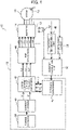
- FIG. 1 is a block diagram showing the power conversion device according to the present embodiment. This device is intended to drive a three-phase induction motor.
- Fig. 1 shows a motor 16 which is a rotary electric machine to be driven by a power converter, an inverter 14 which is a power converter, and a motor control unit 18 which controls the inverter 14.
- the power conversion device 10 includes a DC power supply device 12 which supplies DC power, a voltage sensor (DC power supply voltage value measuring unit) 52 which measures a voltage value of the DC power supply device 12, an inverter 14 which converts the DC power from the DC power supply device 12 into AC power, a three-phase AC type motor 16 for railways driven by using an AC current (U-phase current ium, V-phase current ivm, W-phase current iwm) generated by the inverter 14, a motor control unit 18 which sends a control signal for driving the motor 16 to the inverter 14, i.e., controls the inverter 14, a temperature sensor 20, a motor position sensor (rotation angle sensor) 24, a turn-off time measuring unit 48, which is a turn-off delay time calculating unit for calculating a turn-off delay time of a power module (IGBT) mounted in the inverter 14, and a current calculation unit 50 which calculates a current value, based on the results of at least either one of the
- the temperature sensor 20 is, for example, a temperature sensor provided in a module, but it can also be a method or sensor for estimating the temperature of modules other than that.
- the motor 16 is, for example, a synchronous motor provided with a permanent magnet, but motors other than that can also be used.
- the motor control unit 18 includes a microcomputer having a CPU, a memory, and the like.
- the motor control unit 18 has a torque command calculation part 38, a current command calculation part 40, a current command/three-phase voltage conversion part 42, a PWM conversion part 44, and a feedback conversion part 46.
- the feedback conversion part 46 converts the motor drive currents ium, ivm, and iwm calculated by the current calculation unit 50 into a d-axis current id and a q-axis current iq by three-phase/two-phase conversion using a rotation angle ⁇ of the motor 16, and inputs the same to the current command/three-phase voltage conversion part 42.
- the current command calculation part 40 calculates a d-axis current command value id* and a q-axis current command value iq* being current command values based on an output torque command value input from the torque command calculation part 38 in accordance with a table or the like created in advance, and outputs the same to the current command/3-phase voltage conversion part 42.
- the current command/three-phase voltage conversion part 42 generates voltage command values for the d-axis and q-axis from the d-axis current command value id* and the q-axis current command value iq*, and the d-axis current id and the q-axis current iq input from the feedback conversion part 46, and then converts them into three-phase AC voltage command values Vu*, Vv*, and Vw* using the rotation angle ⁇ of the motor 16 and inputs the same to the PWM conversion part 44.
- the PWM conversion part 44 generates PWM control signals vuu, vud, vvu, vvd, vwu, and vwd to control turn ON/OFF of respective IGBTs 28 and 30 (to be described later in Fig. 2 ) constituting the inverter 14, based on the input three-phase AC voltage command values Vu*, Vv*, and Vw* and the DC power supply voltage, and inputs them to the inverter 14. Consequently, the inverter 14 outputs a drive signal to the motor 16 to drive the motor 16.
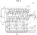
- Fig. 2 is a block diagram showing in detail the configuration of the inverter 14 shown in Fig. 1 .
- the inverter 14 is connected between the positive electrode side and the negative electrode side of the DC power supply device 12, converts input power from DC power to AC power, and outputs the power therefrom.
- the inverter 14 includes a plurality of IGBTs 28 and 30 which are a plurality of switching elements, and reflux diodes 32 each connected corresponding to each of the IGBTs 28 and 30.
- a gate voltage of each of the IGBTs 28 and 30 is controlled by a gate driver 55.
- the plurality of IGBTs 28 and 30 are connected to the windings of the three phases (U phase, V phase, W phase) of the motor 16, respectively. That is, three inverter arms consisting of series connections of two respective IGBTs 28 and 30 are received between the positive electrode side line 34 extending from the positive electrode of the DC power supply device 12 and the negative electrode side line 36 extending from the negative electrode side thereof. The midpoints of the two respective IGBTs 28 and 30 are connected to three-phase coils of the motor 16, respectively.
- the IGBT 28 provided on the positive electrode side is referred to as the upper IGBT 28, and the IGBT 30 provided on the lower arm on the negative electrode side is referred to as the lower IGBT 30.
- the upper IGBT 28 and the lower IGBT 30 are connected in series with each other. Then, the ON/OFF of the IGBTs 28 and 30 is controlled to supply AC power to the motor 16.
- a smoothing capacitor and a boost converter both not shown are connected between the motor 16 and the DC power supply device 12.
- the switching elements constituting the inverter 14 are not limited to the IGBTs 28 and 30, and various switching elements such as transistors and MOSFETs can be adopted.
- Fig. 3 is a diagram showing an example of a current value calculation map 39 stored in the current calculation unit 50 of Figs. 1 and 2 .
- the map of Fig. 3 may include at least one piece of information about either the power supply voltage value or the temperature.
- the map shows the relationship among at least either one of the temperature of each of the IGBTs 28 and 30 being the switching elements and the voltage value of the DC power supply of the inverter 14, a turn-off time of each of the IGBTs 28 and 30 being the switching elements, and an on-driving passing current value (conduction current value) of each of the IGBTs 28 and 30 being the switching elements.
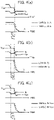
- Fig. 4(a) is a diagram showing an example of a time change in the element characteristic of the IGBT at the time of turn-off.
- Vge is a voltage between the gate and emitter of the IGBT
- Ig is a gate current of the IGBT
- Ic is a current between the collector and emitter of the IGBT.
- Switching of semiconductor elements including IGBTs performs turn-on/turn-off by charging/discharging a gate capacitance.
- Cgc which is the capacitance between the gate and collector changes due to the fluctuation of Vge, and a period during which Vge becomes flat occurs to charge and discharge Cgc. This period is called a "mirror period".
- VGP is Vge that becomes flat during the mirror period. Let this period be tm.
- the steady-state current value Ic drops from a solid line Ic to a chain line Ic
- Vge changes from a solid line Vge to a chain line Vge
- Ig changes from a solid line Ig to a chain line Ig, respectively.
- the tm period increases from tm1 to tm2.
- Fig. 4(b) is a diagram showing an example of a time change in the element characteristic when the temperature of the IGBT at the time of turn-off changes.
- Tj represents a junction temperature inside the power module. Temperature information does not have to be Tj, but may be one which reflects the temperature information related to the IGBT as in the case temperature of the power module. As Tj increases, the characteristics of Ic, Vge, and Ig change from a solid line to a chain line. At this time, the tm period increases from tm3 to tm4.
- Fig. 4(c) is a diagram showing an example of a time change in the element characteristic when the power supply voltage of the IGBT at the time of turn-off changes.
- Vcc is a DC power supply voltage value.
- the characteristics of Ic, Vge, and Ig change from a solid line to a chain line.
- the tm period increases from tm5 to tm6.
- Fig. 5(a) is a diagram showing an example of a Vge turn-off time td1000 obtained by extracting Vge of Fig. 4(a) .
- the turn-off time td1000 needs to be the time having the mirror period tm.
- Fig. 5(b) is a diagram showing an example of an Ig turn-off time td1001 obtained by extracting Ig of Fig. 4(a) .
- the turn-off time td1001 is the time having the mirror period tm.
- the turn-off time td in the present embodiment an example using the turn-off time td1001 of the gate current will be described, but the turn-off time td1000 of the gate voltage may be used.
- ⁇ s is a dielectric constant
- p0 is a hole concentration at the interface between a p layer of a collector region of the IGBT/conductivity modulation region
- Vcs is the power supply voltage
- Wn is a drift layer width of the IGBT
- Nd is a donor density of a drift layer
- psc is a hole density of a space charge region
- Jcon is a current density of Ic at the time of conduction.
- Fig. 7 is a diagram showing an example of the difference between the turn-off time of the gate current and the collector current at the time of turn-off of the IGBT used to obtain the map of Fig. 3 depending on the temperature. It can be seen that the higher the temperature, the longer the turn-off time even if the current value of Ic in the steady state is the same. This is because tm changes as the temperature changes.
- Fig. 8 is a diagram showing an example of the difference between the turn-off time of the gate current and the DC power supply voltage value at the time of turn-off of the IGBT used to obtain the map of Fig. 3 . It can be seen that when the power supply voltage value becomes large, the turn-off time becomes long even if the current value of Ic in the steady state is the same. This is because tm changes depending on the difference in the DC power supply voltage value.
- the current value calculation map 39 created in view of such points can calculate the conduction current values of the IGBTs 28 and 30 by referring to the terms of the turn-off time, the DC power supply voltage value, and the temperature.
- Fig. 9(a) is a diagram showing the relationship between an operating time and a turn-off time of the IGBT 28 being the upper arm.
- Fig. 9(b) is a diagram showing the relationship between an operating time and a turn-off time of the IGBT 30 being the lower arm.
- the conduction current values of the IGBTs 28 and 30 at the time of switching can be calculated based on the current value calculation map 39 stored in the current calculation unit 50.
- the load current value has a relation in which its positive value becomes equal to the conduction current value of the upper arm IGBT 28, and its negative value becomes equal to the conduction current value of the lower arm IGBT 30.
- Fig. 9(c) is a diagram showing with a solid line, an estimated motor current plotted by converting the turn-off time during switching in Figs. 9(a) and 9(b) into a conduction current value using the current value calculation map 39 stored in the current calculation unit 50, and in consideration of the positive/negative relationship between the upper and lower arms and the load current value, and values acquired from the current sensor installed in the inductive load.
- the current sensor installed in the inductive load (motor 16) is for verifying the accuracy of the current measurement method of the present embodiment, and is not illustrated in Figs. 1 and 2 .
- the current measurement method in the present embodiment is capable of measuring the inductive load current.
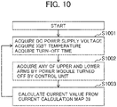
- Fig. 10 is a flowchart for measuring the load current created in view of these relationships.
- Step S1001 a DC power supply voltage is acquired by the voltage sensor 52, an IGBT temperature is acquired by the temperature sensor 20, and an IGBT turn-off time is acquired (calculated) by the turn-off time measuring unit 48.
- Step S1002 the power module (IGBT) which is turned OFF by the motor control unit 18 acquires and stores either the upper or lower arm.
- Step S1002 may be executed before Step S1001.
- Step S1003 the absolute value of the current value is determined from the current value calculation map 39, based on the turn-off time, the DC power supply voltage value, and the temperature of the IGBT acquired in Step S1001.
- the positive or negative of the current value is determined based on whether the power module (IGBT) which is turned OFF is either the upper or lower arm.
- the current value for one phase can be calculated from this flowchart (current measurement method). By carrying out the flow from Step S1001 to Step S1003 in three phases, all the load current values of the three phases can be measured.
- the current measurement unit of the present embodiment is a current measuring instrument that measures the load current supplied from the power conversion device 10 to the load (motor 16), and includes the power module (inverter 14) which controls the energization of the power conversion device 10, the control unit (motor control unit 18) which controls the power module (inverter 14), the turn-off time measuring unit 48 which measures the turn-off time of the power module (inverter 14), the information measurement unit (temperature sensor 20, voltage sensor 52) which measures at least either one of the temperature information of the power module (inverter 14) and the DC power supply voltage 12 input to the power module (inverter 14) and outputs the measurement result, and the current calculation unit 50 which calculates the load current, based on the output of the turn-off time measuring unit 48 and the output of the information measurement unit (temperature sensor 20, voltage sensor 52).
- the current calculation unit 50 has the preset current value calculation map 39, and calculates the load current, based on the output of the turn-off time measuring unit 48, the output of the information measurement unit (temperature sensor 20, voltage sensor 52), and the current value calculation map 39.
- the present embodiment it is possible to realize a current measurement unit that measures a load current, which combines small size and energy saving without installing a current sensor between an inverter and a motor or inside the inverter. Further, by using the present current measurement unit, it is possible to realize a motor drive system which combines compact and energy saving without installing a current sensor between the inverter and the motor or inside the inverter.
- Fig. 11 is a diagram showing the power conversion device of the present embodiment.
- the power conversion device 10 of the present embodiment is a power conversion device using a three-phase inverter as an example in a manner similar to the first embodiment.
- the points of difference from the first embodiment will be described.
- an on-voltage measurement sensor 77 instead of the temperature sensor 20 and an on-voltage-current value calculation map 41 using Fig. 12 as an example, which is included in the current calculation unit 50.
- the on-voltage measurement sensor 77 is a sensor which measures an on-voltage value Von being a collector-emitter voltage value Vce when a conduction current of each of IGBTs 28 and 30 is flowing. Von is a value when the charge in the IGBT is discharged to the minimum value Vce required for Vce to be an ON state.
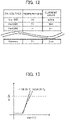
- Fig. 12 is a diagram showing an example of the on-voltage-current value calculation map 41 stored in the current calculation unit 50 of Fig. 11 .
- the map of Fig. 12 stores information about the on-voltage Von which is Vce at the time of conduction of the IGBTs 28 and 30, the temperature of each of the IGBTs 28 and 30, and the current value at the time of conduction of the IGBTs 28 and 30.
- the temperature of each of the IGBTs 28 and 30 is not limited to the temperature of the main body of each of the IGBTs 28 and 30, but as in the case of a junction temperature of each power module mounted with the IGBT, a case temperature, the average value of the temperatures of the power modules installed inside the inverter, and the temperature of a heat sink with the power module installed therein, anything that reflects the temperature information of the IGBT may be used.
- the temperature is a temperature reflecting the characteristics of the IGBT, which is the same as the temperature of the current value calculation map 39.
- Fig. 13 is a diagram showing the temperature dependence of the on-voltage Von of the IGBT and its conduction current (collector current) Ic.
- the IGBT is driven in a linear region shown in Fig. 13 , and in this linear region, the on-voltage value has a relationship of changing depending on the collector current value and the temperature.
- the on-voltage Von changes in proportion to the collector current Ic. Further, when the junction temperature Tj inside the power module increases, the on-voltage Von also increases. It is therefore necessary to provide the terms of the on-voltage value, the temperature, and the collector current value (conduction current value) in the on-voltage-current value calculation map 41.
- a method for calculating a one-phase current value (any of iu, iv, and iw) based on the current value calculation map 39 and the on-voltage-current value calculation map 41 stored in the current calculation unit 50 will be described using Fig. 14 .
- the turn-off time has the characteristic that changes depending on the power supply voltage value, the conduction current value, and the temperature. Since the power supply voltage value is acquired by the voltage sensor 52, the turn-off time is determined by defining the conduction current value and the temperature as variables. As can be seen from the on-voltage-current value calculation map 41 of Fig. 12 , the on-voltage is determined by defining the conduction current value and the temperature as variables.
- both the turn-off time and the on-voltage can be represented by two variables of the conduction current value and the temperature. Accordingly, when the turn-off time and the on-voltage take the same conduction current value and temperature, their values can be uniquely determined. With this, the conduction current value of each of the IGBTs 28 and 30 can be measured. At this time, the temperature of the IGBT can be measured at the same time.
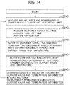
- Fig. 14 is a flowchart for measuring the load current value and the temperatures of the IGBTs 28 and 30.
- the power module (IGBT) that is turned OFF by the motor control unit 18 stores (acquires) either the upper or lower arm.
- Step S2002 the DC power supply voltage is acquired by the voltage sensor 52, the turn-off time of the IGBT is acquired (calculated) by the turn-off time measuring unit 48, and the on-voltage is acquired by the on-voltage measurement sensor 77.
- Step S2003 the conduction current value and temperature to be defined as candidates are output by referring to the IGBT turn-off time acquired in Step S2002, the DC power supply voltage value of the inverter, the on-voltage value of the IGBT, and the current (value) calculation map 39 stored in the current calculation unit 50.
- Step S2004 the conduction current value and temperature to be defined as candidates are extracted (output) by referring to the on-voltage value and the on-voltage-current (value) calculation map 41.
- step S2005 the conduction current values and temperatures (information) output in Step S2003 and Step S2004 are compared, and the most approximate conduction current value and temperature are output.
- the load current value is determined from the output conduction current value and the driving state of each of the upper and lower arms (whether the power module (IGBT) that turns OFF is either the upper or lower arm). From this flowchart, the load current value of one phase and the temperature of the switching element can be calculated. By executing the flow of Steps S2001 to S2005 in all three phases, the load current values of the three phases and the temperature of the switching IGBT can be measured.
- the information measurement unit measures the on-voltage of the power module (each of IGBTs 28 and 30 of the inverter 14).
- the current calculation unit 50 has a preset on-voltage-current value calculation map 41, and calculates the load current on the basis of the output of the turn-off time measuring unit 48, the output of the information measurement unit (on-voltage measurement sensor 77), and the on-voltage-current value calculation map 41.
- a current measurement unit that measures a load current, which combines both compact and energy saving without installing a current sensor between an inverter and a motor or inside the inverter. Also, it is possible to measure the temperature of a power module inside the inverter without installing a temperature sensor inside the inverter. Further, by using the present current measurement unit, it is possible to realize a motor drive system that combines both compact and energy-saving without installing a current sensor between the inverter and the motor or inside the inverter.
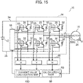
- Fig. 15 is a diagram showing the power conversion device of the present embodiment.
- the power conversion device 10 of the present embodiment is a power conversion device using a three-phase inverter as an example in a manner similar to the first embodiment.
- the points of difference from the first embodiment will be described.
- a current sensor 2000 is provided in a W phase between an inverter and a motor, and a calculation part 80 is provided in a current calculation unit 50.
- the calculation part 80 sequentially creates a current value calculation map 400 having a correspondence between a conduction current value of each of IGBTs 28 and 30 and a turn-off time thereof, based on the results of the current sensor 2000 and a W-phase turn-off time measuring unit 48.
- the current sensor 2000 may be installed in at least any one of the U phase, V phase, and W phase.
- the calculation part 80 may take the form of sequentially creating the current value calculation map 400, based on the result with the turn-off time measuring unit 48 of the same phase in which the current sensor 2000 is installed.
- Fig. 16 is a flowchart for calculating the load current value in the present embodiment.
- Step S3001 a W phase current value is acquired from the current sensor 2000, and the current value and its acquisition time are stored in the calculation part 80.
- the W phase current value is determined by S3001.
- Step S3002 the turn-off time of the IGBT and the time at which the turn-off time is acquired are stored in the calculation part 80. (Information on which arm above or below the W phase turns OFF and the turn-off time of the W phase are acquired from the motor control unit 18).
- Step S3003 the current value calculation map 400 which stores the relationship between the current value acquired at the same time and the turn-off time stored in Steps S3001 and S3002 is created.
- the current value calculation map 400 uses as an example, one in which the item of the voltage value and the term of the temperature in Fig. 3 are excluded.
- the current value acquired by the current sensor 2000 that is, the conduction current value of the IGBT is output in consideration of the information about the DC power supply voltage value of the inverter and the temperature. Therefore, the turn-off time of the IGBT and the conduction current value can be determined in a one-to-one correspondence relation.
- Step S3004 the U-phase IGBT that turns OFF stores either the upper or lower arm.
- the power module (IGBT) that turns OFF by the motor control unit 18 acquires either the upper or lower arm.
- Step S3005 the turn-off time of the IGBT is calculated (acquired).
- Step S3006 the current value is output from the turn-off time acquired in Step S3005 based on the current value calculation map 400.
- the positive/negative of the load current value can be obtained from either the upper or lower information of the switching arm.
- Steps S3004 to S3006 are similarly performed in the V phase to determine the load current values of the three phases. The order of outputting the U phase and the V phase may be reversed.
- the information measurement unit measures the current value between the power conversion device 10 and the load (motor 16).
- the information measurement unit shows an embodiment in which neither the temperature information of the power module (inverter 14) nor the DC power supply voltage 12 input to the power module (inverter 14) is included.
- the temperature sensor 20, the voltage sensor 52, and the on-voltage measurement sensor 77 are provided, and the current calculation unit 50 may be configured to calculate the load current, based on the information from each of these sensors.
- one current sensor is installed between the inverter and the motor without installing the current sensor inside the inverter, whereby it is possible to realize a current measurement unit that measures the load current, which combines compact and energy saving. Further, one current sensor is installed between the inverter and the motor without installing the current sensor inside the inverter, whereby it is possible to realize a motor drive system having both compact and energy saving.
- Fig. 17 is a diagram showing the relationship of the gate current at the turn-off of the IGBT in a reflux mode and a switching mode.
- a solid line is Ig4000 in the reflux mode, and a chain line is Ig4001 in the switching mode. Since in the reflux mode, the current is energized in the reflux diode 32 and not energized in the IGBTs 28 and 30, the turn-off time is determined only by the input capacitance of the IGBT and the gate resistance.
- tm in Fig. 17 is the above-mentioned "mirror period"
- tf indicates the turn-off time of the reflux mode
- td indicates the turn-off time of the switching mode, respectively.
- the variation in the turn-off time in the reflux mode is the variation in the RC time constant consisting of the product of the input capacitance and the gate resistance. Therefore, it is possible to correct the variation in the RC time constant between the power modules (IGBTs 28, 30), based on the turn-off time in the reflux mode.
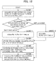
- Fig. 18 is a flowchart for calculating the load current value in the present embodiment.
- Step S4001 the IGBT turned OFF by the motor control unit 18 stores the IGBT being either the upper or lower arm.
- Step S4002 the motor control unit 18 determines that the timing for measuring the turn-off time is the "switching mode" or the "reflux mode".
- Step S4003-2 the turn-off time tf in the reflux mode is stored (acquired).
- Step S4002 when it is determined in Step S4002 that the timing is the "switching mode", the flowchart proceeds to Step S4003-1. At the time of turn-off of the switching mode, the turn-off time td is stored (acquired) in step S4003-1.
- Step S4004 the difference in td-tf during the same operation is taken, and standardization is performed on the basis of td-tf, which takes the smallest value. At this time, the magnification used for standardization is stored.
- the term “at the same operation” refers to the time when the six IGBTs 28 and 30 on the three-phase upper and lower arms perform the same operation. That is, it is "when the six IGBTs 28 and 30 operate in response to the same command signal at the same DC power supply value and the same temperature".
- Step S4005 and its subsequent Steps are a flow to calculate the current value in a manner similar to the first to third embodiments.
- Fig. 18 shows the current calculation method of the first embodiment as an example.
- Step S4006 the reference value of the turn-off time of the current value calculation map is referred to by the value multiplied by the standardized magnification stored in Step S4004.
- the IGBT_A that has the shortest turn-off time is set to "1", and stores how many times (XX times) the turn-off time of the IGBT_B at the above-mentioned "same operation" will be.
- the IGBT_B refers to the turn-off time as a value multiplied by the reciprocal of the obtained multiple (XX times).
- Step S4005 and Step S4006 of the present flow in each phase it is possible to measure the current with high accuracy even when the characteristics between the power modules of the three-phase upper and lower arms are ununiform.
- the turn-off time measuring unit 48 corrects the variation in the turn-off delay time due to the element variation, based on the turn-off delay time during the reflux period of the power module (inverter 14). As a result, it becomes possible to correct the load current value and measure the load current high in accuracy.
- the present embodiment it is possible to realize the current measurement unit measuring the load current, having both compact and energy saving without installing the current sensor between the inverter and the motor or inside the inverter, even if the feedback capacity of each power module varies. Further, by using the present current measurement unit, it is possible to realize the motor drive system that combines compact and energy-saving without installing the current sensor between the inverter and the motor or inside the inverter.
- the present invention is not limited to the above-mentioned embodiments and includes various modifications.
- the above-described embodiments have been described in detail in order to explain the present invention in an easy-to-understand manner, and are not necessarily limited to those having all the described configurations.
Landscapes
- Engineering & Computer Science (AREA)
- Power Engineering (AREA)
- Inverter Devices (AREA)
- Power Conversion In General (AREA)
Applications Claiming Priority (2)
| Application Number | Priority Date | Filing Date | Title |
|---|---|---|---|
| JP2019133945A JP7096792B2 (ja) | 2019-07-19 | 2019-07-19 | 電流計測器および電力変換装置 |
| PCT/JP2020/005351 WO2021014666A1 (fr) | 2019-07-19 | 2020-02-12 | Unité de mesure de courant et dispositif de conversion de puissance |
Publications (2)
| Publication Number | Publication Date |
|---|---|
| EP4002660A1 true EP4002660A1 (fr) | 2022-05-25 |
| EP4002660A4 EP4002660A4 (fr) | 2023-08-02 |
Family
ID=74193304
Family Applications (1)
| Application Number | Title | Priority Date | Filing Date |
|---|---|---|---|
| EP20844881.1A Pending EP4002660A4 (fr) | 2019-07-19 | 2020-02-12 | Unité de mesure de courant et dispositif de conversion de puissance |
Country Status (4)
| Country | Link |
|---|---|
| EP (1) | EP4002660A4 (fr) |
| JP (1) | JP7096792B2 (fr) |
| CN (1) | CN114008901A (fr) |
| WO (1) | WO2021014666A1 (fr) |
Families Citing this family (3)
| Publication number | Priority date | Publication date | Assignee | Title |
|---|---|---|---|---|
| JP7415880B2 (ja) * | 2020-09-02 | 2024-01-17 | 株式会社明電舎 | 半導体デバイスの温度推定装置および温度推定方法 |
| CN114325043B (zh) * | 2021-12-16 | 2023-10-17 | 华人运通(江苏)技术有限公司 | 一种提高小电流测试精度的系统及测试方法 |
| WO2023187918A1 (fr) | 2022-03-28 | 2023-10-05 | 三菱電機株式会社 | Dispositif de mesure de caractéristique de semiconducteur, procédé de mesure de caractéristique de semiconducteur, et programme |
Family Cites Families (23)
| Publication number | Priority date | Publication date | Assignee | Title |
|---|---|---|---|---|
| JP3786142B2 (ja) * | 1996-08-09 | 2006-06-14 | 株式会社安川電機 | インバータ装置 |
| JP3688448B2 (ja) * | 1997-10-02 | 2005-08-31 | 富士通株式会社 | スイッチング電源装置 |
| JP2000134954A (ja) * | 1998-10-23 | 2000-05-12 | Hitachi Ltd | インバータ装置 |
| JP3886876B2 (ja) * | 2002-01-17 | 2007-02-28 | 三菱電機株式会社 | 電力用半導体素子の駆動回路 |
| JP3933108B2 (ja) * | 2003-08-01 | 2007-06-20 | アイシン・エィ・ダブリュ株式会社 | 電動駆動制御装置、電動駆動制御方法及びそのプログラム |
| CN101165860B (zh) * | 2003-08-22 | 2010-04-07 | 关西电力株式会社 | 半导体装置及制造方法、使用该半导体装置的电力变换装置 |
| JP4338483B2 (ja) * | 2003-09-09 | 2009-10-07 | 株式会社豊田中央研究所 | インバータ出力電流測定装置 |
| JP4549159B2 (ja) * | 2004-11-05 | 2010-09-22 | 東芝三菱電機産業システム株式会社 | 巻線型誘導電動機の制御装置 |
| DE102006001874B4 (de) * | 2006-01-13 | 2012-05-24 | Infineon Technologies Ag | Verfahren und Vorrichtung zur Strom- und Temperaturmessung in einer leistungselektronischen Schaltung |
| JP2009225506A (ja) * | 2008-03-13 | 2009-10-01 | Toshiba Corp | 電力変換器 |
| JP2010142074A (ja) * | 2008-12-15 | 2010-06-24 | Toyota Motor Corp | 電力変換器制御装置 |
| WO2010103565A1 (fr) | 2009-03-10 | 2010-09-16 | 株式会社日立産機システム | Dispositif d'entraînement de moteur à courant alternatif |
| JP5448706B2 (ja) * | 2009-10-15 | 2014-03-19 | 古河電気工業株式会社 | 電流検出装置及び電流検出方法 |
| KR101089906B1 (ko) * | 2010-04-02 | 2011-12-05 | 성균관대학교산학협력단 | 최대 전력점 추종기, 전력 변환 제어기, 절연형 구조의 전력 변환 장치 및 그 최대 전력 추종 방법 |
| US8901908B2 (en) * | 2010-06-08 | 2014-12-02 | Infineon Technologies Austria Ag | Methods and apparatus for DC-DC conversion using digitally controlled adaptive pulse frequency modulation |
| JP2013055801A (ja) * | 2011-09-05 | 2013-03-21 | Nissan Motor Co Ltd | 電力変換装置 |
| CN103248227B (zh) * | 2013-05-30 | 2015-12-09 | 杭州士兰微电子股份有限公司 | 开关电源及实现恒定输出电流的开关电源控制器 |
| JP6221930B2 (ja) * | 2014-05-13 | 2017-11-01 | 株式会社デンソー | スイッチング素子の駆動回路 |
| US10191021B2 (en) * | 2015-02-27 | 2019-01-29 | Deere & Company | Method for estimating a temperature of a transistor |
| CN106610445B (zh) * | 2015-10-27 | 2019-07-12 | 全球能源互联网研究院 | 一种数字化驱动的igbt电流检测系统及其检测方法 |
| JP2017184298A (ja) | 2016-03-28 | 2017-10-05 | 株式会社日立製作所 | 電力変換装置 |
| JP6796360B2 (ja) * | 2016-11-11 | 2020-12-09 | 新電元工業株式会社 | パワーモジュール |
| CN207782681U (zh) * | 2018-01-02 | 2018-08-28 | 宁波市江北九方和荣电气有限公司 | 一种控制电路装置及具有该电路装置的能量回馈系统 |
-
2019
- 2019-07-19 JP JP2019133945A patent/JP7096792B2/ja active Active
-
2020
- 2020-02-12 WO PCT/JP2020/005351 patent/WO2021014666A1/fr not_active Ceased
- 2020-02-12 CN CN202080045422.4A patent/CN114008901A/zh active Pending
- 2020-02-12 EP EP20844881.1A patent/EP4002660A4/fr active Pending
Also Published As
| Publication number | Publication date |
|---|---|
| JP2021019435A (ja) | 2021-02-15 |
| EP4002660A4 (fr) | 2023-08-02 |
| JP7096792B2 (ja) | 2022-07-06 |
| WO2021014666A1 (fr) | 2021-01-28 |
| CN114008901A (zh) | 2022-02-01 |
Similar Documents
| Publication | Publication Date | Title |
|---|---|---|
| CN107148739B (zh) | 电力变换装置和应用该电力变换装置的车辆驱动系统 | |
| JP6274077B2 (ja) | モータ制御装置 | |
| EP0588213B1 (fr) | Méthode de mesure des constantes charactéristiques pour moteur à courant alternatif et contrÔleur à base de cette méthode | |
| CN100461613C (zh) | 兼作充电控制装置的电动机驱动装置 | |
| CN101494431B (zh) | 多相电动机控制装置 | |
| KR101297453B1 (ko) | 모터 제어 장치 및 공기 조화기 | |
| JP5470960B2 (ja) | 電力変換装置及び電力変換装置の放電方法 | |
| US10090832B2 (en) | Controller for power converter having a delaying unit | |
| US20020175644A1 (en) | Multilevel dc link inverter | |
| EP2566034A1 (fr) | Circuit de commutation | |
| EP4002660A1 (fr) | Unité de mesure de courant et dispositif de conversion de puissance | |
| KR20070116616A (ko) | 전류 제어 장치와 그 전류 오프셋 보정 방법 | |
| US20160308475A1 (en) | Control apparatus for motor control system | |
| US20250202384A1 (en) | Power conversion device and flying object | |
| CN116073692A (zh) | 确定逆变器的半导体结构元件的损耗功率的方法和装置 | |
| US12237785B2 (en) | Electrical power conversion apparatus | |
| RU2664591C1 (ru) | Способ управления электрической мощностью и устройство управления электрической мощностью | |
| JP2005124305A (ja) | 二相変調制御式インバータ装置 | |
| JP3774329B2 (ja) | インバータ装置 | |
| JP2010154726A (ja) | 電力変換器の制御方法 | |
| EP4195494A1 (fr) | Affaiblissement de flux adaptatif de charge d'un moteur synchrone à aimant permanent fonctionnant en mode de commande de tension | |
| KR20100051171A (ko) | 인버터의 전압 변조방식 전환을 통한 igbt 도통손실 저감 방법 | |
| US20210328538A1 (en) | Direct-current power supply device, motor drive device, blower, compressor, and air conditioner | |
| CN1307779C (zh) | 变换装置及其空载时间补偿方法 | |
| WO2022234832A1 (fr) | Dispositif de conversion de puissance et procédé de conversion de puissance |
Legal Events
| Date | Code | Title | Description |
|---|---|---|---|
| STAA | Information on the status of an ep patent application or granted ep patent |
Free format text: STATUS: THE INTERNATIONAL PUBLICATION HAS BEEN MADE |
|
| PUAI | Public reference made under article 153(3) epc to a published international application that has entered the european phase |
Free format text: ORIGINAL CODE: 0009012 |
|
| STAA | Information on the status of an ep patent application or granted ep patent |
Free format text: STATUS: REQUEST FOR EXAMINATION WAS MADE |
|
| 17P | Request for examination filed |
Effective date: 20211222 |
|
| AK | Designated contracting states |
Kind code of ref document: A1 Designated state(s): AL AT BE BG CH CY CZ DE DK EE ES FI FR GB GR HR HU IE IS IT LI LT LU LV MC MK MT NL NO PL PT RO RS SE SI SK SM TR |
|
| DAV | Request for validation of the european patent (deleted) | ||
| DAX | Request for extension of the european patent (deleted) | ||
| A4 | Supplementary search report drawn up and despatched |
Effective date: 20230629 |
|
| RIC1 | Information provided on ipc code assigned before grant |
Ipc: H02P 21/00 20160101ALI20230623BHEP Ipc: H02M 7/5387 20070101ALI20230623BHEP Ipc: H02M 1/32 20070101ALI20230623BHEP Ipc: H02P 21/14 20160101ALI20230623BHEP Ipc: H02M 7/48 20070101ALI20230623BHEP Ipc: H02M 1/00 20060101AFI20230623BHEP |
|
| STAA | Information on the status of an ep patent application or granted ep patent |
Free format text: STATUS: EXAMINATION IS IN PROGRESS |
|
| 17Q | First examination report despatched |
Effective date: 20240912 |