EP4002671A1 - Leistungswandlungssystem - Google Patents
Leistungswandlungssystem Download PDFInfo
- Publication number
- EP4002671A1 EP4002671A1 EP19937499.2A EP19937499A EP4002671A1 EP 4002671 A1 EP4002671 A1 EP 4002671A1 EP 19937499 A EP19937499 A EP 19937499A EP 4002671 A1 EP4002671 A1 EP 4002671A1
- Authority
- EP
- European Patent Office
- Prior art keywords
- current
- alternate
- direct
- power converter
- power
- Prior art date
- Legal status (The legal status is an assumption and is not a legal conclusion. Google has not performed a legal analysis and makes no representation as to the accuracy of the status listed.)
- Pending
Links
- 238000006243 chemical reaction Methods 0.000 title claims abstract description 37
- 239000003990 capacitor Substances 0.000 claims abstract description 56
- 238000010586 diagram Methods 0.000 description 20
- 230000006870 function Effects 0.000 description 11
- 239000004065 semiconductor Substances 0.000 description 2
- 230000007704 transition Effects 0.000 description 2
- 101150002418 cpi-2 gene Proteins 0.000 description 1
- 230000000694 effects Effects 0.000 description 1
- 230000003287 optical effect Effects 0.000 description 1
- 230000002265 prevention Effects 0.000 description 1
- 230000001629 suppression Effects 0.000 description 1
Images


Classifications
-
- H—ELECTRICITY
- H02—GENERATION; CONVERSION OR DISTRIBUTION OF ELECTRIC POWER
- H02M—APPARATUS FOR CONVERSION BETWEEN AC AND AC, BETWEEN AC AND DC, OR BETWEEN DC AND DC, AND FOR USE WITH MAINS OR SIMILAR POWER SUPPLY SYSTEMS; CONVERSION OF DC OR AC INPUT POWER INTO SURGE OUTPUT POWER; CONTROL OR REGULATION THEREOF
- H02M1/00—Details of apparatus for conversion
- H02M1/36—Means for starting or stopping converters
-
- H—ELECTRICITY
- H02—GENERATION; CONVERSION OR DISTRIBUTION OF ELECTRIC POWER
- H02M—APPARATUS FOR CONVERSION BETWEEN AC AND AC, BETWEEN AC AND DC, OR BETWEEN DC AND DC, AND FOR USE WITH MAINS OR SIMILAR POWER SUPPLY SYSTEMS; CONVERSION OF DC OR AC INPUT POWER INTO SURGE OUTPUT POWER; CONTROL OR REGULATION THEREOF
- H02M1/00—Details of apparatus for conversion
- H02M1/32—Means for protecting converters other than automatic disconnection
-
- H—ELECTRICITY
- H02—GENERATION; CONVERSION OR DISTRIBUTION OF ELECTRIC POWER
- H02M—APPARATUS FOR CONVERSION BETWEEN AC AND AC, BETWEEN AC AND DC, OR BETWEEN DC AND DC, AND FOR USE WITH MAINS OR SIMILAR POWER SUPPLY SYSTEMS; CONVERSION OF DC OR AC INPUT POWER INTO SURGE OUTPUT POWER; CONTROL OR REGULATION THEREOF
- H02M1/00—Details of apparatus for conversion
- H02M1/44—Circuits or arrangements for compensating for electromagnetic interference in converters or inverters
-
- H—ELECTRICITY
- H02—GENERATION; CONVERSION OR DISTRIBUTION OF ELECTRIC POWER
- H02M—APPARATUS FOR CONVERSION BETWEEN AC AND AC, BETWEEN AC AND DC, OR BETWEEN DC AND DC, AND FOR USE WITH MAINS OR SIMILAR POWER SUPPLY SYSTEMS; CONVERSION OF DC OR AC INPUT POWER INTO SURGE OUTPUT POWER; CONTROL OR REGULATION THEREOF
- H02M3/00—Conversion of DC power input into DC power output
- H02M3/22—Conversion of DC power input into DC power output with intermediate conversion into AC
- H02M3/24—Conversion of DC power input into DC power output with intermediate conversion into AC by static converters
- H02M3/28—Conversion of DC power input into DC power output with intermediate conversion into AC by static converters using discharge tubes with control electrode or semiconductor devices with control electrode to produce the intermediate AC
- H02M3/325—Conversion of DC power input into DC power output with intermediate conversion into AC by static converters using discharge tubes with control electrode or semiconductor devices with control electrode to produce the intermediate AC using devices of a triode or a transistor type requiring continuous application of a control signal
- H02M3/335—Conversion of DC power input into DC power output with intermediate conversion into AC by static converters using discharge tubes with control electrode or semiconductor devices with control electrode to produce the intermediate AC using devices of a triode or a transistor type requiring continuous application of a control signal using semiconductor devices only
- H02M3/33569—Conversion of DC power input into DC power output with intermediate conversion into AC by static converters using discharge tubes with control electrode or semiconductor devices with control electrode to produce the intermediate AC using devices of a triode or a transistor type requiring continuous application of a control signal using semiconductor devices only having several active switching elements
-
- H—ELECTRICITY
- H02—GENERATION; CONVERSION OR DISTRIBUTION OF ELECTRIC POWER
- H02M—APPARATUS FOR CONVERSION BETWEEN AC AND AC, BETWEEN AC AND DC, OR BETWEEN DC AND DC, AND FOR USE WITH MAINS OR SIMILAR POWER SUPPLY SYSTEMS; CONVERSION OF DC OR AC INPUT POWER INTO SURGE OUTPUT POWER; CONTROL OR REGULATION THEREOF
- H02M7/00—Conversion of AC power input into DC power output; Conversion of DC power input into AC power output
- H02M7/42—Conversion of DC power input into AC power output without possibility of reversal
- H02M7/44—Conversion of DC power input into AC power output without possibility of reversal by static converters
- H02M7/48—Conversion of DC power input into AC power output without possibility of reversal by static converters using discharge tubes with control electrode or semiconductor devices with control electrode
- H02M7/483—Converters with outputs that each can have more than two voltages levels
- H02M7/4835—Converters with outputs that each can have more than two voltages levels comprising two or more cells, each including a switchable capacitor, the capacitors having a nominal charge voltage which corresponds to a given fraction of the input voltage, and the capacitors being selectively connected in series to determine the instantaneous output voltage
-
- H—ELECTRICITY
- H02—GENERATION; CONVERSION OR DISTRIBUTION OF ELECTRIC POWER
- H02M—APPARATUS FOR CONVERSION BETWEEN AC AND AC, BETWEEN AC AND DC, OR BETWEEN DC AND DC, AND FOR USE WITH MAINS OR SIMILAR POWER SUPPLY SYSTEMS; CONVERSION OF DC OR AC INPUT POWER INTO SURGE OUTPUT POWER; CONTROL OR REGULATION THEREOF
- H02M7/00—Conversion of AC power input into DC power output; Conversion of DC power input into AC power output
- H02M7/42—Conversion of DC power input into AC power output without possibility of reversal
- H02M7/44—Conversion of DC power input into AC power output without possibility of reversal by static converters
- H02M7/48—Conversion of DC power input into AC power output without possibility of reversal by static converters using discharge tubes with control electrode or semiconductor devices with control electrode
- H02M7/53—Conversion of DC power input into AC power output without possibility of reversal by static converters using discharge tubes with control electrode or semiconductor devices with control electrode using devices of a triode or transistor type requiring continuous application of a control signal
- H02M7/537—Conversion of DC power input into AC power output without possibility of reversal by static converters using discharge tubes with control electrode or semiconductor devices with control electrode using devices of a triode or transistor type requiring continuous application of a control signal using semiconductor devices only, e.g. single switched pulse inverters
-
- H—ELECTRICITY
- H02—GENERATION; CONVERSION OR DISTRIBUTION OF ELECTRIC POWER
- H02H—EMERGENCY PROTECTIVE CIRCUIT ARRANGEMENTS
- H02H9/00—Emergency protective circuit arrangements for limiting excess current or voltage without disconnection
- H02H9/001—Emergency protective circuit arrangements for limiting excess current or voltage without disconnection limiting speed of change of electric quantities, e.g. soft switching on or off
- H02H9/002—Emergency protective circuit arrangements for limiting excess current or voltage without disconnection limiting speed of change of electric quantities, e.g. soft switching on or off limiting inrush current on switching on of inductive loads subjected to remanence, e.g. transformers
-
- H—ELECTRICITY
- H02—GENERATION; CONVERSION OR DISTRIBUTION OF ELECTRIC POWER
- H02M—APPARATUS FOR CONVERSION BETWEEN AC AND AC, BETWEEN AC AND DC, OR BETWEEN DC AND DC, AND FOR USE WITH MAINS OR SIMILAR POWER SUPPLY SYSTEMS; CONVERSION OF DC OR AC INPUT POWER INTO SURGE OUTPUT POWER; CONTROL OR REGULATION THEREOF
- H02M1/00—Details of apparatus for conversion
- H02M1/12—Arrangements for reducing harmonics from AC input or output
- H02M1/126—Arrangements for reducing harmonics from AC input or output using passive filters
-
- Y—GENERAL TAGGING OF NEW TECHNOLOGICAL DEVELOPMENTS; GENERAL TAGGING OF CROSS-SECTIONAL TECHNOLOGIES SPANNING OVER SEVERAL SECTIONS OF THE IPC; TECHNICAL SUBJECTS COVERED BY FORMER USPC CROSS-REFERENCE ART COLLECTIONS [XRACs] AND DIGESTS
- Y02—TECHNOLOGIES OR APPLICATIONS FOR MITIGATION OR ADAPTATION AGAINST CLIMATE CHANGE
- Y02B—CLIMATE CHANGE MITIGATION TECHNOLOGIES RELATED TO BUILDINGS, e.g. HOUSING, HOUSE APPLIANCES OR RELATED END-USER APPLICATIONS
- Y02B70/00—Technologies for an efficient end-user side electric power management and consumption
- Y02B70/10—Technologies improving the efficiency by using switched-mode power supplies [SMPS], i.e. efficient power electronics conversion e.g. power factor correction or reduction of losses in power supplies or efficient standby modes
Definitions
- the present invention relates to a power conversion system that alternate-current power to direct-current power or direct-current power to alternate-current power or compensates reactive power of an alternate-current power supply.
- Patent Literature 1 discloses a power conversion system.
- the power conversion system enables performing initial charging of a direct-current capacitor while suppressing inrush current.
- An object of the present invention is to provide a power conversion system that enables performing initial charging of a direct-current capacitor while suppressing inrush current without using a component having a high rating.
- a power conversion system includes: a power converter connected to an alternate-current power supply; a direct-current capacitor connected to a direct-current side of the power converter; a first alternate-current switch connected between the power converter and the alternate-current power supply; an inrush current suppressor connected in parallel to the first alternate-current switch, between the power converter and the alternate-current power supply, the inrush current suppressor including a charging resistance or a charging reactor; a second alternate-current switch connected in parallel to the first alternate-current switch and in series to the inrush current suppressor, between the power converter and the alternate-current power supply; and a control device configured to control the power converter so that the first alternate-current switch is open, the second alternate-current switch is closed and a voltage applied to the direct-current capacitor reaches a voltage that is equal to or exceeds a preset voltage.
- the present invention thus enables performing initial charging of a direct-current capacitor while suppressing inrush current without using a component having a high rating.
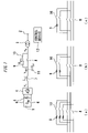
- Fig. 1 is a configuration diagram of a system to which a power conversion system according to Embodiment 1 is applied.
- a direct-current power supply 1 is a photovoltaic facility.
- An alternate-current power supply 2 has three phases and is operated by, e.g., an electric power company.
- a transformer 3 is connected between the direct-current power supply 1 and the alternate-current power supply 2.
- the power conversion system includes a power converter 4, a direct-current capacitor 5, direct-current switches 6, an alternate-current reactor 7, a first alternate-current switch 8 a charging resistance 9, a second alternate-current switch 10, an alternate-current capacitor 11 and a control device 12.
- the power converter 4 is connected between the direct-current power supply 1 and the transformer 3.
- the direct-current capacitor 5 is connected between the direct-current power supply 1 and the power converter 4.
- the direct-current switches 6 are connected between the direct-current power supply 1 and the power converter 4.
- the alternate-current reactor 7 is connected between the power converter 4 and the transformer 3.
- the first alternate-current switch 8 is connected between the alternate-current reactor 7 and the transformer 3.
- the charging resistance 9 is connected in parallel to the first alternate-current switch 8, between the alternate-current reactor 7 and the transformer 3.
- the second alternate-current switch 10 is connected in parallel to the first alternate-current switch 8 and in series to the charging resistance 9, between the alternate-current reactor 7 and the transformer 3.
- the alternate-current capacitor 11 is connected to the alternate-current reactor 7 side relative to the first alternate-current switch 8, the charging resistance 9 and the second alternate-current switch 10, on the output side of the power converter 4.
- the first alternate-current switch 8, the charging resistance 9 and the second alternate-current switch 10 may have any of the forms in (a), (b) and (c) in the lower part of Fig. 1 .
- the control device 12 is provided so as to be capable of controlling the power converter 4, the direct-current switches 6, the first alternate-current switch 8 and the second alternate-current switch 10.
- control device 12 Next, a series of controls by the control device 12 will be described with reference to Figs. 2 to 6 .
- Fig. 2 is a diagram for describing a charging start mode provided by a control device in the power conversion system according to Embodiment 1.
- Fig. 3 is a diagram for describing a boost charging mode provided by the control device in the power conversion system according to Embodiment 1.
- Fig. 4 is a diagram for describing an alternate-current voltage synchronization mode provided by the control device in the power conversion system according to Embodiment 1.
- Fig. 5 is a diagram for describing a standby mode provided by the control device in the power conversion system according to Embodiment 1.
- Fig. 6 is a diagram for describing an SVC operation mode provided by the control device in the power conversion system according to Embodiment 1.
- the SVC (staric var compensator) operation mode refers to an operation mode in which reactive power compensation is performed.
- the control device 12 provides a state in which the direct-current switches 6 are open, the first alternate-current switch 8 is open and the power converter 4 is stopped, and closes the second alternate-current switch 10. At this time, an electrostatic capacitance Cdc of the direct-current capacitor 5 is charged via the charging resistance 9. Where impedances of the transformer 3 and the alternate-current power supply 2 can be ignored, a direct-current voltage Vi reaches approximately a value expressed by Expression (1) below.
- V 1 2 V s 1 + 3 ⁇ R prc C pi 2
- ⁇ is an angular speed corresponding to a frequency of the alternate-current power supply 2.
- R prc is a resistance value of the charging resistance 9.
- C pi is an electrostatic capacitance of the alternate-current capacitor 11.
- V s is a rated voltage of the alternate-current power supply 2.
- the control device 12 controls the power converter 4 to perform boosting, and performs charging until the direct-current voltage V 1 reaches a preset value that is equal to or exceeds a value according to Expression (2) below.
- the control device 12 controls the power converter 4 to supply reactive power to the alternate-current side, and then, when a voltage v cpi applied to the alternate-current capacitor 11 has been brought into agreement with a present voltage vs of the alternate-current power supply 2, the control device 12 closes the first alternate-current switch 8.
- control device 12 performs control so that an output current of the power converter 4 becomes zero.
- control device 12 controls the power converter 4 to compensate reactive power on the alternate-current side.
- Fig. 7 is a diagram for describing charged power of a direct-current capacitor in the power conversion system according to Embodiment 1.
- i R is a vector of current flowing in the charging resistance 9.
- an instantaneous active power p 1 is equal to the instantaneous active power p 2 . Therefore, the charged power of the direct-current capacitor 5 can be controlled by manipulating the voltage vector v cpi applied to the alternate-current capacitor 11.
- the instantaneous active power p 2 is symmetrical with respect to v sd .
- the instantaneous active power p 1 is smaller than power consumption p R of the charging resistance 9.
- the instantaneous active power p 1 is larger than the power consumption p R of the charging resistance 9.
- v cpid be within a range of v sd /2 ⁇ v cpid ⁇ V sd .
- Fig. 8 is a diagram for describing control during the boost charging mode in the power conversion system according to Embodiment 1.
- an impedance L si of the alternate-current reactor 7 for a frequency f of the alternate-current power supply 2 is sufficiently small in comparison with a complex impedance of the electrostatic capacitance C pi of the alternate-current capacitor 11 and the resistance value R prc of the charging resistance 9. Therefore, if current i i flowing in the charging resistance 9 is not so large, the voltage v cpi applied to the alternate-current capacitor 11 agrees with an output voltage vi of the power converter 4. At this time, the control device 12 sets a voltage instruction value v i ⁇ for the power converter 4 to a value expressed by Expression (10) below.
- k is adjusted within a range of no less than 0 but no more than 1. Where k is 1, the direct-current capacitor 5 is charged with substantially theoretical maximum power. Where k is 0, the direct-current capacitor 5 is not charged.
- charging of the direct-current capacitor 5 is performed with k set to 1. If charged power is excessively large or if power consumption of the charging resistance 9 is excessively large, charging of the direct-current capacitor 5 is performed with k appropriately adjusted.
- Fig. 9 is a diagram for describing control during the alternate-current voltage synchronization mode in the power conversion system according to Embodiment 1.
- the power converter 4 supplies only reactive power in order to bring the voltage v cpi applied to the alternate-current capacitor 11 into agreement with the present voltage vs of the alternate-current power supply 2. In theory, no active power is required and thus the direct-current voltage is not lowered.
- control device 12 Next, an overview of operation of the control device 12 will be described with reference to Fig. 10 .
- Fig. 10 is a flowchart for describing an overview of operation of the control device in the power conversion system according to Embodiment 1.
- step S1 the control device 12 closes the second alternate-current switch 10. Subsequently, the control device 12 performs operation in step S2.
- step S2 the control device 12 controls the power converter 4 so that a voltage applied to the direct-current capacitor 5 reaches a value that is equal to or exceeds a present value. Subsequently, the control device 12 performs operation in step S3.
- step S3 the control device 12 controls the power converter 4 so that a voltage applied to the alternate-current capacitor 11 agrees with a voltage of the alternate-current power supply 2. Subsequently, the control device 12 performs operation in step S4.
- step S4 the control device 12 controls the power converter 4 so that an output current becomes zero simultaneously with closing of the first alternate-current switch 8. Subsequently, the control device 12 performs operation in step S5.
- step S5 the control device 12 controls the power converter 4 so as to compensate reactive power on the alternate-current side.
- the control device 12 provides a state in which the direct-current switches 6 are open, the first alternate-current switch 8 is open, the second alternate-current switch 10 is closed and the power converter 4 is stopped, and controls the power converter 4 so that the voltage applied to the direct-current capacitor 5 reaches a value that is equal to or exceeds the preset voltage. Therefore, it is possible to perform initial charging of the direct-current capacitor 5 while suppressing inrush current without using a component having a high rating.
- control device 12 controls the power converter 4 so that the voltage applied to the alternate-current capacitor 11 agrees with the voltage of the alternate-current power supply 2. Subsequently, the control device 12 closes the first alternate-current switch 8. Therefore, it is possible to suppress inrush current flowing in the alternate-current capacitor 11.
- the control device 12 controls the power converter 4 so as to compensate reactive power on the alternate-current side. Therefore, reactive power on the alternate-current side can be compensated with suppression of inrush current at the time of initial charging of the direct-current capacitor 5.
- a storage battery may be used as the direct-current power supply 1.
- the direct-current switches 6 may be closed after controlling the power converter 4 so that the voltage applied to the direct-current capacitor 5 agrees with a charged voltage of the storage battery, following the standby mode or the alternate-current voltage synchronization mode. In this case, also, inrush current flowing in the direct-current capacitor 5 when closing the direct-current switches 6 can be suppressed.
- a charging reactor may be used instead of the charging resistance 9. In this case, also, it is possible to perform initial charging of the direct-current capacitor 5 while suppressing inrush current without using a component having a high rating.
- the charging start mode is not necessary. Therefore, the mode may transition to the boost charging mode simultaneously with closure of the second alternate-current switch 10. In this case, power consumption of the charging resistance 9 may be suppressed.
- the switch 8 may be turned on before the voltages of the alternate-current capacitor 11 and the alternate-current power supply 2 are brought into agreement with each other.
- the mode may transition from the alternate-current voltage synchronization mode to the SVC operation mode without involving the standby mode.
- the direct-current switches 6 may be left consistently on. Also, the direct-current power supply and the direct-current side of the power converter may directly be connected with no direct-current switches 6 provided.
- the direct-current power supply and the direct-current side of the power converter may be connected via a backflow prevention semiconductor device such as a diode, with no direct-current switches 6 provided.
- the present invention is applicable even if no alternate-current capacitor 11 is provided.
- the alternate-current power supply 2 may be a single-phase power supply and the power converter 4 may be a single-phase power converter.
- the boost charging mode where a present voltage vs of the single-phase power supply satisfies Expression (12) below, the instantaneous active power p 2 reaches a maximum value expressed by Expression (13) below.
- control device 12 Next, an example of the control device 12 will be described with reference to Fig. 11 .
- Fig. 11 is a hardware configuration diagram of the control device in the power conversion system according to Embodiment 1.
- Each of functions of the control device 12 can be implemented by processing circuitry.
- the processing circuitry includes at least one processor 100a and at least one memory 100b.
- the processing circuitry includes at least one dedicated hardware piece 200.
- each of the functions of the control device 12 is implemented by software, firmware or a combination of software and firmware. At least one of the software and the firmware is described in the form of programs. At least one of the software and the firmware is stored in the at least one memory 100b.
- the at least one processor 100a implements respective functions of the control device 12 by reading and executing the programs stored in the at least one memory 100b.
- the at least one processor 100a is also referred to as a central processing unit, a processing device, an arithmetic device, a microprocessor, a microcomputer or a DSP.
- the at least one memory 100b is a non-volatile or volatile semiconductor memory such as a RAM, a ROM, a flash memory, an EPROM or a EEPROM, a magnetic disk, a flexible disk, an optical disk, a compact disc, a mini-disk or a DVD
- the processing circuitry includes the at least one dedicated hardware piece 200
- the processing circuitry is implemented by, for example, a single circuit, a complex circuit, a programmed processor, a parallel-programmed processor, an ASIC, an FPGA or any of combinations thereof.
- the functions of the control device 12 are implemented by respective processing circuits.
- the functions of the control device 12 are collectively implemented by the processing circuitry.
- control device 12 may be implemented by the dedicated hardware piece 200 and others of the functions may be implemented by the software or the firmware.
- a function that controls the power converter 4 may be implemented by the processing circuitry serving as the dedicated hardware piece 200 and the functions other than the function that controls the power converter 4 may be implemented by the at least one processor 100a reading and executing programs stored in the at least one memory 100b.
- the processing circuitry implements each of the functions of the control device 12 by means of the hardware piece 200, the software, the firmware or any of combinations thereof.
- a power conversion system according to the present invention can be used for a system that suppresses inrush current.
Landscapes
- Engineering & Computer Science (AREA)
- Power Engineering (AREA)
- Physics & Mathematics (AREA)
- Electromagnetism (AREA)
- Inverter Devices (AREA)
- Dc-Dc Converters (AREA)
- Rectifiers (AREA)
Applications Claiming Priority (1)
| Application Number | Priority Date | Filing Date | Title |
|---|---|---|---|
| PCT/JP2019/027928 WO2021009848A1 (ja) | 2019-07-16 | 2019-07-16 | 電力変換システム |
Publications (2)
| Publication Number | Publication Date |
|---|---|
| EP4002671A1 true EP4002671A1 (de) | 2022-05-25 |
| EP4002671A4 EP4002671A4 (de) | 2023-01-18 |
Family
ID=74210266
Family Applications (1)
| Application Number | Title | Priority Date | Filing Date |
|---|---|---|---|
| EP19937499.2A Pending EP4002671A4 (de) | 2019-07-16 | 2019-07-16 | Leistungswandlungssystem |
Country Status (5)
| Country | Link |
|---|---|
| US (1) | US11863063B2 (de) |
| EP (1) | EP4002671A4 (de) |
| JP (1) | JP6958749B2 (de) |
| CN (1) | CN112840550B (de) |
| WO (1) | WO2021009848A1 (de) |
Families Citing this family (3)
| Publication number | Priority date | Publication date | Assignee | Title |
|---|---|---|---|---|
| CN112510762B (zh) * | 2021-02-03 | 2021-05-04 | 浙江艾罗网络能源技术股份有限公司 | 一种并网逆变器的继电器吸合控制方法及控制装置 |
| EP4287477A1 (de) * | 2022-06-01 | 2023-12-06 | AEG Power Solutions GmbH | Dreiphasen-gleichrichter mit transformator, gesteuerter sechspuls-brückenschaltung, zwischenkreiskondensator und vorladeschaltung |
| JP7552930B2 (ja) * | 2022-09-01 | 2024-09-18 | 株式会社Tmeic | 電力変換システム |
Family Cites Families (17)
| Publication number | Priority date | Publication date | Assignee | Title |
|---|---|---|---|---|
| JPH09205740A (ja) * | 1996-01-24 | 1997-08-05 | Toshiba Corp | 無停電電源装置の起動方法 |
| JP2004147465A (ja) * | 2002-10-25 | 2004-05-20 | Canon Inc | 変換装置 |
| JP2005333770A (ja) * | 2004-05-21 | 2005-12-02 | Sanyo Electric Co Ltd | 自動車用インバータ装置 |
| DE102009025363B9 (de) * | 2009-06-18 | 2012-06-21 | Adensis Gmbh | Anfahrquelle Wechselrichter |
| CN102545678B (zh) * | 2012-02-16 | 2014-07-09 | 朱建国 | 逆变器及其启机方法 |
| JP5538658B2 (ja) * | 2012-05-24 | 2014-07-02 | 三菱電機株式会社 | 電力変換装置 |
| DE102013102603B4 (de) | 2013-03-14 | 2017-02-09 | Sma Solar Technology Ag | Verfahren für einen Schwarzstart eines Kraftwerks mit mehreren einem Wechselstromnetz zuschaltbaren Wechselrichtern |
| DE102013008586A1 (de) * | 2013-05-17 | 2014-11-20 | Audi Ag | Vorladen eines Kraftfahrzeug-Hochvoltnetzes |
| US9925933B2 (en) * | 2013-08-30 | 2018-03-27 | Ford Global Technologies, Llc | Pre-charge quick key cycling protection |
| US9722458B2 (en) | 2013-10-15 | 2017-08-01 | Toshiba Mitsubishi-Electric Industrial Systems Corporation | Power conversion device and method of controlling the same |
| FI125183B (en) | 2014-06-11 | 2015-06-30 | Abb Technology Oy | Method for charging capacitance coupled between DC terminals of three-phase active rectifier / inverter and converter device |
| JP6243801B2 (ja) * | 2014-06-12 | 2017-12-06 | 株式会社日立製作所 | 電力変換装置 |
| CN104300777B (zh) | 2014-11-07 | 2017-06-23 | 深圳市永联科技股份有限公司 | 一种逆变器同步并网方法 |
| EP3035514B1 (de) * | 2014-12-19 | 2018-06-06 | Siemens Aktiengesellschaft | Vorladevorrichtung eines Stromrichters |
| WO2017125769A1 (en) * | 2016-01-18 | 2017-07-27 | University Of Split, Faculty Of Electrical Engineering, Mechanical Engineering And Naval Arichitecture | System for dc link precharging in active front end frequency converters |
| US20190044377A1 (en) * | 2016-04-21 | 2019-02-07 | Toshiba Mitsubishi-Electric-Industrial Systems Corporation | Uninterruptible power supply |
| WO2019077958A1 (ja) * | 2017-10-17 | 2019-04-25 | 株式会社村田製作所 | 電源装置、電力制御装置、電源装置のリレー判定方法 |
-
2019
- 2019-07-16 CN CN201980067416.6A patent/CN112840550B/zh active Active
- 2019-07-16 US US17/284,637 patent/US11863063B2/en active Active
- 2019-07-16 JP JP2020559574A patent/JP6958749B2/ja active Active
- 2019-07-16 EP EP19937499.2A patent/EP4002671A4/de active Pending
- 2019-07-16 WO PCT/JP2019/027928 patent/WO2021009848A1/ja not_active Ceased
Also Published As
| Publication number | Publication date |
|---|---|
| JP6958749B2 (ja) | 2021-11-02 |
| EP4002671A4 (de) | 2023-01-18 |
| CN112840550A (zh) | 2021-05-25 |
| CN112840550B (zh) | 2024-08-30 |
| US11863063B2 (en) | 2024-01-02 |
| WO2021009848A1 (ja) | 2021-01-21 |
| US20210399627A1 (en) | 2021-12-23 |
| JPWO2021009848A1 (ja) | 2021-09-13 |
Similar Documents
| Publication | Publication Date | Title |
|---|---|---|
| EP1852963B1 (de) | Stromrichteranordnung | |
| EP1833153B1 (de) | Elektrisches Motorenstartsystem mit aktivem Gleichrichter | |
| US5262935A (en) | Parallel inverter control apparatus | |
| EP4002671A1 (de) | Leistungswandlungssystem | |
| CN102208878B (zh) | 直流到三相交流逆变器系统 | |
| EP3420618B1 (de) | Verfahren zur reduzierung von einschaltströmen in einem unterbrechungsfreien stromversorgungssystem eines transformatorlosen gleichrichters | |
| US9680368B2 (en) | Power converter installed between an electric power system and an energy storage device | |
| EP3713068A2 (de) | Matrixumwandler zum betrieb im stromregelmodus unter verwendung von vorsteuerungssignalen | |
| US20190265663A1 (en) | Method And Control System For Controlling A Voltage Source Converter Using Power-Synchronization Control | |
| US20220271684A1 (en) | Power converter | |
| JP2011050228A (ja) | 無停電電源システム | |
| US11632032B2 (en) | Power converter with output misconnection determiner | |
| US10581338B2 (en) | Power supply system | |
| US11973351B2 (en) | Power converter | |
| Segaran et al. | High-performance bi-directional AC-DC converters for PHEV with minimised DC bus capacitance | |
| US11489341B2 (en) | Power conversion system | |
| US12355245B2 (en) | Reactive power compensation device | |
| JP6296878B2 (ja) | 系統連系インバータおよび発電電力推定方法 | |
| CN115224724A (zh) | 一种含滤波电容的储能系统的三相并网连接方法 | |
| EP4012916A1 (de) | Stromumwandlungsvorrichtung | |
| US12556031B2 (en) | Uninterruptible power supply device | |
| JP2012235588A (ja) | 系統連系装置 | |
| EP4738680A1 (de) | Spannungssteuerungsvorrichtung und spannungssteuerungsverfahren | |
| JP2016052167A (ja) | 電力変換装置 | |
| JP2023084957A (ja) | 電力変換装置 |
Legal Events
| Date | Code | Title | Description |
|---|---|---|---|
| STAA | Information on the status of an ep patent application or granted ep patent |
Free format text: STATUS: THE INTERNATIONAL PUBLICATION HAS BEEN MADE |
|
| PUAI | Public reference made under article 153(3) epc to a published international application that has entered the european phase |
Free format text: ORIGINAL CODE: 0009012 |
|
| STAA | Information on the status of an ep patent application or granted ep patent |
Free format text: STATUS: REQUEST FOR EXAMINATION WAS MADE |
|
| 17P | Request for examination filed |
Effective date: 20210421 |
|
| AK | Designated contracting states |
Kind code of ref document: A1 Designated state(s): AL AT BE BG CH CY CZ DE DK EE ES FI FR GB GR HR HU IE IS IT LI LT LU LV MC MK MT NL NO PL PT RO RS SE SI SK SM TR |
|
| DAV | Request for validation of the european patent (deleted) | ||
| DAX | Request for extension of the european patent (deleted) | ||
| REG | Reference to a national code |
Ref country code: DE Ref legal event code: R079 Free format text: PREVIOUS MAIN CLASS: H02M0007480000 Ipc: H02M0007537000 |
|
| A4 | Supplementary search report drawn up and despatched |
Effective date: 20221221 |
|
| RIC1 | Information provided on ipc code assigned before grant |
Ipc: H02M 1/44 20070101ALI20221215BHEP Ipc: H02H 9/00 20060101ALI20221215BHEP Ipc: H02J 3/42 20060101ALI20221215BHEP Ipc: H02M 1/12 20060101ALI20221215BHEP Ipc: H02M 1/36 20070101ALI20221215BHEP Ipc: H02M 7/537 20060101AFI20221215BHEP |
|
| STAA | Information on the status of an ep patent application or granted ep patent |
Free format text: STATUS: EXAMINATION IS IN PROGRESS |
|
| 17Q | First examination report despatched |
Effective date: 20240314 |