EP4002675B1 - Verfahren und vorrichtung zur schätzung der rotorposition einer elektrischen synchronmaschine - Google Patents
Verfahren und vorrichtung zur schätzung der rotorposition einer elektrischen synchronmaschine Download PDFInfo
- Publication number
- EP4002675B1 EP4002675B1 EP21208696.1A EP21208696A EP4002675B1 EP 4002675 B1 EP4002675 B1 EP 4002675B1 EP 21208696 A EP21208696 A EP 21208696A EP 4002675 B1 EP4002675 B1 EP 4002675B1
- Authority
- EP
- European Patent Office
- Prior art keywords
- rotor
- electrical machine
- signals
- synchronous electrical
- estimation method
- Prior art date
- Legal status (The legal status is an assumption and is not a legal conclusion. Google has not performed a legal analysis and makes no representation as to the accuracy of the status listed.)
- Active
Links
Images

Classifications
-
- H—ELECTRICITY
- H02—GENERATION; CONVERSION OR DISTRIBUTION OF ELECTRIC POWER
- H02P—CONTROL OR REGULATION OF ELECTRIC MOTORS, ELECTRIC GENERATORS OR DYNAMO-ELECTRIC CONVERTERS; CONTROLLING TRANSFORMERS, REACTORS OR CHOKE COILS
- H02P5/00—Arrangements specially adapted for regulating or controlling the speed or torque of two or more electric motors
- H02P5/46—Arrangements specially adapted for regulating or controlling the speed or torque of two or more electric motors for speed regulation of two or more dynamo-electric motors in relation to one another
-
- H—ELECTRICITY
- H02—GENERATION; CONVERSION OR DISTRIBUTION OF ELECTRIC POWER
- H02P—CONTROL OR REGULATION OF ELECTRIC MOTORS, ELECTRIC GENERATORS OR DYNAMO-ELECTRIC CONVERTERS; CONTROLLING TRANSFORMERS, REACTORS OR CHOKE COILS
- H02P21/00—Arrangements or methods for the control of electric machines by vector control, e.g. by control of field orientation
- H02P21/14—Estimation or adaptation of machine parameters, e.g. flux, current or voltage
- H02P21/18—Estimation of position or speed
-
- H—ELECTRICITY
- H02—GENERATION; CONVERSION OR DISTRIBUTION OF ELECTRIC POWER
- H02P—CONTROL OR REGULATION OF ELECTRIC MOTORS, ELECTRIC GENERATORS OR DYNAMO-ELECTRIC CONVERTERS; CONTROLLING TRANSFORMERS, REACTORS OR CHOKE COILS
- H02P1/00—Arrangements for starting electric motors or dynamo-electric converters
- H02P1/02—Details of starting control
- H02P1/04—Means for controlling progress of starting sequence in dependence upon time or upon current, speed, or other motor parameter
-
- H—ELECTRICITY
- H02—GENERATION; CONVERSION OR DISTRIBUTION OF ELECTRIC POWER
- H02P—CONTROL OR REGULATION OF ELECTRIC MOTORS, ELECTRIC GENERATORS OR DYNAMO-ELECTRIC CONVERTERS; CONTROLLING TRANSFORMERS, REACTORS OR CHOKE COILS
- H02P21/00—Arrangements or methods for the control of electric machines by vector control, e.g. by control of field orientation
- H02P21/04—Arrangements or methods for the control of electric machines by vector control, e.g. by control of field orientation specially adapted for very low speeds
-
- H—ELECTRICITY
- H02—GENERATION; CONVERSION OR DISTRIBUTION OF ELECTRIC POWER
- H02P—CONTROL OR REGULATION OF ELECTRIC MOTORS, ELECTRIC GENERATORS OR DYNAMO-ELECTRIC CONVERTERS; CONTROLLING TRANSFORMERS, REACTORS OR CHOKE COILS
- H02P21/00—Arrangements or methods for the control of electric machines by vector control, e.g. by control of field orientation
- H02P21/13—Observer control, e.g. using Luenberger observers or Kalman filters
-
- H—ELECTRICITY
- H02—GENERATION; CONVERSION OR DISTRIBUTION OF ELECTRIC POWER
- H02P—CONTROL OR REGULATION OF ELECTRIC MOTORS, ELECTRIC GENERATORS OR DYNAMO-ELECTRIC CONVERTERS; CONTROLLING TRANSFORMERS, REACTORS OR CHOKE COILS
- H02P21/00—Arrangements or methods for the control of electric machines by vector control, e.g. by control of field orientation
- H02P21/22—Current control, e.g. using a current control loop
-
- H—ELECTRICITY
- H02—GENERATION; CONVERSION OR DISTRIBUTION OF ELECTRIC POWER
- H02P—CONTROL OR REGULATION OF ELECTRIC MOTORS, ELECTRIC GENERATORS OR DYNAMO-ELECTRIC CONVERTERS; CONTROLLING TRANSFORMERS, REACTORS OR CHOKE COILS
- H02P23/00—Arrangements or methods for the control of AC motors characterised by a control method other than vector control
- H02P23/03—Arrangements or methods for the control of AC motors characterised by a control method other than vector control specially adapted for very low speeds
-
- H—ELECTRICITY
- H02—GENERATION; CONVERSION OR DISTRIBUTION OF ELECTRIC POWER
- H02P—CONTROL OR REGULATION OF ELECTRIC MOTORS, ELECTRIC GENERATORS OR DYNAMO-ELECTRIC CONVERTERS; CONTROLLING TRANSFORMERS, REACTORS OR CHOKE COILS
- H02P23/00—Arrangements or methods for the control of AC motors characterised by a control method other than vector control
- H02P23/12—Observer control, e.g. using Luenberger observers or Kalman filters
-
- H—ELECTRICITY
- H02—GENERATION; CONVERSION OR DISTRIBUTION OF ELECTRIC POWER
- H02P—CONTROL OR REGULATION OF ELECTRIC MOTORS, ELECTRIC GENERATORS OR DYNAMO-ELECTRIC CONVERTERS; CONTROLLING TRANSFORMERS, REACTORS OR CHOKE COILS
- H02P23/00—Arrangements or methods for the control of AC motors characterised by a control method other than vector control
- H02P23/14—Estimation or adaptation of motor parameters, e.g. rotor time constant, flux, speed, current or voltage
-
- H—ELECTRICITY
- H02—GENERATION; CONVERSION OR DISTRIBUTION OF ELECTRIC POWER
- H02P—CONTROL OR REGULATION OF ELECTRIC MOTORS, ELECTRIC GENERATORS OR DYNAMO-ELECTRIC CONVERTERS; CONTROLLING TRANSFORMERS, REACTORS OR CHOKE COILS
- H02P25/00—Arrangements or methods for the control of AC motors characterised by the kind of AC motor or by structural details
- H02P25/02—Arrangements or methods for the control of AC motors characterised by the kind of AC motor or by structural details characterised by the kind of motor
- H02P25/022—Synchronous motors
- H02P25/03—Synchronous motors with brushless excitation
-
- H—ELECTRICITY
- H02—GENERATION; CONVERSION OR DISTRIBUTION OF ELECTRIC POWER
- H02P—CONTROL OR REGULATION OF ELECTRIC MOTORS, ELECTRIC GENERATORS OR DYNAMO-ELECTRIC CONVERTERS; CONTROLLING TRANSFORMERS, REACTORS OR CHOKE COILS
- H02P6/00—Arrangements for controlling synchronous motors or other dynamo-electric motors using electronic commutation dependent on the rotor position; Electronic commutators therefor
- H02P6/14—Electronic commutators
- H02P6/16—Circuit arrangements for detecting position
-
- H—ELECTRICITY
- H02—GENERATION; CONVERSION OR DISTRIBUTION OF ELECTRIC POWER
- H02P—CONTROL OR REGULATION OF ELECTRIC MOTORS, ELECTRIC GENERATORS OR DYNAMO-ELECTRIC CONVERTERS; CONTROLLING TRANSFORMERS, REACTORS OR CHOKE COILS
- H02P6/00—Arrangements for controlling synchronous motors or other dynamo-electric motors using electronic commutation dependent on the rotor position; Electronic commutators therefor
- H02P6/14—Electronic commutators
- H02P6/16—Circuit arrangements for detecting position
- H02P6/17—Circuit arrangements for detecting position and for generating speed information
-
- H—ELECTRICITY
- H02—GENERATION; CONVERSION OR DISTRIBUTION OF ELECTRIC POWER
- H02P—CONTROL OR REGULATION OF ELECTRIC MOTORS, ELECTRIC GENERATORS OR DYNAMO-ELECTRIC CONVERTERS; CONTROLLING TRANSFORMERS, REACTORS OR CHOKE COILS
- H02P6/00—Arrangements for controlling synchronous motors or other dynamo-electric motors using electronic commutation dependent on the rotor position; Electronic commutators therefor
- H02P6/14—Electronic commutators
- H02P6/16—Circuit arrangements for detecting position
- H02P6/18—Circuit arrangements for detecting position without separate position detecting elements
-
- H—ELECTRICITY
- H03—ELECTRONIC CIRCUITRY
- H03H—IMPEDANCE NETWORKS, e.g. RESONANT CIRCUITS; RESONATORS
- H03H17/00—Networks using digital techniques
- H03H17/02—Frequency selective networks
- H03H17/0202—Two or more dimensional filters; Filters for complex signals
-
- H—ELECTRICITY
- H02—GENERATION; CONVERSION OR DISTRIBUTION OF ELECTRIC POWER
- H02P—CONTROL OR REGULATION OF ELECTRIC MOTORS, ELECTRIC GENERATORS OR DYNAMO-ELECTRIC CONVERTERS; CONTROLLING TRANSFORMERS, REACTORS OR CHOKE COILS
- H02P2207/00—Indexing scheme relating to controlling arrangements characterised by the type of motor
- H02P2207/05—Synchronous machines, e.g. with permanent magnets or DC excitation
-
- H—ELECTRICITY
- H03—ELECTRONIC CIRCUITRY
- H03H—IMPEDANCE NETWORKS, e.g. RESONANT CIRCUITS; RESONATORS
- H03H17/00—Networks using digital techniques
- H03H17/02—Frequency selective networks
- H03H17/0202—Two or more dimensional filters; Filters for complex signals
- H03H2017/0205—Kalman filters
Definitions
- the invention relates to the control of rotating electrical machines. More particularly, the invention relates to a method allowing the estimation of the position of a rotor of a rotating electrical machine. The invention is particularly suitable for estimating the position of a rotor of a rotating electrical machine operating at low speed or when stopped.
- the invention finds particular utility in the field of rotating machines operating without a mechanical rotor position sensor, such as in the field of aeronautics where the current trend is to limit the on-board mass within aircraft.
- Rotating electric machines such as brushless and multi-stage synchronous machines are used on a large scale in the field of aeronautics. For example, these can be used to provide strong torque during the start-up phases of the reactors with which they are associated.
- the mechanical integration of the rotor position sensor at the machine level can be a real problem. Indeed, the compactness of current synchronous machines desired by aircraft manufacturers is an obstacle to the insertion of such sensors.
- the injection of high frequency signals at the level of the rotor can be considered because it allows an estimation of the position from a current induced at the level of the stator which contains the information on the position without uncertainty about polarity.
- all of the harmonics induced at the stator level have a lower amplitude for the same quantity of signals injected in comparison with any injection method at the stator level, which implies less significant disturbances.
- certain elements, such as rectifier bridges make it difficult to inject a signal directly at the rotor.
- the invention aims to overcome all or part of the problems cited above by proposing a method for estimating the position of a rotor from the stator current of a rotating electrical machine via harmonics naturally existing in the current. stator of the rotating electric machine. This estimate is therefore obtained without significantly modifying the existing system and without injecting additional signals either to the rotor or to the stator which could introduce torque disturbances.
- An analysis of the stator currents allows the position to be estimated directly without polarity uncertainty and without adding additional measurements.
- the position estimation is made robust in the context of a more electric aircraft.
- the invention makes it possible to improve the reliability of the overall system, which represents a major interest, for example, in the field of aeronautics where avionics systems must be as reliable as possible.
- the invention is defined in independent method claim 1 and independent device claim 12.
- the preferred embodiments are defined in dependent claims 2 to 11 and 13.
- an electric machine comprises an inverted electric machine and at least one synchronous electric machine equipped with the estimation device.
- main machine designates, here, any synchronous rotating electrical machine, whether or not equipped with one or more shock absorbers.
- exciter designates any rotating electrical machine synchronous in reverse with respect to the main machine.
- the exciter is connected to the main machine by a rotating diode bridge also called a current rectifier, making it possible to obtain direct current from alternating current.
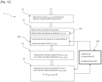
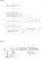
- FIG. 1A schematically represents a method of estimating 1 of an estimated position ⁇ of a rotor 31 of main machine 3 within the last two stages of a rotating electric machine 2 composed of the main machine 3, an exciter 4 and 'an estimation device 100, represented in Figure 1B , of the position of a rotor of a synchronous electric machine.
- the two filtered signals i ⁇ h ; i ⁇ h having an amplitude A, can be written in the form: i ⁇ h i ⁇ h ⁇ HAS cos ⁇ sin ⁇ sin 2 ⁇ ex t + ⁇
- the observed demodulation consists of eliminating the term sin(2 ⁇ ex t + ⁇ ) from equation (1).
- Equation (1) One way to achieve demodulation is to multiply equation (1) by a signal that emulates the carrier signal. This signal must have the frequency and phase of the carrier. However, knowing that the carrier cannot be measured, the signal can be reconstructed from the measurement of the exciter current i ex .
- An example of simple processing of the excitation current for reconstruction of the carrier can be: sin 2 ⁇ ex t + ⁇ ⁇ ⁇ 4 i ex I ex ⁇ 1
- H F ( s ) Another filtering of the two demodulated signals i ⁇ obs , i ⁇ obs , representing the two filtered signals i ⁇ h ; i ⁇ h after having been demodulated, called H F ( s ) is then applied in order to obtain only the low frequency information.
- H F ( s ) Another filtering of the two demodulated signals i ⁇ obs , i ⁇ obs , representing the two filtered signals i ⁇ h ; i ⁇ h after having been demodulated, called H F ( s ) is then applied in order to obtain only the low frequency information.
- i ⁇ obs , i ⁇ obs H F s 2 i ⁇ h i ⁇ h sin 2 ⁇ ex t + ⁇ ⁇
- i ⁇ obs i ⁇ obs H F s 2 i ⁇ h i ⁇ h sin 2 ⁇ ex t + ⁇ ⁇ ⁇ HAS cos ⁇ sin ⁇
- the estimation method 1 can also include a step of estimating a speed ⁇ ⁇ ⁇ of the rotor 31 of the main machine 3 combined within the step 14 of obtaining the estimated position ⁇ .
- Speed ⁇ ⁇ ⁇ of the rotor 31 is the time derivative of the estimated position ⁇ of the rotor 31.
- the estimated position ⁇ during the obtaining step 14 can be carried out using a phase lock loop or an observer, for example a Luenberger type observer, taking into account takes into account, for example, the mechanical model of the machine.
- These algorithms minimize the estimation difference between the estimated position ⁇ , at the preceding iteration step, and the real position ⁇ .
- This estimation difference is obtained from the demodulated signals i ⁇ obs , i ⁇ obs and the estimated position ⁇ obtained at the preceding instant.
- These algorithms can be advantageously used for speed estimation ⁇ ⁇ ⁇ in addition to obtaining the estimated position ⁇ of the rotor 31.
- an observer or state observer is an extension of a model represented in the form of a state representation, i.e. a system dynamic, via parameters called state variables.
- a state representation i.e. a system dynamic
- an observer makes it possible to reconstruct the state of the observed model from the dynamic system and measurements of other quantities.
- This representation makes it possible to determine the state of the system at any future time by knowing the state at the initial time and the behavior of the state variables.
- an observer and advantageously a Luenberger type observer, within which among the state variables, we include the position and the speed of the system.
- the model can consider the dynamics of the resisting torque or other mechanical parameters measured or known to the user.
- the estimation method 1 of the position of the rotor 31 is an iterative method, that is to say that the estimation method 1 can be repeated periodically.
- the four successive steps of measurement 11 of the current i abc , determination and harmonic isolation 12, demodulation 13 of the two filtered signals i ⁇ h ; i ⁇ h and obtaining 14 the estimated position ⁇ can therefore be iterated several times so as to refine the estimated position ⁇ and to reduce the possible error between the real position ⁇ and the estimated position ⁇ of the rotor 31 of the machine main 3.
- FIG. 1B schematically represents the last two stages of the rotating electric machine 2 composed of the main machine 3, the exciter 4 coupled to the main machine 3 via a rotating three-phase rectifier 5 and an estimation device 100 for stationary or low speed operation.
- the device for estimating the position of the rotor 31 of the main machine 3 is composed of four mirror modules of the four stages of the estimation process 1.
- a measurement module 101 conditioning the measurement step 11, capable of measuring the current i abc coming from the stator 32 of the main machine 3 and, possibly, capable of measuring the current i ex coming from the stator 42 of the exciter 4. Also, the measurement module 101 also makes it possible to eliminate the noise measured at the same time as the current i abc .
- a harmonic determination and isolation module 102 making it possible to condition the harmonic determination and isolation step 12 presented previously.
- the harmonic determination and isolation module 102 generates two filtered signals i ⁇ h ; i ⁇ h from the noise-free current i abc obtained from the measurement module 101. More precisely, the harmonic determination and isolation module 102 makes it possible to transform current i abc into the stationary reference frame ( ⁇ , ⁇ ) by any transformation allowing to model a three-phase system such as a Clarke transformation or a Concordia transformation.
- a demodulation module 103 of the two filtered signals i ⁇ h ; i ⁇ h making it possible to obtain two demodulated signals i ⁇ obs , i ⁇ obs , conditions the demodulation step 13.
- the demodulation module 103 of the two filtered signals i ⁇ h ; i ⁇ h is capable of collecting the measurement of the current i ex of the stator 42 of the exciter 4 captured by the measurement module 101 in order to generate the two demodulated signals i ⁇ obs , i ⁇ obs representing information on the real position ⁇ of the rotor 31 of the main machine 3.
- the two demodulated signals i ⁇ obs , i ⁇ obs are then recovered by a module 104 for obtaining the estimated position ⁇ of the rotor 31 of the main machine 3.
- the module for obtaining 104 conditions the step 14 of obtaining the estimated position ⁇ of the rotor 31 of the main machine 3.
- the module 104 for obtaining the estimated position ⁇ is configured to determine, from the two demodulated signals i ⁇ obs , i ⁇ obs , the estimated position ⁇ of the rotor 31 by several means.
- the harmonic determination and isolation step 12 may include, instead of the step 12B of isolating the two quadrature signals i ⁇ ; i ⁇ , an isolation step with anticipatory action (or “feedforward” in English)12B', represented in Figure 1C , allowing the isolation of the two filtered signals i ⁇ h ; i ⁇ h while inducing a change in the frequency of the harmonics of interest.
- the isolation step with anticipatory action 12B' is preceded by a step 120' allowing the processing of the currently estimated speed ⁇ ⁇ ⁇ by the process. It should be noted that the estimated speed ⁇ ⁇ ⁇ corresponds to an estimate of the electrical frequency of the machine denoted f e .
- any means having the function of eliminating high frequency variations on the estimated speed ⁇ ⁇ ⁇ can be taken into consideration during step 120'.
- step 12B' allows a transformation of the two quadrature signals i ⁇ ; i ⁇ in filtered signals i ⁇ h ; i ⁇ h from the phase of the filtered speed ⁇ f .
- this transformation is a Park transformation using the phase of the filtered speed ⁇ f determined during step 120'.
- the Park transformation has the advantage of allowing centering of the frequency of the harmonics by removing the term linked to the frequency f e of the main machine 3 if we consider f e ⁇ ⁇ ⁇ ⁇ f ⁇ 0 .
- the two filtered signals i ⁇ h ; i ⁇ h during the isolation step with anticipatory action 12B' form a pair of harmonics centered around the fundamental component whose frequency, freed from the phase shift linked to the frequency f e of the main machine 3, becomes: ⁇ not ⁇ f ex
- ⁇ f represents the integration of the filtered velocity ⁇ ⁇ ⁇ f .
- phase ⁇ of the carrier must be known precisely.
- an additional evaluation step 16 of the phase ⁇ of the carrier can be introduced into the estimation method 1. More precisely, the demodulation step 13 is preceded by the evaluation step 16 of the phase ⁇ of the carrier.
- This evaluation step 16 of the phase ⁇ of the carrier is illustrated below in Figure 2C .
- This phase ⁇ of the carrier is estimated from the pulsation ⁇ ex of the exciter 4, the estimated position ⁇ during a previous iteration of the estimation method 1 and the filtered signals i ⁇ h , i ⁇ h during the harmonic determination and isolation step 12.
- the carrier can be considered as a high frequency harmonic obtained at the rotor 41 of the exciter 4.
- the estimation method 1 of the estimated position ⁇ introduces a series of phase shifts on the estimated position ⁇ for each filter used.
- any filtering applied following demodulation step 13 induces a phase shift which cannot be ignored in the estimation method 1 because it is automatically transferred to the estimated position ⁇ .
- the estimation method 1 can include a correction step 18 of the estimated position ⁇ .
- This correction step 18 is applied following the step 14 of obtaining the estimated position ⁇ of the rotor 31 of the main machine 3 in order to correct the induced phase shift.
- ⁇ corr is the corrected position of the rotor 31 of the main machine 3 and ⁇ corr is a correction of the delays on the estimation of the position of the rotor 31 making it possible to align the estimated position ⁇ with the real position of the rotor 31 of the main machine 3.
- FIG. 2B represents the last two stages of the rotating electric machine 2 equipped with the estimation device 100 described in Figure 1B in its most complete version, that is to say including additional modules making it possible to condition the complete estimation method 1 described previously in Figure 2A .
- the estimation device 100 comprises the measurement module 101 of the current i abc coming from the stator 32 of the main machine 3, the harmonic determination and isolation module 102 of the two filtered signals i ⁇ h ; i ⁇ h from current i abc , from the demodulation module 103 of the two filtered signals i ⁇ h ; i ⁇ h and the module 104 for obtaining the estimated position ⁇ of the rotor 31.
- a correction module 106 of the estimated position ⁇ can be introduced.
- This correction module 106 which conditions the correction step 18 of the estimated position ⁇ , makes it possible to evaluate the corrected position ⁇ corr , which provides a more precise estimate of the position of the rotor 31 of the main machine 3.
- the estimation device 100 also includes an estimation module 105 of the phase ⁇ of the carrier.
- the estimation module 105 requires the corrected position ⁇ corr of the previous iteration as well as the two filtered signals i ⁇ h , i ⁇ h and the pulsation ⁇ ex of the exciter 4. Thanks to the Using these three parameters, the estimation module 105 provides the phase ⁇ of the carrier to the demodulation module 103. However, it may be possible to replace the estimated position ⁇ in place of the corrected position ⁇ corr in the case absence of correction step 18 of the estimated position ⁇ .
- the demodulation module 103 then collects the phase ⁇ evaluated by the estimation module 105 as well as the two signals i ⁇ h , i ⁇ h determined by the harmonic determination and isolation module 102, thus making it possible to pass from the measurement of the current i ex of the stator 42 of the exciter 4.
- the demodulation module 103 of the two filtered signals i ⁇ h ; i ⁇ h also makes it possible to obtain the two demodulated signals i ⁇ obs , i ⁇ obs from the pulsation carrier ⁇ ex of the exciter 4.
- an electrical machine comprising the exciter 4 and at least one main machine 3 can be equipped with the estimation device 100 in order to obtain the estimated position ⁇ or the corrected position ⁇ corr .
- FIG. 2C schematically represents the evaluation step 16 of the phase ⁇ of the carrier in order to allow the implementation of the demodulation step 13.
- the two filtered signals i ⁇ h , i ⁇ h , the pulsation ⁇ ex of the control of the The exciter 4 as well as the estimated position ⁇ of the rotor 31 of the main machine 3 are necessary.
- the estimated position ⁇ can be replaced by the corrected position ⁇ corr if this position is available in estimation method 1.
- a signal i d ⁇ h is obtained using the properties of the Clarke or Concordia transform combining the estimated position ⁇ of the rotor 31 and the two filtered signals i ⁇ h , i ⁇ h .
- the signal i d ⁇ h obtained is an estimate of the high frequency component aligned with the flux of the rotor 31 of the main machine 3.
- the signal i d ⁇ h obtained is an image of the carrier having the frequency and the phase of the signal induced at the level of the stator 32 of the main machine 3. It suffices to determine the phase of the signal at the frequency of interest, in a preferential case 2 ⁇ ex , to obtain the phase ⁇ .
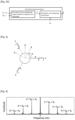
- FIG. 3 represents the possible transformations of the current i abc towards a rotating frame or a stationary frame.
- the rotating reference frame is defined by a first rotating axis d (direct) and a second rotating axis q (quadrature) centered at the level of the intersection of the three-phase current i a , i b , i c .
- the first rotating axis d and second rotating axis q undergo an angular variation linked to the position ⁇ used for the transformation.
- a transformation in a stationary frame composed of a first fixed axis ⁇ and a second fixed axis ⁇ is carried out, as stated previously, using the Clarke transformation or the Concordia transformation.
- the current i abc can be defined by a component along the first fixed axis ⁇ and by another component along the second fixed axis ⁇ , that is to say the two quadrature signals i ⁇ ; i ⁇ . Furthermore, it can be considered to use other types of transformation towards a stationary reference. Therefore, another stationary reference could be obtained with other pairs of quadrature signals.
- the frequency of the main harmonics is a combination of the operating frequency f ex of the exciter 4 or one of its multiples and the frequency f e of the main machine 3.
- the harmonics can have a frequency of the form f e ⁇ 2 * f ex or of the form f e ⁇ 4 * f ex or even of the form f e ⁇ 6 * f ex .
Landscapes
- Engineering & Computer Science (AREA)
- Power Engineering (AREA)
- Physics & Mathematics (AREA)
- Computer Hardware Design (AREA)
- Mathematical Physics (AREA)
- Control Of Motors That Do Not Use Commutators (AREA)
- Control Of Electric Motors In General (AREA)
- Control Of Ac Motors In General (AREA)
Claims (13)
- Verfahren zum Schätzen (1) der Position eines Rotors (31) einer elektrischen Synchronmaschine (3) ohne Signaleinspeisung, umfassend einen Rotor (31) und einen Stator (32), die mittels eines Gleichrichters (5) an eine invertierte elektrische Synchronmaschine (4), die einen Rotor (41) und einen Stator (42) umfasst, der als Erreger dient, gekoppelt ist, wobei der Gleichrichter (5) mit der Rotorerregung der Hauptmaschine (3) verbunden ist, wobei der Gleichrichter (5) mit dem Rotor (41) der invertierten elektrischen Synchronmaschine (4) für einen Stoppbetrieb oder einen Betrieb mit geringer Geschwindigkeit verbunden ist, wobei das Schätzverfahren (1) die folgenden Schritte umfasst:a. Messen (11) eines Stroms iabc, der in dem Stator (32) der elektrischen Synchronmaschine (3) zirkuliert;b. Bestimmen (12A) von zwei Quadratursignalen iα ; iβ gemäß einem feststehenden Bezugspunkt anhand des Stroms iabc und Isolieren (12B) von zwei gefilterten Signalen iαh ; iβh anhand der zwei Quadratursignale iα ; iβ ;c. Demodulieren (13) der zwei gefilterten Signale iαh ; iβh, um zwei demodulierte Signale iαobs, iβobs zu erhalten, wobei der Schritt des Demodulierens (13) der zwei gefilterten Signale iαh ; iβh eine Messung eines Stroms iex des Stators (42) der invertierten elektrischen Synchronmaschine (4) nutzt;d. Erhalten (14) einer geschätzten Position θ̂ des Rotors (31) anhand der zwei demodulierten Signale iαobs, iβobs.
- Schätzverfahren (1) nach Anspruch 1, wobei die geschätzte Position θ̂, die in dem Schritt d geschätzt wird, gemäß dem folgenden mathematischen Ausdruck erfolgt:

- Schätzverfahren (1) nach Anspruch 1, wobei die geschätzte Position θ̂ in dem Schritt d mit Hilfe eines Beobachters erfolgt.
- Schätzverfahren (1) nach einem der vorhergehenden Ansprüche, wobei die zwei gefilterten Signale iαh ; iβh eine Frequenz besitzen, die eine Betriebsfrequenz fex der invertierten elektrischen Synchronmaschine (4) und eine Frequenz fe der elektrischen Synchronmaschine (3) gemäß der folgenden Formel kombiniert:

- Schätzverfahren (1) nach einem der vorhergehenden Ansprüche, wobei das Isolieren (12B) der zwei gefilterten Signale iαh ; iβh anhand der zwei Quadratursignale iα ; iβ mit Hilfe eines Bandpassfilters oder eines Hochpassfilters erfolgt.
- Schätzverfahren (1) nach einem der vorhergehenden Ansprüchen, umfassend einen Schritt (17) zum Filtern der zwei demodulierten Signale iαobs, iβobs zwischen dem Schritt c und dem Schritt d, wobei der Filterschritt (17) mit Hilfe eines Bandpassfilters oder eines erweiterten Kalman-Filters erfolgt.
- Schätzverfahren (1) nach Anspruch 2, umfassend einen Schritt zum Schätzen der Geschwindigkeit Θ des Rotors (31) der elektrischen Synchronmaschine (3) anhand der geschätzten Position θ̂ des Rotors (31) der elektrischen Synchronmaschine (3).
- Schätzverfahren (1) nach Anspruch 7, umfassend einen Schritt zum Isolieren mit antizipativer Aktion (12B') der zwei gefilterten Signale iαh ; iβh anhand der zwei Quadratursignale iα ; iβ und einer Phase einer gefilterten Geschwindigkeit


- Schätzverfahren (1) nach einem der vorhergehenden Ansprüche, umfassend einen Schritt zum Korrigieren (18) der geschätzten Position θ̂ mit der folgenden mathematischen Formel:

- Schätzverfahren (1) nach dem vorhergehenden Anspruch, wobei die Korrektur der Verzögerungen φ̂corr die Summe einer Phasendifferenzkorrektur der in dem Schätzverfahren (1) verwendeten Filter φ̂F und einer Phasendifferenzkorrektur in Abhängigkeit von den elektromagnetischen Merkmalen der elektrischen Synchronmaschine φ̂LC ist.
- Schätzverfahren (1) nach einem der vorhergehenden Ansprüche, wobei das Schätzverfahren (1) periodisch wiederholt werden kann, wobei dem Schritt des Demodulierens (13) ein Schritt zum Auswerten (16) einer Phase φ̂ eines Trägers anhand der gefilterten Signale iαh ; iβ
h , einer Winkelfrequenz ωex der invertierten elektrischen Synchronmaschine (4) und der geschätzten Position θ̂ bei einer vorausgehenden Iteration des Schätzverfahrens (1) vorausgeht, wobei der Träger an dem Rotor (41) der invertierten elektrischen Synchronmaschine (4) erhalten wird. - Vorrichtung zum Schätzen (100) der Position eines Rotors (31) einer elektrischen Synchronmaschine (3) ohne Signaleinspeisung, umfassend einen Rotor (31) und einen Stator (32), die mittels eines Gleichrichters (5) an eine invertierte elektrische Synchronmaschine (4) gekoppelt ist, wobei die invertierte elektrische Synchronmaschine (4) einen Rotor (41) und einen Stator (42) umfasst, der als Erreger dient, wobei der Gleichrichter (5) mit der Rotorerregung der Hauptmaschine (3) verbunden ist, wobei der Gleichrichter (5) mit dem Rotor (41) der invertierten elektrischen Synchronmaschine (4) für einen Stoppbetrieb oder einen Betrieb mit geringer Geschwindigkeit verbunden ist, umfassend:a) ein Modul (101) zum Messen eines Stroms iabc, der in dem Stator (32) der elektrischen Synchronmaschine (3) zirkuliert;b) ein Modul (102) zum Bestimmen von zwei Quadratursignalen iα ; iβ gemäß einem feststehenden Bezugspunkt anhand des Stroms iabc und zum Isolieren von Harmonischen von zwei gefilterten Signalen iαh ; iβh anhand der zwei Quadratursignale iα ; iβ ;c) ein Modul (103) zum Demodulieren der zwei gefilterten Signale iαh ; iβh anhand einer Messung des Stroms iex des Stators (42) der invertierten elektrischen Synchronmaschine (4) oder eines Impulsträgers ωex der invertierten elektrischen Synchronmaschine (4), um zwei demodulierte Signale iαobs, iβobs zu erhalten,d) ein Empfangsmodul (104), das dafür konfiguriert ist, eine geschätzte Position θ̂ des Rotors (31) der elektrischen Synchronmaschine (3) anhand der zwei demodulierten Signale iαobs, iβobs zu bestimmen.
- Elektrische Maschine, umfassend eine invertierte elektrische Maschine (4) und mindestens eine elektrische Synchronmaschine (3), die mit der Schätzvorrichtung (100) nach Anspruch 12 ausgestattet ist.
Applications Claiming Priority (1)
| Application Number | Priority Date | Filing Date | Title |
|---|---|---|---|
| FR2011885A FR3116398B1 (fr) | 2020-11-19 | 2020-11-19 | Procédé d’estimation de la position d’un rotor de machine électrique synchrone. |
Publications (2)
| Publication Number | Publication Date |
|---|---|
| EP4002675A1 EP4002675A1 (de) | 2022-05-25 |
| EP4002675B1 true EP4002675B1 (de) | 2024-01-03 |
Family
ID=74206033
Family Applications (1)
| Application Number | Title | Priority Date | Filing Date |
|---|---|---|---|
| EP21208696.1A Active EP4002675B1 (de) | 2020-11-19 | 2021-11-17 | Verfahren und vorrichtung zur schätzung der rotorposition einer elektrischen synchronmaschine |
Country Status (3)
| Country | Link |
|---|---|
| US (1) | US11791755B2 (de) |
| EP (1) | EP4002675B1 (de) |
| FR (1) | FR3116398B1 (de) |
Families Citing this family (6)
| Publication number | Priority date | Publication date | Assignee | Title |
|---|---|---|---|---|
| FR3128337B1 (fr) * | 2021-10-19 | 2024-11-15 | Safran Electrical & Power | Commande d’une machine électrique tournante |
| CN115694292B (zh) * | 2022-11-07 | 2025-12-19 | 西北工业大学 | 一种多级式电机低速段转子位置估算方法 |
| CN115733405B (zh) * | 2022-11-07 | 2025-09-26 | 西北工业大学 | 基于低频旋转信号注入的多级式电机初始位置估算方法 |
| CN116191957B (zh) * | 2022-12-22 | 2025-12-19 | 西北工业大学 | 基于励磁信号正弦调制的多级式电机初始位置估算方法 |
| CN116667726B (zh) * | 2023-04-28 | 2024-06-07 | 浙江大学先进电气装备创新中心 | 一种基于n分法的永磁电机转子位置快速估计方法 |
| US12463571B2 (en) | 2023-04-28 | 2025-11-04 | Zhejian University Advanced Electrical Equipment Innovation Center | Fast rotor position estimation method for permanent magnet motor based on N-division approach |
Family Cites Families (7)
| Publication number | Priority date | Publication date | Assignee | Title |
|---|---|---|---|---|
| US7132816B1 (en) * | 2006-02-20 | 2006-11-07 | Hamilton Sundstrand Corporation | Brushless wound field synchronous machine rotor position tracking with exciter stator current harmonic tracking |
| EP2556381B1 (de) * | 2010-04-05 | 2014-05-07 | Hulusi Bulent Ertan | Drehzahl- und rotorpositionskalkulation bei elektromaschinen mit läufernut-oberschwingungen oder läufernut-oberschwingungen höherer ordnung |
| FR2974465B1 (fr) * | 2011-04-22 | 2016-09-30 | Sagem Defense Securite | Procede de detection d'une position angulaire d'un rotor de machine synchrone ; application a la mise en position et au maintien en position d'un rotor de machine synchrone, et a la commande d'un rotor de machine synchrone ; et dispositifs correspondants |
| US9998869B2 (en) | 2016-01-11 | 2018-06-12 | General Motors Llc | Determining vehicle location via signal strength and signal drop event |
| CN106059430B (zh) * | 2016-06-03 | 2018-08-24 | 南京航空航天大学 | 三级式无刷交流同步电机的转子位置估计方法 |
| CN107134962A (zh) * | 2017-05-23 | 2017-09-05 | 西北工业大学 | 一种三级式同步电机转子位置估算方法 |
| CN110855207B (zh) * | 2019-10-18 | 2020-10-27 | 西北工业大学 | 基于无信号注入的三级式电机低速段转子位置估算方法 |
-
2020
- 2020-11-19 FR FR2011885A patent/FR3116398B1/fr active Active
-
2021
- 2021-11-17 EP EP21208696.1A patent/EP4002675B1/de active Active
- 2021-11-17 US US17/529,167 patent/US11791755B2/en active Active
Also Published As
| Publication number | Publication date |
|---|---|
| FR3116398A1 (fr) | 2022-05-20 |
| US20220158577A1 (en) | 2022-05-19 |
| EP4002675A1 (de) | 2022-05-25 |
| US11791755B2 (en) | 2023-10-17 |
| FR3116398B1 (fr) | 2023-05-26 |
Similar Documents
| Publication | Publication Date | Title |
|---|---|---|
| EP4002675B1 (de) | Verfahren und vorrichtung zur schätzung der rotorposition einer elektrischen synchronmaschine | |
| EP2684289B1 (de) | In einem stromwandler implementiertes steuerverfahren zur identifizierung von parametern in bezug auf die magnetische sättigung eines elektromotors | |
| CA2745974C (fr) | Procede et systeme de correction d'un signal de mesure d'une temperature | |
| EP2246973B1 (de) | Verfahren zur Positionsbestimmung des Flussvektors eines Motors | |
| EP3658881B1 (de) | Verfahren und vorrichtung zur suche nach einem eine mechanische rotierende leistungsübertragungsvorrichtung beeinträchtigenden defekt | |
| CH694113A5 (fr) | Stabilisateur de réseau de distribution d'énergie et procédé de stabilisation de réseau de distruibution d'énergie. | |
| EP3287795A1 (de) | Bestimmung der frequenz eines wechselsignals | |
| FR2549966A1 (fr) | Filtre explorateur pour detecter la teneur en courant continu d'une courbe de courant alternatif | |
| FR2897729A1 (fr) | Estimation amelioree de la position angulaire et de la vitesse pour machines synchrones sur la base d'un flux rotorique etendu. | |
| EP3221958B1 (de) | Verfahren zur steuerung einer elektrischen synchronmaschine mit einem gewickelten rotor | |
| EP4104024B1 (de) | Messung der übertragungsfunktion in einem mechatronischen system | |
| EP3560095B1 (de) | Verfahren zum bestimmen einer direktachseninduktivität und einer quadraturachseninduktivität einer elektrischen maschine, entsprechendes computerprogramm und vorrichtung | |
| EP3785000B1 (de) | Verfahren und system zur verarbeitung eines von einem sensor gelieferten temperaturmesssignals | |
| FR3097090A1 (fr) | Procédé d’estimation du couple électromagnétique d’une machine électrique synchrone | |
| EP3853994B1 (de) | Verfahren zur bestimmung des magnetischen durchflusses einer elektromaschine | |
| WO2023062167A1 (fr) | Procédé d'estimation de la position et de la vitesse du rotor d'une machine électrique synchrone à aimant permanent | |
| FR3075512A1 (fr) | Procede de commande d'un moteur electrique incluant une sequence d'identification d'un transformateur | |
| EP4101065A1 (de) | Verfahren zur schätzung des elektomagnetischen drehmoments einer elektrischen synchronmaschine | |
| EP3534478A1 (de) | Frequenz- und phasenschätzung | |
| FR3072516B1 (fr) | Dispositif de charge d'une batterie d'accumulation electrique | |
| EP3314742B1 (de) | Steuerung einer elektrischen synchronmaschine mit einem gewickelten rotor | |
| WO2018077896A1 (fr) | Procedes et dispositifs relatifs a l'estimation d'une position angulaire d'un rotor | |
| WO2015121049A2 (fr) | Procede de commande d'une machine electrique a aimant permanent optimisant les pertes joule | |
| FR2921212A1 (fr) | Demarreur/generatrice muni d'un indicateur de position de generatrice a aimants permanents |
Legal Events
| Date | Code | Title | Description |
|---|---|---|---|
| PUAI | Public reference made under article 153(3) epc to a published international application that has entered the european phase |
Free format text: ORIGINAL CODE: 0009012 |
|
| STAA | Information on the status of an ep patent application or granted ep patent |
Free format text: STATUS: THE APPLICATION HAS BEEN PUBLISHED |
|
| AK | Designated contracting states |
Kind code of ref document: A1 Designated state(s): AL AT BE BG CH CY CZ DE DK EE ES FI FR GB GR HR HU IE IS IT LI LT LU LV MC MK MT NL NO PL PT RO RS SE SI SK SM TR |
|
| STAA | Information on the status of an ep patent application or granted ep patent |
Free format text: STATUS: REQUEST FOR EXAMINATION WAS MADE |
|
| 17P | Request for examination filed |
Effective date: 20221124 |
|
| RBV | Designated contracting states (corrected) |
Designated state(s): AL AT BE BG CH CY CZ DE DK EE ES FI FR GB GR HR HU IE IS IT LI LT LU LV MC MK MT NL NO PL PT RO RS SE SI SK SM TR |
|
| GRAP | Despatch of communication of intention to grant a patent |
Free format text: ORIGINAL CODE: EPIDOSNIGR1 |
|
| STAA | Information on the status of an ep patent application or granted ep patent |
Free format text: STATUS: GRANT OF PATENT IS INTENDED |
|
| RIC1 | Information provided on ipc code assigned before grant |
Ipc: B64D 27/00 20060101ALN20230922BHEP Ipc: H02P 25/03 20160101ALI20230922BHEP Ipc: H02P 23/14 20060101ALI20230922BHEP Ipc: H02P 23/12 20060101ALI20230922BHEP Ipc: H02P 23/03 20060101ALI20230922BHEP Ipc: H02P 21/18 20160101ALI20230922BHEP Ipc: H02P 21/13 20060101ALI20230922BHEP Ipc: H02P 21/04 20060101ALI20230922BHEP Ipc: H02P 6/18 20160101ALI20230922BHEP Ipc: H02P 6/17 20160101ALI20230922BHEP Ipc: H02P 6/16 20160101ALI20230922BHEP Ipc: H02P 5/46 20060101ALI20230922BHEP Ipc: H02P 1/04 20060101AFI20230922BHEP |
|
| INTG | Intention to grant announced |
Effective date: 20231023 |
|
| GRAS | Grant fee paid |
Free format text: ORIGINAL CODE: EPIDOSNIGR3 |
|
| GRAA | (expected) grant |
Free format text: ORIGINAL CODE: 0009210 |
|
| STAA | Information on the status of an ep patent application or granted ep patent |
Free format text: STATUS: THE PATENT HAS BEEN GRANTED |
|
| AK | Designated contracting states |
Kind code of ref document: B1 Designated state(s): AL AT BE BG CH CY CZ DE DK EE ES FI FR GB GR HR HU IE IS IT LI LT LU LV MC MK MT NL NO PL PT RO RS SE SI SK SM TR |
|
| REG | Reference to a national code |
Ref country code: GB Ref legal event code: FG4D Free format text: NOT ENGLISH |
|
| REG | Reference to a national code |
Ref country code: DE Ref legal event code: R096 Ref document number: 602021008302 Country of ref document: DE |
|
| REG | Reference to a national code |
Ref country code: CH Ref legal event code: EP |
|
| REG | Reference to a national code |
Ref country code: IE Ref legal event code: FG4D Free format text: LANGUAGE OF EP DOCUMENT: FRENCH |
|
| REG | Reference to a national code |
Ref country code: LT Ref legal event code: MG9D |
|
| PG25 | Lapsed in a contracting state [announced via postgrant information from national office to epo] |
Ref country code: ES Free format text: LAPSE BECAUSE OF FAILURE TO SUBMIT A TRANSLATION OF THE DESCRIPTION OR TO PAY THE FEE WITHIN THE PRESCRIBED TIME-LIMIT Effective date: 20240103 |
|
| PG25 | Lapsed in a contracting state [announced via postgrant information from national office to epo] |
Ref country code: ES Free format text: LAPSE BECAUSE OF FAILURE TO SUBMIT A TRANSLATION OF THE DESCRIPTION OR TO PAY THE FEE WITHIN THE PRESCRIBED TIME-LIMIT Effective date: 20240103 |
|
| REG | Reference to a national code |
Ref country code: NL Ref legal event code: MP Effective date: 20240103 |
|
| REG | Reference to a national code |
Ref country code: AT Ref legal event code: MK05 Ref document number: 1647809 Country of ref document: AT Kind code of ref document: T Effective date: 20240103 |
|
| PG25 | Lapsed in a contracting state [announced via postgrant information from national office to epo] |
Ref country code: NL Free format text: LAPSE BECAUSE OF FAILURE TO SUBMIT A TRANSLATION OF THE DESCRIPTION OR TO PAY THE FEE WITHIN THE PRESCRIBED TIME-LIMIT Effective date: 20240103 |
|
| PG25 | Lapsed in a contracting state [announced via postgrant information from national office to epo] |
Ref country code: NL Free format text: LAPSE BECAUSE OF FAILURE TO SUBMIT A TRANSLATION OF THE DESCRIPTION OR TO PAY THE FEE WITHIN THE PRESCRIBED TIME-LIMIT Effective date: 20240103 |
|
| PG25 | Lapsed in a contracting state [announced via postgrant information from national office to epo] |
Ref country code: IS Free format text: LAPSE BECAUSE OF FAILURE TO SUBMIT A TRANSLATION OF THE DESCRIPTION OR TO PAY THE FEE WITHIN THE PRESCRIBED TIME-LIMIT Effective date: 20240503 |
|
| PG25 | Lapsed in a contracting state [announced via postgrant information from national office to epo] |
Ref country code: LT Free format text: LAPSE BECAUSE OF FAILURE TO SUBMIT A TRANSLATION OF THE DESCRIPTION OR TO PAY THE FEE WITHIN THE PRESCRIBED TIME-LIMIT Effective date: 20240103 |
|
| PG25 | Lapsed in a contracting state [announced via postgrant information from national office to epo] |
Ref country code: GR Free format text: LAPSE BECAUSE OF FAILURE TO SUBMIT A TRANSLATION OF THE DESCRIPTION OR TO PAY THE FEE WITHIN THE PRESCRIBED TIME-LIMIT Effective date: 20240404 |
|
| PG25 | Lapsed in a contracting state [announced via postgrant information from national office to epo] |
Ref country code: HR Free format text: LAPSE BECAUSE OF FAILURE TO SUBMIT A TRANSLATION OF THE DESCRIPTION OR TO PAY THE FEE WITHIN THE PRESCRIBED TIME-LIMIT Effective date: 20240103 Ref country code: RS Free format text: LAPSE BECAUSE OF FAILURE TO SUBMIT A TRANSLATION OF THE DESCRIPTION OR TO PAY THE FEE WITHIN THE PRESCRIBED TIME-LIMIT Effective date: 20240403 |
|
| PG25 | Lapsed in a contracting state [announced via postgrant information from national office to epo] |
Ref country code: CZ Free format text: LAPSE BECAUSE OF FAILURE TO SUBMIT A TRANSLATION OF THE DESCRIPTION OR TO PAY THE FEE WITHIN THE PRESCRIBED TIME-LIMIT Effective date: 20240103 Ref country code: AT Free format text: LAPSE BECAUSE OF FAILURE TO SUBMIT A TRANSLATION OF THE DESCRIPTION OR TO PAY THE FEE WITHIN THE PRESCRIBED TIME-LIMIT Effective date: 20240103 |
|
| PG25 | Lapsed in a contracting state [announced via postgrant information from national office to epo] |
Ref country code: RS Free format text: LAPSE BECAUSE OF FAILURE TO SUBMIT A TRANSLATION OF THE DESCRIPTION OR TO PAY THE FEE WITHIN THE PRESCRIBED TIME-LIMIT Effective date: 20240403 Ref country code: NO Free format text: LAPSE BECAUSE OF FAILURE TO SUBMIT A TRANSLATION OF THE DESCRIPTION OR TO PAY THE FEE WITHIN THE PRESCRIBED TIME-LIMIT Effective date: 20240403 Ref country code: LT Free format text: LAPSE BECAUSE OF FAILURE TO SUBMIT A TRANSLATION OF THE DESCRIPTION OR TO PAY THE FEE WITHIN THE PRESCRIBED TIME-LIMIT Effective date: 20240103 Ref country code: IS Free format text: LAPSE BECAUSE OF FAILURE TO SUBMIT A TRANSLATION OF THE DESCRIPTION OR TO PAY THE FEE WITHIN THE PRESCRIBED TIME-LIMIT Effective date: 20240503 Ref country code: HR Free format text: LAPSE BECAUSE OF FAILURE TO SUBMIT A TRANSLATION OF THE DESCRIPTION OR TO PAY THE FEE WITHIN THE PRESCRIBED TIME-LIMIT Effective date: 20240103 Ref country code: GR Free format text: LAPSE BECAUSE OF FAILURE TO SUBMIT A TRANSLATION OF THE DESCRIPTION OR TO PAY THE FEE WITHIN THE PRESCRIBED TIME-LIMIT Effective date: 20240404 Ref country code: CZ Free format text: LAPSE BECAUSE OF FAILURE TO SUBMIT A TRANSLATION OF THE DESCRIPTION OR TO PAY THE FEE WITHIN THE PRESCRIBED TIME-LIMIT Effective date: 20240103 Ref country code: BG Free format text: LAPSE BECAUSE OF FAILURE TO SUBMIT A TRANSLATION OF THE DESCRIPTION OR TO PAY THE FEE WITHIN THE PRESCRIBED TIME-LIMIT Effective date: 20240103 Ref country code: AT Free format text: LAPSE BECAUSE OF FAILURE TO SUBMIT A TRANSLATION OF THE DESCRIPTION OR TO PAY THE FEE WITHIN THE PRESCRIBED TIME-LIMIT Effective date: 20240103 |
|
| PG25 | Lapsed in a contracting state [announced via postgrant information from national office to epo] |
Ref country code: PT Free format text: LAPSE BECAUSE OF FAILURE TO SUBMIT A TRANSLATION OF THE DESCRIPTION OR TO PAY THE FEE WITHIN THE PRESCRIBED TIME-LIMIT Effective date: 20240503 Ref country code: PL Free format text: LAPSE BECAUSE OF FAILURE TO SUBMIT A TRANSLATION OF THE DESCRIPTION OR TO PAY THE FEE WITHIN THE PRESCRIBED TIME-LIMIT Effective date: 20240103 |
|
| RAP2 | Party data changed (patent owner data changed or rights of a patent transferred) |
Owner name: SAFRAN ELECTRICAL & POWER |
|
| PG25 | Lapsed in a contracting state [announced via postgrant information from national office to epo] |
Ref country code: SE Free format text: LAPSE BECAUSE OF FAILURE TO SUBMIT A TRANSLATION OF THE DESCRIPTION OR TO PAY THE FEE WITHIN THE PRESCRIBED TIME-LIMIT Effective date: 20240103 Ref country code: PT Free format text: LAPSE BECAUSE OF FAILURE TO SUBMIT A TRANSLATION OF THE DESCRIPTION OR TO PAY THE FEE WITHIN THE PRESCRIBED TIME-LIMIT Effective date: 20240503 Ref country code: PL Free format text: LAPSE BECAUSE OF FAILURE TO SUBMIT A TRANSLATION OF THE DESCRIPTION OR TO PAY THE FEE WITHIN THE PRESCRIBED TIME-LIMIT Effective date: 20240103 Ref country code: LV Free format text: LAPSE BECAUSE OF FAILURE TO SUBMIT A TRANSLATION OF THE DESCRIPTION OR TO PAY THE FEE WITHIN THE PRESCRIBED TIME-LIMIT Effective date: 20240103 |
|
| REG | Reference to a national code |
Ref country code: DE Ref legal event code: R097 Ref document number: 602021008302 Country of ref document: DE |
|
| PG25 | Lapsed in a contracting state [announced via postgrant information from national office to epo] |
Ref country code: DK Free format text: LAPSE BECAUSE OF FAILURE TO SUBMIT A TRANSLATION OF THE DESCRIPTION OR TO PAY THE FEE WITHIN THE PRESCRIBED TIME-LIMIT Effective date: 20240103 |
|
| PG25 | Lapsed in a contracting state [announced via postgrant information from national office to epo] |
Ref country code: SM Free format text: LAPSE BECAUSE OF FAILURE TO SUBMIT A TRANSLATION OF THE DESCRIPTION OR TO PAY THE FEE WITHIN THE PRESCRIBED TIME-LIMIT Effective date: 20240103 |
|
| PG25 | Lapsed in a contracting state [announced via postgrant information from national office to epo] |
Ref country code: EE Free format text: LAPSE BECAUSE OF FAILURE TO SUBMIT A TRANSLATION OF THE DESCRIPTION OR TO PAY THE FEE WITHIN THE PRESCRIBED TIME-LIMIT Effective date: 20240103 |
|
| PG25 | Lapsed in a contracting state [announced via postgrant information from national office to epo] |
Ref country code: SK Free format text: LAPSE BECAUSE OF FAILURE TO SUBMIT A TRANSLATION OF THE DESCRIPTION OR TO PAY THE FEE WITHIN THE PRESCRIBED TIME-LIMIT Effective date: 20240103 |
|
| PG25 | Lapsed in a contracting state [announced via postgrant information from national office to epo] |
Ref country code: SM Free format text: LAPSE BECAUSE OF FAILURE TO SUBMIT A TRANSLATION OF THE DESCRIPTION OR TO PAY THE FEE WITHIN THE PRESCRIBED TIME-LIMIT Effective date: 20240103 Ref country code: SK Free format text: LAPSE BECAUSE OF FAILURE TO SUBMIT A TRANSLATION OF THE DESCRIPTION OR TO PAY THE FEE WITHIN THE PRESCRIBED TIME-LIMIT Effective date: 20240103 Ref country code: RO Free format text: LAPSE BECAUSE OF FAILURE TO SUBMIT A TRANSLATION OF THE DESCRIPTION OR TO PAY THE FEE WITHIN THE PRESCRIBED TIME-LIMIT Effective date: 20240103 Ref country code: EE Free format text: LAPSE BECAUSE OF FAILURE TO SUBMIT A TRANSLATION OF THE DESCRIPTION OR TO PAY THE FEE WITHIN THE PRESCRIBED TIME-LIMIT Effective date: 20240103 Ref country code: DK Free format text: LAPSE BECAUSE OF FAILURE TO SUBMIT A TRANSLATION OF THE DESCRIPTION OR TO PAY THE FEE WITHIN THE PRESCRIBED TIME-LIMIT Effective date: 20240103 |
|
| PLBE | No opposition filed within time limit |
Free format text: ORIGINAL CODE: 0009261 |
|
| STAA | Information on the status of an ep patent application or granted ep patent |
Free format text: STATUS: NO OPPOSITION FILED WITHIN TIME LIMIT |
|
| PG25 | Lapsed in a contracting state [announced via postgrant information from national office to epo] |
Ref country code: IT Free format text: LAPSE BECAUSE OF FAILURE TO SUBMIT A TRANSLATION OF THE DESCRIPTION OR TO PAY THE FEE WITHIN THE PRESCRIBED TIME-LIMIT Effective date: 20240103 |
|
| 26N | No opposition filed |
Effective date: 20241007 |
|
| PG25 | Lapsed in a contracting state [announced via postgrant information from national office to epo] |
Ref country code: IT Free format text: LAPSE BECAUSE OF FAILURE TO SUBMIT A TRANSLATION OF THE DESCRIPTION OR TO PAY THE FEE WITHIN THE PRESCRIBED TIME-LIMIT Effective date: 20240103 |
|
| PG25 | Lapsed in a contracting state [announced via postgrant information from national office to epo] |
Ref country code: SI Free format text: LAPSE BECAUSE OF FAILURE TO SUBMIT A TRANSLATION OF THE DESCRIPTION OR TO PAY THE FEE WITHIN THE PRESCRIBED TIME-LIMIT Effective date: 20240103 |
|
| REG | Reference to a national code |
Ref country code: CH Ref legal event code: PL |
|
| PG25 | Lapsed in a contracting state [announced via postgrant information from national office to epo] |
Ref country code: MC Free format text: LAPSE BECAUSE OF FAILURE TO SUBMIT A TRANSLATION OF THE DESCRIPTION OR TO PAY THE FEE WITHIN THE PRESCRIBED TIME-LIMIT Effective date: 20240103 |
|
| PG25 | Lapsed in a contracting state [announced via postgrant information from national office to epo] |
Ref country code: LU Free format text: LAPSE BECAUSE OF NON-PAYMENT OF DUE FEES Effective date: 20241117 |
|
| REG | Reference to a national code |
Ref country code: CH Ref legal event code: PL |
|
| PG25 | Lapsed in a contracting state [announced via postgrant information from national office to epo] |
Ref country code: CH Free format text: LAPSE BECAUSE OF NON-PAYMENT OF DUE FEES Effective date: 20241130 |
|
| REG | Reference to a national code |
Ref country code: BE Ref legal event code: MM Effective date: 20241130 |
|
| PG25 | Lapsed in a contracting state [announced via postgrant information from national office to epo] |
Ref country code: FI Free format text: LAPSE BECAUSE OF FAILURE TO SUBMIT A TRANSLATION OF THE DESCRIPTION OR TO PAY THE FEE WITHIN THE PRESCRIBED TIME-LIMIT Effective date: 20240103 |
|
| PG25 | Lapsed in a contracting state [announced via postgrant information from national office to epo] |
Ref country code: BE Free format text: LAPSE BECAUSE OF NON-PAYMENT OF DUE FEES Effective date: 20241130 |
|
| PG25 | Lapsed in a contracting state [announced via postgrant information from national office to epo] |
Ref country code: IE Free format text: LAPSE BECAUSE OF NON-PAYMENT OF DUE FEES Effective date: 20241117 |
|
| PGFP | Annual fee paid to national office [announced via postgrant information from national office to epo] |
Ref country code: DE Payment date: 20251118 Year of fee payment: 5 |
|
| PGFP | Annual fee paid to national office [announced via postgrant information from national office to epo] |
Ref country code: GB Payment date: 20251125 Year of fee payment: 5 |
|
| PGFP | Annual fee paid to national office [announced via postgrant information from national office to epo] |
Ref country code: FR Payment date: 20251125 Year of fee payment: 5 |
|
| PG25 | Lapsed in a contracting state [announced via postgrant information from national office to epo] |
Ref country code: HU Free format text: LAPSE BECAUSE OF FAILURE TO SUBMIT A TRANSLATION OF THE DESCRIPTION OR TO PAY THE FEE WITHIN THE PRESCRIBED TIME-LIMIT; INVALID AB INITIO Effective date: 20211117 |
|
| PG25 | Lapsed in a contracting state [announced via postgrant information from national office to epo] |
Ref country code: CY Free format text: LAPSE BECAUSE OF FAILURE TO SUBMIT A TRANSLATION OF THE DESCRIPTION OR TO PAY THE FEE WITHIN THE PRESCRIBED TIME-LIMIT; INVALID AB INITIO Effective date: 20211117 |