EP4002749B1 - Distribution de clé quantique variable en continu - Google Patents
Distribution de clé quantique variable en continu Download PDFInfo
- Publication number
- EP4002749B1 EP4002749B1 EP20306420.9A EP20306420A EP4002749B1 EP 4002749 B1 EP4002749 B1 EP 4002749B1 EP 20306420 A EP20306420 A EP 20306420A EP 4002749 B1 EP4002749 B1 EP 4002749B1
- Authority
- EP
- European Patent Office
- Prior art keywords
- symbols
- qkd
- matrix
- applying
- pilot
- Prior art date
- Legal status (The legal status is an assumption and is not a legal conclusion. Google has not performed a legal analysis and makes no representation as to the accuracy of the status listed.)
- Active
Links
Images





Classifications
-
- H—ELECTRICITY
- H04—ELECTRIC COMMUNICATION TECHNIQUE
- H04L—TRANSMISSION OF DIGITAL INFORMATION, e.g. TELEGRAPHIC COMMUNICATION
- H04L9/00—Cryptographic mechanisms or cryptographic arrangements for secret or secure communications; Network security protocols
- H04L9/08—Key distribution or management, e.g. generation, sharing or updating, of cryptographic keys or passwords
- H04L9/0816—Key establishment, i.e. cryptographic processes or cryptographic protocols whereby a shared secret becomes available to two or more parties, for subsequent use
- H04L9/0852—Quantum cryptography
- H04L9/0855—Quantum cryptography involving additional nodes, e.g. quantum relays, repeaters, intermediate nodes or remote nodes
-
- G—PHYSICS
- G06—COMPUTING OR CALCULATING; COUNTING
- G06F—ELECTRIC DIGITAL DATA PROCESSING
- G06F17/00—Digital computing or data processing equipment or methods, specially adapted for specific functions
- G06F17/10—Complex mathematical operations
- G06F17/16—Matrix or vector computation, e.g. matrix-matrix or matrix-vector multiplication, matrix factorization
-
- G—PHYSICS
- G06—COMPUTING OR CALCULATING; COUNTING
- G06F—ELECTRIC DIGITAL DATA PROCESSING
- G06F17/00—Digital computing or data processing equipment or methods, specially adapted for specific functions
- G06F17/10—Complex mathematical operations
- G06F17/17—Function evaluation by approximation methods, e.g. inter- or extrapolation, smoothing, least mean square method
-
- H—ELECTRICITY
- H04—ELECTRIC COMMUNICATION TECHNIQUE
- H04L—TRANSMISSION OF DIGITAL INFORMATION, e.g. TELEGRAPHIC COMMUNICATION
- H04L9/00—Cryptographic mechanisms or cryptographic arrangements for secret or secure communications; Network security protocols
- H04L9/06—Cryptographic mechanisms or cryptographic arrangements for secret or secure communications; Network security protocols the encryption apparatus using shift registers or memories for block-wise or stream coding, e.g. DES systems or RC4; Hash functions; Pseudorandom sequence generators
- H04L9/065—Encryption by serially and continuously modifying data stream elements, e.g. stream cipher systems, RC4, SEAL or A5/3
- H04L9/0656—Pseudorandom key sequence combined element-for-element with data sequence, e.g. one-time-pad [OTP] or Vernam's cipher
- H04L9/0662—Pseudorandom key sequence combined element-for-element with data sequence, e.g. one-time-pad [OTP] or Vernam's cipher with particular pseudorandom sequence generator
-
- H—ELECTRICITY
- H04—ELECTRIC COMMUNICATION TECHNIQUE
- H04L—TRANSMISSION OF DIGITAL INFORMATION, e.g. TELEGRAPHIC COMMUNICATION
- H04L9/00—Cryptographic mechanisms or cryptographic arrangements for secret or secure communications; Network security protocols
- H04L9/08—Key distribution or management, e.g. generation, sharing or updating, of cryptographic keys or passwords
- H04L9/0816—Key establishment, i.e. cryptographic processes or cryptographic protocols whereby a shared secret becomes available to two or more parties, for subsequent use
- H04L9/0819—Key transport or distribution, i.e. key establishment techniques where one party creates or otherwise obtains a secret value, and securely transfers it to the other(s)
- H04L9/0825—Key transport or distribution, i.e. key establishment techniques where one party creates or otherwise obtains a secret value, and securely transfers it to the other(s) using asymmetric-key encryption or public key infrastructure [PKI], e.g. key signature or public key certificates
-
- H—ELECTRICITY
- H04—ELECTRIC COMMUNICATION TECHNIQUE
- H04L—TRANSMISSION OF DIGITAL INFORMATION, e.g. TELEGRAPHIC COMMUNICATION
- H04L9/00—Cryptographic mechanisms or cryptographic arrangements for secret or secure communications; Network security protocols
- H04L9/08—Key distribution or management, e.g. generation, sharing or updating, of cryptographic keys or passwords
- H04L9/0816—Key establishment, i.e. cryptographic processes or cryptographic protocols whereby a shared secret becomes available to two or more parties, for subsequent use
- H04L9/0852—Quantum cryptography
- H04L9/0858—Details about key distillation or coding, e.g. reconciliation, error correction, privacy amplification, polarisation coding or phase coding
Definitions
- Various example embodiments relate generally to method and apparatuses for continuous variable quantum key distribution (CV-QKD).
- Quantum Key Distribution is a secure communication method taking advantage of Heisenberg uncertainty principle.
- the general framework is the following: Alice (sender side) and Bob (receiver side) are willing to produce a shared random key that will serve to generate a secret key in a cryptographic protocol such as the one-time pad. In order to do so they will communicate random data on an unsecure quantum channel such as an optical fibre.
- a third party call her Eve
- wants to eavesdrop on the quantum signal then Eve must perform a measurement that will disrupt the channel.
- Alice and Bob can evaluate this disturbance and estimate the quantity of information obtained by Eve, e.g. by detecting on receiver side an increase of the variance of the noise.
- Alice and Bob can extract or generate a secret key from at least a portion of the shared random key left untouched by Eve: the secret key may therefore be shorter than the shared random key transmitted by Alice.
- This extraction process may be monitored by communicating on a second classical channel. This classical monitoring channel is assumed to be an authenticated channel.
- US 2016/204894 A1 discloses an optical transport system configured to transport data using a PDM modulation format.
- an apparatus for random key transmission comprises:
- the apparatus further comprises a power attenuator configured to adjust the variance of the power of the modulated optical signal.
- an apparatus for random key decoding comprises means for
- applying the polarization correction includes determining a rotation matrix in a Stokes space representing a polarization impairment, determining an inverse matrix of a Jones matrix corresponding to the rotation matrix and applying in a Jones space the inverse matrix to vectors representing the input symbols.
- determining the rotation matrix includes:
- determining the inverse matrix includes :
- applying the carrier phase correction includes applying a Kalman filter to the corrected pilot symbols obtained from corresponding pilot symbols to estimate phase noise values for the corresponding pilot symbols and estimating a phase noise value for a QKD symbol by applying a linear interpolation to phase noise values estimated for at least a first pilot symbol and at least one second pilot symbol between which the QKD symbol is temporally interleaved.
- the apparatus further comprises a laser coupled to a coherent receiver circuit for receiving and extracting the symbols from a modulated optical signal.
- a method for random key decoding comprises:
- Applying the polarization correction may include determining a rotation matrix in a Stokes space representing a polarization impairment based at least on the pilot symbols, determining an inverse matrix of a Jones matrix corresponding to the rotation matrix and applying in a Jones space the inverse matrix to vectors representing the QKD symbols.
- Determining the rotation matrix may include:
- Determining the inverse matrix may include:
- Applying the carrier phase correction may include applying a Kalman filter to the corrected pilot symbols obtained from corresponding pilot symbols to estimate respective phase noise values for the corresponding pilot symbols and estimating a phase noise value for a QKD symbol by applying a linear interpolation to phase noise values estimated for at least a first pilot symbol and at least one second pilot symbol between which the QKD symbol is temporally interleaved.
- an apparatus comprising at least one processor and at least one memory including computer program code.
- the at least one memory and the computer program code are configured to, with the at least one processor, cause the apparatus to perform one or more or all steps of a method for random key decoding as disclosed therein.
- the apparatus comprises means for performing one or more or all steps of a method for random key decoding as disclosed herein.
- the means may include circuitry configured to perform one or more or all steps of the method for random key decoding as disclosed herein.
- the means may include at least one processor and at least one memory including computer program code, wherein the at least one memory and the computer program code are configured to, with the at least one processor, cause the apparatus to perform one or more or all steps of the method for random key decoding as disclosed herein.
- At least one example embodiment provides a non-transitory computer-readable medium storing computer-executable instructions that, when executed by at least one processor at an apparatus, causes the apparatus to perform a method for random key decoding as disclosed therein.
- the computer-executable instructions cause the apparatus to perform one or more or all steps of a method for random key decoding as disclosed herein.
- a coherent transceiver apparatus using a QAM-based PCS modulation is used in conjunction with corresponding DSP suite for implementing CV-QKD.
- the random data to be shared between Alice and Bob is encoded in the quadratures (I and Q values) of the electric field of light pulses produced by a laser.
- the I and Q quadratures are the Cartesian (orthogonal) components of the quantized electric field: to a couple of values representing the amplitude and phase correspond a couple of values of the orthogonal components.
- Alice modulates randomly the amplitude and phase of the signal produced by the laser, with a given distribution defined by a QAM-based PCS constellation map.
- PCS Probabilistic constellation shaping
- QAM-based PCS uses a base modulation format which is a quadrature amplitude modulation (QAM) format, for example a square QAM such as 16QAM and 64QAM and changes the probability of the occurrence of constellation points.
- QAM quadrature amplitude modulation
- PCS enables fine rate adaptation and generation of a signal close to the optimum Gaussian distribution for a linear channel.
- the probability distribution is here the Maxwell-Boltzmann function.
- the PCS probability distribution may be realized by an algorithm implemented by a computer or circuitry, called here distribution matcher, which receives as input long blocks of binary random information bits, and uses source coding techniques, such that the frequency of occurrence of symbols in the corresponding output block correspond to the probability given by the target probability distribution, which is here the Maxwell-Boltzmann function. See for example the document by Georg Böcherer et al, entitled “ Probabilistic Shaping and Forward Error Correction for Fiber-Optic Communication Systems", Journal of Lightwave Technology, Vol. 37, Issue 2, pp. 230-244, (2019 ).
- the quadrature values act like the position and momentum of a particle (e.g. photon) that, according to the Heisenberg principle, cannot be simultaneously and precisely determined by Eve.
- the uncertainty principle applies hence to any measurement performed by Eve on any of the two quadratures and guarantees that an increase in the variance observed by Bob is produced.
- Alice and Bob can track this increase of variance back to the quality of Eve's measurement.
- the information theory developed by Shannon during the war may be used.
- the Shannon theory makes the link between this variance and the quantity of information obtained by Eve.
- the GG02 protocol defined by Grosshans and Grangier cited in introduction, using ordinary lasers and homodyne detections, may be used with this respect.
- the apparatus at sender side is a CVQKD setup based on a Gaussian-like version of a QAM modulation, here QAM-based PCS used to send the shared random data (also referred to herein as the QKD signal).
- QAM-based PCS used to send the shared random data
- This type of modulation enables approaching the Shannon capacity.
- QPSK modulation see for example D. Milovan ⁇ ev et al., "Spectrally-Shaped Continuous-Variable QKD Operating at 500 MHz Over an Optical Pipe Lit by 11 DWDM Channels", in Optical Fiber Communication Conference 2020, paper T3D.4, Mar.
- the QAM-based PCS modulation allows to use the strongest and most efficient Gaussian security proofs and also the use of coding techniques developed for classical (i.e. non quantum) communication.
- a high cardinality of the QAM constellation is used with a distribution shaped like a Gaussian distribution, for example a PCS 1024 QAM.
- the cardinality may be for example 512, 1024, 2048 or 4096 or higher.
- the QKD signal is interleaved (multiplexed) in time with QPSK pilot symbols to allow random key decoding at receiver side.
- QPSK pilot symbols offers two advantages: it is more efficient relatively to bandwidth occupation and offers a simpler implementation hence cheaper equipment.
- the temporal interleaving scheme may be implemented in various manner as will be described in details below.
- Fig. 1A shows a block diagram of apparatuses (100A, 100B) of a CVQKD system according to one or more embodiments.
- the apparatus (100A) On sender side (Alice), the apparatus (100A) is also referred to as the sender 100A.
- the apparatus (100B) At receiver side, the apparatus (100B) is also referred to as the receiver 100B.
- the sender (100A) includes a Quantum Random Number Generator (QRNG) (105) configured to generate random bits ( R i ).
- QRNG Quantum Random Number Generator
- a QRNG is for example be implemented by a dedicated physical circuit that generate a sequence of random numbers from an initial value and rely on a mathematical model that guarantees the random character of the sequence.
- the apparatus (100A) also include a laser (101) configured to generate a coherent source optical signal (e.g. light pulses) having a linear polarization and only a horizontal polarization.
- the laser (101) is for example an industrial laser.
- the lasers (101) may be a continuous wave tunable external cavity semiconductor laser.
- the PCS 1024 QAM modulation is a discretized version of the Gaussian modulation.
- the high cardinality N of this modulation makes it possible to use a Gaussian approximation for the security analysis and proof.
- the constellation map is used by a mapping function (106) to convert the random bits generated by the QRNG into QKD symbols.
- the mapping function (106) may be performed by a computer or circuitry configured to map the random bits of the random key according to the constellation map to generate QKD symbols.
- IQ quadrature values are generated.
- the IQ quadrature values are converted into an electrical analog control signals for the IQ electro-optical modulator (107).
- the phase and amplitude of the horizontal polarization of the source signal generated by the laser (101) is modulated using the IQ electro-optical modulator (107) to generate a modulated optical signal consisting of symbols S i resulting from conversion of corresponding random bits R i .
- This modulated optical signal is also referred herein as the QKD signal or QKD symbols.
- the modulation is performed by the IQ electro-optical modulator (107) under the control of the electrical control signal converted into an optical modulation signal by the IQ electro-optical modulator (107).
- the IQ electro-optical modulator (107) may be an IQ dual polar modulator, for example, a Lithium Niabate electrooptics modulator.
- the QKD symbols S i resulting from conversion of random bits R i are multiplexed temporally with QPSK pilot symbols P j .
- the interleaved symbols are noted X k .
- the interleaving may be performed digitally, e.g. by a computer or digital circuitry.
- the QKD symbols e.g. PCS 1024 QAM symbols
- the interleaved symbols are sent to an Arbitrary Waveform Generator, AWG, whose analog output are fed to the IQ modulator (107) (e.g. IQ dual polar modulator).
- the AWG may be a high-performance Digital to Analog Converter.
- the CV-QKD protocols requires that only a few photons per symbols are sent by Alice. This constraint imposes very low optical transmitted power. Hence, Bob receives a particularly noisy and low power signal ( ⁇ 0 dB). In such conditions classical DSP algorithms for coherent detection tend to perform very poorly. To allow Bob to retrieve Alice's data in a more efficient way, the QKD symbols are interleaved in time with QPSK pilots symbols with higher amplitude such that the variance of the pilots symbols is V pil > V A .
- the frequency of these pilots P j and the interleaving pattern may be optimized depending on the quality of the unsecured quantum channel: it may be 1 pilot symbol P j after 2 QKD symbols S i , 1 pilot symbol P j after 3 QKD symbols S i , 2 pilot symbols P j after 2 QKD symbols S i , etc.
- This approach is different from the approach using pilot-tone multiplexed in both frequency and polarization. It has the advantage of being more optimal in term of bandwidth occupation. It is also simpler to implement.
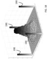
- a PCS 1024 QAM distribution is shown together with the QPSK pilot symbols.
- the PCS 1024 QAM allows a discrete and precise approximation of a Gaussian source signal.
- the QKD constellation is visible in the centre of the distribution and recognizable by its Gaussian form.
- the QPSK pilot symbols (190) are also clearly identified as 4 bars located at the extreme points of the distribution.
- 4 pilot symbols are used, each pilot signal corresponding to a point on a constellation diagram, the 4 points being equispaced around a circle. All the QPSK pilot symbols have therefore the same amplitude and have known phase values equally distributed.
- 4 pilot symbols are used having respective fixed phases values 45°, 135°, 225° and 315°.
- the apparatus (100A) further includes an optical attenuator (108) configured to adjust the power of the output symbols ( X k ) after interleaving.
- the signal power is adjusted so that the variance of the symbols after amplification is for example set to a given value V A (expressed in Shot Noise Units (SNU)).
- V A expressed in Shot Noise Units (SNU)
- the adjustment may come from QKD security proofs that prove that there exists an optimal V A such that the key rate is maximal.
- the optimal V A is given by security proofs and depends on the transmission parameters (e.g. T, x, where T is the transmittance of the channel, x is the variance of the excess noise, i.e. the increase in noise caused by Eve) and / or the length of the optical fiber (120).
- the amplified optical signal is transmitted to Bob (receiver side) through an unsecure quantum channel, here an optical channel being an optical fiber (120).
- the unsecure quantum channel attenuates the transmitted optical signal by the transmittance T and adds excess noise having a variance ç. Excess noise also comes from system and DSP (115) impairments.
- An authenticated classical channel (130) may be used in parallel as explained in introduction.
- the quantum shot noise is the noise induced by quantum uncertainty of the measurement. It may be modelled as a white additive Gaussian noise. By estimating the excess noise compared to the quantum shot noise, we obtain a bound on the increase of noise induced by Eve's measurement.
- the variance ç of the excess noise (in SNU, Shot Noise Unit) is an important parameter for measuring the system performance. The higher it is the shorter will be the length of the secure key that can be extracted from the random data left untouched by Eve. Therefore, it is a challenge to propose algorithms as optimal as possible.
- V A and values of the power of the QKD symbols, the excess noise, the power of the total noise in CVQKD system may be given in Shot Noise Unit (or SNU). If N o is the value of the shot noise power (in W for example), then the power of the QKD modulation is V A N o in W.
- the apparatus (100B) at receiver side includes a laser (111) and coherent receiver (112) for coherent detection of the successive symbols ( Y k ).
- the laser (111) is a local oscillator configured to beat with the received signal and to convert the received signal to a baseband signal. It is used for coherent detection.
- the coherent receiver is configured to decode the optical signal received through the fiber (120) and to extract an electrical signal representing the successive symbols ( Y k ).
- the coherent receiver may for example include an array of photodetectors for optical to electrical conversion. The decoded electrical signal may then be converted to a digital decoded signal by an analog to digital converter.
- the coherent receiver (112) includes photodiodes having a quantum efficiency ⁇ defined as the ratio of the average number of output electrons to the average number of input photons.
- the coherent receiver (112) adds noise, such that the variance of the total noise at receiver side is 1 + V el where 1 is the variance of the shot noise and V el is the variance of the thermal electrical noise from the receiver (100B).
- the symbols received and extracted at Bob's apparatus are noted ( Y k ).
- the apparatus (100B) also include a digital signal processing (DSP) circuitry (115) for determining the QKD symbols ( S k ) from the extracted symbols ( Y k ).
- DSP digital signal processing circuitry
- Fig. 2A shows a schematic representation of a CVQKD system including a digital signal processing (DSP) circuitry (115) for determining the QKD symbols ( S k ) from the extracted symbols ( Y k ).
- DSP digital signal processing
- S k the QKD symbols
- Y k the extracted symbols
- a polarization correction is applied to generate a first corrected symbol ⁇ k
- a carrier phase correction applied to the first corrected symbol ⁇ k to generate a second corrected symbol X ⁇ k representing an estimate of the symbol X k transmitted by Alice.
- the notation used in this schematic will be used in the following description.
- the polarization correction may be applied by a first circuitry (216) and the carrier phase correction by a second circuitry (217) as represented by FIG. 2A , or both corrections be performed by a same circuitry.
- Polarization Correction is to apply a correction to cancel the effects of changes of polarization state caused by birefringence of the optical fiber (120).
- a change of the polarization state may be caused for example by twists of the fiber (120).
- Polarization of light can be described using either 2D complex vectors in the Jones space or 3D real vectors in the Stokes space.
- the proposed algorithm makes use of the matching relationships between both formalisms. See for example the article by J. P. Gordon and H. Kogelnik, entitled ⁇ PMD fundamentals: Polarization mode dispersion in optical fibers', PNAS, vol. 97, no. 9, pp. 4541-4550, Apr. 2000, doi: 10.1073/pnas.97.9.4541 .
- Jones' formalism is a matrix formalism allowing to describe the polarization state of light wave, or in a general way, of an electromagnetic wave, and its evolution through an optical system.
- This vector s s x s y defines the polarization state of the electric field of the light wave at a given time.
- a change of the polarization state may be modelled in the Stokes formalism by a 3 ⁇ 3 real rotation matrix R isomorphic to U.
- U ⁇ 1 r ⁇ r + ⁇ 2 r ⁇ ⁇ r ⁇ where ⁇ 1 and ⁇ 2 are the eigenvalues of U and r ⁇ designates the conjugate transposed vector of r.
- U e ⁇ j ⁇ / 2 r ⁇ r + e j ⁇ / 2 r ⁇ ⁇ r ⁇ where the angle ⁇ is the rotation angle according to the article by J. P. Gordon and H. Kogelnik.
- the angle ⁇ k represents a variation of phase caused by the laser (101) at Alice's apparatus or more generally a phase noise on the phase of the source signal generated by the laser (101).
- the additive noise w k may include shot noise. It may also include additive noise from the electrical components.
- the additive noise w k is modelled here as an additive white Gaussian noise.
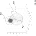
- the Stokes vector is on a Poincaré sphere (200) of radius equal to 1 defined by equation (EQP) in Stokes space.
- EQP equation
- the Stokes vector of a decoded symbol Y k can be computed using the equations (EQS).
- This computation method By this computation method, the noiseless polarization state independent from the phase noise of the single polarization optical field, the phase noise being not detectable in the Stokes space.
- This computation method is referred herein to as a Poincaré sphere-based polarization alignment algorithm. This computation method may be applied to all the symbols, whether QKD symbols or pilots symbols or be applied only to the pilot symbols.
- the rotation axis and the rotation angle ⁇ are estimated in Stokes space from the Stokes vector is and the regression vector .
- the linear regression to compute the estimate of the noiseless polarization state may be applied on a sliding window, e.g. on a given number K of Stokes vectors representing the K last decoded symbols Y k .
- the inverse Jones matrix may be computed periodically and over a sliding window.
- Carrier Phase Correction is to apply a correction to cancel the effects of the variation of phase noise caused by the linewidth of the laser beam.
- phase noise is determined for the pilot symbols and then the phase noise can be approximated for the QKD symbols.
- Alice and Bob share the knowledge concerning the pilots and their interleaving pattern, i.e. the phase of the pilots and the order in which the pilot are sent by Alice is known to Bob and may be shared between Alice and Bob (for example through the classical communication channel).
- the Carrier Phase Correction allows the determination of the phase noise.
- the Carrier Phase Correction is applied only to the corrected pilot symbols ⁇ k corresponding to a pilot.
- the Carrier Phase Correction may be based on an Extended Kalman Filter and on the QPSK pilots.
- the principle is to estimate the phase noise ⁇ k at time k for the symbol X k based on the observation ⁇ k when the symbol X k is a pilot P j .
- the index k will be used as the pilot index, bearing in mind that the Kalman filter is applied only to the pilot symbols.
- the receiver (100B) knows the order in which the pilots are sent. Therefore the symbol X k corresponding to the received symbol Y k is known to the receiver when X k is a pilot.
- w k is the additive noise, assumed to be a random variable having a Gaussian distribution whose mean is zero and variance ⁇ 2 is an experimental value that may be calibrated in various ways (e.g. the signal input of the coherent receiver may be shut down to estimate the additive noise variance) before the QKD transmission and can also be optimized during transmission.
- the additive noise ⁇ k on phase is assumed to be a random variable having a Gaussian distribution whose mean is zero and variance ⁇ 2 .
- the additive noise ⁇ k is induced by both the source laser (101) and the laser (111) at receiver side.
- the phase noise ⁇ k is here modelled here as a Wiener process along a straight line.
- the purpose is to obtain an estimate of the phase noise ⁇ k of the carrier phase on the pilots.
- a predicted state estimate is defined as ⁇ ⁇ k
- k ⁇ 1 ⁇ ⁇ k ⁇ 1
- a predicted variance estimate is defined as P k
- k ⁇ 1 P k ⁇ 1 + ⁇ 2
- k -1 may be arbitrary defined (e.g. equal to 0).
- the algorithm may be applied firstly during a convergence phase to achieve convergence of the values. Then, when we compute the excess noise, we can get rid of the values used for the first symbols.
- the value ⁇ 0 is the initial value of ⁇ k
- k -1 for k 0 and may also be arbitrary.
- k ⁇ 1 + ⁇ 2 K k P k
- k ⁇ 1 H k ⁇ S k ⁇ 1 ⁇ ⁇ k ⁇ ⁇ k
- k ⁇ 1 + K k y ⁇ k P k P k
- a moving average or low pass filter may be applied to the values of the estimated phase noise ⁇ k .
- the window size for this moving average may for example be of 2 to 4 values of the estimated phase noise ⁇ k .
- the size of this window may be adjusted such that more than two pilot symbols are used for estimating the phase noise for a QKD symbol.
- the determination of the rotation matrix R representing the polarization impairment as described by reference to FIGS. 2A and 2B may be performed on the basis of input symbols including pilot symbols and QKD symbols or alternatively on the basis only to the input symbols Y k corresponding to pilot symbols (but not to the QKD symbols).
- FIG. 2C shows a schematic view of an apparatus (220) for processing input symbols at receiver side.
- the input symbols include QPSK pilot symbols temporally multiplexed with QKD symbols representing random bits of at least one random key.
- the quadratures values of QKD symbols follow a modulation map, corresponding to a QAM-based PCS modulation map.
- the apparatus includes means (226, 227) for processing the pilot symbols and means (236, 237) for processing the QKD symbols.
- the means (226, 227) for processing the pilot symbols may include a circuitry (226) configured to perform polarization estimation only on the pilot symbols (but not to the QKD symbols).
- This polarization estimation circuitry (226) may be based on the determination of a rotation matrix R in the Stokes space representing the polarization impairment and the determination of the inverse matrix ⁇ -1 as described by reference to FIGS. 2A and 2B .
- the determination of the rotation matrix may include:
- the determination of the inverse matrix may include:
- the means (226, 227) for processing the pilot symbols may include another circuitry (227) for performing phase noise estimation on the pilot symbols.
- This phase noise estimation circuitry (227) may be based on the Kalman filter as described by reference to FIGS. 2A and is configured to generate estimated phase noise values ⁇ k for the pilot symbols.
- Applying a phase correction to a first corrected QKD symbols ⁇ k may include estimating a phase noise value for the corresponding QKD symbol by applying a linear interpolation to phase noise values estimated for at least a first pilot symbol and at least one second pilot symbol between which the QKD symbol is temporally interleaved and applying the estimated phase noise value obtained for a QKD symbol to perform a phase correction on a first QKD corrected symbols ⁇ k corresponding to the concerned QKD symbol.
- FIG. 3 shows a flowchart of a method for monitoring smart devices according to one or more example embodiments. The steps of the method may be implemented by an apparatus for random key decoding according to any example described herein.
- the input symbols include Quadrature Phase Shift Keying, QPSK, pilot symbols temporally multiplexed with QKD symbols representing random bits to be used for random key transmission and quantum key generation.
- the quadratures values of the QKD symbols follow a modulation map that is a QAM-based PCS modulation map defining a mapping function for the random bits.
- a polarization correction is applied to the input symbols to generate respectively first corrected QKD symbols and corrected pilot symbols.
- the polarization correction is based at least on the pilot symbols.
- the polarization correction may be determined based on the pilot symbols only or based on the input pilot symbols and the input QKD symbol.
- a carrier phase correction is applied to the first QKD corrected symbols to generate second corrected QKD symbols representing an estimate of the at least one random key.
- the carrier phase correction is determined based on the corrected pilot symbols obtained at step 310.
- Applying the polarization correction may include determining a rotation matrix in a Stokes space representing a polarization impairment based at least on the pilot symbols, determining an inverse matrix of the Jones matrix associated to the rotation matrix and applying in a Jones space the inverse matrix to vectors representing the QKD symbols.
- Determining the rotation matrix may include:
- Determining the inverse matrix may include:
- Applying the carrier phase correction may include applying a Kalman filter to the corrected pilot symbols obtained from corresponding pilot symbols to estimate corresponding phase noise values for the corresponding pilot symbols and estimating a phase noise value of a QKD symbol by applying a linear interpolation to phase noise values estimated for at least a first pilot symbol and at least one second pilot symbol between which the QKD symbol is temporally interleaved.
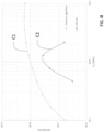
- Fig. 4 show a comparison of Poincaré sphere-based polarization demultiplexing algorithm described herein (curve C1) and DD-LMS (Direct Detection Least Mean Square) algorithm (curve C2) in term of SKR (Secret or Secure Key Rate) as a function of the modulation variance V A used at Alice's apparatus and using a 25 km optical fiber.
- the DD-LMS is for example described by K. Kikuchi, 'Fundamentals of Coherent Optical Fiber Communications', J. Lightwave Technol., JLT, vol. 34, no. 1, pp. 157-179, Jan. 2016 .
- the DD-LMS uses coherent transmission and detection.
- the method described herein clearly outperforms the DD-LMS algorithm and allows to achieve higher SKR. Moreover, it exhibits key rates of 100 Mbps and higher.
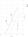
- Fig. 5 shows a comparison between the Kalman-based Carrier Phase Estimation algorithm (curve C3) disclosed herein and a more simple algorithm (curve C4) using a moving average applied to the measured phase noise on the pilots (without applying a Kalman filter to the phase of the pilot) and then a linear interpolation for the QKD symbols.
- the comparison is performed in term of excess noise SKR and modulation variance V A .
- the use of Kalman filter enables the extraction of SKR for V A values lower than 6 SNU while no key can be extracted with the simple algorithm without Kalman filter.
- Fig. 6 shows a comparison between the performance of a QPSK modulation (curve C6) in replacement of a PCS 1024 QAM as described herein and PCS 1024 QAM modulation (curve C5) in terms of SKR and link distance (optical fiber length) for optimal parameters.
- QPSK we used the QPSK security proof (see document by Anthony Leverrier, Philippe Grangier, entitled “Continuous-variable quantum-key-distribution protocols with a non-Gaussian modulation", Physical Review A, American Physical Society, 2011, 83 (4), pp.042312.10.1103 ).
- PCS 1024 QAM we used the gaussian security proof as disclosed by F.
- any functions, engines, block diagrams, flow diagrams, state transition diagrams and / or flowcharts herein represent conceptual views of illustrative circuitry embodying the principles of the invention.
- any flow charts, flow diagrams, state transition diagrams, pseudo code, and the like represent various processes which may be substantially represented in computer readable medium and so executed by a computer or processing apparatus, whether or not such computer or processor is explicitly shown.
- a process may be terminated when its operations are completed, but may also have additional steps not included in the figure.
- a process may correspond to a method, function, procedure, subroutine, subprogram, etc. When a process corresponds to a function, its termination may correspond to a return of the function to the calling function or the main function.
- Each described computation function, block, step can be implemented in hardware, software, firmware, middleware, microcode, or any suitable combination thereof. If implemented in software, the computation functions, blocks of the block diagrams and/or flowchart illustrations can be implemented by computer program instructions / software code, which may be stored or transmitted over a computer-readable medium, or loaded onto a general purpose computer, special purpose computer or other programmable processing apparatus and / or system to produce a machine, such that the computer program instructions or software code which execute on the computer or other programmable processing apparatus, create the means for implementing the functions described herein.
- the program code or code segments to perform the necessary tasks may be stored in a machine or computer readable medium such as a computer readable storage medium.
- a processor or processors will perform the necessary tasks.
- at least one memory may include or store computer program code
- the at least one memory and the computer program code may be configured to, with at least one processor, cause an apparatus to perform the necessary tasks.
- the processor, memory and example algorithms, encoded as computer program code serve as means for providing or causing performance of operations discussed herein.
- block denoted as "means configured to perform " (a certain function) shall be understood as functional blocks comprising circuitry that is adapted for performing or configured to perform a certain function.
- a means being configured to perform a certain function does, hence, not imply that such means necessarily is performing said function (at a given time instant).
- any entity described herein as “means” may correspond to or be implemented as “one or more modules", “one or more devices”, “one or more units”, etc.
- the functions may be provided by a single dedicated processor, by a single shared processor, or by a plurality of individual processors, some of which may be shared.
- processor or “controller” should not be construed to refer exclusively to hardware capable of executing software, and may implicitly include, without limitation, digital signal processor (DSP) hardware, network processor, application specific integrated circuit (ASIC), field programmable gate array (FPGA), read only memory (ROM) for storing software, random access memory (RAM), and non-volatile storage.
- DSP digital signal processor
- ASIC application specific integrated circuit
- FPGA field programmable gate array
- ROM read only memory
- RAM random access memory
- non-volatile storage non-volatile storage.
- Other hardware conventional or custom, may also be included. Their function may be carried out through the operation of program logic, through dedicated logic, through the interaction of program control and dedicated logic, or even manually, the particular technique being selectable by the implementer as more specifically understood from the context.
- circuit may refer to one or more or all of the following:
- circuitry also covers an implementation of merely a hardware circuit or processor (or multiple processors) or portion of a hardware circuit or processor and its (or their) accompanying software and/or firmware.
- circuitry also covers, for example and if applicable to the particular claim element, an integrated circuit for a network element or network node or any other computing device or network device.
- circuitry may cover digital signal processor (DSP) hardware, network processor, application specific integrated circuit (ASIC), field programmable gate array (FPGA), etc.
- DSP digital signal processor
- ASIC application specific integrated circuit
- FPGA field programmable gate array
- circuit may be or include, for example, hardware, programmable logic, a programmable processor that executes software or firmware, and/or any combination thereof (e.g. a processor, control unit/entity, controller) to execute instructions or software and control transmission and receptions of signals, and a memory to store data and/or instructions.
- a processor control unit/entity, controller
- the “circuit” or “circuitry” may also make decisions or determinations, generate frames, packets or messages for transmission, decode received frames or messages for further processing, and other tasks or functions described herein.
- the circuitry may control transmission of signals or messages over a radio network, and may control the reception of signals or messages, etc., via a radio network (e.g., after being down-converted by radio transceiver, for example).
- the term “storage medium,” “computer readable storage medium” or “non-transitory computer readable storage medium” may represent one or more devices for storing data, including read only memory (ROM), random access memory (RAM), magnetic RAM, core memory, magnetic disk storage mediums, optical storage mediums, flash memory devices and/or other tangible machine-readable mediums for storing information.
- ROM read only memory
- RAM random access memory
- magnetic RAM magnetic RAM
- core memory magnetic disk storage mediums
- optical storage mediums optical storage mediums
- flash memory devices and/or other tangible machine-readable mediums for storing information.
- computer-readable medium may include, but is not limited to, portable or fixed storage devices, optical storage devices, and various other mediums capable of storing, containing or carrying instruction(s) and/or data.
- first, second, etc. may be used herein to describe various elements, these elements should not be limited by these terms. These terms are only used to distinguish one element from another. For example, a first element could be termed a second element, and similarly, a second element could be termed a first element, without departing from the scope of this disclosure.
- the term "and/or,” includes any and all combinations of one or more of the associated listed items.
Landscapes
- Engineering & Computer Science (AREA)
- Physics & Mathematics (AREA)
- Theoretical Computer Science (AREA)
- General Physics & Mathematics (AREA)
- Mathematical Physics (AREA)
- Computer Security & Cryptography (AREA)
- Computer Networks & Wireless Communication (AREA)
- Signal Processing (AREA)
- Mathematical Optimization (AREA)
- Mathematical Analysis (AREA)
- Computational Mathematics (AREA)
- Pure & Applied Mathematics (AREA)
- Data Mining & Analysis (AREA)
- Electromagnetism (AREA)
- Algebra (AREA)
- Databases & Information Systems (AREA)
- Software Systems (AREA)
- General Engineering & Computer Science (AREA)
- Computing Systems (AREA)
- Optical Communication System (AREA)
Claims (14)
- Appareil (100A) pour une transmission de clés aléatoires, l'appareil comprenant- un laser (101) configuré pour générer un signal optique de source cohérente ;- un générateur quantique de nombres aléatoires, QRNG, (105) configuré pour générer des bits aléatoires (Ri ) d'au moins une clé aléatoire ;- un modulateur électro-optique (107) configuré pour moduler le signal optique de source cohérente pour générer un signal optique modulé comportant des symboles pilotes de modulation par déplacement de phase en quadrature, QPSK, multiplexés temporellement avec des symboles de distribution quantique de clés, QKD, représentant les bits aléatoires,dans lequel des valeurs de quadrature des symboles QKD suivent une carte de modulation, dans lequel la carte de modulation est une carte de modulation de mise en forme probabiliste de constellation, PCS, basée sur une modulation d'amplitude en quadrature, QAM, définissant une fonction de mappage pour les bits aléatoires.
- Appareil selon la revendication 1, comprenant en outre un atténuateur de puissance configuré pour ajuster la variance de la puissance du signal optique modulé.
- Appareil (100B) de décodage de clé aléatoire, l'appareil comprenant des moyens pourobtenir des symboles d'entrée, dans lequel les symboles d'entrée comportent des symboles pilotes de modulation par déplacement de phase en quadrature, QPSK, multiplexés temporellement avec des symboles de distribution quantique de clés, QKD, représentant des bits aléatoires d'au moins une clé aléatoire, dans lequel des valeurs de quadrature des symboles QKD suivent une carte de modulation, dans lequel la carte de modulation est une carte de modulation de mise en forme probabiliste de constellation, PCS, basée sur une modulation d'amplitude en quadrature, QAM, définissant une fonction de mappage pour les bits aléatoires ;appliquer une correction de polarisation aux symboles d'entrée pour générer des premiers symboles QKD corrigés et des symboles pilotes corrigés, dans lequel la correction de polarisation est déterminée au moins sur la base des symboles pilotes ;appliquer une correction de phase de porteuse aux premiers symboles QKD corrigés pour générer des deuxième symboles QKD corrigés représentant une estimation de ladite au moins une clé aléatoire, dans lequel la correction de phase de porteuse est déterminée sur la base des symboles pilotes corrigés.
- Appareil selon la revendication 3, dans lequel l'application de la correction de polarisation comporte la détermination d'une matrice de rotation dans un espace de Stokes représentant une altération de la polarisation, la détermination d'une matrice inverse d'une matrice de Jones associée à la matrice de rotation, et l'application de la matrice inverse dans un espace de Jones à des vecteurs représentant les symboles d'entrée.
- Appareil selon la revendication 4, dans lequel la détermination de la matrice de rotation comporte- la conversion de symboles d'entrée en vecteurs correspondants dans l'espace de Stokes ;- la réalisation d'une régression linéaire sur les vecteurs pour obtenir un vecteur de régression (š) ;- la détermination de la matrice de rotation dans l'espace de Stokes à partir du vecteur de régression (š).
- Appareil selon la revendication 4 ou 5, dans lequel la détermination de la matrice inverse comporte- la conversion de la matrice de rotation dans l'espace de Stokes en une matrice de Jones dans l'espace de Jones ;- l'inversion de la matrice de Jones dans l'espace de Jones pour obtenir la matrice inverse.
- Appareil selon l'une des revendications 3 à 6, dans lequel l'application de la correction de phase de porteuse comprend l'application d'un filtre de Kalman aux symboles pilotes obtenus corrigés à partir de symboles pilotes correspondants pour estimer des valeurs de bruit de phase pour les symboles pilotes correspondants, et estimer une valeur de bruit de phase pour un symbole QKD en appliquant une interpolation linéaire aux valeurs de bruit de phase estimées pour au moins un premier symbole pilote et au moins un deuxième symbole pilote entre lesquels le symbole QKD est entrelacé temporellement.
- Appareil (100B) selon l'une des revendications 3 à 7, comprenant en outre un laser (111) couplé à un circuit récepteur cohérent pour la réception et l'extraction des symboles d'un signal optique modulé.
- Procédé de décodage de clé aléatoire, le procédé comprenantl'obtention (300) de symboles d'entrée, dans lequel les symboles d'entrée comportent des symboles pilotes de modulation par déplacement de phase en quadrature, QPSK, multiplexés temporellement avec des symboles de distribution quantique de clés, QKD, représentant des bits aléatoires d'au moins une clé aléatoire, dans lequel des valeurs de quadrature des symboles QKD suivent une carte de modulation, dans lequel la carte de modulation est une carte de modulation de mise en forme probabiliste de constellation, PCS, basée sur une modulation d'amplitude en quadrature, QAM, définissant une fonction de mappage pour les bits aléatoires ;l'application (310) d'une correction de polarisation aux symboles d'entrée pour générer des premiers symboles QKD corrigés et des symboles pilotes corrigés, dans lequel la correction de polarisation est déterminée au moins sur la base des symboles pilotes ;l'application (320) d'une correction de phase de porteuse aux premiers symboles QKD corrigés pour générer des deuxième symboles QKD corrigés représentant une estimation de ladite clé aléatoire, dans lequel la correction de phase de porteuse est déterminée sur la base des symboles pilotes corrigés.
- Procédé selon la revendication 9, dans lequel l'application de la correction de polarisation comporte la détermination d'une matrice de rotation dans un espace de Stokes représentant une altération de la polarisation au moins sur la base des symboles pilotes, la détermination d'une matrice inverse d'une matrice de Jones associée à la matrice de rotation, et l'application de la matrice inverse dans un espace de Jones à des vecteurs représentant les symboles QKD.
- Procédé selon la revendication 10, dans lequel la détermination de la matrice de rotation comporte- la conversion de symboles d'entrée en vecteurs correspondants dans l'espace de Stokes ;- la réalisation d'une régression linéaire sur les vecteurs pour obtenir un vecteur de régression (š) ;- la détermination d'une matrice de rotation dans l'espace de Stokes à partir du vecteur de régression (š).
- Procédé selon la revendication 10 ou 11, dans lequel la détermination de la matrice inverse comporte- la conversion de la matrice de rotation en une matrice de Jones dans l'espace de Jones ;- l'inversion de la matrice de Jones dans l'espace de Jones pour obtenir la matrice inverse.
- Procédé selon l'une des revendications 9 à 12, dans lequel l'application de la correction de phase de porteuse comprend l'application d'un filtre de Kalman aux symboles pilotes obtenus corrigés à partir de symboles pilotes correspondants pour estimer des valeurs de bruit de phase respective pour les symboles pilotes correspondants, et estimer une valeur de bruit de phase pour un symbole QKD en appliquant une interpolation linéaire aux valeurs de bruit de phase estimées pour au moins un premier symbole pilote et au moins un deuxième symbole pilote entre lesquels le symbole QKD est entrelacé temporellement.
- Support non transitoire lisible par ordinateur stockant des instructions exécutables par ordinateur qui, lorsqu'elles sont exécutées par au moins un processeur sur un appareil, amènent l'appareil à réaliser un procédé de décodage de clé aléatoire selon l'une des revendications 9 à 13.
Priority Applications (2)
| Application Number | Priority Date | Filing Date | Title |
|---|---|---|---|
| EP20306420.9A EP4002749B1 (fr) | 2020-11-20 | 2020-11-20 | Distribution de clé quantique variable en continu |
| US17/529,451 US12335377B2 (en) | 2020-11-20 | 2021-11-18 | Continuous variable quantum key distribution |
Applications Claiming Priority (1)
| Application Number | Priority Date | Filing Date | Title |
|---|---|---|---|
| EP20306420.9A EP4002749B1 (fr) | 2020-11-20 | 2020-11-20 | Distribution de clé quantique variable en continu |
Publications (2)
| Publication Number | Publication Date |
|---|---|
| EP4002749A1 EP4002749A1 (fr) | 2022-05-25 |
| EP4002749B1 true EP4002749B1 (fr) | 2024-10-16 |
Family
ID=74586700
Family Applications (1)
| Application Number | Title | Priority Date | Filing Date |
|---|---|---|---|
| EP20306420.9A Active EP4002749B1 (fr) | 2020-11-20 | 2020-11-20 | Distribution de clé quantique variable en continu |
Country Status (2)
| Country | Link |
|---|---|
| US (1) | US12335377B2 (fr) |
| EP (1) | EP4002749B1 (fr) |
Families Citing this family (6)
| Publication number | Priority date | Publication date | Assignee | Title |
|---|---|---|---|---|
| US12200114B1 (en) * | 2021-10-21 | 2025-01-14 | Wells Fargo Bank, N.A. | Systems and methods for mobile quantum key distribution |
| CN116112093B (zh) * | 2022-12-28 | 2024-07-23 | 中国电子科技集团公司第三十研究所 | Cv-qkd芯片系统的高精度调制方差控制方法与装置 |
| CN115952551B (zh) * | 2023-03-15 | 2023-05-16 | 山东知方源科技信息有限公司 | 一种用于建筑bim模型的数据处理方法 |
| CN116388971B (zh) * | 2023-03-24 | 2025-07-01 | 华中科技大学 | 一种安全密钥分发装置、方法和存储介质 |
| CN119728088B (zh) * | 2023-09-28 | 2025-09-09 | 中国移动通信有限公司研究院 | 数据加密方法、装置、设备及可读存储介质 |
| CN119966621B (zh) * | 2025-01-27 | 2025-11-21 | 东华大学 | 基于Polar码和有损压缩的连续变量量子密钥分发多维协商方法 |
Family Cites Families (8)
| Publication number | Priority date | Publication date | Assignee | Title |
|---|---|---|---|---|
| EP2651051A1 (fr) * | 2012-04-13 | 2013-10-16 | Alcatel Lucent | Algorithme d'atténuation de polarisation croisée non linéaire |
| AU2013265020B2 (en) | 2012-05-23 | 2017-10-12 | University Of Leeds | Secure communication |
| WO2016099565A1 (fr) | 2014-12-19 | 2016-06-23 | Nokia Technologies Oy | Puce photonique pour distribution quantique de clés à variation continue |
| US9641279B2 (en) * | 2015-01-14 | 2017-05-02 | Alcatel-Lucent Usa Inc. | Stokes-vector-based transmission and detection of optical polarization-division-multiplexed signals |
| KR101714315B1 (ko) * | 2016-05-04 | 2017-03-08 | 현대자동차주식회사 | 보간법을 이용한 터치 입력 인식 장치 및 방법 |
| CN109510701B (zh) | 2017-09-15 | 2021-10-01 | 华为技术有限公司 | 连续变量量子密钥分发设备及方法 |
| GB201720063D0 (en) * | 2017-12-01 | 2018-01-17 | Cambridge Entpr Ltd | Quantum security systems |
| WO2021079647A1 (fr) * | 2019-10-21 | 2021-04-29 | 日本電気株式会社 | Dispositif de sortie de quantité de mise à jour de coefficient, dispositif de mise à jour de coefficient, procédé de sortie de quantité de mise à jour de coefficient, et support d'enregistrement |
-
2020
- 2020-11-20 EP EP20306420.9A patent/EP4002749B1/fr active Active
-
2021
- 2021-11-18 US US17/529,451 patent/US12335377B2/en active Active
Also Published As
| Publication number | Publication date |
|---|---|
| US20220166612A1 (en) | 2022-05-26 |
| US12335377B2 (en) | 2025-06-17 |
| EP4002749A1 (fr) | 2022-05-25 |
Similar Documents
| Publication | Publication Date | Title |
|---|---|---|
| EP4002749B1 (fr) | Distribution de clé quantique variable en continu | |
| Pan et al. | The evolution of quantum secure direct communication: On the road to the qinternet | |
| CA2973284C (fr) | Communication a securite durable a partir de communication quantique chiffree securisee a court terme | |
| Trinh et al. | Quantum key distribution over FSO: Current development and future perspectives | |
| US8433070B2 (en) | Systems and methods for stabilization of interferometers for quantum key distribution | |
| KR101833956B1 (ko) | 연속 변수 양자 암호 키분배 위상 보정 시스템 | |
| EP3678306B1 (fr) | Appareil et procédé de génération de clé | |
| EP4107902A1 (fr) | Procédé de distribution quantique de clé, procédé d'émission d'un signal optique, procédé de réception d'un signal optique et récepteur d'un signal optique pour distribution quantique de clé | |
| Sun et al. | Design and implementation of a practical quantum secure direct communication system | |
| Chin et al. | Digital synchronization for continuous-variable quantum key distribution | |
| EP4037248A1 (fr) | Réduction de bruit excessif pour la distribution de clé quantique variable continue | |
| KR102709494B1 (ko) | 통신 시스템에서 양자 키 분배를 위한 패러데이 회전 거울의 편광 왜곡을 보정하기 위한 방법 및 장치 | |
| Notarnicola et al. | Probabilistic amplitude shaping for continuous-variable quantum key distribution with discrete modulation over a wiretap channel | |
| US12074970B2 (en) | Quantum key distribution method, device, and system | |
| Hosseinidehaj et al. | CV-QKD with Gaussian and non-Gaussian entangled states over satellite-based channels | |
| CN101176298B (zh) | 在多信道量子通信系统内的相位锁定 | |
| Sisodia et al. | FSO-QKD protocols under free-space losses and device imperfections: a comparative study: M. Sisodia et al. | |
| Hosseinidehaj et al. | CV-MDI quantum key distribution via satellite | |
| Kuang et al. | Quantum public key distribution using randomized Glauber states | |
| Jain et al. | qTReX: A semi-autonomous continuous-variable quantum key distribution system | |
| WO2023120563A1 (fr) | Système de partage de clé cryptographique | |
| Xiao et al. | Analysis of polarization coding for subcarrier multiplexing quantum key distribution: H. Xiao et al. | |
| Rios | Experimental Characterization of a Discrete Gaussian-Modulated Quantum Key Distribution System | |
| Chen et al. | Low Encryption Penalty LEO-to-Earth Secure Laser Communication Based on Quantum Noise Stream Cipher | |
| Chin et al. | Phase compensation for continuous variable quantum key distribution |
Legal Events
| Date | Code | Title | Description |
|---|---|---|---|
| PUAI | Public reference made under article 153(3) epc to a published international application that has entered the european phase |
Free format text: ORIGINAL CODE: 0009012 |
|
| STAA | Information on the status of an ep patent application or granted ep patent |
Free format text: STATUS: THE APPLICATION HAS BEEN PUBLISHED |
|
| AK | Designated contracting states |
Kind code of ref document: A1 Designated state(s): AL AT BE BG CH CY CZ DE DK EE ES FI FR GB GR HR HU IE IS IT LI LT LU LV MC MK MT NL NO PL PT RO RS SE SI SK SM TR |
|
| STAA | Information on the status of an ep patent application or granted ep patent |
Free format text: STATUS: REQUEST FOR EXAMINATION WAS MADE |
|
| 17P | Request for examination filed |
Effective date: 20221123 |
|
| RBV | Designated contracting states (corrected) |
Designated state(s): AL AT BE BG CH CY CZ DE DK EE ES FI FR GB GR HR HU IE IS IT LI LT LU LV MC MK MT NL NO PL PT RO RS SE SI SK SM TR |
|
| GRAP | Despatch of communication of intention to grant a patent |
Free format text: ORIGINAL CODE: EPIDOSNIGR1 |
|
| STAA | Information on the status of an ep patent application or granted ep patent |
Free format text: STATUS: GRANT OF PATENT IS INTENDED |
|
| INTG | Intention to grant announced |
Effective date: 20240514 |
|
| GRAS | Grant fee paid |
Free format text: ORIGINAL CODE: EPIDOSNIGR3 |
|
| GRAA | (expected) grant |
Free format text: ORIGINAL CODE: 0009210 |
|
| STAA | Information on the status of an ep patent application or granted ep patent |
Free format text: STATUS: THE PATENT HAS BEEN GRANTED |
|
| AK | Designated contracting states |
Kind code of ref document: B1 Designated state(s): AL AT BE BG CH CY CZ DE DK EE ES FI FR GB GR HR HU IE IS IT LI LT LU LV MC MK MT NL NO PL PT RO RS SE SI SK SM TR |
|
| REG | Reference to a national code |
Ref country code: GB Ref legal event code: FG4D |
|
| REG | Reference to a national code |
Ref country code: CH Ref legal event code: EP Ref country code: DE Ref legal event code: R096 Ref document number: 602020039495 Country of ref document: DE |
|
| REG | Reference to a national code |
Ref country code: IE Ref legal event code: FG4D |
|
| REG | Reference to a national code |
Ref country code: LT Ref legal event code: MG9D |
|
| REG | Reference to a national code |
Ref country code: NL Ref legal event code: MP Effective date: 20241016 |
|
| REG | Reference to a national code |
Ref country code: AT Ref legal event code: MK05 Ref document number: 1733813 Country of ref document: AT Kind code of ref document: T Effective date: 20241016 |
|
| PG25 | Lapsed in a contracting state [announced via postgrant information from national office to epo] |
Ref country code: NL Free format text: LAPSE BECAUSE OF FAILURE TO SUBMIT A TRANSLATION OF THE DESCRIPTION OR TO PAY THE FEE WITHIN THE PRESCRIBED TIME-LIMIT Effective date: 20241016 |
|
| PG25 | Lapsed in a contracting state [announced via postgrant information from national office to epo] |
Ref country code: NL Free format text: LAPSE BECAUSE OF FAILURE TO SUBMIT A TRANSLATION OF THE DESCRIPTION OR TO PAY THE FEE WITHIN THE PRESCRIBED TIME-LIMIT Effective date: 20241016 |
|
| PG25 | Lapsed in a contracting state [announced via postgrant information from national office to epo] |
Ref country code: PT Free format text: LAPSE BECAUSE OF FAILURE TO SUBMIT A TRANSLATION OF THE DESCRIPTION OR TO PAY THE FEE WITHIN THE PRESCRIBED TIME-LIMIT Effective date: 20250217 Ref country code: HR Free format text: LAPSE BECAUSE OF FAILURE TO SUBMIT A TRANSLATION OF THE DESCRIPTION OR TO PAY THE FEE WITHIN THE PRESCRIBED TIME-LIMIT Effective date: 20241016 Ref country code: IS Free format text: LAPSE BECAUSE OF FAILURE TO SUBMIT A TRANSLATION OF THE DESCRIPTION OR TO PAY THE FEE WITHIN THE PRESCRIBED TIME-LIMIT Effective date: 20250216 |
|
| PG25 | Lapsed in a contracting state [announced via postgrant information from national office to epo] |
Ref country code: FI Free format text: LAPSE BECAUSE OF FAILURE TO SUBMIT A TRANSLATION OF THE DESCRIPTION OR TO PAY THE FEE WITHIN THE PRESCRIBED TIME-LIMIT Effective date: 20241016 |
|
| PG25 | Lapsed in a contracting state [announced via postgrant information from national office to epo] |
Ref country code: BG Free format text: LAPSE BECAUSE OF FAILURE TO SUBMIT A TRANSLATION OF THE DESCRIPTION OR TO PAY THE FEE WITHIN THE PRESCRIBED TIME-LIMIT Effective date: 20241016 |
|
| PG25 | Lapsed in a contracting state [announced via postgrant information from national office to epo] |
Ref country code: ES Free format text: LAPSE BECAUSE OF FAILURE TO SUBMIT A TRANSLATION OF THE DESCRIPTION OR TO PAY THE FEE WITHIN THE PRESCRIBED TIME-LIMIT Effective date: 20241016 |
|
| PG25 | Lapsed in a contracting state [announced via postgrant information from national office to epo] |
Ref country code: NO Free format text: LAPSE BECAUSE OF FAILURE TO SUBMIT A TRANSLATION OF THE DESCRIPTION OR TO PAY THE FEE WITHIN THE PRESCRIBED TIME-LIMIT Effective date: 20250116 |
|
| PG25 | Lapsed in a contracting state [announced via postgrant information from national office to epo] |
Ref country code: LV Free format text: LAPSE BECAUSE OF FAILURE TO SUBMIT A TRANSLATION OF THE DESCRIPTION OR TO PAY THE FEE WITHIN THE PRESCRIBED TIME-LIMIT Effective date: 20241016 Ref country code: GR Free format text: LAPSE BECAUSE OF FAILURE TO SUBMIT A TRANSLATION OF THE DESCRIPTION OR TO PAY THE FEE WITHIN THE PRESCRIBED TIME-LIMIT Effective date: 20250117 Ref country code: AT Free format text: LAPSE BECAUSE OF FAILURE TO SUBMIT A TRANSLATION OF THE DESCRIPTION OR TO PAY THE FEE WITHIN THE PRESCRIBED TIME-LIMIT Effective date: 20241016 |
|
| PG25 | Lapsed in a contracting state [announced via postgrant information from national office to epo] |
Ref country code: PL Free format text: LAPSE BECAUSE OF FAILURE TO SUBMIT A TRANSLATION OF THE DESCRIPTION OR TO PAY THE FEE WITHIN THE PRESCRIBED TIME-LIMIT Effective date: 20241016 |
|
| PG25 | Lapsed in a contracting state [announced via postgrant information from national office to epo] |
Ref country code: RS Free format text: LAPSE BECAUSE OF FAILURE TO SUBMIT A TRANSLATION OF THE DESCRIPTION OR TO PAY THE FEE WITHIN THE PRESCRIBED TIME-LIMIT Effective date: 20250116 |
|
| REG | Reference to a national code |
Ref country code: CH Ref legal event code: PL |
|
| PG25 | Lapsed in a contracting state [announced via postgrant information from national office to epo] |
Ref country code: SM Free format text: LAPSE BECAUSE OF FAILURE TO SUBMIT A TRANSLATION OF THE DESCRIPTION OR TO PAY THE FEE WITHIN THE PRESCRIBED TIME-LIMIT Effective date: 20241016 |
|
| PG25 | Lapsed in a contracting state [announced via postgrant information from national office to epo] |
Ref country code: MC Free format text: LAPSE BECAUSE OF FAILURE TO SUBMIT A TRANSLATION OF THE DESCRIPTION OR TO PAY THE FEE WITHIN THE PRESCRIBED TIME-LIMIT Effective date: 20241016 |
|
| PG25 | Lapsed in a contracting state [announced via postgrant information from national office to epo] |
Ref country code: DK Free format text: LAPSE BECAUSE OF FAILURE TO SUBMIT A TRANSLATION OF THE DESCRIPTION OR TO PAY THE FEE WITHIN THE PRESCRIBED TIME-LIMIT Effective date: 20241016 |
|
| PG25 | Lapsed in a contracting state [announced via postgrant information from national office to epo] |
Ref country code: LU Free format text: LAPSE BECAUSE OF NON-PAYMENT OF DUE FEES Effective date: 20241120 |
|
| REG | Reference to a national code |
Ref country code: CH Ref legal event code: PL |
|
| REG | Reference to a national code |
Ref country code: DE Ref legal event code: R097 Ref document number: 602020039495 Country of ref document: DE |
|
| PG25 | Lapsed in a contracting state [announced via postgrant information from national office to epo] |
Ref country code: EE Free format text: LAPSE BECAUSE OF FAILURE TO SUBMIT A TRANSLATION OF THE DESCRIPTION OR TO PAY THE FEE WITHIN THE PRESCRIBED TIME-LIMIT Effective date: 20241016 |
|
| PG25 | Lapsed in a contracting state [announced via postgrant information from national office to epo] |
Ref country code: CH Free format text: LAPSE BECAUSE OF NON-PAYMENT OF DUE FEES Effective date: 20241130 |
|
| PG25 | Lapsed in a contracting state [announced via postgrant information from national office to epo] |
Ref country code: RO Free format text: LAPSE BECAUSE OF FAILURE TO SUBMIT A TRANSLATION OF THE DESCRIPTION OR TO PAY THE FEE WITHIN THE PRESCRIBED TIME-LIMIT Effective date: 20241016 |
|
| PG25 | Lapsed in a contracting state [announced via postgrant information from national office to epo] |
Ref country code: SK Free format text: LAPSE BECAUSE OF FAILURE TO SUBMIT A TRANSLATION OF THE DESCRIPTION OR TO PAY THE FEE WITHIN THE PRESCRIBED TIME-LIMIT Effective date: 20241016 |
|
| PG25 | Lapsed in a contracting state [announced via postgrant information from national office to epo] |
Ref country code: CZ Free format text: LAPSE BECAUSE OF FAILURE TO SUBMIT A TRANSLATION OF THE DESCRIPTION OR TO PAY THE FEE WITHIN THE PRESCRIBED TIME-LIMIT Effective date: 20241016 |
|
| PG25 | Lapsed in a contracting state [announced via postgrant information from national office to epo] |
Ref country code: IT Free format text: LAPSE BECAUSE OF FAILURE TO SUBMIT A TRANSLATION OF THE DESCRIPTION OR TO PAY THE FEE WITHIN THE PRESCRIBED TIME-LIMIT Effective date: 20241016 |
|
| PLBE | No opposition filed within time limit |
Free format text: ORIGINAL CODE: 0009261 |
|
| STAA | Information on the status of an ep patent application or granted ep patent |
Free format text: STATUS: NO OPPOSITION FILED WITHIN TIME LIMIT |
|
| REG | Reference to a national code |
Ref country code: BE Ref legal event code: MM Effective date: 20241130 |
|
| PG25 | Lapsed in a contracting state [announced via postgrant information from national office to epo] |
Ref country code: SE Free format text: LAPSE BECAUSE OF FAILURE TO SUBMIT A TRANSLATION OF THE DESCRIPTION OR TO PAY THE FEE WITHIN THE PRESCRIBED TIME-LIMIT Effective date: 20241016 |
|
| 26N | No opposition filed |
Effective date: 20250717 |
|
| PG25 | Lapsed in a contracting state [announced via postgrant information from national office to epo] |
Ref country code: BE Free format text: LAPSE BECAUSE OF NON-PAYMENT OF DUE FEES Effective date: 20241130 |
|
| PGFP | Annual fee paid to national office [announced via postgrant information from national office to epo] |
Ref country code: FR Payment date: 20250930 Year of fee payment: 6 |
|
| PG25 | Lapsed in a contracting state [announced via postgrant information from national office to epo] |
Ref country code: IE Free format text: LAPSE BECAUSE OF NON-PAYMENT OF DUE FEES Effective date: 20241120 |
|
| PGFP | Annual fee paid to national office [announced via postgrant information from national office to epo] |
Ref country code: DE Payment date: 20250930 Year of fee payment: 6 |
|
| PGFP | Annual fee paid to national office [announced via postgrant information from national office to epo] |
Ref country code: GB Payment date: 20251001 Year of fee payment: 6 |
|
| PG25 | Lapsed in a contracting state [announced via postgrant information from national office to epo] |
Ref country code: HU Free format text: LAPSE BECAUSE OF FAILURE TO SUBMIT A TRANSLATION OF THE DESCRIPTION OR TO PAY THE FEE WITHIN THE PRESCRIBED TIME-LIMIT; INVALID AB INITIO Effective date: 20201120 |
|
| PG25 | Lapsed in a contracting state [announced via postgrant information from national office to epo] |
Ref country code: CY Free format text: LAPSE BECAUSE OF FAILURE TO SUBMIT A TRANSLATION OF THE DESCRIPTION OR TO PAY THE FEE WITHIN THE PRESCRIBED TIME-LIMIT; INVALID AB INITIO Effective date: 20201120 |