EP4002847A1 - Verfahren und vorrichtung zur verarbeitung eines videosignals - Google Patents
Verfahren und vorrichtung zur verarbeitung eines videosignals Download PDFInfo
- Publication number
- EP4002847A1 EP4002847A1 EP20844951.2A EP20844951A EP4002847A1 EP 4002847 A1 EP4002847 A1 EP 4002847A1 EP 20844951 A EP20844951 A EP 20844951A EP 4002847 A1 EP4002847 A1 EP 4002847A1
- Authority
- EP
- European Patent Office
- Prior art keywords
- value
- block
- width
- flag
- transform block
- Prior art date
- Legal status (The legal status is an assumption and is not a legal conclusion. Google has not performed a legal analysis and makes no representation as to the accuracy of the status listed.)
- Granted
Links
Images












Classifications
-
- H—ELECTRICITY
- H04—ELECTRIC COMMUNICATION TECHNIQUE
- H04N—PICTORIAL COMMUNICATION, e.g. TELEVISION
- H04N19/00—Methods or arrangements for coding, decoding, compressing or decompressing digital video signals
- H04N19/10—Methods or arrangements for coding, decoding, compressing or decompressing digital video signals using adaptive coding
- H04N19/134—Methods or arrangements for coding, decoding, compressing or decompressing digital video signals using adaptive coding characterised by the element, parameter or criterion affecting or controlling the adaptive coding
- H04N19/136—Incoming video signal characteristics or properties
-
- H—ELECTRICITY
- H04—ELECTRIC COMMUNICATION TECHNIQUE
- H04N—PICTORIAL COMMUNICATION, e.g. TELEVISION
- H04N19/00—Methods or arrangements for coding, decoding, compressing or decompressing digital video signals
- H04N19/10—Methods or arrangements for coding, decoding, compressing or decompressing digital video signals using adaptive coding
- H04N19/102—Methods or arrangements for coding, decoding, compressing or decompressing digital video signals using adaptive coding characterised by the element, parameter or selection affected or controlled by the adaptive coding
- H04N19/119—Adaptive subdivision aspects, e.g. subdivision of a picture into rectangular or non-rectangular coding blocks
-
- H—ELECTRICITY
- H04—ELECTRIC COMMUNICATION TECHNIQUE
- H04N—PICTORIAL COMMUNICATION, e.g. TELEVISION
- H04N19/00—Methods or arrangements for coding, decoding, compressing or decompressing digital video signals
- H04N19/10—Methods or arrangements for coding, decoding, compressing or decompressing digital video signals using adaptive coding
- H04N19/102—Methods or arrangements for coding, decoding, compressing or decompressing digital video signals using adaptive coding characterised by the element, parameter or selection affected or controlled by the adaptive coding
- H04N19/12—Selection from among a plurality of transforms or standards, e.g. selection between discrete cosine transform [DCT] and sub-band transform or selection between H.263 and H.264
- H04N19/122—Selection of transform size, e.g. 8x8 or 2x4x8 DCT; Selection of sub-band transforms of varying structure or type
-
- H—ELECTRICITY
- H04—ELECTRIC COMMUNICATION TECHNIQUE
- H04N—PICTORIAL COMMUNICATION, e.g. TELEVISION
- H04N19/00—Methods or arrangements for coding, decoding, compressing or decompressing digital video signals
- H04N19/10—Methods or arrangements for coding, decoding, compressing or decompressing digital video signals using adaptive coding
- H04N19/169—Methods or arrangements for coding, decoding, compressing or decompressing digital video signals using adaptive coding characterised by the coding unit, i.e. the structural portion or semantic portion of the video signal being the object or the subject of the adaptive coding
- H04N19/17—Methods or arrangements for coding, decoding, compressing or decompressing digital video signals using adaptive coding characterised by the coding unit, i.e. the structural portion or semantic portion of the video signal being the object or the subject of the adaptive coding the unit being an image region, e.g. an object
- H04N19/176—Methods or arrangements for coding, decoding, compressing or decompressing digital video signals using adaptive coding characterised by the coding unit, i.e. the structural portion or semantic portion of the video signal being the object or the subject of the adaptive coding the unit being an image region, e.g. an object the region being a block, e.g. a macroblock
-
- H—ELECTRICITY
- H04—ELECTRIC COMMUNICATION TECHNIQUE
- H04N—PICTORIAL COMMUNICATION, e.g. TELEVISION
- H04N19/00—Methods or arrangements for coding, decoding, compressing or decompressing digital video signals
- H04N19/10—Methods or arrangements for coding, decoding, compressing or decompressing digital video signals using adaptive coding
- H04N19/169—Methods or arrangements for coding, decoding, compressing or decompressing digital video signals using adaptive coding characterised by the coding unit, i.e. the structural portion or semantic portion of the video signal being the object or the subject of the adaptive coding
- H04N19/186—Methods or arrangements for coding, decoding, compressing or decompressing digital video signals using adaptive coding characterised by the coding unit, i.e. the structural portion or semantic portion of the video signal being the object or the subject of the adaptive coding the unit being a colour or a chrominance component
-
- H—ELECTRICITY
- H04—ELECTRIC COMMUNICATION TECHNIQUE
- H04N—PICTORIAL COMMUNICATION, e.g. TELEVISION
- H04N19/00—Methods or arrangements for coding, decoding, compressing or decompressing digital video signals
- H04N19/60—Methods or arrangements for coding, decoding, compressing or decompressing digital video signals using transform coding
-
- H—ELECTRICITY
- H04—ELECTRIC COMMUNICATION TECHNIQUE
- H04N—PICTORIAL COMMUNICATION, e.g. TELEVISION
- H04N19/00—Methods or arrangements for coding, decoding, compressing or decompressing digital video signals
- H04N19/70—Methods or arrangements for coding, decoding, compressing or decompressing digital video signals characterised by syntax aspects related to video coding, e.g. related to compression standards
-
- H—ELECTRICITY
- H04—ELECTRIC COMMUNICATION TECHNIQUE
- H04N—PICTORIAL COMMUNICATION, e.g. TELEVISION
- H04N19/00—Methods or arrangements for coding, decoding, compressing or decompressing digital video signals
- H04N19/90—Methods or arrangements for coding, decoding, compressing or decompressing digital video signals using coding techniques not provided for in groups H04N19/10-H04N19/85, e.g. fractals
- H04N19/96—Tree coding, e.g. quad-tree coding
Definitions
- the present disclosure relates to a video signal processing method and device and, more specifically, to a video signal processing method and device by which a video signal is encoded or decoded.
- Compression coding refers to a series of signal processing techniques for transmitting digitized information through a communication line or storing information in a form suitable for a storage medium.
- An object of compression encoding includes objects such as voice, video, and text, and in particular, a technique for performing compression encoding on an image is referred to as video compression.
- Compression coding for a video signal is performed by removing excess information in consideration of spatial correlation, temporal correlation, and stochastic correlation.
- a more efficient video signal processing method and apparatus are required.
- An object of the present invention is to increase coding efficiency of the video signal.
- An object of the present invention is to increase the coding efficiency of the video signal through partitioning of a transform unit (block).
- An object of the present invention is to efficiently receive a prediction mode selected by an encoder in an intra prediction method.
- This specification provides a method for processing a video signal using a secondary transform.
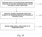
- a video signal decoding device includes a processor, in which the processor determines a result value that indicates a partitioning direction of a current transform block (TB) on the basis of preset conditions, splits the current transform block into a plurality of transform blocks on the basis of the result value, and decodes a video signal by using the plurality of transform blocks, and the preset conditions include a condition related to a color component of the current transform block.
- the processor determines a result value that indicates a partitioning direction of a current transform block (TB) on the basis of preset conditions, splits the current transform block into a plurality of transform blocks on the basis of the result value, and decodes a video signal by using the plurality of transform blocks, and the preset conditions include a condition related to a color component of the current transform block.
- the preset conditions additionally include a condition related to a result of comparing a width of the current transform block and a maximum transform block width, and the maximum transform block width is determined on the basis of a chroma format related to the current transform block, a color component of the current transform block, and a maximum transform size.
- the preset methods additionally includes a condition related to a result of comparing a first width value that is a value obtained by multiplying the width of the current transform block by a first value, and a first height value that is a value obtained by multiplying a height of the current transform block by a second value, the first value and the second value are values related to the width of the current transform block and the height of the current transform block, respectively, and the first value and the second value are respectively set to 1 if the color component of the current transform block is luma, and are respectively determined on the basis of the chroma format related to the current transform block if the color component of the current transform block is chroma.
- the result value is determined to be 1, which is a value indicating that the partitioning direction is a vertical direction
- a width of each of the plurality of transform blocks is a value obtained by dividing the width of the transform block by 2
- a height of each of the plurality of transform blocks is the same as the height of the transform block.
- the result value is determined to be 0, which is a value indicating that the partitioning direction is a horizontal direction
- a width of each of the plurality of transform blocks is the same as the width of the transform block
- a height of each of the plurality of transform blocks is a value obtained by dividing the height of the transform block by 2.
- the maximum transform size is 32.
- a video signal encoding device includes a processor, in which the processor determines a result value that indicates a partitioning direction of a current transform block (TB) on the basis of preset conditions, splits the current transform block into a plurality of transform blocks on the basis of the result value, and generates a bitstream including information on the plurality of transform blocks, and the preset conditions include a condition related to a color component of the current transform block.
- the processor determines a result value that indicates a partitioning direction of a current transform block (TB) on the basis of preset conditions, splits the current transform block into a plurality of transform blocks on the basis of the result value, and generates a bitstream including information on the plurality of transform blocks
- the preset conditions include a condition related to a color component of the current transform block.
- the preset conditions additionally include a condition related to a result of comparing a width of the current transform block and a maximum transform block width, and the maximum transform block width is determined on the basis of a chroma format related to the current transform block, a color component of the current transform block, and a maximum transform size.
- the preset methods additionally includes a condition related to a result of comparing a first width value that is a value obtained by multiplying the width of the current transform block by a first value, and a first height value that is a value obtained by multiplying a height of the current transform block by a second value, the first value and the second value are values related to the width of the current transform block and the height of the current transform block, respectively, and the first value and the second value are respectively set to 1 if the color component of the current transform block is luma, and are respectively determined on the basis of the chroma format related to the current transform block if the color component of the current transform block is chroma.
- the result value is determined to be 1, which is a value indicating that the partitioning direction is a vertical direction
- a width of each of the plurality of transform blocks is a value obtained by dividing the width of the transform block by 2
- a height of each of the plurality of transform blocks is the same as the height of the transform block.
- the result value is determined to be 0, which is a value indicating that the partitioning direction is a horizontal direction
- a width of each of the plurality of transform blocks is the same as the width of the transform block
- a height of each of the plurality of transform blocks is a value obtained by dividing the height of the transform block by 2.
- the reference samples may be samples included in a neighboring block of the current block.
- the reference samples may be samples adjacent to a left boundary of the current block and/or samples may be samples adjacent to an upper boundary.
- the reference samples may be samples located on a line within a predetermined distance from the left boundary of the current block and/or samples located on a line within a predetermined distance from the upper boundary of the current block among the samples of neighboring blocks of the current block.
- the neighboring block of the current block may include the left (L) block, the upper (A) block, the below left (BL) block, the above right (AR) block, or the above left (AL) block.
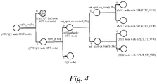
- FIG. 4 illustrates an embodiment of a method of signaling splitting of the quad tree and multi-type tree.
- Preset flags can be used to signal the splitting of the quad tree and multi-type tree described above.
- 'split_cu_flag' which is a flag indicating whether or not to split the current node, can be signaled first.
- the value of 'split_cu_flag' is 0, it indicates that the current node is not split, and the current node becomes a coding unit.
- the coding tree unit includes one unsplit coding unit.
- the current node is a quad tree node 'QT node', the current node is a leaf node 'QT leaf node' of the quad tree and becomes the coding unit.
- the current node is a multi-type tree node 'MTT node', the current node is a leaf node 'MTT leaf node' of the multi-type tree and becomes the coding unit.
- a coding tree unit is a root node of the quad tree, and can be split into a quad tree structure first.
- 'split_qt_flag' is signaled for each node 'QT node'.
- quad tree splitting can be limited according to the type of the current node. Quad tree splitting can be allowed when the current node is the coding tree unit (root node of the quad tree) or the quad tree node, and quad tree splitting may not be allowed when the current node is the multi-type tree node.
- Each quad tree leaf node 'QT leaf node' can be further split into a multi-type tree structure.
- 'split_qt_flag' when 'split_qt_flag' is 0, the current node can be split into multi-type nodes.
- 'mtt_split_cu_vertical_flag' and 'mtt_split_cu_binary_flag' can be signaled.
- 'mtt_split_cu_vertical_flag' When the value of 'mtt_split_cu_vertical_flag' is 1, vertical splitting of the node 'MTT node' is indicated, and when the value of 'mtt_split_cu_vertical_flag' is 0, horizontal splitting of the node 'MTT node' is indicated.
- Picture prediction (motion compensation) for coding is performed on a coding unit that is no longer divided (i.e., a leaf node of a coding unit tree).
- a coding unit that is no longer divided (i.e., a leaf node of a coding unit tree).
- the basic unit for performing the prediction will be referred to as a "prediction unit” or a "prediction block”.
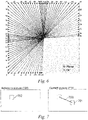
- the angle mode may indicate an angle within an angle range (i.e., a first angular range) between 45 degrees and -135 degrees clockwise.
- the angle mode may be defined based on the 12 o'clock direction.
- the intra prediction mode index 2 indicates a horizontal diagonal (HDIA) mode
- the intra prediction mode index 18 indicates a horizontal (Horizontal, HOR) mode
- the intra prediction mode index 34 indicates a diagonal (DIA) mode
- the intra prediction mode index 50 indicates a vertical (VER) mode
- the intra prediction mode index 66 indicates a vertical diagonal (VDIA) mode.
- the preset angle range can be set differently depending on a shape of the current block. For example, if the current block is a rectangular block, a wide angle mode indicating an angle exceeding 45 degrees or less than -135 degrees in a clockwise direction can be additionally used. When the current block is a horizontal block, an angle mode can indicate an angle within an angle range (i.e., a second angle range) between (45 + offset1) degrees and (-135 + offset1) degrees in a clockwise direction. In this case, angle modes 67 to 76 outside the first angle range can be additionally used.
- the angle mode can indicate an angle within an angle range (i.e., a third angle range) between (45 - offset2) degrees and (-135 - offset2) degrees in a clockwise direction.
- angle modes -10 to -1 outside the first angle range can be additionally used.
- values of offset1 and offset2 can be determined differently depending on a ratio between the width and height of the rectangular block.
- offset1 and offset2 can be positive numbers.
- the basic angle mode is a mode corresponding to an angle used in intra prediction of the existing high efficiency video coding (HEVC) standard
- the extended angle mode can be a mode corresponding to an angle newly added in intra prediction of the next generation video codec standard.
- the basic angle mode can be an angle mode corresponding to any one of the intra prediction modes ⁇ 2, 4, 6, ..., 66 ⁇
- the extended angle mode can be an angle mode corresponding to any one of the intra prediction modes ⁇ 3, 5, 7, ..., 65 ⁇ . That is, the extended angle mode can be an angle mode between basic angle modes within the first angle range. Accordingly, the angle indicated by the extended angle mode can be determined on the basis of the angle indicated by the basic angle mode.
- the spacing between the extended angle modes can be set on the basis of the spacing between the corresponding basic angle modes.
- the spacing between the extended angle modes ⁇ 3, 5, 7, ..., 65 ⁇ can be determined on the basis of the spacing between the corresponding basic angle modes ⁇ 2, 4, 6,... , 66 ⁇ .
- the spacing between the extended angle modes ⁇ -10, -9, ... , -1 ⁇ can be determined on the basis of the spacing between corresponding basic angle modes ⁇ 56, 57,... , 65 ⁇ on the opposite side
- the spacing between the extended angle modes ⁇ 67, 68, ..., 76 ⁇ can be determined on the basis of the spacing between the corresponding basic angle modes ⁇ 3, 4, ... , 12 ⁇ on the opposite side.
- the angular spacing between the extended angle modes can be set to be the same as the angular spacing between the corresponding basic angle modes.
- the number of extended angle modes in the intra prediction mode set can be set to be less than or equal to the number of basic angle modes.
- the extended angle mode can be signaled based on the basic angle mode.
- the wide angle mode i.e., the extended angle mode
- the basic angle mode to be replaced can be a corresponding angle mode on a side opposite to the wide angle mode. That is, the basic angle mode to be replaced is an angle mode that corresponds to an angle in an opposite direction to the angle indicated by the wide angle mode or that corresponds to an angle that differs by a preset offset index from the angle in the opposite direction.
- the preset offset index is 1.
- the extended angle mode can be used for intra prediction of the current block, otherwise, only the basic angle mode can be used for intra prediction of the current block.
- the extended angle mode can be used for intra prediction of the current block, and when the current block is a square block, only the basic angle mode can be used for intra prediction of the current block.
- the inter prediction method described herein may include a general inter prediction method optimized for translation motion and an affine model-based inter prediction method.
- the motion vector may include at least one of a general motion vector for motion compensation according to the general inter prediction method and a control point motion vector for affine motion compensation.
- one or more sets of motion information may be signaled.
- the similarity between the motion information sets for motion compensation of each of the plurality of blocks may be used.
- the motion information set used for prediction of the current block may be derived from the motion information set used for prediction of any one of other previously reconstructed samples. In this way, the encoder and decoder may reduce signaling overhead.
- various embodiments in which the motion information set of the current block is signaled will be described.
- FIG. 8 is a diagram illustrating a method of signaling the motion vector of the current block according to an embodiment of the present invention.
- the motion vector of the current block may be derived from a motion vector predictor (MVP) of the current block.
- MVP motion vector predictor
- the motion vector predictor referenced to derive the motion vector of the current block may be obtained using the motion vector predictor (MVP) candidate list.
- the MVP candidate list may include a preset number of MVP candidates (Candidate 1, Candidate 2, ..., Candidate N).
- a rounding process may be performed on MVP candidates included in the MVP candidate list of the current block.
- resolution of a motion vector difference value of the current block which will be described later, may be used.
- each of the MVP candidates of the current block may be rounded on the basis of the resolution of the motion vector difference value of the current block.
- an encoder 810 and a decoder 820 may construct the MVP candidate list for motion compensation of the current block. For example, among samples reconstructed before the current block, candidates corresponding to samples that are likely to have been predicted on the basis of the same or similar motion information set to the motion information set of the current block may exist.
- the encoder 810 and the decoder 820 may construct the MVP candidate list of the current block on the basis of the plurality of candidate blocks.
- the encoder 810 and the decoder 820 may construct the MVP candidate list according to a predefined rule between the encoder 810 and the decoder 820. That is, the MVP candidate lists respectively constructed in the encoder 810 and the decoder 820 may be identical to each other.
- the decoder 820 may derive the motion vector of the current block on the basis of any one of at least one MVP candidate included in the MVP candidate list of the current block.
- the encoder 810 may signal an MVP index indicating a motion vector predictor to be referenced to derive the motion vector of the current block.
- the decoder 820 may obtain the motion vector predictor of the current block on the basis of the signaled MVP index.
- the decoder 820 may derive the motion vector of the current block using the motion vector predictor.
- the decoder 820 may use the motion vector predictor obtained from the MVP candidate list as the motion vector of the current block without a separate motion vector difference value.
- the decoder 820 may reconstruct the current block on the basis of the motion vector of the current block.
- the inter prediction mode in which the motion vector predictor obtained from the MVP candidate list is used as the motion vector of the current block without the separate motion vector difference value may be referred to as a merge mode.
- a reference picture index for motion compensation of the current block may be signaled.
- the encoder 810 may signal the reference picture index indicating a reference picture including the reference block.
- the decoder 820 may obtain the POC of the reference picture to be referenced for reconstruction of the current block on the basis of the signaled reference picture index.
- the POC of the reference picture may be different from the POC of the reference picture corresponding to the MVP referenced to derive the motion vector of the current block.
- the decoder 820 may perform motion vector scaling. That is, the decoder 820 may obtain MVP' by scaling the MVP.
- the motion vector of the current block may be obtained by summing the motion vector predictor of the current block and the motion vector difference value.
- the motion vector difference value may be signaled from the encoder.
- the encoder may encode the motion vector difference value to generate and signal information representing the motion vector difference value.
- a second flag abs_mvd_greater0_flag indicating whether the absolute value of the motion vector difference value is greater than '0' may be signaled.
- the second flag abs_mvd_greater0_flag[] indicates that the absolute value of the motion vector difference value is not greater than '0'
- the absolute value of the motion vector difference value may be '0'.
- the decoder may obtain the absolute value of the motion vector difference value using other information about the motion vector difference value.
- a third flag abs_mvd_greaterl_flag indicating whether the absolute value of the motion vector difference value is greater than '1' may be signaled.
- the decoder may determine that the absolute value of the motion vector difference value is '1'.
- the decoder may obtain the absolute value of the motion vector difference value using another information about the motion vector difference value. For example, a value of abs_mvd_minus2 (absolute value of motion vector difference value - 2) may be signaled. This is because, when the absolute value of the motion vector difference value is greater than '1', the absolute value of the motion vector difference value may be a value of 2 or more.
- the sign of the motion vector difference value may be signaled through a sign flag mvd_sign_flag. Meanwhile, the sign of the motion vector difference value may be implicitly signaled by sign-bit-hiding.
- the resolution of the motion vector difference value may be set to a different value for each unit of at least one of a block, a coding unit, a slice, or a tile.
- first resolution of the motion vector difference value of the first block may be a unit of 1/4 sample.
- '64' which is a value obtained by dividing the absolute value '16' of the motion vector difference value by the first resolution
- second resolution of the motion vector difference value of the second block may be an integer sample unit.
- '16' which is a value obtained by dividing the absolute value '16' of the second motion vector difference value by the second resolution, may be signaled.
- the resolution of the motion vector difference value of the current block When a relatively small value is used as the resolution of the motion vector difference value of the current block (i.e., when precision is high), it may be advantageous to more precisely represent the motion vector difference value of the current block. However, in this case, since the signaled value itself becomes large, the signaling overhead for the motion vector difference value of the current block may increase. In contrast, when a relatively large value is used as the resolution of the motion vector difference value of the current block (i.e., when the precision is low), the signaling overhead for the motion vector difference value may be reduced by reducing the magnitude of the signaled value.
- the encoder and the decoder may select an advantageous resolution for signaling the motion vector difference value depending on the situation from among a plurality of resolutions.
- the encoder may signal the selected resolution on the basis of the situation.
- the decoder may obtain the motion vector difference value of the current block on the basis of the signaled resolution.
- the resolution of the motion vector difference value of the current block may be any one of a plurality of available resolutions included in a resolution set.
- the plurality of available resolutions may indicate resolutions usable in specific situations.
- the type and number of available resolutions included in the resolution set may vary depending on the situation.
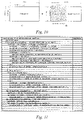
- FIG. 10(a) is a diagram illustrating the coding unit according to an embodiment of the present invention
- FIG. 10(b) is a diagram illustrating the transform unit according to an embodiment of the present invention.
- a block unit on which transform is performed may exist.
- the block unit on which transform is performed may be less than or equal to a coding unit (CU), or may be less than or equal to a block unit on which prediction is performed.
- the size of the block unit on which transform is performed may be limited by a maximum transform size.
- the width or height of the block unit on which transform is performed may be limited by the maximum transform size.
- the width or height of the block unit on which the transform is performed may be less than or equal to the maximum transform size.
- the maximum transform size may vary depending on a chrominance component of the transform block, that is, a luma component and a chroma component.
- the block unit on which the transform is performed may be expressed as a transform unit (TU).
- the coding unit or prediction unit (PU) is greater than the maximum transform size
- the coding unit or the prediction unit may be partitioned to generate a plurality of transform units.
- a transform unit greater than the maximum transform size among the plurality of transform units may be split, and a plurality of transform units may be generated.
- the sizes of the plurality of transform units generated through this process may all be less than or equal to the maximum transform size.
- the fact that the size of the unit (block) is greater than the maximum transform size it may mean that the width or height of the unit (block) is greater than the maximum transform size.
- the size of the unit (block) is less than or equal to the maximum transform size, it may mean that both the width and height of the unit (block) are less than or equal to the maximum transform size.
- the operation of partitioning the transform unit on the basis of the maximum transform size may be performed in situations such as when intra prediction is performed, when processing a residual signal, etc.
- the operation of partitioning the transform unit on the basis of the maximum transform size may be performed recursively, and may be performed until the size of the transform unit becomes less than or equal to the maximum transform size.
- the width and height of the coding unit may be expressed as cbWidth and cbHeight, respectively.
- the width and height of the transform unit may be expressed as tbWidth and tbHeight, respectively.
- the maximum transform size may be expressed as MaxTbSizeY. Specifically, MaxTbSizeY may be a maximum transform size for the luma component. When the size of the transform unit is greater than the maximum transform size and thus the transform unit needs to be split, tbWidth and tbHeight of the transform unit before partitioning may be cbWidth and cbHeight, respectively.
- the transform unit may be partitioned according to whether or not the width or height of the transform unit is greater than the maximum transform size, and tbWidth or tbHeight may be updated.
- cbWidth is greater than MaxTbSizeY.
- the transform unit may be split. Before the transform unit is split, tbWidth and tbHeight of the transform unit may be cbWidth and cbHeight, respectively.
- the TU since tbWidth is greater than MaxTbSizeY, the TU may be partitioned into transform unit 1 and transform unit 2.
- newTbWidth which is a width of a new transform unit (a width of a transform unit after partitioning) may be tbWidth/2.
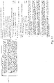
- FIG. 11 is a diagram illustrating transform tree syntax according to an embodiment of the present invention.
- the transform tree syntax illustrated in FIG. 11 may be called from a coding unit syntax or a prediction unit syntax.
- tbWidth and tbHeight which are input values of the transform tree syntax, may be cbWidth and cbHeight described with reference to FIG. 10 .
- the decoder may check whether or not tbWidth is greater than the maximum transform size MaxTbSizeY or tbHeight is greater than MaxTbSizeY. As a result of the check, when tbwidth or tbHeight is greater than MaxTbSizeY, TU partitioning may be performed and the transform tree syntax may be invoked again. Otherwise, the transform unit syntax may be invoked.
- the input values may be updated.
- the input values may be respectively updated to tbWidth/2 and tbHeight/2.
- the updated tbWidth and tbHeight in FIG. 11 may be expressed as trafoWidth and trafoHeight.
- x0 and y0 may be horizontal and vertical coordinate values indicating the position of a block to which the transform tree syntax is applied.
- the decoder may parse a syntax element transform_tree(x0, y0, trafoWidth, trafoHeight, treeType) using values of trafoWidth and trafoHeight.
- tbWidth is greater than MaxTbSizeY
- the decoder may parse a syntax element transform_tree(x0 + trafoWidth, y0, trafoWidth, trafoHeight, treeType).
- tbheight is greater than MaxTbSizeY
- the decoder may parse a syntax element transform_tree(x0, y0 + trafoHeight, trafoWidth, trafoHeight, treeType).
- the decoder may parse a syntax element transform_tree(x0 + trafoWidth, y0 + trafoHeight, trafoWidth, trafoHeight, treeType).
- transform_tree x0 + trafoWidth, y0 + trafoHeight, trafoWidth, trafoHeight, treeType.
- the order of the process in which transform tree syntax 'transform_tree()' is invoked multiple times may be important in terms of encoder, decoder match, or coding performance.
- the order may follow a preset order, and the preset order may be an order according to the syntax disclosed in FIG. 11 .
- the transform tree syntax of FIG. 11 may be parsed regardless of a treeType value.
- the treeType indicates whether a block structure of the luma component and a block structure of the chroma component are the same or different.
- treeType is SINGLE_TREE
- the block structure of the luma component and the block structure of the chroma component may be the same.
- treeType is not SINGLE_TREE
- the block structure of the luma component and the block structure of the chroma component may be different.
- treeType is DUAL_TREE_LUMA
- the block structure of the luma component and the block structure of the chroma component may different.
- treeType may indicate a tree for the luma component or indicate that the transform tree syntax for the luma component is parsed.
- treeType is DUAL_TREE_CHROMA
- the block structure of the luma component and the block structure of the chroma component may be different.
- treeType may indicate a tree for the chroma component or indicate that the transform tree syntax for the chroma component is parsed.
- FIG. 12 is a diagram illustrating a decoding process in the intra block according to an embodiment of the present invention.
- FIG. 12 is a diagram illustrating an explanation of transform unit partitioning and an intra prediction process.
- nTbW Width of the current transform block.
- nTbH Height of the current transform block.
- Clause 8.4.1 disclosed in FIG. 12 shows a decoding process of a luma block and a decoding process of a chroma block of the coding unit.
- the decoding process of the chroma block may include a decoding process of a Cb block and a decoding process of a Cr block.
- different inputs may be used for the decoding process of the luma block and the decoding process of the chroma block, and the decoder may perform the operation disclosed in Clause 8.4.5.1 of FIG. 12 using different inputs.
- cbWidth and cbHeight disclosed in Clause 8.4.1 of FIG. 12 may mean the width and height of the current coding block, and values of cbWidth and cbHeight may be values on the basis of luma samples.
- the chroma block size may be 8x8 according to the chroma format.
- the values of cbWidth and cbHeight for the chroma coding block may be 16 and 16, respectively.
- (xCb, yCb) disclosed in FIG. 12 may indicate the coordinates of the current coding block, or may be the coordinate values of the top-left sample of the current coding block. In this case, the coordinate value may be set on the basis of the coordinates of the top-left sample of the current picture.
- (xCb, yCb) may be a value expressed on the basis of the luma sample.
- the decoder may perform a decoding process on the luma block.
- Clause 8.4.5.1 disclosed in FIG. 12 may be invoked, a sample position input at that time may be (xCb, yCb), and the width and height of the block may be cbWidth and cbHeight, respectively.
- a value of cIdx indicating the color component may be 0.
- the decoder may perform a decoding process on the chroma block.
- Clause 8.4.5.1 disclosed in FIG. 12 may be invoked, and may be invoked for each of the Cb block and the Cr block.
- the sample position input may be (xCb/SubWidthC, yCb/SubHeightC), and the width and height of the block may be cbWidth/SubWidthC and cbHeight/SubHeightC, respectively.
- the value of cIdx may not be 0, and the value of cIdx may be set to 1 for the Cb block and 2 for the Cr block.
- SubWidthC and SubHeightC may be preset values on the basis of the chroma format.
- the values of SubWidthC and SubHeightC may be 1 or 2, and may be values for the relationship between the luma component and the chroma component. SubWidthC and SubHeightC will be described later with reference to FIGS. 14 to 15 .
- inputs may be in a converted state to correspond to the luma block and the chroma block.
- the block width nTbW, block height nTbH, and sample position coordinates (xTbO, yTbO) disclosed in Clause 8.4.5.1 of FIG. 12 may be determined based on the number of chroma samples when the decoding process for the chroma block is performed, and may be determined on the basis of the number of luma samples when the decoding process for the luma block is performed.
- the TU partitioning described above may be performed through Clause 8.4.5.1 of FIG. 12 .
- the maxTbWidth and maxTbHeight disclosed in FIG. 12 are values indicating maximum transform sizes corresponding to the color component, and may be values corresponding to a width and a height, respectively.
- MaxTbSizeY may be the maximum transform size for the luma block. Therefore, for the chroma block (i.e., when cIdx is not 0), maxTbWidth may be MaxTbSizeY/SubWidthC, and maxTbHeight may be MaxTbSizeY/SubHeightC.
- maxTbWidth and maxTbHeight may both be MaxTbSizeY.
- the coordinates (xTbY, yTbY) may be converted on the basis of luma, and in this case, the coordinates may be calculated on the basis of cIdx, SubWidthC, and SubHeightC.
- the decoding process described in FIG. 12 should match the syntax structure. That is, the decoding process of FIG. 12 should match the syntax structure of FIG. 11 .
- steps 1 to 5 disclosed in Clause 8.4.5.1 of FIG. 12 may be performed.
- the width nTbW and height nTbH of a block may be updated with newTbW and newTbH. Specifically, if nTbW is greater than maxTbWidth, the width of the block is updated to nTbW/2, otherwise, the width of the block remains nTbW.
- section 8.4.5.1 of FIG. 12 may be invoked again by using coordinates (xTbO, yTbO + newTbH), newTbW, and newTbH as inputs.
- section 8.4.5.1 of FIG. 12 may be invoked again by using coordinates (xTbO, yTbO + newTbH), newTbW, and newTbH as inputs.
- Clause 8.4.5. of FIG. 12 may be invoked again by using coordinates (xTbO + newTbW, yTbO + newTbH), newTbW, and newTbH as inputs.
- Steps 2 to 5 of FIG. 12 may be the same as the process of invoking the transform tree syntax again in FIG. 11 .
- a process other than steps 1 to 5 of FIG. 12 may be performed.
- the process other than steps 1 to 5 of FIG. 12 may be a process related to actual intra prediction, residual signal decoding, transform, and reconstruction.
- FIG. 13 is a diagram illustrating a decoding process of a residual signal according to an embodiment of the present invention.
- FIG. 13 may be performed when inter prediction, intra block copy (IBC) prediction, etc. are applied.
- FIG. 13 may disclose the TU partitioning described above.
- the step of invoking section 8.5.8 of FIG. 13 may be performed for each color component.
- the decoding process of Clause 8.5.8 of FIG. 13 may be performed using the inputs corresponding to each color component.
- the cIdx value indicating the color component may be set to 0 when the block is the luma component, and set to a value other than 0 when the block is the chroma component. For example, when the block is a Cb component, the cIdx value may be set to 1, and when the block is a Cr component, the cIdx value may be set to 2.
- (xTbO, yTbO), nTbW, and nTbH may be values corresponding to each color component. That is, (xTbO, yTbO), nTbW, and nTbH may be values corresponding to the number of samples of each color component.
- the maximum transform size may be adaptively calculated for each color component.
- the width of the block or the height of the block is updated on the basis of whether or not nTbW or nTbH is greater than the maximum transform size, and may be described as newTbW and newTbH.
- Steps 2 to 5 of Clause 8.5.8 of FIG. 13 disclose a process of invoking Clause 8.5.8 again, which may be the same as the contents described above with reference to FIG. 12 .
- nTbW is less than or equal to maxTbWidth and nTbH is less than or equal to and maxTbHeight
- a process other than steps 1 to 5 of FIG. 13 may be performed.
- the process other than steps 1 to 5 of FIG. 13 may be the process related to actual residual signal decoding, transform, etc.
- FIG. 14 is a diagram illustrating a relationship between color components according to an embodiment of the present invention.
- elements related to the color components may include chroma_format_idc, Chroma format, separate_colour_plane_flag, etc.
- Chroma format when Chroma format is Monochrome, only one sample array may exist, and SubWidthC and SubHeightC may both be 1.
- Chroma format is 4:2:0 sampling, two chroma arrays may exist. In this case, the chroma array may have a half width and a half height of a luma array, and SubWidthC and SubHeightC may both be 2.
- Chroma format is 4:2:2 sampling
- two chroma arrays may exist. In this case, the chroma array may have a half width of the luma array and the same height as the luma array, and SubWidthC and SubHeightC may be 2 and 1, respectively.
- Chroma format is 4:4:4 sampling
- two chroma arrays may exist.
- the chroma array may have the same width and the same height as the luma array, and SubWidthC and SubHeightC may both be 1.
- Chroma format is 4:4:4 sampling
- a process performed on the basis of separate_colour_plane_flag may be different.
- the chroma array may have the same width and the same height as the luma array.
- separate_colour_plane_flag 1, processes for three color planes, i.e., luma, Cb, and Cr, may be performed, respectively.
- separate_colour_plane_flag is 1, only one color component may exist in one slice.
- separate_colour_plane_flag is 0, a plurality of color components may exist in one slice.
- SubWidthC and SubHeightC may both be 1 regardless of separate_colour_plane_flag.
- SubWidthC and SubHeightC may indicate how large the chroma array is compared to the luma array, when the chroma array width or chroma array height is half of the luma array, SubWidthC or SubHeightC may be 2, and when the chroma array width or height is the same size as the luma array, SubWidthC or SubHeightC may be 1.
- SubWidthC and SubHeightC may have different values only when Chroma format is 4:2:2 sampling. Therefore, when Chroma format is 4:2:2 sampling, a relationship between a width and a height on the basis of the luma component may be different from the relationship between the width and the height on the basis of the chroma component.
- FIG. 15 is a diagram illustrating a relationship between the color components according to an embodiment of the present invention.
- FIG. 15(a) illustrates a case where Chroma format is 4:2:0 sampling
- FIG. 15(b) illustrates a case where Chroma format is 4:2:2 sampling
- FIG. 15(c) illustrates a case where Chroma format is 4:4:4 sampling.
- one chroma sample (one Cb, one Cr) per two luma samples may be positioned in the horizontal direction.
- one chroma sample (one Cb, one Cr) may be positioned per two luma samples in a vertical direction.
- one chroma sample when Chroma format is 4:2:2 sampling, one chroma sample (one Cb, one Cr) may be positioned per two luma samples in the horizontal direction. In addition, one chroma sample (one Cb, one Cr) may be positioned per a luma sample in the vertical direction.
- one chroma sample when Chroma format is 4:4:4 sampling, one chroma sample (one Cb, one Cr) may be positioned per a luma sample in the horizontal direction. In addition, one chroma sample (one Cb, one Cr) may be positioned per a luma sample in the vertical direction.
- SubWidthC and SubHeightC described above may be determined according to the relationship between the luma sample and the chroma sample illustrated in FIG. 15 , and transformation based on the luma sample and the transform based on the chroma sample may be performed on the basis of SubWidthC and SubHeightC.
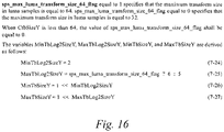
- FIG. 16 is a diagram illustrating a maximum transform size according to an embodiment of the present invention.
- the maximum transform size may be variable, and the complexity of the encoder or decoder may be adjusted by changing the maximum transform size. For example, when the maximum transform size is small, the complexity of the encoder or decoder may be reduced.
- a value that may be the maximum transform size may be limited.
- the maximum transform size may be limited to either of two values.
- the two values may be 32 or 64, and may be the size based on luma.
- the maximum transform size may be signaled at a higher level.
- the higher level may be a level including the current block.
- a unit such as a sequence, a sequence parameter, a slice, a tile, a tile group, a picture, and a coding tree unit (CTU) may be the higher level.
- CTU coding tree unit
- the syntax and decoding process described in FIGS. 11 to 13 may be used. Specifically, when the maximum size of the CU or PU is 128 and the maximum transform size is 64, the embodiments of FIGS. 11 to 13 may be used. In this case, if the CU or PU is greater than the maximum transform size and thus the TU is split, the TU may be partitioned into two or four. In the partitioning, the TU may be partitioned into up to two TUs in each of the horizontal direction and the vertical direction.
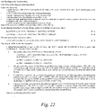
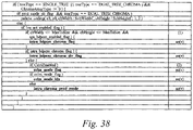
- verSplitFirst when tbWidth is greater than or equal to MaxTbSizeY and tbWidth is greater than or equal to tbHeight, verSplitFirst may be set to 1, otherwise verSplitFirst may be set to 0.
- nTbW and nTbH of the decoding process disclosed in FIG. 22 may be 8 and 8, respectively, for the chroma block (when cIdx is not 0).
- the TB when a TB is split, the TB may be partitioned on the basis of nTbW, nTbH, MaxTbSizeY, cIdx, SubWidthC, and SubHeightC.
- the TB when the TB is split, the TB may be partitioned on the basis of nTbW, nTbH, maxTbWidth, cIdx, SubWidthC, and SubHeightC.
- the TB may be partitioned on the basis of the verSplitFirst value.
- newTbW and newTbH may be determined on the basis of the verSplitFirst value. For example, when verSplitFirst is 1, newTbW may be determined as nTbW/2, and newTbH may be determined as nTbH. When verSplitFirst is 0, newTbW may be determined as nTbW, and newTbH may be determined as nTbH/2.
- step 3 of FIG. 22 the decoding process may be invoked again using the position of block (xTbO + newTbW, yTbO), newTbW, and newTbH. This may be for the second (right) TU of the partitioned TUs like the right TU(2) part of FIG. 19 .
- CtbSizeY is 32
- CtbSizeY is 32
- the value of sps_max_luma_transform_size_64_flag may be inferred to be equal to 0, and thus the maximum transform size (MaxTbSizeY) value may be determined as 32.
- sps_sbt_enabled_flag when the value of sps_sbt_enabled_flag is 1 and the value of sps_max_luma_tranform_size_64_flag is 1 (that is, sps_sbt_enabled_flag && sps_max_luma_tranform_size_64_flag), sps_sbt_max_size_64_flag is signaled, otherwise sps_sbt_max_size_64_flag is not signaled.
- the value of sps_sbt_max_size_64_flag may be inferred to be equal to 0.
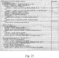
- FIG. 25 is a diagram illustrating a transform tree syntax according to an embodiment of the present invention.
- values based on luma may be used for the inputs of the transform tree syntax 'transform_tree()'.
- values based on the chroma component may be used. That is, it is possible to compare tbWidth/SubWidthC and tbHeight/SubHeightC. Specifically, it is possible to check whether tbWidth/SubWidthC is greater than tbHeight/SubHeightC.
- TU partitioning for the chroma component may be performed on the same basis as when the luma component is used for TU partitioning.
- the decoder may determine verSplitFirst by performing step (1) of FIG. 25 . That is, the partitioning may be determined using the value based on the luma component.
- the decoder may determine verSplitFirst by performing step (2) of FIG. 25 . That is, the partitioning may be determined using the value based on the chroma component.
- FIG. 26 is a diagram illustrating a decoding process according to an embodiment of the present invention.
- verSplitFirst may be determined by using the width of the block and the height of the block based on the luma component.
- verSplitFirst may be determined by comparing whether nTbW is greater than nTbH. That is, verSplitFirst may be determined without using SubWidthC and SubHeightC.
- verSplitFirst may be determined by comparing whether nTbW/SubWidthC is greater than nTbH/SubHeightC.
- a maximum transform skip size may be less than the maximum transform size. For example, if the maximum transform size is variable, the maximum transform skip size may vary accordingly. Therefore, when the maximum transform size is variable, a method of signaling the maximum transform skip size may vary accordingly.
- the max transform size and max transform skip size may be the same.
- whether or not transform skip is used for the partitioned TUs may be shared.
- signaling of a syntax element indicating whether or not transform skip is used for the partitioned TUs may be partially omitted. This is because, when the size of the CU or PU is greater than the maximum transform size, the residual signal shapes of the partitioned TUs may be similar.
- Whether or not transform skip is used in the partitioned TUs is shared or omitting of signaling of a related syntax element may be limited to a case where the maximum transform size and the maximum transform skip size are the same when a variable maximum transform size and a variable maximum transform skip size are used.
- Whether or not transform skip is used is shared among additionally partitioned TUs may be limited to a case where transform skip is used for a TU serving as a reference, e.g., the first TU. That is, when transform skip is not used for the TU serving as the reference, whether or not transform skip is used may be signaled to other partitioned TUs.
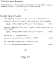
- FIG. 27 is a diagram illustrating a method of performing BDPCM according to an embodiment of the present invention.
- BDPCM may be described as quantized residual differential pulse coded modulation (RDPCM).
- a syntax element indicating whether or not BDPCM is used may exist.
- the syntax element may be BdpcmFlag or intra_bdpcm_flag. Signaling of the syntax element indicating whether or not BDPCM is used may be performed at the CU level.
- a syntax element at a higher level indicating whether or not BDPCM may be used may exist.
- the syntax element at the higher level indicating whether or not BDPCM is used may be sps_bdpcm_enabled_flag.
- the higher level at which the syntax element is signaled may be an SPS level, a slice level, a tile level, or a tile group level.
- prediction samples corresponding to the same row may have the same value.
- a value of a prediction sample at a certain location may be the same value as a reference sample corresponding to the upper part of the certain location in the vertical mode.
- prediction samples corresponding to the same column i.e., prediction samples having the same x-coordinate
- FIG. 27(a) is a diagram for prediction mode derivation of BDPCM.
- prediction mode derivation of BDPCM may be based on BdpcmDir.
- IntraPredModeY may be a value indicating a prediction mode.
- IntraPredModeY may be a value indicating the prediction mode for the luma component.
- IntraPredModeY may be set to INTRA_ANGULAR50 or INTRA_ANGULAR18 on the basis of BdpcmDir.
- IntraPredModeY When the value of BdpcmDir is 1, IntraPredModeY is set to INTRA_ANGULAR50, and may be a vertical mode. In addition, when the value of BdpcmDir is 0, IntraPredModeY is set to INTRA_ANGULAR18, and may be a horizontal mode. A prediction operation may be performed on the basis of IntraPredModeY.
- a residual signal generation method or a scaling and transform method for BDPCM may exist.
- a value based on a difference between specific values may be coded and signaled.
- a value on the basis of a difference between a residual signal and a value based on the residual signal may be coded and signaled.
- the signaled value corresponding to a sample of a first position may be a difference between a value of a second position based on the first position and a value of the first position.
- the signaled value corresponding to the sample of the first position may be a difference between the value of the first position and the value of the second position, which is a position adjacent to the first position.
- a signaled value corresponding to a sample of a first position (x, y) may be a difference between a value of a second position (x-1, y) and the value of the first position in the horizontal mode.
- the signaled value corresponding to the sample of the first position (x, y) may be a difference between a value of a second position (x, y-1) and the value of the first position in the vertical mode.
- the value of the second position and the value of the first position may be the residual signal or the value based on the residual signal
- FIG. 27(b) is a diagram illustrating an operation in the decoder when BDPCM is used.
- dz may be an array created on the basis of values signaled through a syntax element.
- a dz[x][y] value may be set on the basis of dz[x][y] and dz[x-1][y].
- the dz[x][y] value may be set on the basis of (dz[x-1][y] + dz[x][y]) (see 8-961 in FIG. 27(b) ).
- This setting may be performed when x is greater than 0 (not tangent to the left boundary of the block).
- dz[x][y] may remain as dz[x][y].
- the dz[x][y] value may be set on the basis of dz[x][y] and dz[x][y-1].
- the dz[x][y] value may be set on the basis of (dz[x][y-1] + dz[x][y]) (8-962 in FIG. 27(b) ). This setting may be performed when y is greater than 0 (not tangent to the top boundary of the block).
- dz[x][y] may remain as dz[x][y].
- the reason dz is calculated on the basis of a sum (+) operation is because the signaled signal is performed on the basis a difference (-) operation.
- the signaled signal dz[x][y] may have been a value set to (dz[x][y] - dz[x-1][y]) in the horizontal mode, and may have been a value set to (dz[x][y] - dz[x][y-1]) in the vertical mode. Therefore, in order to reconstruct this, the decoder may perform a calculation based on the sum operation.
- dnc[x][y] may be derived
- d[x][y] may be derived (8-963 and 8-964 in FIG. 27(b) ).
- transform may be performed on the basis of d[x][y].
- performing the transform may include performing a transform skip mode. That is, performing the transform may include not performing an operation based on a transform matrix.
- the transform skip mode may always be used.
- the value of transform_skip_flag which is a syntax element indicating whether or not the transform skip mode is used, may always be 1.
- the residual signal may be determined without a step of multiplying d[x][y] by a vector or a matrix.
- the transform skip mode the residual signal may be determined without performing an operation on d[x][y] except for a bit shift or rounding.
- the (d[x] [y] « tsShift) value may be r[x][y] which is a residual sample array value.
- tsShift may be a value determined on the basis of the width and height of the transform block.
- an intermediate residual sample and a residual sample may be determined on the basis of r[x][y].
- BDPCM may be usable only when the transform skip mode is applied. This is because the transform skip mode is usable when BDPCM is used. For example, only when the syntax element signaled at the higher level indicates that the transform skip mode is usable, signaling of the syntax element at the higher level indicating that the BDPCM is usable may be performed.
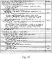
- FIG. 28 is a diagram illustrating syntax related to BDPCM according to an embodiment of the present invention.
- BDPCM When a syntax element signaled at a higher level indicating whether or not BDPCM is usable indicates that BDPCM is usable, BDPCM may be used. Referring to FIG. 28 , whether or not to parse intra_bdpcm_flag may be determined on the basis of sps_bdpcm_enabled_flag.
- the block size for which transform skip may be used may be limited.
- the maximum value of the width or height of a block that transform skip may be used may be MaxTsSize. Therefore, when the width of the block is less than or equal to MaxTsSize and the height of the block is less than or equal to MaxTsSize, the transform skip may be used. On the other hand, if the width of the block is greater than MaxTsSize or the height of the block is greater than MaxTsSize, skip transform may not be used. Since transform is performed at the TU level, the width and height of the block may be the width and height of the transform block.
- the width of the transform block may be described as tbWidth, and the height of the transform block may be described as tbHeight. Since BDPCM uses a transform skip, whether or not BDPCM is usable may be determined on the basis of MaxTsSize. In addition, whether or not BDPCM is usable may be signaled at the CU level. Therefore, whether or not to use BDPCM may be determined on the basis of the width and height (which may be described as cbWidth and cbHeight) of the coding block (CB) and MaxTsSize.
- MaxTsSize may be selected and used as any one of a plurality of values.
- MaxTsSize may be a value of 32 or less.
- MaxTsSize may be a value less than or equal to MaxTbSizeY.
- MaxTsSize may be one of 32, 16, 8, or 4.
- a syntax element for determining MaxTsSize may exist. For example, a value based on Log2 (MaxTsSize) may be signaled. log2_transform_skip_max_size_minusN may be signaled, and MaxTsSize may be (1 ⁇ (log2_transform_skip_max_size_minusN + N)).
- N may be 2, in this case, log2_transform_skip_max_size_minus2 is signaled, and MaxTsSize may be (1 ⁇ (log2_transform_skip_max_size_minus2 + 2)).
- log2_transform_skip_max_size_minus2 may be a value ranging from 0 to 3
- MaxTsSize may be one of 4, 8, 16, and 32.
- the syntax element for determining MaxTsSize may be signaled at a higher level. For example, the syntax element may be signaled at a picture parameter set or slice level.
- FIG. 29 is a diagram illustrating a BDPCM usable condition according to an embodiment of the present invention.
- MaxTbSizeY is 64 and MaxTsSize is 32 or less
- cbWidth is MaxTsSize or less
- cbHeight is MaxTsSize or less
- cb Width may be equal to tbWidth
- cbHeight may be equal to tbHeight. Therefore, the fact that BDPCM is usable when cbWidth and cbHeight are MaxTsSize or less may mean that BDPCM is usable when tbWidth and tbHeight are MaxTsSize or less.
- MaxTbSizeY may be less than or equal to MaxTsSize.
- BDPCM may be used. This is because, in this case, TU partitioning may occur, and the width and height of a transform block after TU partitioning are less than or equal to MaxTsSize.
- MaxTbSizeY is equal to MaxTsSize
- cbWidth is greater than MaxTsSize or cbHeight is greater than MaxTsSize
- TU partitioning may occur, and the width and height of the transform block after TU partitioning may be equal to MaxTbSizeY. Therefore, it may be possible to perform the transform skip mode, which is a mode used in the case of BDPCM. This is because the transform skip mode is performed at the TU level.
- intra_bdpcm_flag may be parsed.
- BDPCM may be used even when MaxTbSizeY and MaxTsSize are the same.
- BDPCM may be used when the syntax element signaled at a higher level indicating whether or not BDPCM is usable indicates that BDPCM is usable and MaxTbSizeY and MaxTsSize are the same.
- BDPCM may be used when cbWidth is less than or equal to MaxTsSize and cbHeight is less than or equal to MaxTsSize.
- BDPCM may be used when cbWidth is less than or equal to MaxTsSize and cbHeight is less than or equal to MaxTsSize.
- BDPCM may not be used when cbWidth is greater than MaxTsSize or cbHeight is greater than MaxTsSize.
- intra_bdpcm_flag which is a syntax element indicating whether or not BDPCM is used, may be parsed.
- MaxTbSizeY may have a value of 32 or more. Specifically, MaxTbSizeY may have a value of 32 or 64. In addition, MaxTsSize may have a value of 32 or less. Specifically, MaxTsSize may have a value of 4 or 8 or 16 or 32. Therefore, when MaxTbSizeY and MaxTsSize are the same, MaxTbSizeY may be 32 and MaxTsSize may be 32.
- FIG. 29 (a) and (b) are diagrams illustrating a syntax structure related to the embodiment described above.
- intra_bdpcm_flag when the value of sps_bdpcm_enabled_flag is 1 and at least one of the following two conditions is satisfied, intra_bdpcm_flag may be parsed.
- intra_bdpcm_flag may not be parsed. Meanwhile, when intra_bdpcm_flag does not exist, the value of intra_bdpcm_flag may be inferred to be equal to 0.
- intra_bdpcm_flag when the value of sps_bdpcm_enabled_flag is 1 and at least one of the following two conditions is satisfied, intra_bdpcm_flag may be parsed.
- intra_bdpcm_flag may not be parsed. Meanwhile, when intra_bdpcm_flag does not exist, the value of intra_bdpcm_flag may be inferred to be equal to 0.
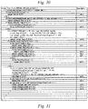
- FIG. 30 is a diagram illustrating CIIP and intra prediction according to an embodiment of the present invention.
- CIIP is an abbreviation of combined inter- and intra- prediction, or CIIP is an abbreviation of combined inter-picture merge and intra-picture prediction.
- CIIP means a method of combining an intra prediction signal and an inter prediction signal when a prediction signal is generated.
- the intra prediction method or the inter prediction method may be limited. For example, when CIIP is used, only a planar mode MODE_PLANAR or only a merge mode may be used for the intra prediction mode.
- intra prediction may be performed on the entire coding block.
- intra prediction when CIIP is used for the CB or CU, intra prediction may be performed on a block having a size of (cbWidth ⁇ cbHeight). In other words, when CIIP is used for the CB or CU, intra prediction may be performed without TU partitioning. Even if the CB is greater than the maximum transform size, intra prediction may be performed without TU partitioning when CIIP is used.
- the block size for which CIIP may be used may be limited.
- the limited block size may be a fixed value.
- the maximum value of the block size for which CIIP may be used may be predetermined. For example, when the width cbWidth or height cbHeigh of a block is 128 or more than 128, CIIP may not be used. When cbWidth is less than 128, cbHeight is less than 128, and cbWidth ⁇ cbHeight is 64 or more, CIIP may be used.
- FIG. 30 illustrates the CIIP mode and the intra prediction mode when the CB or CU is 64x64.
- inter prediction for a block having a size of 64x64 and intra prediction for a block having a size of 64x64 may be performed.
- a predicted block having a size of 64x64 (“Combined inter and intra predicted block" of FIG. 30 ) may be generated on the basis of the inter prediction and the intra prediction.
- a TB to be partitioned from the CB having a size of 64x64 may be determined on the basis of MaxTbSizeY. For example, when MaxTbSizeY is less than 64 (e.g., 32), the CB having a size of 64x64 may be partitioned into TUs having a size of 32x32, and intra prediction may be performed on each of the partitioned TUs. Therefore, four predicted blocks each having a size of 32x32 may be generated.
- the intra prediction in the CIIP mode and the intra prediction in the intra prediction mode are not aligned with each other.
- the intra prediction may be performed on a block having a size greater than 32x32 when the CIIP mode is used, and the intra prediction in the intra prediction mode may be performed on a block having a size less than or equal to 32x32. Therefore, in the case of intra prediction mode, hardware and software having the capability capable of processing intra prediction for blocks having a size less than or equal 32x32 are required, but in the case of CIIP mode, hardware and software having the capability capable of processing intra prediction for blocks having a size greater than the size of 32x32 are required. This may be a huge burden in terms of implementation.
- some encoders intend to limit the maximum transform size to 32 instead of 64 to perform intra prediction on small-sized blocks, and to reduce the hardware and software burdens, but may need to prepare intra prediction for blocks having the size greater than 32 in order to use the CIIP mode.
- FIG. 31 is a diagram illustrating merge data syntax according to an embodiment of the present invention.
- a particular group may contain more than one mode.
- Group 1 may include a subblock merge mode
- Group2 may include a regular merge mode and merge with motion vector difference (MMVD)
- Group3 may include CIIP and a triangle merge mode.
- group_1_flag may be merge_subblock_flag
- group_2_flag may be regular_merge_flag.
- ciip_flag and mmvd_merge_flag may exist as syntax elements indicating a mode within the group.
- the decoder may parse regular_merge_flag.
- a condition for allowing regular_merge_flag to be parsed may exist.
- syntax elements signaled at a higher level indicating whether or not the mode usable may include sps_ciip_enabled_flag and sps_triangle_enabled_flag.
- sps_triangle_enabled_flag may be a syntax element signaled at a higher level indicating whether the decoder may use a triangle mode, and may be signaled from a sequence parameter set. There may also be a condition based on a slice type. In addition, there may be a condition based on cu_skip_flag. In this case, cu_skip_flag may be a syntax element indicating whether or not a skip mode may be used. When the skip mode is used, the residual signal may not be signaled. Therefore, when the skip mode is used, the decoder may reconstruct the block from the prediction signal without the residual signal (or a transform coefficient).
- the decoder may parse regular_merge_flag.
- the value of sps_triangle_enabled_flag is 1, the value of MaxNumTriangleMergeCand is greater than 1, and slice_type is B, if the condition that the block width ⁇ block height is 64 or more is satisfied, the decoder may parse regular_merge_flag.
- the condition that the triangle merge mode may be used may include a case where a value of sps_triangle_enabled_flag is 1, a value of MaxNumTriangleMergeCand is greater than 1, and slice_type is B.
- the condition related to the block size for which the triangular merge mode may be used may include a case where the width of the block ⁇ the height of the block is 64 or more.
- the decoder may parse regular_merge_flag.
- the decoder may not parse regular_merge_flag.
- regular_merge_flag When regular_merge_flag does not exist, the value of regular_merge_flag may be inferred to be equal to 1. In the present invention, when the value of regular_merge_flag is 1, the regular merge mode or MMVD may be used. Therefore, when both the condition related to the block size for which CIIP may be used described above and the condition related to the block size for which the triangular merge mode may be used described above are not satisfied, usable modes may be the regular merge mode and MMVD. In this case, regular_merge_flag may be determined as 1 without being parsed.
- the usable mode may be the regular merge mode or MMVD, and thus regular_merge_flag may be inferred to be equal to 1 without being parsed.
- syntax elements may be parsed on the basis of the value of sps_mmvd_enabled_flag.
- sps_mmvd_enabled_flag may be a syntax element signaled at a higher level indicating whether MMVD is usable.
- MMVD may not be used.
- mmvd_merge_flag when the value of sps_mmvd_enabled_flag is 0, mmvd_merge_flag, mmvd_cand_flag, mmvd_distance_idx, and mmvd_direction_idx may not be parsed.
- mmvd_merge_flag does not exist, the value of mmvd_merge_flag may be inferred to be equal to 0.
- the decoder may parse ciip_flag when both the condition that CIIP may be used described above and the condition that the triangular merge mode may be used described above are satisfied.
- the decoder may parse ciip_flag when both the condition that CIIP may be used described above and the condition that the triangular merge mode may be used described above are satisfied.
- the value of ciip_flag is 1, CIIP may be used, and when the value of ciip_flag is 0, the triangular merge mode may be used.
- the decoder may not parse ciip_flag.
- ciip_flag When ciip_flag does not exist, the value of ciip_flag may be inferred to be equal to 1 when all of the following conditions are satisfied. Meanwhile, if any one of the following conditions is not satisfied, the value of ciip_flag may be inferred to be equal to 0.
- the sps_ciip_enabled_flag may be a syntax element signaled at a higher level indicating whetheror not CIIP is used.
- the sps_ciip_enabled_flag may be signaled from the sequence parameter set.
- general_merge_flag may be a syntax element indicating whether or not a merge mode is used.
- merge_subblock_flag may be a syntax element indicating whether or not a subblock merge mode is used.
- the subblock merge mode may be an affine merge mode or subblock-based temporal motion vector prediction (SbTMVP).
- regular_merge_flag may be a syntax element indicating whether or not an existing merge mode (e.g., regular merge mode) or MMVD is used.
- FIG. 32 is a diagram illustrating merge data syntax according to an embodiment of the present invention.
- the block size for which CIIP may be used is limited, and in this case, the block size may be a fixed value.
- the maximum transform size is variable, there is a problem that intra prediction in the CIIP mode and intra prediction in the intra prediction mode are not aligned with each other.
- a block size for which the CIIP mode may be used may be variable.
- the block size for which the CIIP mode may be used may be based on MaxTbSizeY. For example, when the width of the block is less than or equal to MaxTbSizeY and the height of the block is less than or equal to MaxTbSizeY, the CIIP mode may be used. In addition, when the width of the block is greater than MaxTbSizeY or the height of the block is greater than MaxTbSizeY, the CIIP may not be used.
- the width and height of the block may be the width and height of the coding block (unit). Because the width and height of the block are determined on the basis of MaxTbSizeY, the intra prediction size in the CIIP mode is limited to less than or equal to MaxTbSizeY, and the existing intra prediction size is also limited to less than or equal to MaxTbSizeY, and thus intra prediction may be performed using a unified method, hardware, and software. This has the effect of reducing the resources required for hardware and software. Even when MaxTbSizeY is 32, both intra prediction in the CIIP mode and conventional intra prediction may be performed on a block having a size of 32x32 or less.
- the conditions for allowing the triangle (merge) mode to be used may include a case where the value of sps_triangle_enabled_flag is 1, the value of MaxNumTriangleMergeCand is greater than 1, slice_type is B, and cbWidth ⁇ cbHeight is 64 or more.
- the decoder may parse ciip_flag.
- the decoder may not parse the ciip_flag.
- the ciip_flag value may be inferred to be equal to 0.
- the ciip_flag value may be inferred to be equal to 1.
- the decoder may parse regular_merge_flag.
- the decoder may not parse regular_merge_flag. In this case, if regular_merge_flag does not exist, the value of regular_merge_flag may be inferred as (general_merge_flag && !merge_subblock_flag).
- the decoder may parse regular_merge_flag.
- regular_merge_flag may not be parsed.
- ciip_flag when all of the following conditions are satisfied, the value of ciip_flag may be inferred to be equal to 1. On the other hand, when any one of the following conditions is not satisfied, the value of ciip_flag may be inferred to be equal to 0.
- the decoder may parse regular_merge_flag.
- regular_merge_flag When regular_merge_flag does not exist, the value of regular_merge_flag may be inferred as (general_merge_flag && !merge_subblock_flag). That is, when the value of general_merge_flag is 1 and the value of merge_subblock_flag is 0, the value of regular_merge_flag may be inferred to be equal to 1. On the other hand, when the value of general_merge_flag is 0 or the value of merge_subblock_flag is 1, regular_merge_flag may be inferred to be equal to 0.
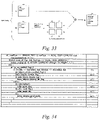
- FIG. 33 is a diagram illustrating a method of performing the CIIP mode according to an embodiment of the present invention.
- FIG. 33 may be a diagram illustrating an embodiment for solving the problem described in FIG. 30 .
- FIG. 33 illustrates a prediction method when the CIIP mode is used for a CU having a size of 64x64 and MaxTbSizeY is 32. Since the CIIP mode is used, a prediction signal may be generated on the basis of a prediction signal for which inter prediction is used and a prediction signal for which intra prediction is used. In this case, inter prediction may be performed on the CU having a size of 64x64. In addition, since a block having a size of 64x64 exceeds MaxTbSizeY, TU partitioning may be performed before intra prediction is performed. Blocks after TU partitioning may be blocks having a size of MaxTbSizeY ⁇ MaxTbSizeY. That is, after TU partitioning, a plurality of blocks having a size of 32x32 may be generated. In addition, intra prediction may be performed on blocks generated after TU partitioning, respectively.
- a reference sample at a location adjacent to each TU may be used after partitioning. Since the reference sample close to the block is used, there is an advantage in terms of prediction performance and also in terms of coding efficiency.
- the reference sample may be a reconstructed sample. However, in this case, in order to perform intra prediction on a specific TU, it is necessary to wait for an adjacent TU (i.e., the TU corresponding to the position of the reference sample) to be reconstructed, and thus unnecessary latency may occur.
- the reference sample may be a predicted sample.
- the prediction performance may be lower than that of using the reconstructed sample, but even if the adjacent TU is not completely reconstructed, if the prediction is completed, prediction of the current TU may start. Therefore, latency may be reduced compared to the case of using the reconstructed sample as the reference sample. However, even if the predicted sample is used as the reference sample, there may be a problem with respect to latency.
- prediction in the CIIP mode may be performed even if the size of a CU is large. This is because intra prediction included in the CIIP mode may be performed on a CU having a large size, and intra prediction included in the CIIP mode may be performed on a partitioned and smaller block after TU partitioning. Therefore, the condition related to the block size for which the CIIP mode may be used may not have an upper limit. That is, the condition that cbWidth is less than 128 and cbHeight is less than 128 described in FIGS. 31 to 32 may not exist.
- the decoder may parse ciip_flag or regular_merge_flag.
- the decoder may parse ciip_flag or regular_merge_flag.
- ciip_flag when the following conditions are satisfied, ciip_flag may be parsed. On the other hand, when any one of the following conditions is not satisfied, ciip_flag may not be parsed.
- ciip_flag when all of the following conditions are satisfied, ciip_flag is inferred to be equal to 1, and when any one of the following conditions is not satisfied, ciip_flag may be inferred to be equal to 0.
- regular_merge_flag When regular_merge_flag does not exist, the value of regular_merge_flag may be inferred, which is the same as described with reference to FIGS. 31 and 32 , and thus the description thereof will be omitted.
- FIG. 34 is a diagram illustrating a chroma BDPCM syntax structure according to an embodiment of the present invention.
- the BDPCM described in FIGS. 27 to 29 may be performed on the chroma component. By performing BDPCM on the chroma component, compression performance for specific video contents may be improved.
- the application of BDPCM to the chroma block will be described as chroma BDPCM.
- FIG. 34 In order to perform BDPCM on the chroma component, a separate signaling method is required and will be described with reference to FIG. 34 .
- the syntax disclosed in FIG. 34 may be present in a coding unit syntax.
- the decoder may parse intra_bdpcm_chroma_flag.
- the transform skip should be able to be used.
- the decoder may parse the syntax element signaled at the higher level indicating whether or not BDPCM is usable.
- the syntax element signaled at a higher level indicating whether or not transform skip is usable indicates that transform skip is not usable
- the decoder may not parse the syntax element signaled at the higher level indicating whether or not BDPCM is usable.
- the syntax element signaled at the higher level indicating whether or not BDPCM is usable may include both information on the luma component and information on the chroma component.
- the decoder may parse sps_bdpcm_chroma_enabled_flag. Meanwhile, when the value of sps_bdpcm_enabled_flag is 0, the decoder may not parse sps_bdpcm_chroma_enabled_flag. That is, only when the BDPCM for the luma component is usable, the BDPCM for the chroma component may be used.
- the decoder when the decoder parses sps_transform_skip_enabled_flag and a value of sps_transform_skip_enabled_flag is 1 as a result of parsing, the decoder may parse sps_bdpcm_enabled_flag. When the value of sps_bdpcm_enabled_flag is 1, the decoder may parse sps_bdpcm_chroma_enabled_flag.
- FIG. 37 is a diagram illustrating syntax elements signaled at a higher level regarding BDPCM according to an embodiment of the present invention.
- whether or not chroma BDPCM is usable may be determined on the basis of the chroma format.
- Information related to the color format may include chroma_format_idc, separate_colour_plance_flag, Chroma format, SubWidthC, SubHeightC, etc.
- chroma BDPCM may be used when the color format is 4:4:4.
- chroma BDPCM may not be usable. Therefore, whether or not chroma BDPCM may be used may be based on chroma_format_idc.
- the decoder may parse a syntax element sps_bdpcm_chroma_enabled_flag indicating whether or not chroma BDPCM is usable enabled, otherwise, the decoder may not parse the syntax element sps_bdpcm_chroma_enabled_flag indicating whether or not chroma BDPCM is usable.
- the color format may be used in the same meaning as the chroma format.
- FIG. 38 is a diagram illustrating syntax related to chroma BDPCM according to an embodiment of the present invention.
- the syntax element signaled at a higher level indicating whether or not BDPCM for the luma component is usable and the syntax element signaled at a higher level indicating whether or not BDPCM for the chroma component is usable may not exist separately. That is, whether or not BDPCM for both the luma component and the chroma component is usable may be indicated by one syntax element. For example, when the syntax element signaled at the higher level indicating whether or not BDPCM is usable indicates that BDPCM is usable, BDPCM for the luma component or BDPCM for the chroma component may be usable. In addition, in this case, an additional syntax element indicating whether or not BDPCM is used may exist.
- the additional syntax element may be intra_bdpcm_flag and intra_bdpcm_chroma_flag described above. Meanwhile, when the syntax element signaled at the higher level indicating whether or not BDPCM is usable indicates that BDPCM is not usable, BDPCM may not be used for both the luma component and the chroma component.
- the syntax element indicating whether or not BDPCM for the luma component is used and the syntax element indicating whether or not BDPCM for the chroma component is used may be parsed on the basis of the syntax element signaled at a higher level indicating whether or not the same BDPCM is usable for both the luma component and the chroma component. For example, when the syntax element indicating whether the same BDPCM is usable is sps_intra_bdpcm_flag, as described with reference to FIGS. 28 to 29 , the decoder may parse the syntax element indicating whether or not BDPCM for the luma component is used.
- the syntax element indicating whether or not BDPCM for the chroma component is used may be performed according to the value of sps_bdpcm_enabled_flag. For example, when the value of sps_bdpcm_enabled_flag is 1, the decoder may parse intra_bdpcm_chroma_flag (in this case, an additional condition may be considered), and when the value of sps_bdpcm_enabled_flag is not 1, the decoder may not parse intra_bdpcm_chroma_flag.
- the decoder may parse the syntax elements related to the luma component, and when the tree type is SINGLE_TREE or DUAL_TREE_CHROMA, the decoder may parse syntax elements related to the chroma component. Therefore, the decoder may consecutively parse the syntax element group related to the luma component and may consecutively parse the syntax group related to the chroma component.
- the syntax elements related to the luma component and the syntax elements related to the chroma component are consecutively positioned (parsed), respectively, and thus there is an advantage in terms of memory management. That is, it may be efficient in terms of implementation.
- FIG. 40 is a diagram illustrating syntax related to intra prediction according to an embodiment of the present invention.
- the syntax element group related to the luma component and the syntax element group related to the chroma component may not be parsed in order.
- the order of some of syntax elements of the syntax element group related to the luma component and the syntax element group related to the chroma component described with reference to FIG. 39 may be reversed and parsed.
- the syntax element related to the BDPCM for the luma component and the syntax element related to the BDPCM for the chroma component may be consecutively parsed.
- a syntax element group excluding syntax elements related to the BDPCM for the luma component among the syntax elements included in the syntax element group related to the luma component and a syntax element group excluding syntax elements related to BDPCM for the chroma component among the syntax elements included in the syntax element group related to the chroma component may be parsed consecutively.
- syntax elements related to BDPCM may be parsed before other groups of syntax elements.
- intra_bdpcm_luma_flag, intra_bdpcm_luma_dir_flag, intra_bdpcm_chroma_flag, and intra_bdpcm_chroma_dir_flag may be positioned before intra_mip_flag, intra_mip_transposed, intra_mip_mode, intra_luma_ref_idx, intra_subpartitions_mode_flag, intra_subpartitions_split_flag, intra_luma_mpm_flag, intra_luma_not_planar_flag, intra_luma_mpm_idx, intra_luma_mpm_remainder, cclm_mode_flag, cclm_mode_idx, and intra_chroma_pred_mode.
- the syntax element related to BDPCM for the chroma component may be positioned before the syntax element related to the luma component. Through positioning in this way, when the chroma BDPCM is used a lot, there is an effect that the action/operation for determining whether or not to parse the syntax element is reduced.
- Luma BDPCM and Chroma BDPCM may share the prediction direction. Therefore, as illustrated in FIG. 40 , intra_bdpcm_luma_dir_flag and intra_bdpcm_chroma_dir_flag do not exist separately, and the prediction direction of the luma BDPCM and the prediction direction of the chroma BDPCM may be indicated through one syntax element. In this case, whether or not to use luma BDPCM and whether or not to us) chroma BDPCM may not be independent. For example, in order for chroma BDPCM to be used, luma BDPCM may need to be used.
- the syntax element indicating whether or not to use the luma BDPCM and the syntax element indicating whether or not to use the chroma BDPCM may be dependent. Only when the syntax element indicating whether or not to use the luma BDPCM indicates that the luma BDPCM is used, the syntax element indicating whether or not to use the chroma BDPCM may be parsed.
- FIG. 41 is a diagram illustrating sequence parameter set syntax according to an embodiment of the present invention.
- the sequence parameter set (SPS) syntax may be syntax applied to a coded video sequence (CVS). Whether or not the SPS syntax is applied to the CVS may be determined by a syntax element value of a picture parameter set (PPS) referenced by a syntax element of a slice header.
- CVS coded video sequence
- the syntax elements disclosed in FIG. 41 may be some of the SPS syntax elements.
- the SPS syntax may include syntax elements such as pic_width_max_in_luma_samples, pic_height_max_in_luma_samples, sps_log2_ctu_size_minus5, subpics_present_flag, sps_num_subpics_minus1, subpic_ctu_top_left_x, subpic_ctu_top_left_y, subpic_width_minusl, subpic_height_minus1, subpic_treated_as_pic_flag, loop_filter_across_subpic_enabled_flag, sps_subpic_id_present_flag, sps_subpic_id_signalling_present_flag, sps_subpic_id_len_minus1, and sps_subpic_id.
- syntax elements included in the SPS syntax may exist as many as the number of subpictures.
- the syntax elements subpic_ctu_top_left_x, subpic_ctu_top_left_y, subpic_width_minus1, subpic_height_minus1, subpic_treated_as_pic_flag, loop_filter_across_subpic_enabled_flag, and sps_subpic_id may exist as many as the number of subpictures.
- these syntax elements may be represented syntaxElement[I], where i may be 0 to (the number of subpictures - 1).
- syntaxElements may be syntax elements that exist as many as the number of subpictures.
- a subpicture may be a lower unit than a picture or a frame.
- the picture or frame may include one or more subpictures.
- the subpicture may be a rectangular region.
- the subpicture may mean the rectangular region composed of one or more slices in the picture.
- the subpictures may be independently decoded. Therefore, even if the decoder receives only information about a certain subpicture in the picture, the decoder may decode and reconstruct the received subpicture.
- a plurality of subpictures in the picture may not overlap each other.
- the decoder may parse sps_num_subpics_minus1, subpic_ctu_top_left_x, subpic_ctu_top_left_y, subpi_width_minus1, subpic_height_minus1, subpic_treated_as_pic_flag, and loop_filter_across_subpic_enabled_flag.
- subpic_ctu_top_left_x, subpic_ctu_top_left_y, subpic_height_minus1, subpic_treated_as_pic_flag, and loop_filter_across_subpic_enabled_flag may be parsed as many as (sps_num_subpics_minus1 + 1), respectively.
- pic_width_max_in_luma_samples disclosed in FIG. 42 is a syntax element indicating a maximum width of a picture, and in this case, the maximum width of the picture may be expressed in units of luma samples.
- the value of pic_width_max_in_luma_samples may not be 0, and may be an integer multiple of a preset value.
- the preset value may be a larger value of 8 and a minimum coding block size.
- the minimum coding block size may be determined on the basis of the luma sample and may be described as MinCbSizeY.
- pic_height_max_in_luma_samples is a syntax element indicating a maximum height of a picture, and in this case, the maximum height of the picture may be expressed in units of luma samples.
- the value of pic_height_max_in_luma_samples may not be 0, and may be an integer multiple of a preset value.
- the preset value may be a larger value of 8 and the minimum coding block size.
- the minimum coding block size may be determined on the basis of the luma sample and may be described as MinCbSizeY.
- pic_width_max_in_luma_samples and pic_height_max_in_luma_samples indicate the width and height of the picture, respectively.
- the maximum width and maximum height of the picture may be the same as the width and height of the picture, respectively.
- sps_log_2_ctu_size_minus5 may be a syntax element indicating the size of the coding tree block (CTB) of the coding tree unit (CTU). Specifically, sps_log_2_ctu_size_minus5 may indicate the size of the luma coding tree block. In addition, sps_log_2_ctu_size_minus5 may have a value obtained by taking log2 of the CTB size in units of luma samples and then subtracting a preset value therefrom. If the size of the luma coding tree block is CtbSizeY, CtbSizeY may be (1 ⁇ (sps_log2_ctu_size_minus5 + preset value)).
- the preset value may be 5. That is, when sps_log2_ctu_size_minus5 is 0, 1, and 2, CtbSizeY values may be 32, 64, and 128, respectively. In addition, the sps_log2_ctu_size_minus5 value may be 2 or less.
- subpic_ctu_top_left_x, subpic_ctu_top_left_y, subpic_width_minus1, and subpic_height_minus1 disclosed in FIG. 42 are syntax elements indicating the position and size of each subpicture.
- the subpic_ctu_top_left_x[i], subpic_ctu_top_left_y[i], subpic_width_minus1[i], and subpic_height_minus1[I] indicate values corresponding to an i-th subpicture. In this case, the value of i may be equal to or greater than 0 and less than or equal to the value of sps_num_subpics_minus1.
- subpic_ctu_top_left_x may indicate the x-coordinate (horizontal position) of the top-left position of the subpicture.
- subpic_ctu_top_left_x may indicate the x-coordinate of the top-left CTU of the subpicture.
- the coordinates may be expressed in units of CTU or CTB.
- the coordinates may be expressed in units of CtbSizeY.
- subpic_ctu_top_left_x may be signaled as an unsigned integer value, and in this case, the number of bits may be Ceil(Log2 (pic_width_max_in_luma_samples/CtbSizeY)).
- the value of subpic_ctu_top_left_x may be inferred to be equal to 0.
- subpic_ctu_top_left_y may indicate the y-coordinate (vertical position) of the top-left position of the subpicture.
- subpic_ctu_top_left_y may indicate the y-coordinate of the top-left CTU of the subpicture.
- the coordinates may be expressed in units of CTU or CTB.
- the coordinates may be expressed in units of CtbSizeY.
- subpic_ctu_top_left_y may be signaled as an unsigned integer value.
- the number of bits may be Ceil(Log2 (pic_height_max_in_luma_samples / CtbSizeY)). Meanwhile, when the value of subpic_ctu_top_left_y does not exist, the value of subpic_ctu_top_left_y may be inferred to be equal to 0.
- subpic_width_minus1 may indicate the width of the subpicture.
- a value obtained by adding a preset value to a value of subpic_width_minus1 may be the width of the subpicture.
- the preset value may be 1.
- the width of the subpicture may be expressed in units of CTU or units of CTB.
- the width of the subpicture may be expressed in units of CtbSizeY.
- subpic_width_minus1 may be signaled as an unsigned integer value, and in this case, the number of bits may be Ceil(Log2 (pic_width_max_in_luma_samples / CtbSizeY)).
- subpic_width_minus1 when the value of subpic_width_minus1 does not exist, the value of subpic_width_minus1 may be inferred to be equal to (Ceil(pic_width_max_in_luma_samples/CtbSizeY) - 1).
- subpic_height_minus1 may indicate the height of the subpicture.
- a value obtained by adding a preset value to a value of subpic_height_minus1 may be the height of the subpicture.
- the preset value may be 1.
- the height of the subpicture may be expressed in units of CTU or units of CTB.
- the height of the subpicture may be expressed in units of CtbSizeY.
- subpic_height_minus1 may be signaled as an unsigned integer value, and in this case, the number of bits may be Ceil(Log2 (pic_height_max_in_luma_samples/CtbSizeY)).
- the subpic_height_minus1 value may be inferred to be equal to (Ceil(pic_height_max_in_luma_samples / CtbSizeY) -1).
- the Ceil(x) value described in the present invention may be the smallest integer greater than or equal to x.
- Ceil(Log2(x)) was performed in the calculation of the number of bits described above, which is an operation for calculating the number of bits required to represent the value of x, which is an integer greater than or equal to 0, in binary format.
- the subpicture boundary position may be calculated. Through this, it is possible to determine a position present in the subpicture.
- FIG. 43 is a diagram illustrating operators according to an embodiment of the present invention.
- the signaling described above may not express the width of the subpicture.
- the width of the picture is not divisible by CtbSizeY and the horizontal position of the subpicture is the rightmost CTB, the signaling described above may not express the top-left x-coordinate of the subpicture.
- subpic_width_minus1 has a problem that only values 0 to 7 may be expressed using 3 bits and 8 may not be expressed.
- the value of subpic_width_minus1 does not exist and thus is inferred.
- the width of the subpicture should be inferred to be equal to the picture width, but as described above, when the width of the picture is not divisible by CtbSizeY, the subpicture width may not be inferred.
- the top-left x-coordinate of the subpicture may be the rightmost CTB.
- the top-left x-coordinate of the subpicture should represent a 9th value in units of CtbSizeY, and a value of 8 when the coordinate starts with 0.
- the pic_width_max_in_luma_samples / CtbSizeY value is 8
- the Ceil(Log2 (pic_width_max_in_luma_samples / CtbSizeY)) value is 3. Therefore, subpic_ctu_top_left_x has a problem that only values 0 to 7 may be expressed using 3 bits and 8 may not be expressed.
- subpic_ctu_top_left_x may represent the x-coordinate (horizontal position) of the top-left position of the subpicture.
- subpic_ctu_top_left_x may represent the x-coordinate of the top-left CTU of the subpicture.
- the coordinates may be represented in units of CTU or units of CTB. For example, it may be represented in units of CtbSizeY.
- subpic_ctu_top_left_x may be signaled as a value of an unsigned integer, and the number of bits of subpic_ctu_top_left_x may be Ceil(Log2 (pic_width_max_in_luma_samples ⁇ CtbSizeY)).
- the value of subpic_ctu_top_left_x may be inferred to be equal to 0.
- the number of bits of subpic_ctu_top_left_x may be determined as Ceil(Log2(Ceil(pic_width_max_in_luma_samples ⁇ CtbSizeY))).
- subpic_ctu_top_left_y may represent the y-coordinate (vertical position) of the top-left position of the subpicture.
- subpic_ctu_top_left_y may represent the y-coordinate of the top-left CTU of the subpicture.
- the coordinates may be represented in units of CTU or units of CTB. For example, it may be represented in units of CtbSizeY.
- subpic_ctu_top_left_y may be signaled as a value of an unsigned integer, and the number of bits of subpic_ctu_top_left_y may be Ceil(Log2 (pic_height_max_in_luma_samples ⁇ CtbSizeY)).
- the value of subpic_ctu_top_left_y may be inferred to be equal to 0.
- the number of bits of subpic_ctu_top_left_y may be determined as Ceil(Log2 (Ceil(pic_height_max_in_luma_samples ⁇ CtbSizeY))).
- the value of subpic_width_minus1 may be inferred to be equal to (Ceil(pic_width_max_in_luma_samples ⁇ CtbSizeY) -1).
- the number of bits of subpic_width_minus1 may be determined as Ceil(Log2(Ceil(pic_width_max_in_luma_samples ⁇ CtbSizeY))).
- subpic_height_minus1 may indicate the height of the subpicture.
- a value obtained by adding a preset value to a value of subpic_height_minus1 may represent the height of the subpicture.
- the preset value may be 1.
- the height of the subpicture may be represented in units of CTU or units of CTB.
- the height of the subpicture may be represented in units of CtbSizeY.
- subpic_height_minus1 may be signaled as an unsigned integer value, and the number of bits of subpic_height_minus1 may be Ceil(Log2 (pic_height_max_in_luma_samples ⁇ CtbSizeY)).
- the value of subpic_height_minus1 may be inferred to be equal to (Ceil(pic_height_max_in_luma_samples ⁇ CtbSizeY) - 1).
- the number of bits of subpic_height_minus1 may be determined as Ceil(Log2(Ceil(pic_height_max_in_luma_samples ⁇ CtbSizeY))).
- the video signal decoding device may include a processor that performs the method of partitioning the transform block.
- the video signal decoding device may receive a bitstream including information (e.g., a syntax element) on the transform block.
- the processor may determine a result value indicating a partitioning direction of a current transform block (TB) on the basis of preset conditions (S4601).
- the processor may partitioned the current transform block into a plurality of transform blocks on the basis of the result value (S4602).
- the processor may decode the video signal using the plurality of transform blocks (S4603).
- the video signal encoding device may include a processor that determines a result value indicating a partitioning direction of a current transform block (TB) on the basis of preset conditions, splits the current transform block into a plurality of transform blocks on the basis of the result value, and generates a bitstream including information on the plurality of transform blocks.
- a processor that determines a result value indicating a partitioning direction of a current transform block (TB) on the basis of preset conditions, splits the current transform block into a plurality of transform blocks on the basis of the result value, and generates a bitstream including information on the plurality of transform blocks.
- the preset conditions may include a condition related to a color component of the current transform block.
- the preset conditions described above additionally include a condition related to a result of comparing a width of the current transform block and a maximum transform block width, and the maximum transform block width may be determined on the basis of a chroma format related to the current transform block, the color component of the current transform block, and the maximum transform size.
- the preset methods additionally includes a condition related to a result of comparing a first width value that is a value obtained by multiplying the width of the current transform block by a first value, and a first height value that is a value obtained by multiplying a height of the current transform block by a second value, the first value and the second value are values related to the width of the current transform block and the height of the current transform block, respectively, and the first value and the second value are respectively set to 1 if the color component of the current transform block is luma, and are respectively determined on the basis of the chroma format related to the current transform block if the color component of the current transform block is chroma.
- the result value may be determined as 1, which is a value indicating that the partitioning direction is a vertical direction.
- a width of each of the plurality of transform blocks may be a value obtained by dividing the width of the transform block by 2
- a height of each of the plurality of transform blocks may be the same value as the height of the transform block.
- the result value may be determined as 0, which is a value indicating that the partitioning direction is a horizontal direction.
- a width of each of the plurality of transform blocks may be the same value as the width of the transform block, and a height of each of the plurality of transform blocks may be a value obtained by dividing a height of the transform block by 2.
- the preset conditions may be the conditions described through Equations 2 to 4 described above.
- the maximum transform size may be determined on the basis of a size of a coding tree block (CTB) having a luma component included in a coding tree unit (CTU) related to the current transform block.
- CTB coding tree block
- CTU coding tree unit
- the processor may parse a syntax element indicating whether or not a prediction method of a coding block related to the current transform block is block-based delta pulse code modulation (BDPCM). Thereafter, the processor additionally may parse a syntax element related to the prediction method of the coding block when the prediction method of the coding block is not BDPCM as a result of the parsing, and determine the prediction method of the coding block on the basis of the parsing result.
- BDPCM block-based delta pulse code modulation
- embodiments of the present invention may be implemented through various means.
- embodiments of the present invention may be implemented by hardware, firmware, software, or a combination thereof.
- the method according to embodiments of the present invention may be implemented by one or more of Application Specific Integrated Circuits (ASICs), Digital Signal Processors (DSPs), Digital Signal Processing Devices (DSPDs), Programmable Logic Devices (PLDs), Field Programmable Gate Arrays (FPGAs), processors, controllers, microcontrollers, microprocessors, and the like.
- ASICs Application Specific Integrated Circuits
- DSPs Digital Signal Processors
- DSPDs Digital Signal Processing Devices
- PLDs Programmable Logic Devices
- FPGAs Field Programmable Gate Arrays
- processors controllers, microcontrollers, microprocessors, and the like.
- the method according to embodiments of the present invention may be implemented in the form of a module, procedure, or function that performs the functions or operations described above.
- the software code may be stored in memory and driven by a processor.
- the memory may be located inside or outside the processor, and may exchange data with the processor by various means already known.
- Computer-readable media may be any available media that may be accessed by a computer, and may include all volatile, nonvolatile, removable, and non-removable media.
- the computer-readable media may include both computer storage media and communication media.
- the computer storage media include all volatile, nonvolatile, removable, and non-removable media implemented in any method or technology for storing information such as computer-readable instructions, data structures, program modules, or other data.
- the communication media include computer-readable instructions, other data of modulated data signals such as data structures or program modules, or other transmission mechanisms, and include any information transfer media.
Landscapes
- Engineering & Computer Science (AREA)
- Multimedia (AREA)
- Signal Processing (AREA)
- Physics & Mathematics (AREA)
- Discrete Mathematics (AREA)
- General Physics & Mathematics (AREA)
- Compression Or Coding Systems Of Tv Signals (AREA)
- Color Television Systems (AREA)
Priority Applications (2)
| Application Number | Priority Date | Filing Date | Title |
|---|---|---|---|
| EP24187561.6A EP4447450B1 (de) | 2019-07-19 | 2020-07-20 | Verfahren und vorrichtung zur verarbeitung eines videosignals |
| EP25217513.8A EP4676049A3 (de) | 2019-07-19 | 2020-07-20 | Verfahren und vorrichtung zur verarbeitung eines videosignals |
Applications Claiming Priority (5)
| Application Number | Priority Date | Filing Date | Title |
|---|---|---|---|
| KR20190087951 | 2019-07-19 | ||
| KR20190102908 | 2019-08-22 | ||
| KR20190128764 | 2019-10-16 | ||
| KR20190171122 | 2019-12-19 | ||
| PCT/KR2020/009563 WO2021015524A1 (ko) | 2019-07-19 | 2020-07-20 | 비디오 신호 처리 방법 및 장치 |
Related Child Applications (2)
| Application Number | Title | Priority Date | Filing Date |
|---|---|---|---|
| EP24187561.6A Division EP4447450B1 (de) | 2019-07-19 | 2020-07-20 | Verfahren und vorrichtung zur verarbeitung eines videosignals |
| EP25217513.8A Division EP4676049A3 (de) | 2019-07-19 | 2020-07-20 | Verfahren und vorrichtung zur verarbeitung eines videosignals |
Publications (3)
| Publication Number | Publication Date |
|---|---|
| EP4002847A1 true EP4002847A1 (de) | 2022-05-25 |
| EP4002847A4 EP4002847A4 (de) | 2022-12-14 |
| EP4002847B1 EP4002847B1 (de) | 2024-07-17 |
Family
ID=74193547
Family Applications (3)
| Application Number | Title | Priority Date | Filing Date |
|---|---|---|---|
| EP25217513.8A Pending EP4676049A3 (de) | 2019-07-19 | 2020-07-20 | Verfahren und vorrichtung zur verarbeitung eines videosignals |
| EP24187561.6A Active EP4447450B1 (de) | 2019-07-19 | 2020-07-20 | Verfahren und vorrichtung zur verarbeitung eines videosignals |
| EP20844951.2A Active EP4002847B1 (de) | 2019-07-19 | 2020-07-20 | Verfahren und vorrichtung zur verarbeitung eines videosignals |
Family Applications Before (2)
| Application Number | Title | Priority Date | Filing Date |
|---|---|---|---|
| EP25217513.8A Pending EP4676049A3 (de) | 2019-07-19 | 2020-07-20 | Verfahren und vorrichtung zur verarbeitung eines videosignals |
| EP24187561.6A Active EP4447450B1 (de) | 2019-07-19 | 2020-07-20 | Verfahren und vorrichtung zur verarbeitung eines videosignals |
Country Status (6)
| Country | Link |
|---|---|
| US (1) | US20220141465A1 (de) |
| EP (3) | EP4676049A3 (de) |
| JP (4) | JP7379656B2 (de) |
| KR (1) | KR20220032566A (de) |
| CN (5) | CN120956894A (de) |
| WO (1) | WO2021015524A1 (de) |
Cited By (1)
| Publication number | Priority date | Publication date | Assignee | Title |
|---|---|---|---|---|
| WO2021050166A1 (en) | 2019-09-13 | 2021-03-18 | Alibaba Group Holding Limited | Method and apparatus for signaling sub-block transform information |
Families Citing this family (11)
| Publication number | Priority date | Publication date | Assignee | Title |
|---|---|---|---|---|
| FR3081657A1 (fr) * | 2018-06-27 | 2019-11-29 | Orange | Procedes et dispositifs de codage et de decodage d'un flux de donnees representatif d'au moins une image. |
| KR102648569B1 (ko) | 2019-05-13 | 2024-03-19 | 베이징 바이트댄스 네트워크 테크놀로지 컴퍼니, 리미티드 | 변환 스킵 모드의 블록 치수 설정들 |
| CN113853787B (zh) * | 2019-05-22 | 2023-12-22 | 北京字节跳动网络技术有限公司 | 基于子块使用变换跳过模式 |
| WO2021047540A1 (en) * | 2019-09-09 | 2021-03-18 | Beijing Bytedance Network Technology Co., Ltd. | Coefficient scaling for high precision image and video coding |
| CN114731392B (zh) | 2019-09-21 | 2025-01-03 | 北京字节跳动网络技术有限公司 | 用于图像和视频编解码的高精度变换和量化 |
| WO2021112544A1 (ko) * | 2019-12-02 | 2021-06-10 | 현대자동차주식회사 | 차분 변조를 이용하는 비디오 부호화 및 복호화 |
| US12206901B2 (en) * | 2019-12-20 | 2025-01-21 | Sony Group Corporation | Image processing device and image processing method |
| CN115552900B (zh) * | 2020-02-21 | 2025-12-23 | 阿里巴巴(中国)有限公司 | 用信号通知最大变换大小和残差编码的方法 |
| CN119545020A (zh) * | 2020-02-25 | 2025-02-28 | Lg电子株式会社 | 图像解码和编码设备及发送用于图像信息的数据的设备 |
| JP7315509B2 (ja) * | 2020-03-30 | 2023-07-26 | Kddi株式会社 | 画像復号装置、画像復号方法及びプログラム |
| US12470716B2 (en) * | 2022-05-16 | 2025-11-11 | Tencent America LLC | Chroma from luma prediction based on merged chroma blocks |
Family Cites Families (14)
| Publication number | Priority date | Publication date | Assignee | Title |
|---|---|---|---|---|
| US9635368B2 (en) * | 2009-06-07 | 2017-04-25 | Lg Electronics Inc. | Method and apparatus for decoding a video signal |
| CN102957907B (zh) * | 2011-08-31 | 2016-06-29 | 华为技术有限公司 | 一种变换块位置信息的获取方法和模块 |
| US9807401B2 (en) * | 2011-11-01 | 2017-10-31 | Qualcomm Incorporated | Transform unit partitioning for chroma components in video coding |
| GB2501535A (en) * | 2012-04-26 | 2013-10-30 | Sony Corp | Chrominance Processing in High Efficiency Video Codecs |
| AU2013200051B2 (en) * | 2013-01-04 | 2016-02-11 | Canon Kabushiki Kaisha | Method, apparatus and system for de-blocking video data |
| US10218974B2 (en) * | 2015-03-31 | 2019-02-26 | Realnetworks, Inc. | Residual transformation and inverse transformation in video coding systems and methods |
| MX392722B (es) * | 2016-03-16 | 2025-03-24 | Hfi Innovation Inc | Metodo y aparato de procesamiento de datos de video con tama?o restringido de bloque en codificacion de video |
| CN115883826A (zh) * | 2016-10-10 | 2023-03-31 | 三星电子株式会社 | 用于对图像进行编码/解码的方法和设备 |
| KR20190020161A (ko) * | 2016-10-10 | 2019-02-27 | 삼성전자주식회사 | 루마 블록 및 크로마 블록을 부호화 또는 복호화하는 방법 및 장치 |
| CN116647680A (zh) * | 2016-10-28 | 2023-08-25 | 韩国电子通信研究院 | 视频编码/解码方法和设备以及存储比特流的记录介质 |
| US10893286B2 (en) * | 2018-10-09 | 2021-01-12 | Tencent America LLC | Methods and apparatus for low-complexity MTS |
| WO2020103852A1 (en) * | 2018-11-20 | 2020-05-28 | Beijing Bytedance Network Technology Co., Ltd. | Difference calculation based on patial position |
| US11159795B2 (en) * | 2019-03-04 | 2021-10-26 | Tencent America LLC | Max transform size control |
| KR102842111B1 (ko) * | 2019-06-24 | 2025-08-01 | 엘지전자 주식회사 | 크로마 성분 부호화 블록의 최대 변환 크기 제한을 이용한 영상 부호화/복호화 방법, 장치 및 비트스트림을 전송하는 방법 |
-
2020
- 2020-07-20 EP EP25217513.8A patent/EP4676049A3/de active Pending
- 2020-07-20 CN CN202511242298.1A patent/CN120956894A/zh active Pending
- 2020-07-20 EP EP24187561.6A patent/EP4447450B1/de active Active
- 2020-07-20 CN CN202511242313.2A patent/CN121125982A/zh active Pending
- 2020-07-20 KR KR1020227002239A patent/KR20220032566A/ko active Pending
- 2020-07-20 WO PCT/KR2020/009563 patent/WO2021015524A1/ko not_active Ceased
- 2020-07-20 CN CN202511242873.8A patent/CN120956895A/zh active Pending
- 2020-07-20 CN CN202080052141.1A patent/CN114145014B/zh active Active
- 2020-07-20 EP EP20844951.2A patent/EP4002847B1/de active Active
- 2020-07-20 JP JP2022503871A patent/JP7379656B2/ja active Active
- 2020-07-20 CN CN202511242778.8A patent/CN121012924A/zh active Pending
-
2022
- 2022-01-18 US US17/578,402 patent/US20220141465A1/en active Pending
-
2023
- 2023-11-01 JP JP2023188012A patent/JP7588897B2/ja active Active
-
2024
- 2024-11-06 JP JP2024194448A patent/JP7740764B2/ja active Active
-
2025
- 2025-08-27 JP JP2025141511A patent/JP2025170018A/ja active Pending
Cited By (5)
| Publication number | Priority date | Publication date | Assignee | Title |
|---|---|---|---|---|
| WO2021050166A1 (en) | 2019-09-13 | 2021-03-18 | Alibaba Group Holding Limited | Method and apparatus for signaling sub-block transform information |
| EP4029239A4 (de) * | 2019-09-13 | 2022-12-14 | Alibaba Group Holding Limited | Verfahren und vorrichtung zur signalisierung von subblocktransformationsinformationen |
| US11589067B2 (en) | 2019-09-13 | 2023-02-21 | Alibaba Group Holding Limited | Method for apparatus for deriving maximum sub-block transform size |
| EP4604550A3 (de) * | 2019-09-13 | 2025-10-29 | Alibaba Group Holding Limited | Verfahren und vorrichtung zur signalisierung von subblocktransformationsinformationen |
| EP4598029A3 (de) * | 2019-09-13 | 2025-10-29 | Alibaba Group Holding Limited | Verfahren und vorrichtung zur signalisierung von subblocktransformationsinformationen |
Also Published As
| Publication number | Publication date |
|---|---|
| EP4447450A1 (de) | 2024-10-16 |
| EP4447450B1 (de) | 2025-11-26 |
| JP7588897B2 (ja) | 2024-11-25 |
| JP2022541798A (ja) | 2022-09-27 |
| CN121125982A (zh) | 2025-12-12 |
| JP2025010445A (ja) | 2025-01-20 |
| CN121012924A (zh) | 2025-11-25 |
| CN114145014A (zh) | 2022-03-04 |
| WO2021015524A1 (ko) | 2021-01-28 |
| EP4676049A3 (de) | 2026-04-01 |
| CN120956894A (zh) | 2025-11-14 |
| JP7740764B2 (ja) | 2025-09-17 |
| US20220141465A1 (en) | 2022-05-05 |
| JP2025170018A (ja) | 2025-11-14 |
| CN114145014B (zh) | 2025-09-19 |
| EP4002847A4 (de) | 2022-12-14 |
| CN120956895A (zh) | 2025-11-14 |
| JP2023181460A (ja) | 2023-12-21 |
| EP4676049A2 (de) | 2026-01-07 |
| JP7379656B2 (ja) | 2023-11-14 |
| EP4002847B1 (de) | 2024-07-17 |
| KR20220032566A (ko) | 2022-03-15 |
Similar Documents
| Publication | Publication Date | Title |
|---|---|---|
| EP4447450B1 (de) | Verfahren und vorrichtung zur verarbeitung eines videosignals | |
| US11432013B2 (en) | Video signal processing method and apparatus using multiple transform kernel | |
| US12323605B2 (en) | Method and device for processing video signal on basis of intra prediction | |
| EP4358514A2 (de) | Videosignalverarbeitungsverfahren und -vorrichtung | |
| US12301797B2 (en) | Video signal processing method and device | |
| JP7524188B2 (ja) | 現在ピクチャ参照を用いたビデオ信号処理方法及び装置 | |
| US12047601B2 (en) | Video signal processing method and device using block DPCM prediction method | |
| KR102899055B1 (ko) | 예측 모드를 시그널링하는 비디오 신호 처리 방법 및 장치 | |
| CN113454992A (zh) | 基于帧内预测的视频信号处理方法和设备 |
Legal Events
| Date | Code | Title | Description |
|---|---|---|---|
| STAA | Information on the status of an ep patent application or granted ep patent |
Free format text: STATUS: THE INTERNATIONAL PUBLICATION HAS BEEN MADE |
|
| PUAI | Public reference made under article 153(3) epc to a published international application that has entered the european phase |
Free format text: ORIGINAL CODE: 0009012 |
|
| STAA | Information on the status of an ep patent application or granted ep patent |
Free format text: STATUS: REQUEST FOR EXAMINATION WAS MADE |
|
| 17P | Request for examination filed |
Effective date: 20220214 |
|
| AK | Designated contracting states |
Kind code of ref document: A1 Designated state(s): AL AT BE BG CH CY CZ DE DK EE ES FI FR GB GR HR HU IE IS IT LI LT LU LV MC MK MT NL NO PL PT RO RS SE SI SK SM TR |
|
| RAP1 | Party data changed (applicant data changed or rights of an application transferred) |
Owner name: WILUS INSTITUTE OF STANDARDS AND TECHNOLOGY INC. |
|
| RIC1 | Information provided on ipc code assigned before grant |
Ipc: H04N 19/136 20140101ALI20220808BHEP Ipc: H04N 19/70 20140101ALI20220808BHEP Ipc: H04N 19/96 20140101ALI20220808BHEP Ipc: H04N 19/122 20140101ALI20220808BHEP Ipc: H04N 19/119 20140101ALI20220808BHEP Ipc: H04N 19/186 20140101ALI20220808BHEP Ipc: H04N 19/176 20140101ALI20220808BHEP Ipc: H04N 19/60 20140101AFI20220808BHEP |
|
| DAV | Request for validation of the european patent (deleted) | ||
| DAX | Request for extension of the european patent (deleted) | ||
| A4 | Supplementary search report drawn up and despatched |
Effective date: 20221111 |
|
| RIC1 | Information provided on ipc code assigned before grant |
Ipc: H04N 19/136 20140101ALI20221107BHEP Ipc: H04N 19/70 20140101ALI20221107BHEP Ipc: H04N 19/96 20140101ALI20221107BHEP Ipc: H04N 19/122 20140101ALI20221107BHEP Ipc: H04N 19/119 20140101ALI20221107BHEP Ipc: H04N 19/186 20140101ALI20221107BHEP Ipc: H04N 19/176 20140101ALI20221107BHEP Ipc: H04N 19/60 20140101AFI20221107BHEP |
|
| P01 | Opt-out of the competence of the unified patent court (upc) registered |
Effective date: 20230530 |
|
| STAA | Information on the status of an ep patent application or granted ep patent |
Free format text: STATUS: EXAMINATION IS IN PROGRESS |
|
| 17Q | First examination report despatched |
Effective date: 20230803 |
|
| GRAP | Despatch of communication of intention to grant a patent |
Free format text: ORIGINAL CODE: EPIDOSNIGR1 |
|
| STAA | Information on the status of an ep patent application or granted ep patent |
Free format text: STATUS: GRANT OF PATENT IS INTENDED |
|
| INTG | Intention to grant announced |
Effective date: 20240208 |
|
| RIN1 | Information on inventor provided before grant (corrected) |
Inventor name: KWAK, JINSAM Inventor name: SON, JUHYUNG Inventor name: JUNG, JAEHONG Inventor name: KIM, DONGCHEOL Inventor name: KO, GEONJUNG |
|
| GRAS | Grant fee paid |
Free format text: ORIGINAL CODE: EPIDOSNIGR3 |
|
| GRAA | (expected) grant |
Free format text: ORIGINAL CODE: 0009210 |
|
| STAA | Information on the status of an ep patent application or granted ep patent |
Free format text: STATUS: THE PATENT HAS BEEN GRANTED |
|
| AK | Designated contracting states |
Kind code of ref document: B1 Designated state(s): AL AT BE BG CH CY CZ DE DK EE ES FI FR GB GR HR HU IE IS IT LI LT LU LV MC MK MT NL NO PL PT RO RS SE SI SK SM TR |
|
| REG | Reference to a national code |
Ref country code: CH Ref legal event code: EP |
|
| REG | Reference to a national code |
Ref country code: DE Ref legal event code: R096 Ref document number: 602020034258 Country of ref document: DE |
|
| REG | Reference to a national code |
Ref country code: IE Ref legal event code: FG4D |
|
| REG | Reference to a national code |
Ref country code: NL Ref legal event code: FP |
|
| REG | Reference to a national code |
Ref country code: LT Ref legal event code: MG9D |
|
| PG25 | Lapsed in a contracting state [announced via postgrant information from national office to epo] |
Ref country code: PT Free format text: LAPSE BECAUSE OF FAILURE TO SUBMIT A TRANSLATION OF THE DESCRIPTION OR TO PAY THE FEE WITHIN THE PRESCRIBED TIME-LIMIT Effective date: 20241118 |
|
| REG | Reference to a national code |
Ref country code: AT Ref legal event code: MK05 Ref document number: 1705206 Country of ref document: AT Kind code of ref document: T Effective date: 20240717 |
|
| PG25 | Lapsed in a contracting state [announced via postgrant information from national office to epo] |
Ref country code: PT Free format text: LAPSE BECAUSE OF FAILURE TO SUBMIT A TRANSLATION OF THE DESCRIPTION OR TO PAY THE FEE WITHIN THE PRESCRIBED TIME-LIMIT Effective date: 20241118 |
|
| PG25 | Lapsed in a contracting state [announced via postgrant information from national office to epo] |
Ref country code: NO Free format text: LAPSE BECAUSE OF FAILURE TO SUBMIT A TRANSLATION OF THE DESCRIPTION OR TO PAY THE FEE WITHIN THE PRESCRIBED TIME-LIMIT Effective date: 20241017 |
|
| PG25 | Lapsed in a contracting state [announced via postgrant information from national office to epo] |
Ref country code: GR Free format text: LAPSE BECAUSE OF FAILURE TO SUBMIT A TRANSLATION OF THE DESCRIPTION OR TO PAY THE FEE WITHIN THE PRESCRIBED TIME-LIMIT Effective date: 20241018 Ref country code: PL Free format text: LAPSE BECAUSE OF FAILURE TO SUBMIT A TRANSLATION OF THE DESCRIPTION OR TO PAY THE FEE WITHIN THE PRESCRIBED TIME-LIMIT Effective date: 20240717 Ref country code: FI Free format text: LAPSE BECAUSE OF FAILURE TO SUBMIT A TRANSLATION OF THE DESCRIPTION OR TO PAY THE FEE WITHIN THE PRESCRIBED TIME-LIMIT Effective date: 20240717 |
|
| PG25 | Lapsed in a contracting state [announced via postgrant information from national office to epo] |
Ref country code: BG Free format text: LAPSE BECAUSE OF FAILURE TO SUBMIT A TRANSLATION OF THE DESCRIPTION OR TO PAY THE FEE WITHIN THE PRESCRIBED TIME-LIMIT Effective date: 20240717 |
|
| PG25 | Lapsed in a contracting state [announced via postgrant information from national office to epo] |
Ref country code: LV Free format text: LAPSE BECAUSE OF FAILURE TO SUBMIT A TRANSLATION OF THE DESCRIPTION OR TO PAY THE FEE WITHIN THE PRESCRIBED TIME-LIMIT Effective date: 20240717 |
|
| PG25 | Lapsed in a contracting state [announced via postgrant information from national office to epo] |
Ref country code: IS Free format text: LAPSE BECAUSE OF FAILURE TO SUBMIT A TRANSLATION OF THE DESCRIPTION OR TO PAY THE FEE WITHIN THE PRESCRIBED TIME-LIMIT Effective date: 20241117 Ref country code: AT Free format text: LAPSE BECAUSE OF FAILURE TO SUBMIT A TRANSLATION OF THE DESCRIPTION OR TO PAY THE FEE WITHIN THE PRESCRIBED TIME-LIMIT Effective date: 20240717 |
|
| PG25 | Lapsed in a contracting state [announced via postgrant information from national office to epo] |
Ref country code: HR Free format text: LAPSE BECAUSE OF FAILURE TO SUBMIT A TRANSLATION OF THE DESCRIPTION OR TO PAY THE FEE WITHIN THE PRESCRIBED TIME-LIMIT Effective date: 20240717 |
|
| PG25 | Lapsed in a contracting state [announced via postgrant information from national office to epo] |
Ref country code: RS Free format text: LAPSE BECAUSE OF FAILURE TO SUBMIT A TRANSLATION OF THE DESCRIPTION OR TO PAY THE FEE WITHIN THE PRESCRIBED TIME-LIMIT Effective date: 20241017 Ref country code: ES Free format text: LAPSE BECAUSE OF FAILURE TO SUBMIT A TRANSLATION OF THE DESCRIPTION OR TO PAY THE FEE WITHIN THE PRESCRIBED TIME-LIMIT Effective date: 20240717 |
|
| PG25 | Lapsed in a contracting state [announced via postgrant information from national office to epo] |
Ref country code: RS Free format text: LAPSE BECAUSE OF FAILURE TO SUBMIT A TRANSLATION OF THE DESCRIPTION OR TO PAY THE FEE WITHIN THE PRESCRIBED TIME-LIMIT Effective date: 20241017 Ref country code: PL Free format text: LAPSE BECAUSE OF FAILURE TO SUBMIT A TRANSLATION OF THE DESCRIPTION OR TO PAY THE FEE WITHIN THE PRESCRIBED TIME-LIMIT Effective date: 20240717 Ref country code: NO Free format text: LAPSE BECAUSE OF FAILURE TO SUBMIT A TRANSLATION OF THE DESCRIPTION OR TO PAY THE FEE WITHIN THE PRESCRIBED TIME-LIMIT Effective date: 20241017 Ref country code: LV Free format text: LAPSE BECAUSE OF FAILURE TO SUBMIT A TRANSLATION OF THE DESCRIPTION OR TO PAY THE FEE WITHIN THE PRESCRIBED TIME-LIMIT Effective date: 20240717 Ref country code: IS Free format text: LAPSE BECAUSE OF FAILURE TO SUBMIT A TRANSLATION OF THE DESCRIPTION OR TO PAY THE FEE WITHIN THE PRESCRIBED TIME-LIMIT Effective date: 20241117 Ref country code: HR Free format text: LAPSE BECAUSE OF FAILURE TO SUBMIT A TRANSLATION OF THE DESCRIPTION OR TO PAY THE FEE WITHIN THE PRESCRIBED TIME-LIMIT Effective date: 20240717 Ref country code: GR Free format text: LAPSE BECAUSE OF FAILURE TO SUBMIT A TRANSLATION OF THE DESCRIPTION OR TO PAY THE FEE WITHIN THE PRESCRIBED TIME-LIMIT Effective date: 20241018 Ref country code: FI Free format text: LAPSE BECAUSE OF FAILURE TO SUBMIT A TRANSLATION OF THE DESCRIPTION OR TO PAY THE FEE WITHIN THE PRESCRIBED TIME-LIMIT Effective date: 20240717 Ref country code: ES Free format text: LAPSE BECAUSE OF FAILURE TO SUBMIT A TRANSLATION OF THE DESCRIPTION OR TO PAY THE FEE WITHIN THE PRESCRIBED TIME-LIMIT Effective date: 20240717 Ref country code: BG Free format text: LAPSE BECAUSE OF FAILURE TO SUBMIT A TRANSLATION OF THE DESCRIPTION OR TO PAY THE FEE WITHIN THE PRESCRIBED TIME-LIMIT Effective date: 20240717 Ref country code: AT Free format text: LAPSE BECAUSE OF FAILURE TO SUBMIT A TRANSLATION OF THE DESCRIPTION OR TO PAY THE FEE WITHIN THE PRESCRIBED TIME-LIMIT Effective date: 20240717 |
|
| REG | Reference to a national code |
Ref country code: CH Ref legal event code: PL |
|
| PG25 | Lapsed in a contracting state [announced via postgrant information from national office to epo] |
Ref country code: LU Free format text: LAPSE BECAUSE OF NON-PAYMENT OF DUE FEES Effective date: 20240720 |
|
| PG25 | Lapsed in a contracting state [announced via postgrant information from national office to epo] |
Ref country code: LU Free format text: LAPSE BECAUSE OF NON-PAYMENT OF DUE FEES Effective date: 20240720 |
|
| PG25 | Lapsed in a contracting state [announced via postgrant information from national office to epo] |
Ref country code: DK Free format text: LAPSE BECAUSE OF FAILURE TO SUBMIT A TRANSLATION OF THE DESCRIPTION OR TO PAY THE FEE WITHIN THE PRESCRIBED TIME-LIMIT Effective date: 20240717 Ref country code: SM Free format text: LAPSE BECAUSE OF FAILURE TO SUBMIT A TRANSLATION OF THE DESCRIPTION OR TO PAY THE FEE WITHIN THE PRESCRIBED TIME-LIMIT Effective date: 20240717 Ref country code: RO Free format text: LAPSE BECAUSE OF FAILURE TO SUBMIT A TRANSLATION OF THE DESCRIPTION OR TO PAY THE FEE WITHIN THE PRESCRIBED TIME-LIMIT Effective date: 20240717 |
|
| REG | Reference to a national code |
Ref country code: DE Ref legal event code: R097 Ref document number: 602020034258 Country of ref document: DE |
|
| PG25 | Lapsed in a contracting state [announced via postgrant information from national office to epo] |
Ref country code: CH Free format text: LAPSE BECAUSE OF NON-PAYMENT OF DUE FEES Effective date: 20240731 Ref country code: MC Free format text: LAPSE BECAUSE OF FAILURE TO SUBMIT A TRANSLATION OF THE DESCRIPTION OR TO PAY THE FEE WITHIN THE PRESCRIBED TIME-LIMIT Effective date: 20240717 Ref country code: EE Free format text: LAPSE BECAUSE OF FAILURE TO SUBMIT A TRANSLATION OF THE DESCRIPTION OR TO PAY THE FEE WITHIN THE PRESCRIBED TIME-LIMIT Effective date: 20240717 Ref country code: BE Free format text: LAPSE BECAUSE OF NON-PAYMENT OF DUE FEES Effective date: 20240731 |
|
| PG25 | Lapsed in a contracting state [announced via postgrant information from national office to epo] |
Ref country code: CZ Free format text: LAPSE BECAUSE OF FAILURE TO SUBMIT A TRANSLATION OF THE DESCRIPTION OR TO PAY THE FEE WITHIN THE PRESCRIBED TIME-LIMIT Effective date: 20240717 |
|
| PG25 | Lapsed in a contracting state [announced via postgrant information from national office to epo] |
Ref country code: SK Free format text: LAPSE BECAUSE OF FAILURE TO SUBMIT A TRANSLATION OF THE DESCRIPTION OR TO PAY THE FEE WITHIN THE PRESCRIBED TIME-LIMIT Effective date: 20240717 |
|
| PLBE | No opposition filed within time limit |
Free format text: ORIGINAL CODE: 0009261 |
|
| STAA | Information on the status of an ep patent application or granted ep patent |
Free format text: STATUS: NO OPPOSITION FILED WITHIN TIME LIMIT |
|
| REG | Reference to a national code |
Ref country code: BE Ref legal event code: MM Effective date: 20240731 |
|
| 26N | No opposition filed |
Effective date: 20250422 |
|
| PGFP | Annual fee paid to national office [announced via postgrant information from national office to epo] |
Ref country code: GB Payment date: 20250529 Year of fee payment: 6 |
|
| PGFP | Annual fee paid to national office [announced via postgrant information from national office to epo] |
Ref country code: NL Payment date: 20250613 Year of fee payment: 6 |
|
| PGFP | Annual fee paid to national office [announced via postgrant information from national office to epo] |
Ref country code: FR Payment date: 20250610 Year of fee payment: 6 |
|
| PG25 | Lapsed in a contracting state [announced via postgrant information from national office to epo] |
Ref country code: IE Free format text: LAPSE BECAUSE OF NON-PAYMENT OF DUE FEES Effective date: 20240720 |
|
| PG25 | Lapsed in a contracting state [announced via postgrant information from national office to epo] |
Ref country code: SE Free format text: LAPSE BECAUSE OF FAILURE TO SUBMIT A TRANSLATION OF THE DESCRIPTION OR TO PAY THE FEE WITHIN THE PRESCRIBED TIME-LIMIT Effective date: 20240717 |
|
| PGFP | Annual fee paid to national office [announced via postgrant information from national office to epo] |
Ref country code: DE Payment date: 20250604 Year of fee payment: 6 |
|
| PG25 | Lapsed in a contracting state [announced via postgrant information from national office to epo] |
Ref country code: CY Free format text: LAPSE BECAUSE OF FAILURE TO SUBMIT A TRANSLATION OF THE DESCRIPTION OR TO PAY THE FEE WITHIN THE PRESCRIBED TIME-LIMIT; INVALID AB INITIO Effective date: 20200720 |
|
| PG25 | Lapsed in a contracting state [announced via postgrant information from national office to epo] |
Ref country code: IT Free format text: LAPSE BECAUSE OF FAILURE TO SUBMIT A TRANSLATION OF THE DESCRIPTION OR TO PAY THE FEE WITHIN THE PRESCRIBED TIME-LIMIT Effective date: 20240717 |
|
| PG25 | Lapsed in a contracting state [announced via postgrant information from national office to epo] |
Ref country code: HU Free format text: LAPSE BECAUSE OF FAILURE TO SUBMIT A TRANSLATION OF THE DESCRIPTION OR TO PAY THE FEE WITHIN THE PRESCRIBED TIME-LIMIT; INVALID AB INITIO Effective date: 20200720 |