EP4002877A1 - Dispositif et système de commande vocale - Google Patents
Dispositif et système de commande vocale Download PDFInfo
- Publication number
- EP4002877A1 EP4002877A1 EP20841254.4A EP20841254A EP4002877A1 EP 4002877 A1 EP4002877 A1 EP 4002877A1 EP 20841254 A EP20841254 A EP 20841254A EP 4002877 A1 EP4002877 A1 EP 4002877A1
- Authority
- EP
- European Patent Office
- Prior art keywords
- sound
- speaker
- signal
- frequency
- voice
- Prior art date
- Legal status (The legal status is an assumption and is not a legal conclusion. Google has not performed a legal analysis and makes no representation as to the accuracy of the status listed.)
- Granted
Links
Images


Classifications
-
- G—PHYSICS
- G10—MUSICAL INSTRUMENTS; ACOUSTICS
- G10K—SOUND-PRODUCING DEVICES; METHODS OR DEVICES FOR PROTECTING AGAINST, OR FOR DAMPING, NOISE OR OTHER ACOUSTIC WAVES IN GENERAL; ACOUSTICS NOT OTHERWISE PROVIDED FOR
- G10K11/00—Methods or devices for transmitting, conducting or directing sound in general; Methods or devices for protecting against, or for damping, noise or other acoustic waves in general
- G10K11/16—Methods or devices for protecting against, or for damping, noise or other acoustic waves in general
- G10K11/175—Methods or devices for protecting against, or for damping, noise or other acoustic waves in general using interference effects; Masking sound
- G10K11/178—Methods or devices for protecting against, or for damping, noise or other acoustic waves in general using interference effects; Masking sound by electro-acoustically regenerating the original acoustic waves in anti-phase
- G10K11/1787—General system configurations
- G10K11/17879—General system configurations using both a reference signal and an error signal
- G10K11/17881—General system configurations using both a reference signal and an error signal the reference signal being an acoustic signal, e.g. recorded with a microphone
-
- G—PHYSICS
- G10—MUSICAL INSTRUMENTS; ACOUSTICS
- G10L—SPEECH ANALYSIS TECHNIQUES OR SPEECH SYNTHESIS; SPEECH RECOGNITION; SPEECH OR VOICE PROCESSING TECHNIQUES; SPEECH OR AUDIO CODING OR DECODING
- G10L21/00—Speech or voice signal processing techniques to produce another audible or non-audible signal, e.g. visual or tactile, in order to modify its quality or its intelligibility
- G10L21/02—Speech enhancement, e.g. noise reduction or echo cancellation
- G10L21/0208—Noise filtering
- G10L21/0216—Noise filtering characterised by the method used for estimating noise
- G10L21/0232—Processing in the frequency domain
-
- G—PHYSICS
- G10—MUSICAL INSTRUMENTS; ACOUSTICS
- G10K—SOUND-PRODUCING DEVICES; METHODS OR DEVICES FOR PROTECTING AGAINST, OR FOR DAMPING, NOISE OR OTHER ACOUSTIC WAVES IN GENERAL; ACOUSTICS NOT OTHERWISE PROVIDED FOR
- G10K11/00—Methods or devices for transmitting, conducting or directing sound in general; Methods or devices for protecting against, or for damping, noise or other acoustic waves in general
- G10K11/16—Methods or devices for protecting against, or for damping, noise or other acoustic waves in general
- G10K11/175—Methods or devices for protecting against, or for damping, noise or other acoustic waves in general using interference effects; Masking sound
- G10K11/178—Methods or devices for protecting against, or for damping, noise or other acoustic waves in general using interference effects; Masking sound by electro-acoustically regenerating the original acoustic waves in anti-phase
- G10K11/1781—Methods or devices for protecting against, or for damping, noise or other acoustic waves in general using interference effects; Masking sound by electro-acoustically regenerating the original acoustic waves in anti-phase characterised by the analysis of input or output signals, e.g. frequency range, modes, transfer functions
- G10K11/17821—Methods or devices for protecting against, or for damping, noise or other acoustic waves in general using interference effects; Masking sound by electro-acoustically regenerating the original acoustic waves in anti-phase characterised by the analysis of input or output signals, e.g. frequency range, modes, transfer functions characterised by the analysis of the input signals only
- G10K11/17827—Desired external signals, e.g. pass-through audio such as music or speech
-
- G—PHYSICS
- G10—MUSICAL INSTRUMENTS; ACOUSTICS
- G10K—SOUND-PRODUCING DEVICES; METHODS OR DEVICES FOR PROTECTING AGAINST, OR FOR DAMPING, NOISE OR OTHER ACOUSTIC WAVES IN GENERAL; ACOUSTICS NOT OTHERWISE PROVIDED FOR
- G10K11/00—Methods or devices for transmitting, conducting or directing sound in general; Methods or devices for protecting against, or for damping, noise or other acoustic waves in general
- G10K11/16—Methods or devices for protecting against, or for damping, noise or other acoustic waves in general
- G10K11/175—Methods or devices for protecting against, or for damping, noise or other acoustic waves in general using interference effects; Masking sound
- G10K11/178—Methods or devices for protecting against, or for damping, noise or other acoustic waves in general using interference effects; Masking sound by electro-acoustically regenerating the original acoustic waves in anti-phase
- G10K11/1787—General system configurations
- G10K11/17885—General system configurations additionally using a desired external signal, e.g. pass-through audio such as music or speech
-
- G—PHYSICS
- G10—MUSICAL INSTRUMENTS; ACOUSTICS
- G10L—SPEECH ANALYSIS TECHNIQUES OR SPEECH SYNTHESIS; SPEECH RECOGNITION; SPEECH OR VOICE PROCESSING TECHNIQUES; SPEECH OR AUDIO CODING OR DECODING
- G10L15/00—Speech recognition
- G10L15/22—Procedures used during a speech recognition process, e.g. man-machine dialogue
-
- H—ELECTRICITY
- H04—ELECTRIC COMMUNICATION TECHNIQUE
- H04R—LOUDSPEAKERS, MICROPHONES, GRAMOPHONE PICK-UPS OR LIKE ACOUSTIC ELECTROMECHANICAL TRANSDUCERS; ELECTRIC HEARING AIDS; PUBLIC ADDRESS SYSTEMS
- H04R3/00—Circuits for transducers
- H04R3/12—Circuits for transducers for distributing signals to two or more loudspeakers
- H04R3/14—Cross-over networks
-
- G—PHYSICS
- G10—MUSICAL INSTRUMENTS; ACOUSTICS
- G10K—SOUND-PRODUCING DEVICES; METHODS OR DEVICES FOR PROTECTING AGAINST, OR FOR DAMPING, NOISE OR OTHER ACOUSTIC WAVES IN GENERAL; ACOUSTICS NOT OTHERWISE PROVIDED FOR
- G10K11/00—Methods or devices for transmitting, conducting or directing sound in general; Methods or devices for protecting against, or for damping, noise or other acoustic waves in general
- G10K11/16—Methods or devices for protecting against, or for damping, noise or other acoustic waves in general
- G10K11/175—Methods or devices for protecting against, or for damping, noise or other acoustic waves in general using interference effects; Masking sound
- G10K11/178—Methods or devices for protecting against, or for damping, noise or other acoustic waves in general using interference effects; Masking sound by electro-acoustically regenerating the original acoustic waves in anti-phase
-
- G—PHYSICS
- G10—MUSICAL INSTRUMENTS; ACOUSTICS
- G10K—SOUND-PRODUCING DEVICES; METHODS OR DEVICES FOR PROTECTING AGAINST, OR FOR DAMPING, NOISE OR OTHER ACOUSTIC WAVES IN GENERAL; ACOUSTICS NOT OTHERWISE PROVIDED FOR
- G10K2210/00—Details of active noise control [ANC] covered by G10K11/178 but not provided for in any of its subgroups
- G10K2210/10—Applications
- G10K2210/128—Vehicles
- G10K2210/1281—Aircraft, e.g. spacecraft, airplane or helicopter
-
- G—PHYSICS
- G10—MUSICAL INSTRUMENTS; ACOUSTICS
- G10K—SOUND-PRODUCING DEVICES; METHODS OR DEVICES FOR PROTECTING AGAINST, OR FOR DAMPING, NOISE OR OTHER ACOUSTIC WAVES IN GENERAL; ACOUSTICS NOT OTHERWISE PROVIDED FOR
- G10K2210/00—Details of active noise control [ANC] covered by G10K11/178 but not provided for in any of its subgroups
- G10K2210/30—Means
- G10K2210/301—Computational
- G10K2210/3046—Multiple acoustic inputs, multiple acoustic outputs
-
- G—PHYSICS
- G10—MUSICAL INSTRUMENTS; ACOUSTICS
- G10K—SOUND-PRODUCING DEVICES; METHODS OR DEVICES FOR PROTECTING AGAINST, OR FOR DAMPING, NOISE OR OTHER ACOUSTIC WAVES IN GENERAL; ACOUSTICS NOT OTHERWISE PROVIDED FOR
- G10K2210/00—Details of active noise control [ANC] covered by G10K11/178 but not provided for in any of its subgroups
- G10K2210/30—Means
- G10K2210/321—Physical
- G10K2210/3221—Headrests, seats or the like, for personal ANC systems
-
- G—PHYSICS
- G10—MUSICAL INSTRUMENTS; ACOUSTICS
- G10L—SPEECH ANALYSIS TECHNIQUES OR SPEECH SYNTHESIS; SPEECH RECOGNITION; SPEECH OR VOICE PROCESSING TECHNIQUES; SPEECH OR AUDIO CODING OR DECODING
- G10L15/00—Speech recognition
- G10L15/22—Procedures used during a speech recognition process, e.g. man-machine dialogue
- G10L2015/223—Execution procedure of a spoken command
-
- H—ELECTRICITY
- H04—ELECTRIC COMMUNICATION TECHNIQUE
- H04R—LOUDSPEAKERS, MICROPHONES, GRAMOPHONE PICK-UPS OR LIKE ACOUSTIC ELECTROMECHANICAL TRANSDUCERS; ELECTRIC HEARING AIDS; PUBLIC ADDRESS SYSTEMS
- H04R2203/00—Details of circuits for transducers, loudspeakers or microphones covered by H04R3/00 but not provided for in any of its subgroups
- H04R2203/12—Beamforming aspects for stereophonic sound reproduction with loudspeaker arrays
-
- H—ELECTRICITY
- H04—ELECTRIC COMMUNICATION TECHNIQUE
- H04R—LOUDSPEAKERS, MICROPHONES, GRAMOPHONE PICK-UPS OR LIKE ACOUSTIC ELECTROMECHANICAL TRANSDUCERS; ELECTRIC HEARING AIDS; PUBLIC ADDRESS SYSTEMS
- H04R2410/00—Microphones
- H04R2410/05—Noise reduction with a separate noise microphone
-
- H—ELECTRICITY
- H04—ELECTRIC COMMUNICATION TECHNIQUE
- H04R—LOUDSPEAKERS, MICROPHONES, GRAMOPHONE PICK-UPS OR LIKE ACOUSTIC ELECTROMECHANICAL TRANSDUCERS; ELECTRIC HEARING AIDS; PUBLIC ADDRESS SYSTEMS
- H04R2499/00—Aspects covered by H04R or H04S not otherwise provided for in their subgroups
- H04R2499/10—General applications
- H04R2499/13—Acoustic transducers and sound field adaptation in vehicles
-
- H—ELECTRICITY
- H04—ELECTRIC COMMUNICATION TECHNIQUE
- H04S—STEREOPHONIC SYSTEMS
- H04S2420/00—Techniques used stereophonic systems covered by H04S but not provided for in its groups
- H04S2420/13—Application of wave-field synthesis in stereophonic audio systems
Definitions
- the present disclosure relates to a voice control device and a voice control system in a predetermined space.
- the present disclosure relates to a voice control device and a voice control system used in a predetermined space such as the inside of a closed structure disposed in an aircraft, a railroad vehicle, or the like.
- Music services may be provided to passengers seated in moving objects such as noisy aircraft and vehicles. Since aircraft and railroad vehicles move at high speeds, various noises are generated in various places. Noise is generated, for example, by vibration generated from a power source engine or motor, or by collision noise between a moving object that is moving and air. The noise arrival direction, the volume (amplitude), and the noise arrival time (phase) differ depending on the seat.
- PTL 1 discloses a method for reproducing an area of voice using a speaker array.
- a noise level is measured from the environmental sound, and the reproduced sound is adjusted such that at each frequency, the sound pressure of the reproduced sound reaching the reproduction line in the control line exceeds the noise level, and the sound pressure of the reproduced sound reaching the non-reproduction line in the control line does not exceed the noise level.
- the present disclosure provides a voice control device and a voice control system that are effective in effectively generating a sound field in a target space where noise is generated.
- a voice control device of the present disclosure is a voice control device that controls output of voice signals from a plurality of speakers, in a predetermined space, and includes a sound source signal input unit, a frequency determination unit, a band controller, a sound image controller, and a voice output unit.
- the sound source signal input unit inputs a sound source signal of content from a sound source.
- the frequency determination unit determines a cutoff frequency.
- the band controller acquires a high frequency signal in a frequency band equal to or higher than the cutoff frequency and a low frequency signal in a frequency band equal to or lower than the cutoff frequency, from the sound source signal of the content.
- the sound image controller generates a plurality of sound image control signals for controlling sound images of the plurality of speakers, by controlling at least one of a phase and a sound pressure level of the high frequency signal.
- the voice output unit outputs the low frequency signal to a first speaker, and outputs the plurality of sound image control signals to a second speaker composed of a plurality of speakers.
- a voice control system of the present disclosure includes the voice control device, a first speaker connected to the voice control device, and a second speaker connected to the voice control device.
- the second speaker has a plurality of speakers disposed in a row.
- the voice control device and voice control system of the present disclosure are effective in effectively generating a sound field in a target space where noise is generated.
- a first exemplary embodiment provides a voice control device, a voice control system, and a voice control method capable of forming a sound field space in which a user can enjoy the content voice without headphones or earphones, while reducing noise in an environment where predetermined noise is generated such as an aircraft.
- aircraft 100 includes left and right wings 101a and 101b, and engines 102a and 102b mounted on wings 101a and 101b, respectively.
- engines 102a and 102b mounted on wings 101a and 101b, respectively.
- sound emitted from engines 102a and 102b is a large noise source because it is accompanied by not only the rotating sound but also the reverberation of the air flow during flight.
- Engines 102a and 102b act as external noise sources NS1a and NS1b, for example, with respect to seat rows 103a, 103b and 103c respectively installed in cabin A (for example, first class), cabin B (for example, business class) and cabin C (for example, economy class), in the aircraft. Further, the collision noise (wind noise) between the air flow and the tip portion, the side surface portion, and both wings 101a and 101b of the airframe accompanied by the movement of the airframe at high speed in the air layer acts as noise source NS1c. Therefore, the music providing service in aircraft 100 is adversely affected.
- cabin A for example, first class
- cabin B for example, business class
- cabin C for example, economy class
- an air conditioning system (not shown) equipped with pressurization, ventilation, and temperature control functions is mounted on aircraft 100.
- the sound generated by the air conditioning system also serves as a noise source in addition to noise sources NS1a, NS1b, and NS1c.
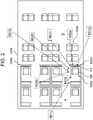
- FIG. 2 is a plan view showing details of the installation environment of the voice control device.
- FIG. 2 shows an enlarged view of the arrangement of seats in cabin A and a part of cabin B in FIG. 1 .
- a cabin 100a is divided into cabins A and B by wall 100w, and cabins A and B are provided with seat rows 103a and 103b, respectively.
- noise sources NS1a and NS1b generated from engines 102a and 102b and wind noise (noise source NS1c) at the tip portion, side surface portion, and both wings of the airframe as external noise sources.
- noise sources NS2a to NS2e from an air conditioning system or the like as noise sources inside cabin 100a.
- noise in one seat 105 disposed in cabin A is affected by noise from noise sources NS1a to NS1c caused by engines 102a and 102b (see FIG. 1 ) attached to the wings outside the window and the airflow noise and noise sources NS2a to NS2e caused by the air conditioning system, in seat 105.
- each seat 105 is surrounded by a target space for voice control (an example of a predetermined space) that is shell structure 110 as shown in FIG. 3 .
- Shell structures 110 and 110 are provided with a system for reducing noise.
- noise microphones 72 are disposed at predetermined positions of shell structures 110 and 110.
- Control sound speaker 51 is disposed in each seat 105.
- a control sound signal having a phase opposite to the noise acquired from noise microphone 72 is generated by the noise reduction control described later, and is output from control sound speaker 51.
- the noise in shell structures 110 and 110 is reduced.
- shell structure 110 On the other hand, inside shell structure 110, audio visual equipment such as a television and a radio for enjoying movies and music, a desk for businessmen, a PC connection power supply, and the like are disposed.
- Seats 105 in first class and the like are required to provide passengers (hereinafter referred to as users) with an environment in which the users can relax and concentrate on the business.
- control sound speaker 51 for viewing and listening to movies, music, and the like. However, in that case, the following problems arise.
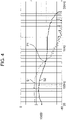
- noise signal S1 has a characteristic that the sound pressure level in the low frequency range is high and the sound pressure level in the high frequency range is low. Sound leakage occurs in the frequency band in which the sound pressure level of content voice signal S2 exceeds the sound pressure level of noise signal S1. In noise signal S1, the sound pressure level is reduced to some extent by the output of the control sound for noise reduction, but the noise in the low frequency range is large. Therefore, even if noise signal S1 is reduced by the control sound, it is considered that noise signal S1 is not lower than the sound pressure level of content voice signal S2 in the low frequency band.
- noise signal S1 is lower than the sound pressure level of content voice signal S2 in the high frequency band. Therefore, even in a noisy environment, when user U listens to the content voice without headphones or earphones, sound leakage occurs in the high frequency range of the voice. In particular, as shown in FIG. 3 , when the target spaces for voice control are disposed next to each other, sound leaks to the adjacent aisles and seats. Such sound leakage is annoying to other users U, and hinders the operation of the aircraft.
- control sound speaker 51 is a speaker suitable for outputting a control sound that reduces noise, that is, for outputting a low frequency signal. Therefore, control sound speaker 51 is not particularly suitable for the output of content voice signal S2 having large high frequency signals.
- the output of the sound source signal is divided according to the frequency band, and divided signals are output from two different speakers. This implements an environment in which user U can enjoy viewing the content in shell structure 110 without using headphones or earphones.
- the configuration and operation of the voice control device, the voice control system, and the voice control method will be described by providing the speaker for the high frequency range according to the first exemplary embodiment.
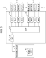
- FIG. 5 shows the basic configuration of voice control system 1.
- Voice control system 1 is disposed in the space of each seat.
- Voice control system 1 includes voice control device 10, speaker group 5, and microphones group 7.
- Voice control device 10 includes Digital Signal Processor (DSP) 11, D/A converter group 20, A/D converter group 30, and network card (NIC) 40.
- DSP 11 includes a circuit and a memory for executing voice control including noise reduction control as described later.
- Each D/A converter (an example of the voice output unit) of D/A converter group 20 is connected to each speaker.
- Each D/A converter converts the voice signal and the control sound signal generated by DSP 11 from a digital signal to an analog signal and outputs the converted signal to the speaker.
- Each A/D converter (an example of a sound collection signal input unit) of A/D converter group 30 is connected to each microphone.
- Each A/D converter converts the voice collected by the microphone from an analog signal to a digital signal and inputs the converted signal to DSP 11.
- Network card 40 (an example of a sound source signal input unit) includes a circuit or a terminal for communicating with management device 8.
- Network card 40 receives sound source data 80 of the content from management device 8.
- Speaker group 5 includes control sound speaker 51 and speaker array 52 shown in FIG. 6 .
- Control sound speaker 51 is a speaker designed to be suitable for outputting a low frequency signal. As will be described later, control sound speaker 51 amplifies and outputs the control sound signal output from noise reduction controller 17. The control sound is a voice signal generated to offset the noise. Control sound speaker 51 also amplifies and outputs the low frequency signal of the sound source signal, as will be described later.
- Speaker array 52 is a speaker suitable for high-pitched sound output, and includes a plurality of speakers disposed in a row. As will be described later, speaker array 52 amplifies and outputs a high frequency sound signal such that the sound power is concentrated in the vicinity of a control point on the head of user U, by a wave field synthesis technique.
- microphone group 7 include content voice detection microphone 71, noise microphone 72, and error microphone 73.
- Content voice detection microphone 71 is a microphone for detecting a content reproduction signal output in the space of shell structure 110, and collects sounds around the microphone.
- the voice signal collected by content voice detection microphone 71 is input to frequency determination unit 12 of DSP 11 via corresponding A/D converter 31.
- Noise microphone 72 is a microphone for detecting the sound emitted from the noise source, and collects the sound around the microphone.
- the voice signal collected by noise microphone 72 is input to noise reduction controller 17 of DSP 11 via corresponding A/D converter 32.
- Error microphone 73 is a microphone for detecting residual sound (error sound) as a result of overlapping the sound emitted from the noise source and the control sound emitted from control sound speaker 51. Error microphone 73 is disposed near the head of user U, which is a control point. A plurality of content voice detection microphones 71, a plurality of noise microphones 72, and a plurality of error microphones 73 may be provided.
- the voice controller system may be connected to management device 8 of aircraft 100.
- Management device 8 includes a processor including a control circuit such as a CPU and a memory, and includes a computer that operates according to a predetermined program.
- Management device 8 stores sound source data 80 of the content.
- Sound source data 80 of the content includes sound source data of the content that can be viewed by user U as desired, such as a voice of music, a movie, a television, a radio, or the like.
- DSP 11 executes the functions of frequency determination unit 12, band controller 13, sound image controller 15, and noise reduction controller 17 shown in FIG. 6 .
- Frequency determination unit 12 determines the cutoff frequency based on the content reproduction signal and the noise signal. Specifically, frequency determination unit 12 acquires the content reproduction signal collected by content voice detection microphone 71. The sound collection signal collected by content voice detection microphone 71 also includes a noise signal. The frequency determination unit acquires, for example, the frequency characteristics of the content reproduction signal as shown in FIG. 4 , by removing the noise signal in shell structure 110, from the sound collection signal. The noise signal in shell structure 110 may be measured in advance and stored in a memory, when the content reproduction signal is not output from the speaker. The noise signal has frequency characteristics similar to those of noise signal S1 shown in FIG. 4 , that is, the lower the frequency, the higher the sound pressure level.
- Frequency determination unit 12 determines the cutoff frequency at which the sound pressure level of the content reproduction signal becomes equal to or higher than the sound pressure level of the noise signal, from the frequency characteristics of the content reproduction signal and the frequency characteristics of the noise signal acquired from content voice detection microphone 71.
- the cutoff frequency is, for example, the frequency indicated by PI shown in FIG. 4 .
- the cutoff frequency changes according to changes in the sound pressure level and frequency characteristics of the content reproduction signal collected by content voice detection microphone 71. Therefore, frequency determination unit 12 monitors such a change, and changes the cutoff frequency when the change occurs.
- Frequency determination unit 12 may make a determination according to the number of speakers in speaker array 52, at least in the initial state. Further, content voice detection microphone 71 may be disposed in the vicinity of control sound speaker 51, and determine the cutoff frequency according to the frequency band of the low frequency signal output from control sound speaker 51.
- Band controller 13 acquires the sound source signal of the content, from sound source data 80.
- Band controller 13 includes filter circuits such as a Low Pass Filter (LPF), a High Pass Filter (HPF), and a Band Pass Filter (BPF), and divides a sound source signal into two band signals, according to the cutoff frequency determined by frequency determination unit 12. Specifically, band controller 13 acquires a high frequency signal in a frequency band equal to or higher than the cutoff frequency and a low frequency signal in a frequency band equal to or lower than the cutoff frequency, from the sound source signal.
- the high frequency signal is input to sound image controller 15.
- the low frequency signal is output to control sound speaker 51 together with the control sound signal output from noise reduction controller 17.
- the frequency band equal to or higher than the cutoff frequency includes both the case where the cutoff frequency is included and the case where the cutoff frequency is not included.
- the frequency band equal to or lower than the cutoff frequency includes both the case where the cutoff frequency is included and the case where the cutoff frequency is not included.
- Sound image controller 15 performs a wave field synthesis process for controlling at least one of the phase and the sound pressure level of the acquired high frequency signal such that the sound image is localized at the control point near the head of user U.
- sound image controller 15 includes a plurality of wave field synthesis filters 15a, 15b, ..., which are digital filters.
- Wave field synthesis filters 15a, 15b, ... correspond to speakers 52a, 52b, ... of speaker array 52, respectively, and form a plurality of channels (for example, 16 channels).
- filter coefficients are set according to the distance between the control point near the head of user U in shell structure 110 and speaker array 52.
- the output from speaker array 52 is controlled to concentrate the power of the high frequency sound signal output in the vicinity of the designated control point.
- the filter coefficient By convolving the filter coefficient, the output from speaker array 52 is controlled to concentrate the power of the high frequency sound signal output in the vicinity of the designated control point.
- user U can sufficiently hear the voice signals from speakers 52a, 52b, ... of speaker array 52.
- Noise reduction controller 17 generates a control sound signal for reducing the noise signal, and outputs the control sound signal to control sound speaker 51 via D/A converter 21. As shown in FIG. 8 , noise reduction controller 17 includes adaptive filter 171, and coefficient update unit 172.
- Adaptive filter 171 is a circuit that generates a control sound signal that reduces noise.
- Adaptive filter 171 is, for example, a Finite Impulse Response (FIR) filter that is composed of multi-stage taps and can freely set the filter coefficient of each tap.
- FIR Finite Impulse Response
- Coefficient update unit 172 is implemented by a predetermined algorithm (for example, Least Mean Square (LMS)) executed by the processor.
- Coefficient update unit 172 acquires the error sound from error microphone 73 in addition to the noise input from noise microphone 72.
- Coefficient update unit 172 updates the transfer function and adjusts each filter coefficient of adaptive filter 171 such that this error sound is minimized.
- a control sound signal having a phase opposite to the noise from the noise source is generated at the control point near the installation position of error microphone 73.
- the generated control sound signal is output to control sound speaker 51 via D/A converter together with the low frequency signal of the sound source signal of the content described above.
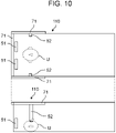
- FIGS. 9 and 10 show an arrangement example of the microphone and the speaker according to the first exemplary embodiment.
- the upper view is a plan view
- the lower view is an elevation view corresponding to the plan view.
- User U is lying in shell structure 110.
- control sound speaker 51 is disposed at a control point near the head of user U. Since control sound speaker 51 outputs a control sound that reduces noise, it is desirable that control sound speaker 51 is disposed near the control point.
- speaker array 52 is disposed at a position away from the control point (for example, the wall in front of the foot side of user U). As described above, the sound image of the voice signal output from speaker array 52 is localized in the vicinity of the control point, by the wave field synthesis process by sound image controller 15. Therefore, even if the output of each speaker of speaker array 52 is small, it is possible to provide user U with a sufficiently audible volume. Further, since speaker array 52 can reduce the sound output, the risk of sound leakage can be reduced.
- Content voice detection microphone 71 is disposed above and close to the control point in shell structure 110.
- speaker array 52 is not limited to the arrangement shown in FIG. 9 .
- speaker array 52 may be disposed near the control point.
- the longitudinal direction of speaker array 52 is disposed vertically with respect to the floor surface of seat shell structure 110.
- Such an arrangement has an effect of facilitating the wave field synthesis of the voice signal output from each speaker configuring speaker array 52 such that the sound emitted by speaker array 52 has a directivity so as to be prevented from leaking to the outside of the shell beyond the edge of shell structure 110.
- FIG. 9 shows an example in which speaker array 52 is disposed such that longitudinal direction is perpendicular to the floor surface, it is not always necessary to arrange speaker array 52 strictly perpendicular to the floor surface. The same effect can be obtained even if the longitudinal direction of speaker array 52 is deviated from the vertical direction and slanted.
- speaker array 52 may be disposed such that the longitudinal direction of speaker array 52 is perpendicular to the edge direction of shell structure 110. Further, the intervals between the individual speakers of speaker array 52 may be irregular or uniform.
- the speakers may be disposed side by side along the surface of the curved structure such that the distance between the individual speakers is substantially uniform.
- content voice detection microphone 71 is provided independently, but it is not always necessary to provide a dedicated microphone for detecting the content reproduction signal. Even if each noise microphone and error microphone installed in shell structure 110 share functions and are used as content voice detection microphone 71, a certain effect can be obtained.
- voice control device 10 The operation of voice control device 10 will be mainly described with reference to FIG. 11 .
- User U requests the distribution of the sound source data by operating the remote controller or the touch panel installed in seat 105.
- the sound source signal is received (S101).
- the sound collection signal collected by content voice detection microphone 71 is received (S102).
- the noise reduction control by noise reduction controller 17 is executed in parallel.
- Frequency determination unit 12 acquires a content reproduction signal from the sound collection signal collected by content voice detection microphone 71, and determines the cutoff frequency, based on the content reproduction signal and the noise signal (S103).
- Band controller 13 acquires a high frequency signal in a frequency band equal to or higher than the cutoff frequency and a low frequency signal in a frequency band equal to or lower than the cutoff frequency, from the sound source signal (S104).
- the high frequency signal is subjected to a wave field synthesis process by sound image controller 15 (S105).
- the high frequency signal subjected to the wave field synthesis process is output to speaker array 52 (S106).
- the low frequency signal is output to control sound speaker 51 together with the control sound signal generated by noise reduction controller 17 (S107).
- frequency determination unit 12 When an end condition such as stop of the transmission of the sound source signal occurs, the process ends (S108). On the other hand, when the end condition does not occur, frequency determination unit 12 continues to monitor changes in the sound pressure level and frequency characteristics of the content reproduction signal collected by content voice detection microphone 71. Frequency determination unit 12 repeats the operations of steps S102 to S108, according to the change.
- the sound pressure level of the content reproduction signal can be controlled so as not to exceed the sound pressure level of the noise signal. Therefore, user U can enjoy the sound without headphones or earphones, while preventing the sound from leaking from shell structure 110 to the outside.
- FIG. 12 shows a configuration of voice control system 1 according to a modification example of the first exemplary embodiment.
- tweeter 53 is provided instead of speaker array 52, and sound image controller 15 is not provided. Tweeter 53 is a speaker suitable for high-pitched sound output.
- the high frequency signal divided by band controller 13 is output to tweeter 53 via D/A converter 22.
- FIG. 13 which is a diagram similar to FIGS. 9 and 10 , tweeter 53 is disposed on the left and right in the vicinity of the control point.
- user U can sufficiently hear the output sound even if the output is small, and can reduce the risk of sound leakage.
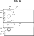
- tweeter 53 is disposed below shell structure 110 in accordance with the state in which user U is lying in shell structure 110. On the other hand, when it is assumed that user U hears the sound in a sitting posture, tweeter 53 may be disposed above shell structure 110 as shown in FIG. 14 .
- the cutoff frequency is determined based on the content reproduction signal output from the speaker and the noise signal
- the sound source signal of the content is divided into a high frequency signal in a frequency band equal to or higher than the cutoff frequency and a low frequency signal in a frequency band equal to or lower than the cutoff frequency
- the low frequency signal is output to control sound speaker 51 that outputs a control sound signal for noise reduction
- the high frequency signal is output to speaker array 52.
- the high frequency signal that causes sound leakage to the outside of shell structure 110 is subjected to the wave field synthesis process and output from speaker array 52.
- the wave field synthesis process and output from speaker array 52 it is possible to prevent sound leakage while providing a sound having a sufficient sound pressure level with a small output level to the control point near the head of user U, for the high frequency signal.
- control sound speaker 51 that is provided for noise reduction and is suitable for the low frequency signal is used.
- the cutoff frequency is changed according to changes in the content and noise signal, and the voice can be controlled such that the sound pressure level of the high frequency signal does not exceed the sound pressure level of the noise signal. Therefore, sound leakage can be prevented more reliably.
- the noise reduction operation can be executed in parallel, the sound of the content can be reproduced while reducing the noise.
- Voice control system 2 according to a second exemplary embodiment will be described with reference to FIG. 15 .
- the same configurations and functions as those in the first exemplary embodiment are designated by the same reference numerals, and the description thereof will be omitted.
- Voice control system 2 according to the second exemplary embodiment is different from voice control system 1 according to the first exemplary embodiment in that it does not have noise reduction controller 17.
- the low frequency signal of the sound source signal acquired by band controller 13 is output to low frequency speaker 54 via the D/A converter.
- Low frequency speaker 54 may be a speaker having the same configuration and function as control sound speaker 51.
- voice control system 2 has the same effect as that of the first exemplary embodiment except for the noise reduction effect even when the noise reduction process is not executed. That is, while preventing sound leakage, it is possible to complement the sounds in different frequency bands with each other by low frequency speaker 54 and speaker array 52, and it becomes possible to reproduce the sound of content in a wide band near the head of user U. User U can view the content without using headphones or earphones.
- tweeter 53 ( FIG. 12 ) may be provided instead of speaker array 52, and sound image controller 15 may not be provided, as in the first exemplary embodiment.
- a voice control system 3 according to a third exemplary embodiment will be described with reference to FIG. 17 .
- the same configurations and functions as those of the first exemplary embodiment and the second exemplary embodiment are designated by the same reference numerals, and the description thereof will be omitted.
- Voice control system 3 according to the third exemplary embodiment is different from voice control system 1 according to the first exemplary embodiment in that it does not have noise reduction controller 17 and has seat management unit 14.
- the low frequency signal of the sound source signal acquired by band controller 13 is output to low frequency speaker 54 via the D/A converter.
- frequency determination unit 12 determines the cutoff frequency, based on the content reproduction signal and the noise signal, but in the third exemplary embodiment, a different method is used to determine the cutoff frequency.
- Frequency determination unit 12 stores a cutoff frequency that is determined in advance so as to enable wide band reproduction by complementing each other, based on the reproduction frequency band of speaker array 52 and the reproduction frequency band of low frequency speaker 54. For these reproduction frequency bands, it is conceivable to use the nominal specifications of each speaker, or actual measurement values and simulation values in the actual usage environment of the system.
- Frequency determination unit 12 determines the cutoff frequency by using the cutoff frequency stored in advance. Frequency determination unit 12 may use the predetermined cutoff frequency in a fixed manner, or may determine the cutoff frequency according to the characteristics of the content and the settings of the system at the time of content reproduction.
- Band controller 13 adjusts the sound pressure level of the high frequency signal output from speaker array 52 and the sound pressure level of the low frequency signal output from low frequency speaker 54, so that the high frequency range and the low frequency range that user U views can be balanced.
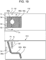
- the sound pressure level of the low frequency signal and the sound pressure level of the high frequency signal are adjusted according to the seat information such as the bed state, the reclining state, and the like acquired by seat management unit 14, so that it is possible to construct a good sound environment according to the head position of user U in the bed state shown in FIG. 18 and the head position of user U in the reclining state shown in FIG. 19 .
- Low frequency speaker 54 may be a speaker having the same configuration and function as control sound speaker 51 described in the first exemplary embodiment.
- FIGS. 18 and 19 show an arrangement example of the microphone and the speaker according to the third exemplary embodiment.
- the upper view is a plan view
- the lower view is an elevation view corresponding to the plan view.
- User U in FIG. 18 is lying in shell structure 110.
- Back cushion 90a, seat cushion 90b, and leg cushion 90c are lined up almost flat to be in a bed state.
- User U in FIG. 19 is sitting in a chair in shell structure 110.
- Back cushion 90a, seat cushion 90b, and leg cushion 90c are disposed at different angles to be in a reclining state.
- User U operates the positions and angles of back cushion 90a, seat cushion 90b, and leg cushion 90c by using the seat operation panel provided on the seat wall, the armrest, and the like, so that the seat state such as the bed state of FIG. 18 , the reclining state of FIG. 19 , and the intermediate state thereof can be changed.
- low frequency speaker 54 is disposed near the head of user U on shell structure 110.
- low frequency speaker 54 is not disposed near the head of user U.
- speaker array 52 is disposed near the head of user U on shell structure 110.
- the sound image of the voice signal output from speaker array 52 is localized in the vicinity of the head of user U, by the wave field synthesis process by sound image controller 15. Therefore, even if the output of each speaker of speaker array 52 is small, it is possible to provide user U with a sufficiently audible volume.
- speaker array 52 can reduce the sound output in locations other than the location where the sound image is localized by the wave field synthesis process, the risk of sound leakage to the outside of shell structure 110 can be reduced.
- 52a, 52b, 52c, 52d, and 52e in FIG. 18 show the arrangement of individual speakers located inside speaker array 52. Five speakers 52a to 52e are shown for convenience, but the number of speakers may be other than 5. Speakers 52a to 52e are disposed vertically with respect to the floor surface of shell structure 110. Such an arrangement has an effect of facilitating the wave field synthesis of the voice signal output from each speaker configuring speaker array 52 such that the sound emitted by speaker array 52 has a directivity so as to be prevented from leaking to the outside of the shell beyond the edge of shell structure 110.
- the longitudinal direction of speaker array 52 is disposed in the vertical direction, the longitudinal direction does not necessarily need to be exactly aligned vertically.
- the longitudinal direction of speaker array 52 may be deviated from the vertical direction and slanted, or when the direction of the edge of shell structure 110 is, for example, the horizontal direction or the vertical direction, speaker array 52 may be disposed such that the longitudinal direction of speaker array 52 is perpendicular to the edge direction of shell structure 110. Further, the intervals between the individual speakers of speaker array 52 may be irregular or uniform.
- the speakers may be disposed side by side along the surface of the curved structure such that the distance between the individual speakers is substantially uniform.
- content voice detection microphone 71 may be provided above the head of user U or the like to detect the content voice leaking to the outside of the shell, and the sound pressure level of the voice output from speaker array 52 and low frequency speaker 54 may be adjusted such that the voice is equal to or less than the threshold value.
- voice control system 3 has the same effect as that of the first exemplary embodiment except for the noise reduction effect even when the noise reduction process is not executed. That is, while preventing sound leakage, it is possible to complement the sounds in different frequency bands with each other by low frequency speaker 54 and speaker array 52, and it becomes possible to reproduce the sound of content in a wide band near the head of user U. User U can view the content without using headphones or earphones.
- tweeter 53 ( FIG. 12 ) may be provided instead of speaker array 52, and sound image controller 15 may not be provided, as in the first exemplary embodiment.
- the above-described exemplary embodiments have been described as examples of the technique disclosed in the present application.
- the technique in the present disclosure is not limited to these exemplary embodiments, and can be applied to exemplary embodiments in which changes, replacements, additions, omissions, and the like are made as appropriate. It is also possible to combine the components described in the above exemplary embodiments to form new exemplary embodiments.
Landscapes
- Engineering & Computer Science (AREA)
- Physics & Mathematics (AREA)
- Acoustics & Sound (AREA)
- Health & Medical Sciences (AREA)
- Multimedia (AREA)
- Audiology, Speech & Language Pathology (AREA)
- General Health & Medical Sciences (AREA)
- Signal Processing (AREA)
- Computational Linguistics (AREA)
- Human Computer Interaction (AREA)
- Otolaryngology (AREA)
- Quality & Reliability (AREA)
- Soundproofing, Sound Blocking, And Sound Damping (AREA)
- Circuit For Audible Band Transducer (AREA)
- Obtaining Desirable Characteristics In Audible-Bandwidth Transducers (AREA)
Applications Claiming Priority (2)
| Application Number | Priority Date | Filing Date | Title |
|---|---|---|---|
| JP2019131955 | 2019-07-17 | ||
| PCT/JP2020/027376 WO2021010397A1 (fr) | 2019-07-17 | 2020-07-14 | Dispositif et système de commande vocale |
Publications (3)
| Publication Number | Publication Date |
|---|---|
| EP4002877A1 true EP4002877A1 (fr) | 2022-05-25 |
| EP4002877A4 EP4002877A4 (fr) | 2022-12-28 |
| EP4002877B1 EP4002877B1 (fr) | 2025-04-30 |
Family
ID=74210423
Family Applications (1)
| Application Number | Title | Priority Date | Filing Date |
|---|---|---|---|
| EP20841254.4A Active EP4002877B1 (fr) | 2019-07-17 | 2020-07-14 | Dispositif et système de commande vocale |
Country Status (4)
| Country | Link |
|---|---|
| US (1) | US12039992B2 (fr) |
| EP (1) | EP4002877B1 (fr) |
| JP (1) | JP7316619B2 (fr) |
| WO (2) | WO2021010006A1 (fr) |
Families Citing this family (5)
| Publication number | Priority date | Publication date | Assignee | Title |
|---|---|---|---|---|
| US11856363B2 (en) | 2022-02-28 | 2023-12-26 | Panasonic Intellectual Property Management Co., Ltd. | Acoustic apparatus |
| US11843927B2 (en) * | 2022-02-28 | 2023-12-12 | Panasonic Intellectual Property Management Co., Ltd. | Acoustic control system |
| JPWO2024070165A1 (fr) * | 2022-09-26 | 2024-04-04 | ||
| JPWO2024161995A1 (fr) * | 2023-02-02 | 2024-08-08 | ||
| WO2025094624A1 (fr) * | 2023-10-31 | 2025-05-08 | パナソニックIpマネジメント株式会社 | Système de commande sonore |
Family Cites Families (19)
| Publication number | Priority date | Publication date | Assignee | Title |
|---|---|---|---|---|
| JPS5015611B1 (fr) | 1970-09-29 | 1975-06-06 | ||
| JP2000307385A (ja) * | 1999-04-19 | 2000-11-02 | Alpine Electronics Inc | 周波数分割回路 |
| JP4735920B2 (ja) * | 2001-09-18 | 2011-07-27 | ソニー株式会社 | 音響処理装置 |
| JP2004056262A (ja) | 2002-07-17 | 2004-02-19 | Sony Corp | 音響システム |
| US20080025518A1 (en) | 2005-01-24 | 2008-01-31 | Ko Mizuno | Sound Image Localization Control Apparatus |
| JP4946148B2 (ja) | 2006-04-19 | 2012-06-06 | ソニー株式会社 | 音声信号処理装置、音声信号処理方法及び音声信号処理プログラム |
| JP4722878B2 (ja) | 2007-04-19 | 2011-07-13 | ソニー株式会社 | ノイズ低減装置および音響再生装置 |
| JP2009065452A (ja) | 2007-09-06 | 2009-03-26 | Panasonic Corp | 音像定位制御装置、音像定位制御方法、プログラム、および集積回路 |
| JP2009143495A (ja) | 2007-12-17 | 2009-07-02 | Fujitsu Ten Ltd | 音響制御装置 |
| JP2010083267A (ja) | 2008-09-30 | 2010-04-15 | Panasonic Corp | 騒音低減装置 |
| JP5821307B2 (ja) | 2011-06-13 | 2015-11-24 | ソニー株式会社 | 情報処理装置、情報処理方法及びプログラム |
| JP2013142735A (ja) * | 2012-01-10 | 2013-07-22 | Audio Technica Corp | ノイズキャンセルヘッドホン |
| US9008330B2 (en) * | 2012-09-28 | 2015-04-14 | Sonos, Inc. | Crossover frequency adjustments for audio speakers |
| JP5743003B2 (ja) | 2014-05-09 | 2015-07-01 | ソニー株式会社 | 波面合成信号変換装置および波面合成信号変換方法 |
| US9432761B2 (en) * | 2014-10-08 | 2016-08-30 | Nxp B.V. | Signal processor |
| JP2016100613A (ja) * | 2014-11-18 | 2016-05-30 | ソニー株式会社 | 信号処理装置、信号処理方法、およびプログラム |
| JP6718748B2 (ja) | 2015-08-31 | 2020-07-08 | パナソニック インテレクチュアル プロパティ コーポレーション オブ アメリカPanasonic Intellectual Property Corporation of America | エリア再生システム及びエリア再生方法 |
| US9754575B2 (en) | 2015-08-31 | 2017-09-05 | Panasonic Intellectual Property Corporation Of America | Area-sound reproduction system and area-sound reproduction method |
| EP3425925A1 (fr) | 2017-07-07 | 2019-01-09 | Harman Becker Automotive Systems GmbH | Système de pièces pour haut-parleurs |
-
2020
- 2020-05-13 WO PCT/JP2020/019149 patent/WO2021010006A1/fr not_active Ceased
- 2020-07-14 US US17/627,398 patent/US12039992B2/en active Active
- 2020-07-14 JP JP2021533079A patent/JP7316619B2/ja active Active
- 2020-07-14 EP EP20841254.4A patent/EP4002877B1/fr active Active
- 2020-07-14 WO PCT/JP2020/027376 patent/WO2021010397A1/fr not_active Ceased
Also Published As
| Publication number | Publication date |
|---|---|
| US12039992B2 (en) | 2024-07-16 |
| WO2021010397A1 (fr) | 2021-01-21 |
| EP4002877A4 (fr) | 2022-12-28 |
| EP4002877B1 (fr) | 2025-04-30 |
| US20220262385A1 (en) | 2022-08-18 |
| JP7316619B2 (ja) | 2023-07-28 |
| JPWO2021010397A1 (fr) | 2021-01-21 |
| WO2021010006A1 (fr) | 2021-01-21 |
Similar Documents
| Publication | Publication Date | Title |
|---|---|---|
| EP4002877B1 (fr) | Dispositif et système de commande vocale | |
| US8565442B2 (en) | Noise reduction device | |
| JP6965216B2 (ja) | Anrヘッドホンで周囲の自然さを提供すること | |
| CN101292567B (zh) | 噪声控制装置 | |
| US9792892B2 (en) | Noise cancellation system | |
| US9183825B2 (en) | Noise reduction apparatus | |
| EP2551845B1 (fr) | Reproduction de sons réduisant le bruit | |
| EP3627492A1 (fr) | Dispositif de réduction du bruit, système de réduction du bruit et procédé de commande du champ sonore | |
| JP5327049B2 (ja) | 騒音低減装置 | |
| US9153223B2 (en) | Noise reduction device | |
| US10157605B2 (en) | Noise reduction device | |
| US11843927B2 (en) | Acoustic control system | |
| US12243507B2 (en) | Gain adjustment in ANR system with multiple feedforward microphones | |
| EP2629289B1 (fr) | Système de contrôle actif de bruit avec rétroaction et une voie secondaire longue | |
| US20250087200A1 (en) | Sound system | |
| US12513456B2 (en) | Sound system | |
| Goose et al. | Paz: In-vehicle personalized audio zones | |
| EP3528241A1 (fr) | Dispositif de réduction du bruit, système de réduction du bruit et procédé de commande de réduction du bruit | |
| EP4234405A1 (fr) | Dispositif audio | |
| US20250227412A1 (en) | Acoustic device, playback method, and non-transitory computer readable storage medium | |
| US20240137694A1 (en) | Sound system | |
| WO2025094624A1 (fr) | Système de commande sonore |
Legal Events
| Date | Code | Title | Description |
|---|---|---|---|
| STAA | Information on the status of an ep patent application or granted ep patent |
Free format text: STATUS: THE INTERNATIONAL PUBLICATION HAS BEEN MADE |
|
| PUAI | Public reference made under article 153(3) epc to a published international application that has entered the european phase |
Free format text: ORIGINAL CODE: 0009012 |
|
| STAA | Information on the status of an ep patent application or granted ep patent |
Free format text: STATUS: REQUEST FOR EXAMINATION WAS MADE |
|
| 17P | Request for examination filed |
Effective date: 20220114 |
|
| AK | Designated contracting states |
Kind code of ref document: A1 Designated state(s): AL AT BE BG CH CY CZ DE DK EE ES FI FR GB GR HR HU IE IS IT LI LT LU LV MC MK MT NL NO PL PT RO RS SE SI SK SM TR |
|
| RIC1 | Information provided on ipc code assigned before grant |
Ipc: G10K 11/178 20060101ALI20220824BHEP Ipc: H04R 3/14 20060101AFI20220824BHEP |
|
| DAV | Request for validation of the european patent (deleted) | ||
| DAX | Request for extension of the european patent (deleted) | ||
| REG | Reference to a national code |
Ref country code: DE Ref legal event code: R079 Free format text: PREVIOUS MAIN CLASS: H04R0001400000 Ipc: H04R0003140000 Ref country code: DE Ref legal event code: R079 Ref document number: 602020050557 Country of ref document: DE Free format text: PREVIOUS MAIN CLASS: H04R0001400000 Ipc: H04R0003140000 |
|
| A4 | Supplementary search report drawn up and despatched |
Effective date: 20221130 |
|
| RIC1 | Information provided on ipc code assigned before grant |
Ipc: G10K 11/178 20060101ALI20221124BHEP Ipc: H04R 3/14 20060101AFI20221124BHEP |
|
| GRAP | Despatch of communication of intention to grant a patent |
Free format text: ORIGINAL CODE: EPIDOSNIGR1 |
|
| STAA | Information on the status of an ep patent application or granted ep patent |
Free format text: STATUS: GRANT OF PATENT IS INTENDED |
|
| INTG | Intention to grant announced |
Effective date: 20241213 |
|
| RIN1 | Information on inventor provided before grant (corrected) |
Inventor name: KUBOTA, KENICHI Inventor name: YAMAGUCHI, TAKAHIRO Inventor name: ABE, SATOSHI Inventor name: ARAKI, JUNJI |
|
| GRAS | Grant fee paid |
Free format text: ORIGINAL CODE: EPIDOSNIGR3 |
|
| GRAA | (expected) grant |
Free format text: ORIGINAL CODE: 0009210 |
|
| STAA | Information on the status of an ep patent application or granted ep patent |
Free format text: STATUS: THE PATENT HAS BEEN GRANTED |
|
| AK | Designated contracting states |
Kind code of ref document: B1 Designated state(s): AL AT BE BG CH CY CZ DE DK EE ES FI FR GB GR HR HU IE IS IT LI LT LU LV MC MK MT NL NO PL PT RO RS SE SI SK SM TR |
|
| REG | Reference to a national code |
Ref country code: CH Ref legal event code: EP Ref country code: GB Ref legal event code: FG4D |
|
| REG | Reference to a national code |
Ref country code: DE Ref legal event code: R096 Ref document number: 602020050557 Country of ref document: DE |
|
| REG | Reference to a national code |
Ref country code: IE Ref legal event code: FG4D |
|
| REG | Reference to a national code |
Ref country code: NL Ref legal event code: MP Effective date: 20250430 |
|
| REG | Reference to a national code |
Ref country code: AT Ref legal event code: MK05 Ref document number: 1791209 Country of ref document: AT Kind code of ref document: T Effective date: 20250430 |
|
| PG25 | Lapsed in a contracting state [announced via postgrant information from national office to epo] |
Ref country code: ES Free format text: LAPSE BECAUSE OF FAILURE TO SUBMIT A TRANSLATION OF THE DESCRIPTION OR TO PAY THE FEE WITHIN THE PRESCRIBED TIME-LIMIT Effective date: 20250430 Ref country code: FI Free format text: LAPSE BECAUSE OF FAILURE TO SUBMIT A TRANSLATION OF THE DESCRIPTION OR TO PAY THE FEE WITHIN THE PRESCRIBED TIME-LIMIT Effective date: 20250430 Ref country code: PT Free format text: LAPSE BECAUSE OF FAILURE TO SUBMIT A TRANSLATION OF THE DESCRIPTION OR TO PAY THE FEE WITHIN THE PRESCRIBED TIME-LIMIT Effective date: 20250901 |
|
| PGFP | Annual fee paid to national office [announced via postgrant information from national office to epo] |
Ref country code: DE Payment date: 20250722 Year of fee payment: 6 |
|
| REG | Reference to a national code |
Ref country code: LT Ref legal event code: MG9D |
|
| PG25 | Lapsed in a contracting state [announced via postgrant information from national office to epo] |
Ref country code: GR Free format text: LAPSE BECAUSE OF FAILURE TO SUBMIT A TRANSLATION OF THE DESCRIPTION OR TO PAY THE FEE WITHIN THE PRESCRIBED TIME-LIMIT Effective date: 20250731 Ref country code: NO Free format text: LAPSE BECAUSE OF FAILURE TO SUBMIT A TRANSLATION OF THE DESCRIPTION OR TO PAY THE FEE WITHIN THE PRESCRIBED TIME-LIMIT Effective date: 20250730 |
|
| PG25 | Lapsed in a contracting state [announced via postgrant information from national office to epo] |
Ref country code: NL Free format text: LAPSE BECAUSE OF FAILURE TO SUBMIT A TRANSLATION OF THE DESCRIPTION OR TO PAY THE FEE WITHIN THE PRESCRIBED TIME-LIMIT Effective date: 20250430 Ref country code: PL Free format text: LAPSE BECAUSE OF FAILURE TO SUBMIT A TRANSLATION OF THE DESCRIPTION OR TO PAY THE FEE WITHIN THE PRESCRIBED TIME-LIMIT Effective date: 20250430 |
|
| PG25 | Lapsed in a contracting state [announced via postgrant information from national office to epo] |
Ref country code: BG Free format text: LAPSE BECAUSE OF FAILURE TO SUBMIT A TRANSLATION OF THE DESCRIPTION OR TO PAY THE FEE WITHIN THE PRESCRIBED TIME-LIMIT Effective date: 20250430 |
|
| PG25 | Lapsed in a contracting state [announced via postgrant information from national office to epo] |
Ref country code: HR Free format text: LAPSE BECAUSE OF FAILURE TO SUBMIT A TRANSLATION OF THE DESCRIPTION OR TO PAY THE FEE WITHIN THE PRESCRIBED TIME-LIMIT Effective date: 20250430 |
|
| PG25 | Lapsed in a contracting state [announced via postgrant information from national office to epo] |
Ref country code: AT Free format text: LAPSE BECAUSE OF FAILURE TO SUBMIT A TRANSLATION OF THE DESCRIPTION OR TO PAY THE FEE WITHIN THE PRESCRIBED TIME-LIMIT Effective date: 20250430 |
|
| PG25 | Lapsed in a contracting state [announced via postgrant information from national office to epo] |
Ref country code: RS Free format text: LAPSE BECAUSE OF FAILURE TO SUBMIT A TRANSLATION OF THE DESCRIPTION OR TO PAY THE FEE WITHIN THE PRESCRIBED TIME-LIMIT Effective date: 20250731 |
|
| PG25 | Lapsed in a contracting state [announced via postgrant information from national office to epo] |
Ref country code: IS Free format text: LAPSE BECAUSE OF FAILURE TO SUBMIT A TRANSLATION OF THE DESCRIPTION OR TO PAY THE FEE WITHIN THE PRESCRIBED TIME-LIMIT Effective date: 20250830 |
|
| PG25 | Lapsed in a contracting state [announced via postgrant information from national office to epo] |
Ref country code: LV Free format text: LAPSE BECAUSE OF FAILURE TO SUBMIT A TRANSLATION OF THE DESCRIPTION OR TO PAY THE FEE WITHIN THE PRESCRIBED TIME-LIMIT Effective date: 20250430 |
|
| PG25 | Lapsed in a contracting state [announced via postgrant information from national office to epo] |
Ref country code: SM Free format text: LAPSE BECAUSE OF FAILURE TO SUBMIT A TRANSLATION OF THE DESCRIPTION OR TO PAY THE FEE WITHIN THE PRESCRIBED TIME-LIMIT Effective date: 20250430 Ref country code: DK Free format text: LAPSE BECAUSE OF FAILURE TO SUBMIT A TRANSLATION OF THE DESCRIPTION OR TO PAY THE FEE WITHIN THE PRESCRIBED TIME-LIMIT Effective date: 20250430 |
|
| PG25 | Lapsed in a contracting state [announced via postgrant information from national office to epo] |
Ref country code: CZ Free format text: LAPSE BECAUSE OF FAILURE TO SUBMIT A TRANSLATION OF THE DESCRIPTION OR TO PAY THE FEE WITHIN THE PRESCRIBED TIME-LIMIT Effective date: 20250430 |
|
| PG25 | Lapsed in a contracting state [announced via postgrant information from national office to epo] |
Ref country code: EE Free format text: LAPSE BECAUSE OF FAILURE TO SUBMIT A TRANSLATION OF THE DESCRIPTION OR TO PAY THE FEE WITHIN THE PRESCRIBED TIME-LIMIT Effective date: 20250430 |
|
| PG25 | Lapsed in a contracting state [announced via postgrant information from national office to epo] |
Ref country code: RO Free format text: LAPSE BECAUSE OF FAILURE TO SUBMIT A TRANSLATION OF THE DESCRIPTION OR TO PAY THE FEE WITHIN THE PRESCRIBED TIME-LIMIT Effective date: 20250430 Ref country code: SK Free format text: LAPSE BECAUSE OF FAILURE TO SUBMIT A TRANSLATION OF THE DESCRIPTION OR TO PAY THE FEE WITHIN THE PRESCRIBED TIME-LIMIT Effective date: 20250430 |
|
| PG25 | Lapsed in a contracting state [announced via postgrant information from national office to epo] |
Ref country code: IT Free format text: LAPSE BECAUSE OF FAILURE TO SUBMIT A TRANSLATION OF THE DESCRIPTION OR TO PAY THE FEE WITHIN THE PRESCRIBED TIME-LIMIT Effective date: 20250430 |
|
| REG | Reference to a national code |
Ref country code: DE Ref legal event code: R097 Ref document number: 602020050557 Country of ref document: DE |
|
| REG | Reference to a national code |
Ref country code: CH Ref legal event code: H13 Free format text: ST27 STATUS EVENT CODE: U-0-0-H10-H13 (AS PROVIDED BY THE NATIONAL OFFICE) Effective date: 20260224 |
|
| PLBE | No opposition filed within time limit |
Free format text: ORIGINAL CODE: 0009261 |
|
| STAA | Information on the status of an ep patent application or granted ep patent |
Free format text: STATUS: NO OPPOSITION FILED WITHIN TIME LIMIT |
|
| REG | Reference to a national code |
Ref country code: CH Ref legal event code: L10 Free format text: ST27 STATUS EVENT CODE: U-0-0-L10-L00 (AS PROVIDED BY THE NATIONAL OFFICE) Effective date: 20260311 |
|
| PG25 | Lapsed in a contracting state [announced via postgrant information from national office to epo] |
Ref country code: LU Free format text: LAPSE BECAUSE OF NON-PAYMENT OF DUE FEES Effective date: 20250714 |
|
| GBPC | Gb: european patent ceased through non-payment of renewal fee |
Effective date: 20250730 |