EP4002919A1 - Verfahren und vorrichtung zur durchführung einer übergabe in einem drahtloskommunikationssystem - Google Patents
Verfahren und vorrichtung zur durchführung einer übergabe in einem drahtloskommunikationssystem Download PDFInfo
- Publication number
- EP4002919A1 EP4002919A1 EP20886137.7A EP20886137A EP4002919A1 EP 4002919 A1 EP4002919 A1 EP 4002919A1 EP 20886137 A EP20886137 A EP 20886137A EP 4002919 A1 EP4002919 A1 EP 4002919A1
- Authority
- EP
- European Patent Office
- Prior art keywords
- bearer
- data
- gnb
- handover
- layer
- Prior art date
- Legal status (The legal status is an assumption and is not a legal conclusion. Google has not performed a legal analysis and makes no representation as to the accuracy of the status listed.)
- Pending
Links
Images




Classifications
-
- H—ELECTRICITY
- H04—ELECTRIC COMMUNICATION TECHNIQUE
- H04W—WIRELESS COMMUNICATION NETWORKS
- H04W36/00—Hand-off or reselection arrangements
- H04W36/08—Reselecting an access point
- H04W36/087—Reselecting an access point between radio units of access points
-
- H—ELECTRICITY
- H04—ELECTRIC COMMUNICATION TECHNIQUE
- H04W—WIRELESS COMMUNICATION NETWORKS
- H04W36/00—Hand-off or reselection arrangements
- H04W36/0005—Control or signalling for completing the hand-off
- H04W36/0055—Transmission or use of information for re-establishing the radio link
- H04W36/0064—Transmission or use of information for re-establishing the radio link of control information between different access points
-
- H—ELECTRICITY
- H04—ELECTRIC COMMUNICATION TECHNIQUE
- H04W—WIRELESS COMMUNICATION NETWORKS
- H04W36/00—Hand-off or reselection arrangements
- H04W36/16—Performing reselection for specific purposes
- H04W36/18—Performing reselection for specific purposes for allowing seamless reselection, e.g. soft reselection
- H04W36/185—Performing reselection for specific purposes for allowing seamless reselection, e.g. soft reselection using make before break
Definitions
- the present disclosure relates to a method and device for performing handover in a wireless communication system.
- 5G communication systems or pre-5G communication systems are called beyond 4G network communication systems or post long term evolution (LTE) systems.
- LTE post long term evolution
- technologies for 5G communication systems such as beamforming, massive multi-input multi-output (MIMO), full dimensional MIMO (FD-MIMO), array antenna, analog beamforming, and large-scale antenna system, are being discussed.
- technologies such as evolved small cell, advanced small cell, cloud radio access network (cloud RAN), ultra-dense network, device-to-device (D2D) communication, wireless backhaul, moving network, cooperative communication, coordinated multi-points (CoMP), and reception interference cancellation, are being developed.
- FSK frequency shift keying
- QAM quadrature amplitude modulation
- SWSC sliding window superposition coding
- ACM advanced coding modulation
- FBMC filter bank multi-carrier
- NOMA non-- orthogonal multiple access
- SCMA sparse code multiple access
- the Internet has evolved from a human-centered connection network, through which humans generate and consume information, to an Internet of things (loT) network that exchanges and processes information between distributed elements such as objects.
- An Internet of everything (loE) technology is emerging, in which a technology related to the loT is combined with, for example, a technology for processing big data through connection with a cloud server.
- various technical components are required, such as, a sensing technology, wired/wireless communication and network infrastructures, a service interfacing technology, a security technology, etc.
- technologies including a sensor network for connecting objects, machine-to-machine (M2M) communication, machine type communication (MTC), etc. have been studied.
- intelligent Internet technology (IT) services may be provided to collect and interpret data obtained from objects connected to each other, and to create new value in human life.
- IT information technology
- the loT may be applied to various fields, such as smart homes, smart buildings, smart cities, smart cars or connected cars, smart grids, health care, smart home appliances, high quality medical services, etc.
- 5G communication systems For example, technologies related to sensor networks, M2M communication, MTC, etc., are implemented by using 5G communication technologies including beamforming, MIMO, array antenna, etc.
- 5G communication technologies including beamforming, MIMO, array antenna, etc.
- the application of cloud RAN as the big data processing technology described above may be an example of convergence of 5G communication technology and loT technology.
- the present disclosure provides a device and method capable of effectively providing a service in a mobile communication system.
- the disclosed embodiments provide a device and method capable of providing a service in a mobile communication system.
- a method of operating a user equipment (UE) in a wireless communication system may include: receiving a handover command from a source base station; generating a protocol layer of a second bearer for a target base station based on information included in the handover command; performing random access to the target base station; and determining whether to maintain data transmission and reception with the source base station based on a predetermined condition.
- UE user equipment
- a method of operating a UE in a wireless communication system may include: receiving, from a source base station, a radio resource control (RRC) reconfiguration message indicating handover, the RRC reconfiguration message including data radio bearer (DRB) configuration information; in case that the DRB configuration information includes an indicator indicating a configuration of a dual active protocol stack (DAPS) for at least one DRB, generating a multimedia access control (MAC) entity for a target base station; configuring the MAC entity for the target base station based on MAC configuration information included in the RRC reconfiguration message indicating the handover; suspending a signaling radio bearer (SRB) for the source base station; and establishing or configuring a SRB for the target base station
- a UE in a wireless communication system may include: a transceiver; and at least one processor configured to: receive, from a source base station, a radio resource control (RRC) reconfiguration message indicating handover through the transceiver, the RRC reconfiguration message including data radio bearer (DRB) configuration information; in case that the DRB configuration information includes an indicator indicating a configuration of a DAPS for at least one DRB, generate a multimedia access control (MAC) entity for a target base station; configure the MAC entity for the target base station based on MAC configuration information included in the RRC reconfiguration message indicating the handover; suspend signaling radio bearer (SRB) for the source base station; and establish or configure a SRB for the target base station.
- RRC radio resource control
- DRB data radio bearer
- the instructions for executing the computer or other programmable data processing apparatuses by generating a computer-implemented process by performing a series of operations on the computer or other programmable data processing apparatuses may provide operations for executing the functions described in the flowchart block(s).
- each block may represent part of a module, segment, or code that includes one or more executable instructions for executing a specified logical function(s). It should also be noted that, in some alternative implementations, the functions described in the blocks may occur out of the order noted in the drawings. For example, two blocks illustrated in succession may in fact be executed substantially concurrently, or the blocks may sometimes be executed in a reverse order, depending on the functions involved therein.
- the term "-er/or” as used herein refers to a software element or a hardware element such as field programmable gate array (FPGA) or application specific integrated circuit (ASIC), and the “module” or “-er/or” performs certain functions.
- FPGA field programmable gate array
- ASIC application specific integrated circuit
- the term “-er/or” is not limited to software or hardware.
- the term “-er/or” may be configured in an addressable storage medium or may be configured to reproduce one or more processors. Therefore, for example, the term “-er/or” includes elements, such as software elements, object-oriented software elements, class elements, and task elements, processes, functions, attributes, procedures, subroutines, segments of program code, drivers, firmware, microcodes, circuits, data, databases, data structures, tables, arrays, and variables.
- the elements and the "-ers/ors" may be combined with fewer elements and “-ers/ors", or may be separated from additional elements and “-ers/ors.” Furthermore, the elements and the "-ers/ors” may be implemented to reproduce one or more central processing units (CPUs) in the device or secure multimedia card. Also, in embodiments of the present disclosure, the "-er/or” may include one or more processors.
- CPUs central processing units
- the "-er/or” may include one or more processors.
- eNB 3rd Generation Partnership Project Long Term Evolution
- gNB 3rd Generation Partnership Project new radio
- terminal may refer to not only mobile phones, NB-loT devices, and sensors, but also other wireless communication devices.
- a base station allocates resources to a terminal, and may include at least one of a gNode B, an eNode B, a Node B, a BS, a radio access unit, a base station controller, or a node on a network.
- Examples of a terminal may include a user equipment (UE), a mobile station (MS), a cellular phone, a smartphone, a computer, a multimedia system capable of performing a communication function, or the like.
- UE user equipment
- MS mobile station
- a cellular phone a smartphone
- computer a multimedia system capable of performing a communication function, or the like.
- the present disclosure is not limited to the above examples.
- the present disclosure proposes seamless handover methods capable of minimizing a data interruption time due to handover or reducing a data interruption time to 0 ms in a next-generation mobile communication system.
- efficient handover methods proposed in the present disclosure may have one or more of the following features.
- the present disclosure proposes efficient handover procedures without a data interruption time based on the above features.
- the UE may re-establish the connection by quickly falling back to the source base station by using the feature of the efficient handover method proposed in the present disclosure.
- the feature of the efficient handover method proposed in the present disclosure may mean maintaining the connection with the source base station even when the UE performs a handover procedure.
- the present disclosure proposes a specific fallback method using a wireless connection connected to an existing source base station even when the UE fails handover.
- the present disclosure provides a method and device for efficiently performing different handover methods for each bearer in a next-generation mobile communication system.
- the present disclosure relates to a method and device for performing fallback when an efficient handover method without data transmission and reception interruption is performed, but handover fails upon handover in a next-generation mobile communication system.
- a next-generation mobile communication system may require an efficient handover method to support a service without data interruption together with a low transmission delay.
- a handover failure there may be a need for a method capable of falling back while minimizing a data interruption time.
- the present disclosure may propose efficient and various handover methods which, when handover is performed in a next-generation mobile communication system, may prevent a data interruption time due to handover from occurring. In this manner, a service without data interruption may be supported. Efficient methods capable of allowing the UE to quickly fall back to the source base station when handoverfails will be described.
- FIG. 1A is a diagram illustrating an architecture of an LTE system to which the present disclosure is applicable.
- a radio access network of the LTE system includes next-generation base stations (evolved Node Bs, hereinafter referred to as ENBs, Node Bs, or base stations) 1a-05, 1a-10, 1a-15, and 1a-20, a mobility management entity (MME) 1a-25, and a serving-gateway (S-GW) 1a-30.
- ENBs next-generation base stations
- MME mobility management entity
- S-GW serving-gateway
- a UE (or a terminal) 1a-35 may access an external network through the ENBs 1a-05 to 1a-20 and the S-GW 1a-30.
- the ENBs 1a-05 to 1a-20 correspond to an existing Node B of a universal mobile telecommunication system (UMTS).
- the ENB is connected to the UE 1a-35 through a radio channel, and performs a more complex role than the existing Node B.
- all user traffics including real-time services such as Voice over IP (VoIP) through an Internet protocol may be serviced through a shared channel. Therefore, an apparatus for collecting and scheduling status information such as buffer status, available transmission power status, and channel status of UEs may be required. This may be handled by the ENBs 1a-05 to 1a-20.
- One ENB may typically control a plurality of cells.
- the LTE system may use, for example, an orthogonal frequency division multiplexing (OFDM) scheme in a 20-MHz bandwidth as a radio access technology.
- OFDM orthogonal frequency division multiplexing
- AMC adaptive modulation and coding
- the S-GW 1a-30 is an entity that provides data bearers, and may add or release data bearers under the control by the MME 1a-25.
- the MME 1a-25 is an entity that is responsible for various control functions as well as mobility management functions for the UE, and is connected to a plurality of base stations.
- FIG. 1B is a diagram illustrating a radio protocol architecture of an LTE system to which the present disclosure is applicable.
- a UE and an ENB respectively include PDCPs 1b-05 and 1b-40, RLCs 1b-10 and 1b-35, and MACs 1b-15 and 1b-30.
- the PDCPs 1b-05 and 1b-40 may be responsible for operations such as IP header compression/decompression.
- the main functions of the PDCP are summarized as follows.
- the RLCs 1b-10 and 1b-35 perform an automatic repeat request (ARQ) operation by reconfiguring a PDCP PDU to an appropriate size.
- ARQ automatic repeat request
- the MACs 1b-15 and 1b-30 may be connected to RLC layers configured in one UE, and perform an operation of multiplexing RLC PDUs to MAC PDUs and demultiplexing RLC PDUs from MAC PDUs.
- the main functions of the MAC are summarized as follows.
- the PHY layers 1b-20 and 1b-25 perform an operation of channel-coding and modulating upper layer data, making the channel-coded and modulated upper layer data into OFDM symbols, and transmitting the OFDM symbols over a radio channel, or demodulating OFDM symbols received through a radio channel, channel-decoding the demodulated OFDM symbols, and transmitting the channel-decoded OFDM symbols to the upper layer.
- FIG. 1C is a diagram illustrating an architecture of a next-generation mobile communication system to which the present disclosure is applicable.
- a radio access network of the next-generation mobile communication system includes a next-generation base station (NR Node B, hereinafter referred to as an NR gNB or an NR base station) 1c-10 and an NR core network (CN) 1c-05.
- An NR UE (or a terminal) 1c-15 may access an external network through the NR gNB 1c-10 and the NR CN 1c-05.
- the NR UE 1c-15 may be located in an area 1c-20.
- the NR gNB 1c-10 corresponds to an eNB of an existing LTE system.
- the NR gNB 1c-10 may be connected to the NR UE 1c-15 through a radio channel and may provide a service superior to that of the existing Node B.
- all user traffics are serviced through a shared channel. Therefore, an apparatus for collecting and scheduling status information such as buffer status, available transmission power status, and channel status of UEs is required. This may be handled by the NR gNB 1c-10.
- One NR gNB 1c-10 typically controls a plurality of cells.
- the next-generation mobile communication system may have more than the existing maximum bandwidth so as to implement ultra-high-speed data transmission compared to the existing LTE, and may additionally use a beamforming technology by using OFDM as a radio access technology. Also, a modulation scheme and an adaptive modulation and coding (AMC) scheme that determines a channel coding rate are applied according to the channel status of the UE.
- the NR CN 1c-05 performs functions such as mobility support, bearer configuration, and quality of service (QoS) configuration.
- the NR CN 1c-05 is an entity that is responsible for various control functions as well as a mobility management function for the UE, and may be connected to a plurality of base stations.
- the next-generation mobile communication system may interoperate with the existing LTE system, and the NR CN is connected to an MME 1c-25 through a network interface.
- the MME is connected to the eNB 1c-30, which is the existing base station.
- FIG. 1D is a diagram illustrating a radio protocol architecture of a next-generation mobile communication system to which the present disclosure is applicable.
- a UE and an NR gNB respectively include NR service data adaptation protocols (SDAPs) 1d-01 and 1d-45, NR PDCPs 1d-05 and 1d-40, NR RLCs 1d-10 and 1d-35, and NR MACs 1d-15 and 1d-30.
- SDAPs NR service data adaptation protocols
- the main functions of the NR SDAPs 1d-01 and 1d-45 may include some of the following functions.
- the UE may receive an RRC message to configure whether to use the header of the SDAP layer or whether to use the function of the SDAP layer for each PDCP layer, each bearer, or each logical channel.
- the UE may indicate, by using a 1-bit non-access stratum (NAS) reflective QoS indicator and a 1 -bit access stratum (AS) reflective QoS indicator of the SDAP header, the UE to update or reconfigure mapping information between a QoS flow and a data bearer for uplink and downlink.
- the SDAP header may include QoS flow ID information indicating QoS. QoS information may be used as data processing priority, scheduling information, and the like for supporting efficient services.
- the main functions of the NR PDCPs 1d-05 and 1d-40 may include some of the following functions.
- the reordering function of the NR PDCP layers may refer to a function of reordering PDCP PDUs received from the lower layer in sequence based on a PDCP sequence number (SN).
- the reordering function of the NR PDCP layers may include at least one of a function of transmitting data to the upper layer in reordered order, a function of immediately transmitting data without considering the order, a function of reordering PDCP PDUs and recording lost PDCP PDUs, a function of reporting the status of the lost PDCP PDUs to a sender, or a function of requesting retransmission of the lost PDCP PDUs.
- the main functions of the NR RLCs 1d-10 and 1d-35 may include some of the following functions.
- the in-sequence delivery function of the NR RLC layers may refer to a function of transmitting RLC SDUs received from the lower layer to the upper layer in sequence.
- the in-sequence delivery function of the NR RLC layers may include a function of, in case that one RLC SDU is received after being segmented into a plurality of RLC SDUs, reassembling and transmitting the segmented and received RLC SDUs, a function of reordering the received RLC PDUs based on an RLC SN or a PDCP SN, a function of reordering the RLC PDUs and recording the lost RLC PDUs, a function of reporting the status of the lost RLC PDUs to the sender, a function of requesting retransmission of the lost RLC PDUs, a function of, when there is the lost RLC SDU, transmitting only RLC SDUs up to before the lost RLC SDU to the upper layer in sequence, a function of, in case that
- the NR RLC layer may process RLC PDUs in the order of reception (in the order of arrival regardless of the order of serial number and sequence number) and transmit the processed RLC PDUs to the PDCP layer regardless of the order (out-of sequence delivery).
- the received RLC PDUs are segments, segments stored in a buffer or to be received in the future may be received, reconfigured into one complete RLC PDU, and processed and transmitted to the PDCP layer.
- the NR RLC layer may not include the concatenation function, and the concatenation function may be performed by the NR MAC layer, or may be replaced with the multiplexing function of the NR MAC layer.
- the out-of-sequence delivery function of the NR RLC layer may refer to a function of transmitting RLC SDUs received from the lower layer directly to the upper layer regardless of the order, and may include a function of, in case that one RLC SDU is received after being segmented into a plurality of RLC SDUs, reassembling and transmitting the segmented and received RLC SDUs, or a function of storing the RLC SN or PDCP SN of the received RLC PDUs, reordering the RLC PDUs, and recording the lost RLC PDUs.
- the NR MACs 1d-15 and 1d-30 may be connected to a plurality of NR RLC layers configured in one UE, and the main functions of the NR MACs may include some of the following functions.
- the NR PHY layers 1d-20 and 1d-25 may perform an operation of channel-coding and modulating upper layer data, making the channel-coded and modulated upper layer data into OFDM symbols, and transmitting the OFDM symbols over a radio channel, or demodulating and channel-decoding OFDM symbols received through a radio channel and transmitting the channel-decoded OFDM symbols to the upper layer.
- FIG. 1E is a diagram for describing a procedure in which a UE switches from an RRC idle mode to an RRC connected mode and establishes a connection with a network in the present disclosure.
- a gNB may transmit an RRCConnectionRelease message to the UE to switch the UE to the RRC idle mode (1e-01).
- the UE in which the connection is not currently established (hereinafter, an idle mode UE) performs an RRC connection establishment process with the gNB.
- the UE establishes reverse transmission synchronization with the gNB through a random access process and transmits an RRCConnectionRequest message to the gNB (1e-05).
- the RRCConnectionRequest message contains a UE identifier and a connection establishment cause (establishmentCause).
- the gNB transmits an RRCConnectionSetup message so that the UE establishes an RRC connection (1e-10).
- the RRCConnectionSetup message includes configuration information for each service/bearer/RLC layer, each logical channel, or each bearer. Whether to use ROHC for each bearer/logical channel, ROHC configuration information (for example, ROHC version, initial information, etc.), statusReportRequired information (information in which the gNB indicates a PDCP status report to the UE), drb-ContinueROHC information (configuration information to maintain ROHC configuration information and use ROHC configuration information as it is) may be transmitted by being included in a PDCP layer configuration information (pdcp-config). Also, the RRCConnectionSetup message contains RRC connection setup information and the like.
- the bearer for RRC connection is also referred to as a signaling radio bearer (SRB), and is used to transmit or receive an RRC message, which is a control message between the UE and the gNB.
- SRB signaling radio bearer
- the UE that has established the RRC connection transmits an RRCConnetionSetupComplete message to the gNB (1e-15).
- the RRCConnetionSetupComplete message includes a SERVICE REQUEST control message in which the UE requests the MME to configure a bearer for a certain service.
- the gNB transmits the SERVICE REQUEST message contained in the RRCConnetionSetupComplete message to the MME or the AMF (1e-20), and the MME or the AMF determines whether to provide the service requested by the UE.
- the MME or the AMF transmits an INITIAL CONTEXT SETUP REQUEST message to the gNB (1e-25).
- the INITIAL CONTEXT SETUP REQUEST message includes QoS information to be applied when the DRB is configured, security-related information (for example, security key, security algorithm, etc.) to be applied to the DRB, and the like.
- the gNB may transmit a UE capability information request message to the UE so as to identify the UE capability information (1e-26).
- the UE may configure and generate a UE capability information message and report the UE capability information message to the gNB (1e-27).
- the UE capability information message may include what types of handover methods are supported by the UE.
- the UE capability that is, information about whether the UE supports or does not support the efficient handover method (dual active protocol stack (DAPS)) proposed in the present disclosure may be reported to the gNB through an indicator.
- DAPS dual active protocol stack
- the gNB may define an indicator for each handover method and indicate to the UE which handover is indicated in a handover command message when indicating the UE to handover.
- the gNB may indicate to the UE the efficient handover method (DAPS handover method) proposed in the present disclosure.
- the DAPS handover method may be configured for each bearer (DRB or SRB) of the UE.
- other handover methods are indicated together to prevent data loss or transmission delay that may occur during handover (examples of the other handover methods include a conditional handover method (a method in which a plurality of target cells are set and a plurality of conditions are set in the UE, wherein, when the above conditions are satisfied in a cell selection or reselection procedure, the UE performs a handover procedure to one target cell) or a handover method without a random access procedure).
- the UE may perform a handover procedure to the target base station according to the handover method indicated in the handover command message.
- the gNB exchanges a SecurityModeCommand message (1e-30) and a SecurityModeComplete message (1e-35) so as to set security with the UE.
- the gNB transmits an RRCConnectionReconfiguration message to the UE (1e-40).
- the RRCConnectionReconfiguration message includes configuration information for each service/bearer/RLC layer, each logical channel, or each bearer. Whether to use ROHC for each bearer/logical channel, ROHC configuration information (for example, ROHC version, initial information, etc.), statusReportRequired information (information in which the gNB indicates a PDCP status report to the UE), drb-ContinueROHC information (configuration information to maintain ROHC configuration information and use ROHC configuration information as it is) may be transmitted by being included in a PDCP layer configuration information (pdcp-config). Also, the RRCConnectionReconfiguration message contains RRC connection setup information and the like.
- the bearer for RRC connection is also referred to as a SRB, and is used to transmit or receive an RRC message, which is a control message between the UE and the gNB.
- the RRCConnectionReconfiguration message includes configuration information of the DRB in which user data is to be processed, and the UE configures the DRB by applying the configuration information of the DRB and transmits an RRCConnectionReconfigurationComplete message to the gNB (1e-45).
- the gNB that has completed DRB configuration with the UE transmits an initial context setup complete message to the MME or the AMF (1e-50), and the MME or the AMF that has received the initial context setup complete message exchanges an S1 bearer setup message and an S1 bearer setup response message to set an S1 bearer with the S-GW (1e-55, 1e-60).
- the S1 bearer is a data transmission connection established between the S-GW and the gNB, and corresponds to the DRB one-to-one.
- the UE transmits or receives data through the gNB and the S-GW (1e-65, 1e-70).
- the general data transmission process includes three steps: RRC connection configuration, security configuration, and DRB configuration.
- the gNB may transmit an RRC connection reconfiguration message to reconfigure, add, or change the configuration of the UE for a certain reason (1e-75).
- the bearer may include a SRB and a DRB.
- the SRB refers to a signaling radio bearer
- the DRB refers to a data radio bearer.
- the SRB is mainly used to transmit and receive the RRC message of the RRC layer
- the DRB is mainly used to transmit and receive user layer data.
- a UM DRB refers to a DRB using an RLC layer operating in an unacknowledged mode (UM) mode
- an AM DRB refers to a DRB using an RLC layer operating in an acknowledged mode (AM) mode.
- the bearer for which the DAPS handover method is configured may refer to or indicate at least one of a bearer in which a bearer identifier is included in a list of bearers for which the DAPS handover method is configured or is not included in a list of bearers for which the DAPS handover method is not configured, a bearer in which a DAPS handover method configuration indicator is included in bearer-specific configuration information, or a bearer for which the DAPS handover method configuration indicator is configured in PDCP layer configuration information.
- the bearer for which the DAPS handover method is not configured may refer to or indicate at least one of a bearer in which a bearer identifier is not included in a list of bearers for which the DAPS handover method is configured or is included in a list of bearers for which the DAPS handover method is not configured, a bearer in which a DAPS handover method configuration indicator is not included in bearer-specific configuration information, or a bearer for which the DAPS handover method configuration indicator is not configured in PDCP layer configuration information.
- the source base station may be interpreted as a source cell (Pcell, Spcell, or SCell) or a source cell group (a cell group or a master cell group), and the target base station may be interpreted as a target cell (Pcell, Spcell, or SCell) or a target cell group (a cell group or a master cell group).
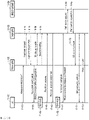
- FIG. 1F is a diagram illustrating signaling procedures of performing handover proposed in the present disclosure in a next-generation mobile communication system.
- a UE 1f-01 in an RRC connected mode reports cell measurement information (Measurement Report) to a current source gNB (source eNB) 1f-02 when a periodic or specific event is satisfied (1f-05).
- the source gNB 1f-02 determines whether the UE 1f-01 performs handover to an adjacent cell, based on the measurement information.
- the handover is a technique for changing the source gNB 1f-02, which provides a service to the UE 1f-01 in a connected mode state, to another gNB (or another cell of the same gNB).
- the source gNB 1f-02 When the source gNB 1f-02 determines handover, the source gNB 1f-02 requests handover by transmitting a handover (HO) request message (for example, a handover preparation information message) to a new gNB that will provide a service to the UE 1f-01, that is, a target gNB 1f-03 (1f-10).
- HO handover
- the target gNB 1f-03 accepts the handover request, the target gNB 1f-03 transmits an HO request Ack message (for example, a handover command message) to the source gNB 1f-02 (1f-15).
- the source gNB 1f-02 that has received the message transmits, to the UE 1f-01, a handover command message (an RRCReconfiguration message included in a dedicated control channel (DCCH) of the HO request Ack message or the HO command message) (1f-20).
- the source gNB 1f-02 extracts the HO command message from the message received from the target gNB 1f-03 and transmits the extracted HO command message to the UE 1f-01 by using an RRC connection reconfiguration message (1f- 20).
- the present disclosure proposes a method of determining an efficient DAPS handover method proposed in the present disclosure by using two messages (the handover preparation information message (1f-10) and the handover command message (1f-15)) when the source gNB 1f-02 transmits the handover preparation information message 1f-10 and, in response thereto, the target gNB 1f-03 transmits the handover command message 1f-15 to the source gNB 1f-02.
- a first embodiment of determining the efficient DAPS handover method proposed by the present disclosure is as follows.
- a subject that determines the DAPS handover method may be the source gNB 1f-02. Also, in the first embodiment of the present disclosure, in case that the source gNB 1f-02 requests the DAPS handover method from the target gNB 1f-03, the target gNB 1f-03 may always indicate or perform the DAPS handover method.
- a second embodiment of determining the efficient DAPS handover method proposed by the present disclosure is as follows.
- a subject that determines the DAPS handover method may be the target gNB 1f-03. Also, in the second embodiment of the present disclosure, in case that the source gNB 1f-02 requests the DAPS handover method to the target gNB 1f-03 by using the indicator, the target gNB 1f-03 may reject or accept the request or indicate the source gNB 1f-02 by indicating another handover method in the handover command message.
- a third embodiment of determining the efficient DAPS handover method proposed by the present disclosure is as follows.
- a subject that determines the DAPS handover method may be the target gNB.
- the target gNB 1f-03 may identify the capability of the UE 1f-01, and may determine the handover method (for example, the DAPS handover method) according to whether the target gNB 1f-03 is able to support the DAPS handover method, the amount of current transmission resources, or scheduling.
- the source gNB 1f-02 may transmit a message for requesting handover to the target gNB 1f-03 by including current bearer configuration information of the UE 1f-01, security key information, cell group configuration information, or capability information of the UE 1f-01 in the handover preparation information message.
- the source gNB 1f-02 may know in advance whether the target gNB 1f-03 supports the DAPS handover method by sharing the capabilities of the target gNB 1f-03 in an implementation manner. In case that the target gNB 1f-03 indicates to perform the DAPS handover method, the source gNB 1f-02 may perform quick or early data forwarding.
- the target gNB 1f-03 may receive the handover preparation information message, and may determine the handover method (for example, the DAPS handover method) according to the capability information of the UE 1f-01, whether the target gNB 1f-03 is able to support the DAPS handover method, the amount of current transmission resources, or scheduling. In case that the target gNB 1f-03 determines the DAPS handover method, the target gNB 1f-03 may transmit the handover command message by including the indicator indicating the DAPS handover method in the handover command message.
- the target gNB 1f-03 may transmit the handover command message by including the indicator indicating the DAPS handover method in the handover command message.
- the target gNB 1f-03 may configure the RRCReconfiguration message to indicate handover to the UE 1f-01, wherein the RRCReconfiguration message includes the indicator indicating the DAPS handover method when the DAPS handover is determined, includes the indicator indicating another handover method when handover methods other than the DAPS handover are determined, and includes bearer configuration information, security key information, or cell group configuration information, or system information necessary when the UE 1f-01 performs the DAPS handover method or another handover method.
- the target gNB 1f-03 may transmit the configured RRCReconfiguration message to the source gNB 1f-02 by including the configured RRCReconfiguration message in the DL-DCCH message of the handover command message.
- the target gNB 1f-03 may indicate the DAPS handover method for each bearer (DRB or SRB).
- the source gNB 1f-02 may identify whether the DAPS handover is determined by identifying the indicator included in the handover command message. In case that the DAPS handover method is indicated, the source gNB 1f-02 may perform the DAPS handover method, may extract the RRCReconfiguration message included in the handover command message, and may indicate handover by transmitting the RRCReconfiguration message to the UE 1f-01.
- the source gNB 1f-02 may perform another handover method indicated by the target gNB 1f-03. Also, the source gNB 1f-02 may extract the RRCReconfiguration message included in the handover command message and indicate handover by transmitting the RRCReconfiguration message to the UE 1f-01.
- the source gNB 1f-02 may read the RRCReconfiguration message included in the handover command message, may identify which handover method is indicated by the target gNB 1f-03, may identify whether the DAPS handover method is determined, and in case that another handover method is indicated, may perform the indicated handover method.
- the source gNB 1f-02 may identify the indicated DAPS handover method for each bearer and perform the DAPS handover method for each bearer (DRB or SRB).
- a new embodiment may be extended by combining the methods of the first embodiment, the second embodiment, or the third embodiment of determining the efficient DAPS handover method proposed in the present disclosure.
- the gNB may indicate to the UE 1f-01 the efficient handover method (DAPS handover method) proposed in the present disclosure.
- the gNB may set the DAPS handover method for each bearer (DRB or SRB) of the UE 1f-01.
- a new indicator indicating an efficient handover method may be defined in bearer configuration information, PDCP configuration information, or RLC configuration information for each bearer identifier or logical channel identifier, and the gNB may indicate the efficient handover method to the UE 1f-01 for each bearer or each logical channel identifier by using the indicator.
- other handover methods are indicated together to prevent data loss or transmission delay that may occur during handover (examples of the other handover methods include a conditional handover method (a method in which a plurality of target cells are set and a plurality of conditions are set in the UE 1f-01, wherein, when the above conditions are satisfied in a cell selection or reselection procedure, the UE 1f-01 performs a handover procedure to one target cell) or a handover method without a random access procedure).
- a conditional handover method a method in which a plurality of target cells are set and a plurality of conditions are set in the UE 1f-01, wherein, when the above conditions are satisfied in a cell selection or reselection procedure, the UE 1f-01 performs a handover procedure to one target cell
- the UE 1f-01 Upon receiving the RRCReconfiguration message, the UE 1f-01 stops or continues to perform data transmission and reception with the source gNB 1f-02 according to the set handover method, and starts a T304 timer. In case that the UE 1f-01 does not succeed in handover to the target gNB 1f-03 for a certain time (for example, when the T304 timer has expired), T304 returns to the original setting of the UE 1f-01 and switches the UE 1f-01 to an RRC idle state. Also, the UE 1f-01 may trigger the RRC connection re-establishment procedure.
- the UE 1f-01 may perform fallback and report a handover failure to the source gNB 1f-02.
- the source gNB 1f-02 transmits a sequence number (SN) status for uplink/downlink data for each bearer (for example, each RLC UM bearer or each RLC AM bearer).
- SN sequence number
- the source gNB 1f-02 transmits the downlink or uplink data to the target gNB 1f-03 (1f-30, 1f-35).
- the UE 1f-01 attempts random access to the target cell indicated by the source gNB 1f-02 (1f-40).
- the random access is for notifying the target cell that the UE 1f-01 moves through handover and matching uplink synchronization.
- the UE 1f-01 transmits, to the target cell, a preamble ID provided from the source gNB 1f-02 or a preamble corresponding to a randomly selected preamble ID.
- the UE 1f-01 monitors whether a random access response (RAR) message is transmitted from the target cell.
- RAR random access response
- the UE 1f-01 When the RAR is received during the monitoring time interval (1f-45), the UE 1f-01 transmits an HO complete message to the target gNB 1f-03 as an RRC reconfiguration complete message (1f-55). As described above, when the UE 1f-01 successfully receives the RAR from the target gNB 1f-03, the UE 1f-01 stops the T304 timer (1f-50).
- the target gNB 1f-03 requests the core network 1f-04 (that is, MME/S-GW/AMF) to modify the paths of the bearers so as to modify the paths of the bearers set as the source gNB 1f-02 (1f-60, 1f-65), and notifies the source gNB 1f-02 to delete the UE context of the UE 1f-01 (1f-70).
- the target gNB 1f-03 may transmit an RRC message (for example, an RRCReconfiguration message) 1f-71 to the UE 1f-01 so as to indicate the release of the connection with the source gNB 1f-02 by using an indicator.
- the target gNB 1f-03 may transmit MAC control information, RLC control information, or PDCP control information to the UE 1f-01 so as to indicate the release of the connection with the source gNB 1f-02.
- the UE 1f-01 attempts to receive data from the start time point of the RAR window with respect to the target gNB 1f-03.
- the UE 1f-01 transmits an RRC reconfiguration complete message to the target gNB 1f-03, receives a downlink transmission resource or an uplink transmission resource, and starts data transmission and reception with the target gNB 1f-03.
- methods applicable when the gNB configures or indicates the second embodiment (DAPS handover method) proposed in the present disclosure to the UE 1f-01 by using the handover command message or the RRC message (for example, RRCReconfiguration message) are as follows.
- the gNB configures the DAPS handover method in the UE 1f-01, or when the UE 1f-01 receives, from the gNB, the handover command message that configures the DAPS handover method a method applied by applying one or more of the following methods may be performed.
- the gNB When attempting to indicate or configure handover to the UE 1f-01, the gNB (the source gNB 1f-02, the target gNB 1f-03, the LTE base station, or the NR base station) may include mobility Control Info or Reconfiguration With Sync configuration information in the RRCReconfiguration message.
- the gNB may define an indicator in SRB-ToAddMod or DRB-ToAddMod of SRB-ToAddModList or DRB-ToAddModList in the bearer configuration information (Radio Resource Config Dedicated or Radio Bearer Config) of the RRCReconfiguration message, and may indicate the DAPS handover method for each bearer (each SRB or DRB) through the defined indicator.
- the gNB may define an indicator in pdcp-config of SRB-ToAddMod or DRB-ToAddMod and indicate the DAPS handover method for each bearer.
- the LTE base station may define the indicator in SRB-ToAddMod for the SRB, may configure the DAPS handover method for each bearer, may define the indicator in pdcp-config of DRB-ToAddMod for the DRBs, and may configure the DAPS handover method for each bearer.
- the UE 1f-01 may perform the DAPS handover method for the bearer in which the DAPS handover method is configured, for each bearer, according to the configuration indicated in the received handover command message (RRCReconfiguration message), and may perform a general handover method for the bearer for which the DAPS handover method is not configured.
- RRCReconfiguration message the configuration indicated in the received handover command message
- mobility Control Info or Reconfiguration With Sync configuration information of the handover command message includes an indicator indicating or configuring the type of the handover method for the UE 1f-01 (for example, MakeBeforeBreak handover, rach-skip handover, RACH-less handover, or conditional handover CHO) and the DAPS handover method is configured for each bearer
- the UE 1f-01 may apply the DAPS handover method in preference to other types of handover methods when performing the handover procedure for each bearer.
- the UE 1f-01 may perform the DAPS handover method for the bearer for which the DAPS handover method is configured, for each bearer, according to the configuration.
- the UE 1f-01 may perform the handover method configured according to the indicator indicating or configuring the type of the handover method for the UE 1f-01 (for example, MakeBeforeBreak handover, rach-skip handover, RACH-less handover, or conditional handover CHO) in mobility Control Info or Reconfiguration With Sync configuration information of the handover command message.
- the indicator indicating or configuring the type of the handover method for the UE 1f-01 (for example, MakeBeforeBreak handover, rach-skip handover, RACH-less handover, or conditional handover CHO) in mobility Control Info or Reconfiguration With Sync configuration information of the handover command message.
- the type of other handover method for the UE 1f-01 for example, MakeBeforeBreak handover, rach-skip handover, RACH-less handover, or conditional handover CHO) in mobility Control Info or Reconfiguration With Sync configuration information of the handover command message may be set not to be indicated or configured.
- the UE 1f-01 receives the handover command message (RRCReconfiguration message) and the DAPS handover method is configured for at least one bearer or a certain bearer for each bearer in the handover command message (RRCReconfiguration message)
- the RRC layer, SDAP layer, MAC layer, PHY layer, or SRB processing method of performing the DAPS handover method proposed in the present disclosure may be applied.
- the PDCP layer or RLC layer processing method of performing the DAPS handover method proposed in the present disclosure may be applied.
- the gNB When attempting to indicate or configure handover to the UE 1f-01, the gNB (the source gNB 1f-02, the target gNB 1f-03, the LTE base station, or the NR base station) may include mobility Control Info or Reconfiguration With Sync configuration information in the RRCReconfiguration message.
- the base station may define an indicator in DRB-ToAddMod of DRB-ToAddModList in the bearer configuration information (Radio Resource Config Dedicated or Radio Bearer Config) of the RRCReconfiguration message, and may indicate the DAPS handover method for each bearer (DRB) through the defined indicator. For SRBs, a separate indicator for configuring the DAPS handover method may not be introduced.
- the SRB processing method of performing the DAPS handover method proposed in the present disclosure may be applied.
- the gNB may define an indicator in pdcp-config of DRB-ToAddMod and indicate the DAPS handover method for each bearer.
- the UE 1f-01 may perform the DAPS handover method for the bearer for which the DAPS handover method is configured, for each bearer, according to the configuration indicated in the received handover command message (RRCReconfiguration message), and may perform a general handover method for the bearer for which the DAPS handover method is not configured.
- RRCReconfiguration message the configuration indicated in the received handover command message
- mobility Control Info or Reconfiguration With Sync configuration information of the handover command message includes an indicator indicating or configuring the type of the handover method for the UE 1f-01 (for example, MakeBeforeBreak handover, rach-skip handover, RACH-less handover, or conditional handover CHO) and the DAPS handover method is configured for each bearer
- the UE 1f-01 may apply the DAPS handover method in preference to other types of handover methods when performing the handover procedure for each bearer.
- the UE 1f-01 may perform the DAPS handover method for the bearer for which the DAPS handover method is configured, for each bearer, according to the configuration.
- the UE 1f-01 may perform the handover method configured according to the indicator indicating or configuring the type of the handover method for the UE 1f-01 (for example, MakeBeforeBreak handover, rach-skip handover, RACH-less handover, or conditional handover CHO) in mobility Control Info or Reconfiguration With Sync configuration information of the handover command message.
- the indicator indicating or configuring the type of the handover method for the UE 1f-01 (for example, MakeBeforeBreak handover, rach-skip handover, RACH-less handover, or conditional handover CHO) in mobility Control Info or Reconfiguration With Sync configuration information of the handover command message.
- the type of other handover method for the UE 1f-01 for example, MakeBeforeBreak handover, rach-skip handover, RACH-less handover, or conditional handover CHO) in mobility Control Info or Reconfiguration With Sync configuration information of the handover command message may be set not to be indicated or configured.
- the UE 1f-01 receives the handover command message (RRCReconfiguration message) and the DAPS handover method is configured for at least one bearer or a certain bearer for each bearer in the handover command message (RRCReconfiguration message)
- the RRC layer, SDAP layer, MAC layer, PHY layer, or SRB processing method for performing the DAPS handover method proposed in the present disclosure may be applied.
- the PDCP layer or RLC layer processing method for performing the DAPS handover method proposed in the present disclosure may be applied.
- the gNB When attempting to indicate or configure handover to the UE 1f-01, the gNB (the source gNB 1f-02, the target gNB 1f-03, the LTE base station, or the NR base station) may include mobility Control Info or Reconfiguration With Sync configuration information in the RRCReconfiguration message.
- the gNB may define and include an indicator indicating or configuring the DAPS handover method in mobility Control Info or Reconfiguration With Sync, and may use the indicator to indicate that the DAPS handover method is configured for at least one bearer or a certain bearer.
- the gNB may define an indicator in SRB-ToAddMod or DRB-ToAddMod of SRB-ToAddModList or DRB-ToAddModList in the bearer configuration information (Radio Resource Config Dedicated or Radio Bearer Config) of the RRCReconfiguration message and may indicate the DAPS handover method for each bearer (each SRB or DRB). Also, the gNB may define an indicator in pdcp-config of SRB-ToAddMod or DRB-ToAddMod and indicate the DAPS handover method for each bearer.
- the bearer configuration information Radio Resource Config Dedicated or Radio Bearer Config
- the LTE base station may define the indicator in SRB-ToAddMod for the SRB, may configure the DAPS handover method for each bearer, may define the indicator in pdcp-config of DRB-ToAddMod for the DRBs, and may configure the DAPS handover method for each bearer.
- the UE 1f-01 may perform the DAPS handover method for the bearer for which the DAPS handover method is configured, for each bearer, according to the configuration indicated in the received handover command message (RRCReconfiguration message), and may perform a general handover method for the bearer for which the DAPS handover method is not configured.
- RRCReconfiguration message the configuration indicated in the received handover command message
- mobility Control Info or Reconfiguration With Sync configuration information of the handover command message includes an indicator indicating or configuring the type of the handover method for the UE 1f-01 (for example, MakeBeforeBreak handover, rach-skip handover, RACH-less handover, or conditional handover CHO) and the DAPS handover method is configured for each bearer
- the UE 1f-01 may apply the DAPS handover method in preference to other types of handover methods when performing the handover procedure for each bearer.
- the UE 1f-01 may perform the DAPS handover method for the bearer for which the DAPS handover method is configured, for each bearer, according to the configuration.
- the UE 1f-01 may perform the handover method configured according to the indicator indicating or configuring the type of the handover method for the UE 1f-01 (for example, MakeBeforeBreak handover, rach-skip handover, RACH-less handover, or conditional handover CHO) in mobility Control Info or Reconfiguration With Sync configuration information of the handover command message.
- the indicator indicating or configuring the type of the handover method for the UE 1f-01 (for example, MakeBeforeBreak handover, rach-skip handover, RACH-less handover, or conditional handover CHO) in mobility Control Info or Reconfiguration With Sync configuration information of the handover command message.
- the type of other handover method for the UE 1f-01 for example, MakeBeforeBreak handover, rach-skip handover, RACH-less handover, or conditional handover CHO) in mobility Control Info or Reconfiguration With Sync configuration information of the handover command message may be set not to be indicated or configured.
- the UE 1f-01 receives the handover command message (RRCReconfiguration message) and the indicator indicating or configuring the DAPS handover method is included (or configured) in mobility Control Info or Reconfiguration With Sync in the handover command message (RRCReconfiguration message)
- the RRC layer, SDAP layer, MAC layer, PHY layer, or SRB processing method of performing the DAPS handover method proposed in the present disclosure may be applied.
- the PDCP layer or RLC layer processing method of performing the DAPS handover method proposed in the present disclosure may be applied.
- the gNB When attempting to indicate or configure handover to the UE 1f-01, the gNB (the source gNB 1f-02, the target gNB 1f-03, the LTE base station, or the NR base station) may include mobility Control Info or Reconfiguration With Sync configuration information in the RRCReconfiguration message.
- the gNB may define and include an indicator indicating or configuring the DAPS handover method in mobility Control Info or Reconfiguration With Sync, and may use the indicator to indicate that the DAPS handover method is configured for at least one bearer or a certain bearer.
- the gNB may define an indicator in DRB-ToAddMod of DRB-ToAddModList in the bearer configuration information (Radio Resource Config Dedicated or Radio Bearer Config) of the RRCReconfiguration message, and may indicate the DAPS handover method for each bearer (DRB).
- DRB DRB-ToAddModList
- the bearer configuration information Radio Resource Config Dedicated or Radio Bearer Config
- a separate indicator for configuring the DAPS handover method may not be introduced. That is, in case that the UE 1f-01 receives the handover command message (RRCReconfiguration message) and the DAPS handover method is configured for at least one bearer (DRB) or a certain bearer (DRB) for each bearer in the handover command message (RRCReconfiguration message), the SRB processing method of performing the DAPS handover method proposed in the present disclosure may be applied.
- the gNB 1f-03 may define an indicator in pdcp-config of DRB-ToAddMod and indicate the DAPS handover method for each
- the UE 1f-01 may perform the DAPS handover method for the bearer for which the DAPS handover method is configured, for each bearer, according to the configuration indicated in the received handover command message (RRCReconfiguration message), and may perform a general handover method for the bearer for which the DAPS handover method is not configured.
- RRCReconfiguration message the configuration indicated in the received handover command message
- mobility Control Info or Reconfiguration With Sync configuration information of the handover command message includes an indicator indicating or configuring the type of the handover method for the UE 1f-01 (for example, MakeBeforeBreak handover, rach-skip handover, RACH-less handover, or conditional handover CHO) and the DAPS handover method is configured for each bearer
- the UE 1f-01 may apply the DAPS handover method in preference to other types of handover methods when performing the handover procedure for each bearer.
- the UE 1f-01 may perform the DAPS handover method for the bearer for which the DAPS handover method is configured, for each bearer, according to the configuration.
- the UE 1f-01 may perform the handover method configured according to the indicator indicating or configuring the type of the handover method for the UE 1f-01 (for example, MakeBeforeBreak handover, rach-skip handover, RACH-less handover, or conditional handover CHO) in mobility Control Info or Reconfiguration With Sync configuration information of the handover command message.
- the indicator indicating or configuring the type of the handover method for the UE 1f-01 (for example, MakeBeforeBreak handover, rach-skip handover, RACH-less handover, or conditional handover CHO) in mobility Control Info or Reconfiguration With Sync configuration information of the handover command message.
- the type of other handover method for the UE 1f-01 for example, MakeBeforeBreak handover, rach-skip handover, RACH-less handover, or conditional handover CHO) in mobility Control Info or Reconfiguration With Sync configuration information of the handover command message may be set not to be indicated or configured.
- the UE 1f-01 receives the handover command message (RRCReconfiguration message) and the indicator indicating or configuring the DAPS handover method is included (or configured) in mobility Control Info or Reconfiguration With Sync in the handover command message (RRCReconfiguration message)
- the RRC layer, SDAP layer, MAC layer, PHY layer, or SRB processing method of performing the DAPS handover method proposed in the present disclosure may be applied.
- the PDCP layer or RLC layer processing method of performing the DAPS handover method proposed in the present disclosure may be applied.
- the gNB When attempting to indicate or configure handover to the UE 1f-01, the gNB (the source gNB 1f-02, the target gNB 1f-03, the LTE base station, or the NR base station) may include mobility Control Info or Reconfiguration With Sync configuration information in the RRCReconfiguration message.
- the gNB may define and include an indicator indicating or configuring the DAPS handover method in mobility Control Info or Reconfiguration With Sync, and may use the indicator to indicate that the DAPS handover method is configured for at least one bearer or a certain bearer.
- the gNB may configure and include a list of bearers for which the DAPS handover method is configured in mobility Control Info or Reconfiguration With Sync, may include identifiers (SRB or DRB) of bearers for which the DAPS handover method is configured in the list of bearers, and may indicate whether to configure the DAPS handover method for each bearer. Also, the gNB may configure and include a list of bearers for which the DAPS handover method is not configured in mobility Control Info or Reconfiguration With Sync, may include identifiers (SRB or DRB) of bearers for which the DAPS handover method is not configured in the list of bearers, and may indicate whether to configure the DAPS handover method for each bearer.
- SRB or DRB identifiers
- the UE 1f-01 may perform the DAPS handover method on the bearer for which the DAPS handover method is configured, the bearer whose identifier is included in the list of bearers for which the DAPS handover method is configured, or the bearer whose identifier is not included in the list of bearers for which the DAPS handover method is not configured, for each bearer according to the configuration indicated in the received handover command message (RRCReconfiguration message), and the UE 1f-01 may perform the general handover method on the bearer for which the DAPS handover method is not configured, the bearer whose identifier is not included in the list of bearers for which the DAPS handover method is configured, and the bearer whose identifier is included in the list of bearers for which the DAPS handover method is not configured.
- mobility Control Info or Reconfiguration With Sync configuration information of the handover command message includes an indicator indicating or configuring the type of the handover method for the UE 1f-01 (for example, MakeBeforeBreak handover, rach-skip handover, RACH-less handover, or conditional handover CHO) and the DAPS handover method is configured for each bearer
- the UE 1f-01 may apply the DAPS handover method in preference to other types of handover methods when performing the handover procedure for each bearer.
- the UE 1f-01 may perform the DAPS handover method on the bearer for which the DAPS handover method is configured, the bearer whose identifier is included in the list of bearers for which the DAPS handover method is configured, or the bearer whose identifier is not included in the list of bearers for which the DAPS handover method is not configured, for each bearer, according to the configuration.
- the UE 1f-01 may perform the handover method, which is set according to the indicator indicating or configuring the type of the handover method for the UE 1f-01 (for example, MakeBeforeBreak handover, rach-skip handover, RACH-less handover, or conditional handover CHO) in mobility Control Info or Reconfiguration With Sync configuration information of the handover command message, on the bearer for which the DAPS handover method is not configured, the bearer whose identifier is not included in the list of bearers for which the DAPS handover method is configured, or the bearer whose identifier is included in the list of bearers for which the DAPS handover method is not configured.
- the indicator indicating or configuring the type of the handover method for the UE 1f-01 for example, MakeBeforeBreak handover, rach-skip handover, RACH-less handover, or conditional handover CHO
- the type of other handover method for the UE 1f-01 for example, MakeBeforeBreak handover, rach-skip handover, RACH-less handover, or conditional handover CHO) in mobility Control Info or Reconfiguration With Sync configuration information of the handover command message may be set not to be indicated or configured.
- the UE 1f-01 may apply the RRC layer, SDAP layer, MAC layer, PHY layer, or SRB processing method of performing the DAPS handover method proposed in the present disclosure.
- the UE 1f-01 may apply, for each bearer, the PDCP layer or RLC layer processing method of performing the DAPS handover method proposed in the present disclosure on the bearer for which the DAPS handover method is configured, the bearer whose identifier is included in the list of bearers for which the DAPS handover method is configure, or the bearer whose identifier is not included in the list of bearers for which the DAPS handover method is not configured.
- the gNB When attempting to indicate or configure handover to the UE 1f-01, the gNB (the source gNB 1f-02, the target gNB 1f-03, the LTE base station, or the NR base station) may include mobility Control Info or Reconfiguration With Sync configuration information in the RRCReconfiguration message.
- the gNB may define and include an indicator indicating or configuring the DAPS handover method in mobility Control Info or Reconfiguration With Sync, and may use the indicator to indicate that the DAPS handover method is configured for at least one bearer or a certain bearer.
- the gNB may configure and include a list of bearers for which the DAPS handover method is configured in mobility Control Info or Reconfiguration With Sync, may include identifiers (SRB or DRB) of bearers for which the DAPS handover method is configured in the list of bearers, and may indicate whether to configure the DAPS handover method for each bearer. Also, the gNB may configure and include a list of bearers for which the DAPS handover method is not configured in mobility Control Info or Reconfiguration With Sync, may include identifiers (SRB or DRB) of bearers for which the DAPS handover method is not configured in the list of bearers, and may indicate whether to configure the DAPS handover method for each bearer.
- SRB or DRB identifiers
- a separate indicator for configuring the DAPS handover method may not be introduced for SRBs. That is, in case that the UE 1f-01 receives the handover command message (RRCReconfiguration message) and the DAPS handover method is configured for at least one bearer (DRB) or a certain bearer (DRB) for each bearer in the handover command message (RRCReconfiguration message), the SRB processing method of performing the DAPS handover method proposed in the present disclosure may be applied.
- the UE 1f-01 may perform the DAPS handover method on the bearer for which the DAPS handover method is configured, the bearer whose identifier is included in the list of bearers for which the DAPS handover method is configured, or the bearer whose identifier is not included in the list of bearers for which the DAPS handover method is not configured, for each bearer according to the configuration indicated in the received handover command message (RRCReconfiguration message), and the UE 1f-01 may perform the general handover method on the bearer for which the DAPS handover method is not configured, the bearer whose identifier is not included in the list of bearers for which the DAPS handover method is configured, and the bearer whose identifier is included in the list of bearers for which the DAPS handover method is not configured.
- mobility Control Info or Reconfiguration With Sync configuration information of the handover command message includes an indicator indicating or configuring the type of the handover method for the UE 1f-01 (for example, MakeBeforeBreak handover, rach-skip handover, RACH-less handover, or conditional handover CHO) and the DAPS handover method is configured for each bearer
- the UE 1f-01 may apply the DAPS handover method in preference to other types of handover methods when performing the handover procedure for each bearer.
- the UE 1f-01 may perform the DAPS handover method on the bearer for which the DAPS handover method is configured, the bearer whose identifier is included in the list of bearers for which the DAPS handover method is configured, or the bearer whose identifier is not included in the list of bearers for which the DAPS handover method is not configured, for each bearer, according to the configuration.
- the UE 1f-01 may perform the handover method, which is set according to the indicator indicating or configuring the type of the handover method for the UE 1f-01 (for example, MakeBeforeBreak handover, rach-skip handover, RACH-less handover, or conditional handover CHO) in mobility Control Info or Reconfiguration With Sync configuration information of the handover command message, on the bearer for which the DAPS handover method is not configured, the bearer whose identifier is not included in the list of bearers for which the DAPS handover method is configured, or the bearer whose identifier is included in the list of bearers for which the DAPS handover method is not configured.
- the indicator indicating or configuring the type of the handover method for the UE 1f-01 for example, MakeBeforeBreak handover, rach-skip handover, RACH-less handover, or conditional handover CHO
- the type of other handover method for the UE 1f-01 for example, MakeBeforeBreak handover, rach-skip handover, RACH-less handover, or conditional handover CHO) in mobility Control Info or Reconfiguration With Sync configuration information of the handover command message may be set not to be indicated or configured.
- the UE 1f-01 may apply the RRC layer, SDAP layer, MAC layer, PHY layer, or SRB processing method of performing the DAPS handover method proposed in the present disclosure.
- the UE 1f-01 may apply, for each bearer, the PDCP layer or RLC layer processing method of performing the DAPS handover method proposed in the present disclosure on the bearer for which the DAPS handover method is configured, the bearer whose identifier is included in the list of bearers for which the DAPS handover method is configure, or the bearer whose identifier is not included in the list of bearers for which the DAPS handover method is not configured.
- the present disclosure proposes seamless handover methods capable of minimizing a data interruption time due to handover or reducing a data interruption time to 0 ms in a next-generation mobile communication system.
- the UE 1f-01 may configure a plurality of first bearers with the source gNB 1f-02 and may perform data transmission and reception (uplink or downlink data transmission and reception) through the protocol layers (a PHY layer, a MAC layer, an RLC layer, or a PDCP layer) of the bearers, but it is assumed that the UE 1f-01 has one bearer in the drawings and description for convenience of description.
- protocol layers a PHY layer, a MAC layer, an RLC layer, or a PDCP layer
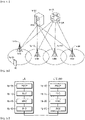
- FIG. 1G illustrates specific operations of a first embodiment of an efficient handover method of minimizing a data interruption time due to handover according to an embodiment of the present disclosure.
- the UE 1g-20 may release the connection with the source gNB 1g-05 according to the handover method indicated in the handover command message (for example, RRCReconfiguration message), may perform a random access procedure to a target gNB 1g-10, and may perform a handover procedure.
- the UE 1g-20 may continuously transmit and receive data to and from the source gNB 1g-05 so as to minimize a data interruption time that occurs during handover according to the indicated handover method.
- the UE 1g-20 may stop data transmission and reception (uplink data transmission and downlink data reception) with the source gNB 1g-05 when the UE 1g-20 performs the random access procedure to the target gNB 1g-10 according to the handover method indicated in the handover command message received from the source gNB 1g-05, when a preamble is transmitted to the target gNB 1g-10, or when data is transmitted through an uplink transmission resource for the first time on a PUCCH or PUSCH transmission resource.
- the UE 1g-20 may complete the random access procedure to the target gNB 1g-10, may transmit a handover completion message to the target gNB 1g-10, and may start data transmission and reception (uplink data transmission and downlink data reception) with the target gNB 1g-10.
- FIG. 1H illustrates specific operations of a second embodiment of an efficient handover method of minimizing a data interruption time due to handover, according to an embodiment of the present disclosure.
- a UE 1h-20 may receive a handover command message from a source gNB 1h-05 while transmitting and receiving data with the source gNB 1h-05.
- the UE 1h-20 may continuously transmit and receive data to and from the source gNB 1h-05 through protocol layers 1h-22 of a first bearer so as to minimize a data interruption time occurring during handover even when the UE 1h-20 receives the handover command message.
- the RRC layer may transmit the indicator to the PDCP layer corresponding to each bearer or the bearer for which the DAPS handover method is indicated.
- the PDCP layer may switch from a first PDCP layer structure (1i-11 or 1i-12 in FIG. 1I ) to a second PDCP layer structure (1i-20 in FIG. 1I ).
- the UE 1h-20 receives the handover command message (RRCReconfiguration message) from the gNB. Also, when switching to the second PDCP layer structure according to the configuration included in the handover command message received by the UE 1h-20, the UE 1h-20 may previously configure or establish protocol layers (a PHY layer, a MAC layer, an RLC layer, or a PDCP layer) 1h-21 of a second bearer for the target gNB 1h-10, may derive and update a security key for the target gNB 1h-10, and may configure a header (or data) compression context for the target gNB 1h-10.
- protocol layers a PHY layer, a MAC layer, an RLC layer, or a PDCP layer
- the UE 1h-20 may switch from the first PDCP layer structure or function (1i-11 or 1i-12 in FIG. 1I ) to the second PDCP layer structure or function (1i-20 in FIG. 1I ) proposed in the present disclosure for each bearer or with respect to the bearer for which the DAPS handover method is indicated.
- the first PDCP layer structure or function (1i-11 or 1i-12 in FIG. 1I When switching from the first PDCP layer structure or function (1i-11 or 1i-12 in FIG.
- the UE 1h-20 may update a reordering variable with a PDCP sequence number or count value expected to receive next, and may stop and restart the reordering timer.
- the RRC layer of the UE 1h-20 may start a first timer (for example, T304).
- the first timer may be stopped when the UE 1h-20 performs a random access procedure to the target gNB 1h-10 so as to perform handover and the random access procedure is successfully completed (for example, when a first condition proposed in the present disclosure is satisfied).
- the handover fails and the first timer has expired, in case that the connection to the source gNB 1h-05 is valid, the UE 1h-20 may perform fallback, report a handover failure to the source gNB 1h-05, and attempt connection recovery.
- the UE 1h-20 may perform an RRC connection re-establishment procedure.
- the handover command message that the UE 1h-20 receives from the source gNB 1h-05 may include information for performing configuration and establishment so that the first bearer has the same bearer identifier as the second bearer, so as to prevent a data interruption time from occurring for each bearer. Also, in the second embodiment of the present disclosure, the PDCP layer of the first bearer and the PDCP layer of the second bearer may logically operate as one PDCP layer, and a more detailed operating method therefor will be described with reference to FIG. 1I .
- the UE 1h-20 may transmit uplink data to only one of the source gNB 1h-05 and the target gNB 1h-10 so as to prevent a problem of coverage reduction due to insufficient transmission power of the UE 1h-20 or a problem (link selection) of determining which gNB to request a transmission resource to and to transmit uplink data to when transmitting uplink data.
- the UE 1h-20 when the UE 1h-20 does not have the capability (dual uplink transmission) to simultaneously transmit uplink data to different gNBs at different frequencies or the same frequency, the UE 1h-20 may transmit uplink data to only one of the source gNB 1h-05 and the target gNB 1h-10 in one time unit.
- the UE 1h-20 may perform a scheduling request to only one of the source gNB 1h-05 and the target gNB 1h-10, may transmit a report on the size of data to be transmitted in the PDCP layer (for example, a buffer status report) to only one of the source gNB 1h-05 and the target gNB 1h-10, and may receive an uplink transmission resource and transmit uplink data to only one gNB. Also, even when the UE 1h-20 receives the handover command message from the source gNB 1h-05, the MAC layer of the first bearer may not be reset so as to prevent data loss by continuing data transmission and reception due to HARQ retransmission. Also, in the case of the RLC layer of the AM mode, RLC retransmission may be continuously performed.
- the UE may continuously transmit or receive data to or from the source gNB 1h-05 only for the PDCP layer, the RLC layer, or the MAC layer corresponding to the bearer or logical channel identifier indicated in the second embodiment (DAPS handover method) in the handover command message, or only for data corresponding to the bearer or logical channel identifier.
- the UE may continuously transmit or receive RLC control data (RLC status report), PDCP control data (ROHC feedback or PDCP status report), or HARQ retransmission to or from the source gNB 1h-05 only for the PDCP layer, the RLC layer, or the MAC layer corresponding to the bearer or logical channel identifier indicated in the second embodiment (DAPS handover method) in the handover command message.
- RLC status report RLC status report
- PDCP control data ROHC feedback or PDCP status report
- HARQ retransmission to or from the source gNB 1h-05 only for the PDCP layer, the RLC layer, or the MAC layer corresponding to the bearer or logical channel identifier indicated in the second embodiment (DAPS handover method) in the handover command message.
- the UE may stop data transmission or reception with the source gNB 1h-05 for the PDCP layer, the RLC layer, or the MAC layer corresponding to the bearer or logical channel identifier not indicated in the second embodiment (DAPS handover method) in the handover command message.
- the UE may receive the handover command message.
- the DAPS handover method proposed in the present disclosure is indicated in the handover command message
- the DAPS handover method is indicated for specific bearers
- the DAPS handover method is configured for at least one bearer
- the DAPS handover method is configured for a certain bearer, or in case that mapping information between QoS flow and bearer is newly configured
- the UE may switch from a first SDAP layer structure or function 1j-10 to a second SDAP layer structure or function 1j-20 proposed in the present disclosure for each bearer or with respect to the bearer indicated by the DAPS handover method.
- the mapping information between the first QoS flow and the bearer for the existing source gNB is maintained, and uplink data to be transmitted to the source gNB and downlink data to be received from the source gNB are processed.
- the second mapping information between the QoS flow and the bearer newly configured in the handover command message may be configured for the target gNB, and may be used to process uplink data to be transmitted to the target gNB and downlink data to be received from the target gNB.
- the first mapping information between the QoS flow and the bearer or the second mapping information between the QoS flow and the bearer for the source gNB is maintained, and data for the source gNB and data for the target gNB are separately processed.
- the SDAP layer in the second SDAP layer structure may distinguish whether data received from a lower layer is data received from the source gNB or data received from the target gNB through a 1-bit indicator of an SDAP header, a 1-bit indicator of a PDCP header, or information indicated by the PDCP layer.
- the gNB indicates the DAPS handover method to the UE for each bearer by using the handover command message
- the gNB may always indicate the DAPS handover method for a default bearer (default DRB).
- the gNB may enable the UE to always transmit uplink data to the default bearer.
- the DAPS handover method is not configured in the default bearer, uplink data transmission for the new QoS flow generated during handover is impossible. Therefore, a data interruption time may occur.
- the UE may apply the SDAP layer configuration information or the second mapping information between the QoS flow and the bearer when the first condition proposed in the present disclosure is satisfied.
- the UE may maintain and apply only the first mapping information between the QoS flow and the bearer corresponding to the bearer indicated in the second embodiment when the first mapping information between the QoS flow and the bearer for the source gNB is maintained.
- the first mapping information between the QoS flow and the bearer corresponding to the bearer not indicated in the second embodiment may be released or not applied.
- the UE applies the SDAP layer configuration information or the second mapping information between the QoS flow and the bearer for data transmission or reception with the target gNB when the first condition proposed in the present disclosure is satisfied.
- the UE 1h-20 may perform a random access procedure the target gNB 1h-10 indicated in the handover command message through the protocol layers of the second bearer. Even when the UE 1h-20 performs the random access procedure through the protocol layers of the second bearer, the UE 1h-20 may continue to perform data transmission or reception (uplink data transmission or downlink data reception) with the source gNB 1h-05 through the protocol layers of the first bearer. In second operation, the UE 1h-20 performs a cell selection or reselection procedure, and performs the random access procedure on the target cell indicated in the handover command message (RRCReconfiguration message) received from the source gNB 1h-05.
- RRCReconfiguration message the random access procedure on the target cell indicated in the handover command message
- the UE 1h-20 may stop transmitting uplink data to the source gNB 1h-05 through the protocol layers 1h-22 of the first bearer with respect to the bearer for which the DAPS handover method is configured, and may transmit uplink data to the target gNB 1h-10 through the protocol layers 1h-21 of the second bearer. At this time, the UE 1h-20 may continue to receive downlink data from the source gNB 1h-05 and the target gNB 1h-10 through the protocol layers of the first bearer and the second bearer.
- Third operation may be operation in which the UE 1h-20 switches uplink transmission from the source gNB 1h-05 to the target gNB 1h-10 when the first condition is satisfied. Specifically, the UE 1h-20 transmits uplink data to the source gNB 1h-05 through the first bearer until the first condition is satisfied, and when the first condition is satisfied, the UE 1h-20 stops transmitting uplink data to the source gNB 1h-05 through the first bearer and starts to transmit uplink data to the target gNB 1h-10 through the second bearer.
- the PDCP layer may stop uplink data transmission through the first bearer and switch to start uplink data transmission through the second bearer. Also, as in the PDCP layer structure proposed in FIG.
- the receiving PDCP layer 1h-21 of the second bearer may be driven as a single device with the receiving PDCP layer 1h-22 of the first bearer, and may continuously perform seamless data reception from the source gNB 1h-05 or the target gNB 1h-10 by using the stored transmission/reception data, sequence number information, or information such as header compression and decompression context.
- the first condition may be one of the following conditions. The first condition below proposes an uplink data transmission switching time point at which a transmission resource is most efficiently used and a data interruption time is minimized as much as possible.
- the PDCP layer when the PDCP layer receives, from the upper layer (for example, the RRC layer) or the lower layer (for example, the MAC layer), the indicator that the first condition is satisfied, or the indicator to switch uplink data transmission from the source gNB 1h-05 to the target gNB 1h-10 (for example, in case that the DAPS handover method is indicated), the PDCP layer may perform the protocol layer operation proposed below so as to effectively perform switching of uplink data transmission, and may perform one or more of the following operations so as to prevent data loss due to uplink data transmission.
- the PDCP layer may perform the protocol layer operation proposed below so as to effectively perform switching of uplink data transmission, and may perform one or more of the following operations so as to prevent data loss due to uplink data transmission.
- the following operations may be applied to the PDCP layer connected to an AM DRB or a UM DRB (an RLC layer operating in an AM mode or an RLC layer operating in a UM mode).
- the PDCP layer may notify that there is data to be transmitted by indicating the size or amount of data to be transmitted (for example, PDCP data volume) to the MAC layer of the first bearer for the source gNB 1h-05, and may perform uplink data transmission to the source gNB 1h-05.
- the MAC layer of the first bearer for the source gNB 1h-05 may perform a scheduling request or a buffer status reporting procedure so as to receive an uplink transmission resource allocated to the source gNB 1h-05.
- uplink data transmission switching to the target gNB 1h-10 may be performed as follows for the bearer for which the DAPS handover method is configured.
- the UE may perform one of the following methods for the bearer for which the DAPS handover method is not configured.
- the UE may continue to receive downlink data from the source gNB 1h-05 or the target gNB 1h-10 through the protocol layers of the first bearer for the source gNB 1h-05 or the second bearer for the target gNB 1h-10.
- the handover command message for example, the RRCReconfiguration message
- the RLC status report rather than data may be allowed to continuously perform uplink transmission to the source gNB 1h-05 (or the target gNB 1h-10) for the AM bearers through the protocol layers of the first bearer (or the second bearer).
- the UE may continue to transmit HARQ ACK or HARQ NACK information, RLC status report (ACK or NACK information), or PDCP control data (for example, PDCP status report or ROHC feedback information) through the protocol layers of the first bearer (or the second bearer), so that downlink data is seamlessly received from the source gNB 1h-05 (or the target gNB 1h-10), or the source gNB 1h-05 (or the target gNB 1h-10) efficiently transmits downlink data.
- the UE in third operation 1h-03, even when the first condition is satisfied and the UE 1h-20 stops transmitting uplink data to the source gNB 1h-05 through the protocol layers 1h-22 of the first bearer and switches to start to transmit uplink data to the target gNB 1h-10 through the protocol layers 1h-21 of the second bearer, the UE may continue to perform data transmission due to HARQ retransmission of the MAC layer or data transmission due to retransmission of the AM mode RLC layer so as to prevent data loss to the source gNB 1h-05.
- the source gNB 1h-05 or the target gNB 1h-10 may allocate the transmission resources to the UE by dividing the time, so as to prevent collision between the uplink transmission resource to the target gNB 1h-10 and the uplink transmission resource to the source gNB 1h-05.
- the UE may prioritize uplink transmission resource to the source gNB 1h-05 and perform data transmission to the source gNB 1h-05 so as to maintain or downlink data transmission or continuously receive downlink data from the source gNB 1h-05 without problems.
- the UE may prioritize uplink transmission resource to the target gNB 1h-10 and perform data transmission to the target gNB 1h-10 so as to maintain downlink data transmission from the target gNB 1h-10.
- the UE receives the handover command message, or is indicated for each bearer
- the UE or the bearer to which the DAPS handover is indicated may perform the scheduling request through the first protocol layer until the first condition is satisfied, may transmit the buffer status report to the source gNB 1h-05, may receive the uplink transmission resource, and may transmit the uplink data.
- the UE may receive downlink data from the source gNB 1h-05.
- the UE may no longer transmits data to the source gNB 1h-05, may switch the uplink to perform the scheduling request through the second protocol layer, may transmit the buffer status report to the target gNB 1h-10, may receive the uplink transmission resource, and may transmit uplink data to the target gNB 1h-10.
- the UE may continue to receive downlink data from the source gNB 1h-05. Even after uplink transmission switching, HARQ ACK or HARQ NACK, RLC status report, or PDCP control data (for example, PDCP status report or ROHC feedback information) corresponding to the downlink data may be continuously transmitted. Also, even when the first condition is satisfied, the UE may continue to receive downlink data from the source gNB 1h-05 or the target gNB 1h-10.
- the UE 1h-20 may stop receiving downlink data from the source gNB 1h-05 through the protocol layers 1h-22 of the first bearer, and may release the connection with the source gNB 1h-05.
- the second condition may be one of the following conditions.
- the PDCP layer 1h-21 of the second bearer may continue to perform seamless data transmission or reception with the target gNB 1h-10 by using information such as transmission or reception data, sequence number information, or header compression and decompression context, which is stored in the PDCP layer 1h-22 of the first bearer.
- the indicator indicating that the second condition is satisfied may be indicated to the PDCP layer of the UE or the bearer performing the DAPS handover method.
- the second embodiment of the efficient handover method proposed in the present disclosure may be successfully completed by performing one or more of the following procedures on the bearer or the UE for which the DAPS handover method is configured.
- the transmitting or receiving PDCP layer may discard or release the security key or header compression contexts for the source gNB 1h-05.
- the gNB may define indicators for the embodiments proposed in the present disclosure in the handover command message (for example, the RRCReconfiguration message), and may indicate to the UE which embodiment to trigger the handover procedure corresponding to.
- the UE may perform the handover procedure according to the handover method indicated in the handover command message. For example, the UE may perform handover to the target gNB 1h-10 while minimizing a data interruption time by performing the second embodiment (DAPS handover method) of the efficient handover method proposed in the present disclosure.
- the indicators for the embodiments proposed in the present disclosure may be defined for each bearer.
- Which embodiment to be applied to the bearer during handover and which bearer to which the embodiment is applied during handover may be more specifically indicated. For example, it may be indicate to apply the second embodiment of the present disclosure only to the AM bearer in which the RLC layer driven in the AM mode is running, or it may be extended and applied to the UM bearer in which the RLC layer driven in the UM mode is running. Also, it may be assumed that the embodiments proposed in the present disclosure are applied to DRB.
- the UE when necessary (for example, when the UE maintains the SRB for the source gNB 1h-05 and fails handover to the target gNB 1h-10, and the handover failure message is reported or restored to the SRB for the source gNB 1h-05, it may be extended and applied to the SRB.
- the MAC layer of the first bearer and the MAC layer of the second bearer may each operate separate discontinuous reception (DRX) cycles to reduce battery consumption of the UE. That is, the UE may continue to apply the DRX cycle of the MAC layer when transmitting and receiving data through the protocol layers of the first bearer even after receiving the handover command message.
- the UE may stop DRX according to the first condition or the second condition of the present disclosure. Also, the UE may separately operate the application of the DRX cycle to the MAC layer of the second bearer according to the indication of the target gNB 1h-10.
- the UE stops uplink transmission to the source gNB 1h-05 through the protocol layers of the first bearer and stops downlink data reception from the source gNB 1h-05 means that the UE re-establishes, resets, or releases the protocol layers (PHY layer, MAC layer, RLC layer, or PDCP layer) of the first bearer.
- the UE configures the first bearer for the source gNB 1h-05 or the second bearer for the target gNB 1h-10. It may be easily extended to the case in which the UE configures a plurality of first bearers for the source gNB 1h-05 or a plurality of second bearers for the target gNB 1h-10, and the same may be applied. According to another method, it may be easily extended to the case in which a plurality of bearers for a plurality of target gNBs 1h-10 are configured, and the same may be applied. For example, the UE may perform the handover procedure to the first target gNB 1h-10 to configure second bearers.
- the UE performs the handover procedure to the second target gNB 1h-10 to configure second bearers.
- the UE may search for and determine one cell satisfying a certain condition (for example, a certain signal intensity or more) for itself from among the target gNBs 1h-10, and may perform the handover procedure thereon.
- a certain condition for example, a certain signal intensity or more
- FIG. 1l is a diagram illustrating structures of an efficient PDCP layer applied to the DAPS handover method, which is the second embodiment of the efficient handover method proposed in the present disclosure, and a method of applying the structures.
- FIG. 1l proposes a specific structure and functions of the efficient PDCP layer applied to the DAPS handover method, which is the second embodiment of the efficient handover method proposed in the present disclosure, and the structures of the PDCP layers proposed below may be applied to different PDCP layer structures for each bearer at different times while performing the DAPS handover procedure.
- the UE processes, transmits, or receives data by applying the first PDCP layer structure and function 1i-11 or 1i-12 proposed in the present disclosure for each bearer (1i-01).
- the UE receives the handover command message from the gNB and indicates the DAPS handover method proposed in the present disclosure in the handover command message, or in case that the DAPS handover method is indicated for specific bearers, the UE processes, transmits, or receives data by applying the second PDCP layer structure and function 1i-20 proposed in the present disclosure to each bearer or the bearers in which the DAPS handover method is indicated (1i-02).
- the UE may switch from the first PDCP layer structure or function 1i-11 or 1i-12, which has been used for each bearer, to the second PDCP layer structure or function 1i-20 proposed in the present disclosure for each bearer or with respect to the bearer in which the DAPS handover method is indicated.
- the UE may switch from the first PDCP layer structure or function 1i -11 or 1i-12, which has been used for each bearer, to the second PDCP layer structure or function 1i-20 proposed in the present disclosure, for each bearer or with respect to the bearer in which the DAPS handover method is indicated (1i -02).
- the UE may update the reordering variable with the PDCP sequence number or count value expected to receive next when the UE switches from the first PDCP layer structure or function 1i-11 or 1i-12 to the second PDCP layer structure or function 1i-20 proposed in the present disclosure, for each bearer or with respect to the bearer in which the DAPS handover method is indicated, and may stop and restart the reordering timer.
- the UE may release the first bearers for the source gNB, and may switch again from the second PDCP layer structure and function 1i-20 applied to each bearer or the bearer in which the DAPS handover method is indicated to the first PDCP layer structure and function 1i -11 or the 1i-12.
- the UE may initialize reordering variables and stop and initialize the reordering timer.
- the UE may perform the deciphering procedure or header (or data) decompression by applying the security key or header decompression context for the source gNB to the data stored in the buffer for reordering (for example, the data received from the source gNB), and may discard the security key or header decompression context for the source gNB.
- the UE may transmit the processed data to the upper layer in ascending order. That is, in case that the second condition is satisfied, the UE may perform the deciphering procedure or header (or data) decompression by applying the security key or header decompression context for the source gNB to the data stored in the buffer for reordering (for example, the data received from the source gNB), and may discard the security key or header decompression context for the source gNB.
- the UE may release the first bearers for the source gNB, and may switch from the second PDCP layer structure and function 1i-20 applied to each bearer or the bearer in which the DAPS handover method is indicated to the third PDCP layer structure and function the 1i-30.
- the UE may use the reordering variables and the reordering timer without stopping or initializing the reordering variables and the reordering timer.
- the UE may perform the deciphering procedure or header (or data) decompression by applying the security key or header decompression context for the source gNB to the data stored in the buffer for reordering (for example, the data received from the source gNB), and may discard the security key or header decompression context for the source gNB.
- the UE may transmit the processed data to the upper layer in ascending order. That is, in case that the second condition is satisfied, the UE may perform the deciphering procedure or header (or data) decompression by applying the security key or header decompression context for the source gNB to the data stored in the buffer for reordering (for example, the data received from the source gNB), and may discard the security key or header decompression context for the source gNB.
- the UE when the UE performs handover by applying the first PDCP layer structure and function 1i-11 or 1i-12, the second PDCP layer structure and function 1i-20, or the third PDCP layer structure and function 1i-30 of the first PDCP layer, which is different from each other, for each bearer at different times, the UE may minimize a data interruption time without data loss.
- the first PDCP layer structure 1i-11 or 1i-12 proposed in FIG. 1I may have a (1-1)th PDCP layer structure, a (1-2)th PDCP layer structure, a (1-3)th PDCP layer structure, or a (1-4)th PDCP layer structure proposed below in the present disclosure, and an embodiment of the present disclosure may have the following features.
- the second PDCP layer structure 1i-20 proposed in FIG. 1I may have a (2-1)th PDCP layer structure or a (2-2)th PDCP layer structure proposed in the present disclosure, and may have the same features.
- the present disclosure proposes the second PDCP layer structure 1i-20 that is efficient in handover.
- the second PDCP layer structure may be applied to the second embodiment of the efficient handover method of minimizing the data interruption time proposed in the present disclosure.
- the UE may perform data transmission or reception with the source gNB 1i-21 through protocol layers of the first bearer (for example, an SDAP layer, a PDCP layer, an RLC layer, or a MAC layer).
- the UE may perform data transmission or reception with the target gNB 1i-22 through protocol layers of the second bearer (for example, an SDAP layer, a PDCP layer, an RLC layer, or a MAC layer).
- the PDCP layer of the first bearer and the PDCP layer of the second bearer may be configured in the UE, respectively, but logically, may operate as a single PDCP layer device, as in 1i-20.
- the single PDCP layer may divide the functions of the PDCP layer to implement the functions of an upper PDCP layer (for example, sequence number allocation function, reordering function, in-sequence delivery function, or duplicate detection function) and the functions of two lower PDCP layers for each source gNB and each target gNB (for example, deciphering or ciphering function, header (or data) compression or header (or data) decompression function, integrity protection or verification function, or duplicate detection function).
- an upper PDCP layer for example, sequence number allocation function, reordering function, in-sequence delivery function, or duplicate detection function
- two lower PDCP layers for each source gNB and each target gNB (for example, deciphering or ciphering function, header (or data) compression or
- the header (or data) compression protocol context may maintain and apply only one context for the source gNB or the target gNB for the uplink, and may maintain and apply two contexts for the source gNB or the target gNB for the downlink.
- the second PDCP layer structure (for example, the E-UTRA PDCP layer for the DAPS handover method) proposed in the present disclosure may have the following features.
- the upper transmitting PDCP layer may function to allocate the PDCP sequence number to data received from the upper layer.
- a separate security key set with each source gNB and each target gNB may be used to apply the header (or data) compression context or security key set with the source gNB to data to be transmitted to the source gNB and to apply the header (or data) compression context or security key set with the target gNB to data to be transmitted to the target gNB.
- the header (or data) compression procedure is configured, the header (or data) compression procedure is applied.
- the integrity protection procedure is applied to the PDCP headers and data (PDCP SDU), the ciphering procedure is applied, data to be transmitted to the source gNB is transmitted to the transmitting RLC layer of the first bearer, and data to be transmitted to the target gNB is transmitted to the transmitting RLC layer of the second bearer.
- the two lower transmitting PDCP layer functions 1i-21 and 1i-22 may perform parallel data processing in which the header compression, integrity protection, or ciphering procedure is performed in parallel so as to accelerate a data processing speed.
- the integrity protection or ciphering procedure may be performed by using different security keys.
- different data compression, integrity protection, or ciphering procedures may be performed by applying different compression contexts, security key, or security algorithms within the single transmitting PDCP layer.
- the out-of-window data detection or duplicate detection procedure may be independently performed on data received from each RLC layers based on PDCP sequence number or count value in the lower receiving PDCP layer functions 1i-21 and 1i-22 for the source gNB or the target gNB.
- the out-of-window data detection or duplicate detection procedure may be performed on all received data without distinguishing the RLC layers based on the PDCP sequence number or count value.
- the out-of-window data detection may be performed on all received data without distinguishing the RLC layers based on the PDCP sequence number or count value, and the duplicate detection procedure may be independently performed on data received from each RLC layer.
- the out-of-window data detection may be performed on all received data based on the PDCP sequence number or count value without distinguishing the RLC layers in order to prevent data loss for the header compression protocol.
- the duplicate detection procedure may be performed on the entire data after the deciphering procedure or integrity protection procedure or the header (or data) decompression procedure is performed on data received from each RLC layer.
- the lower functions of the receiving PDCP layer may directly apply the deciphering procedure on the received data by using a separate header (or data) compression context or security key set with each source gNB and each target gNB. Also, the lower functions of the receiving PDCP layer may apply the integrity verification procedure to the PDCP header and data (PDCP SDU) when the integrity protection is configured.
- PDCP SDU integrity verification procedure
- the header (or data) decompression procedure may be performed directly on the data received from the RLC layers of the first bearer for each source gNB without ordering. Also, the header (or data) decompression procedure may be performed directly on the data received from the RLC layers of the second bearer for each target gNB without ordering. Also, in order to distinguish between the data received from the RLC layers of the first bearer for each source gNB and the data received from the RLC layers of the second bearer for each target gNB, an indicator may be defined for each data to determine whether data is received from the source gNB or data received from the target gNB.
- a 1-bit indicator of a PDCP header, an SDAP header, or an RLC header may be defined to determine whether data is received from the source gNB or data received from the target gNB. Also, for data received from the RLC layers of the first bearer for the source gNB that has completed the header (or data) compression procedure and data received from the RLC layers of the second bearer for the target gNB, the duplicate detection procedure (the procedure of discarding all but one data (applicable including data previously received or transmitted to the upper layer) for each PDCP sequence number or count value) may be performed based on the PDCP sequence number or count value.
- the reordering procedure may be performed in ascending order based on the PDCP sequence number or count value, and data may be sequentially transmitted to the upper layer. Because the single PDCP layer may receive data from different gNBs, that is, the first bearer or the second bearer in any order, it may be necessary to always perform the reordering procedure.
- the two lower receiving PDCP layer functions may perform parallel data processing of performing the header compression, integrity protection, or ciphering procedure in parallel so as to accelerate the data processing speed based on the PDCP sequence number or count value.
- the integrity protection or ciphering procedure or the decompression procedure may be performed by using different header (or data) compression contexts or security keys.
- different data integrity protection or ciphering procedures or decompression procedures may be performed by applying different header (or data) compression contexts or security keys or security algorithms within a single transmitting PDCP layer.
- the out-of-sequence deciphering or integrity verification procedure may be performed on each received data regardless of the order of the PDCP sequence number or count value.
- the single PDCP layer may perform the ciphering or deciphering procedure with different security keys for uplink data and downlink data so as to distinguish between the layers of the first bearer (or the first RLC layer) and the layers of the second bearer (or the second RLC layer), and may perform compression or decompression by using different compression protocol contexts.
- the second PDCP layer structure (for example, the NR PDCP layer for the DAPS handover method) proposed in the present disclosure may have the following features.
- the upper transmitting PDCP layer may function to allocate the PDCP sequence number to data received from the upper layer.
- a separate security key set with each source gNB and each target gNB may be used to apply the header (or data) compression context or security key set with the source gNB to data to be transmitted to the source gNB and to apply the header (or data) compression context or security key set with the target gNB to data to be transmitted to the target gNB.
- the header (or data) compression procedure is configured, the header (or data) compression procedure is applied.
- the integrity protection procedure is applied to the PDCP headers and data (PDCP SDU), the ciphering procedure is applied, data to be transmitted to the source gNB is transmitted to the transmitting RLC layer of the first bearer, and data to be transmitted to the target gNB is transmitted to the transmitting RLC layer of the second bearer.
- the two lower transmitting PDCP layer functions 1i-21 and 1i-22 may perform parallel data processing in which the header compression, integrity protection, or ciphering procedure is performed in parallel so as to accelerate a data processing speed.
- the integrity protection or ciphering procedure may be performed by using different security keys.
- different data compression, integrity protection, or ciphering procedures may be performed by applying different compression contexts, security key, or security algorithms within the single transmitting PDCP layer.
- the out-of-window data detection or duplicate detection procedure may be independently performed on data received from each RLC layers based on PDCP sequence number or count value in the lower receiving PDCP layer functions 1i-21 and 1i-22 for the source gNB or the target gNB.
- the out-of-window data detection or duplicate detection procedure may be performed on all received data without distinguishing the RLC layers based on the PDCP sequence number or count value.
- the receiving PDCP layer may perform the out-of-window data detection on all received data without distinguishing the RLC layers based on the PDCP sequence number or count value, and may independently perform the duplicate detection procedure on data received from each RLC layer.
- the receiving PDCP layer function may perform the out-of-window data detection on all received data without distinguishing the RLC layers based on the PDCP sequence number or count value so as to prevent data loss for the header compression protocol, and may perform the duplicate detection procedure on the entire data after receiving the deciphering procedure, the integrity protection procedure, or the header (or data) decompression procedure for data received from the RLC layers.
- the lower functions of the receiving PDCP layer directly apply the deciphering procedure on the received data by using a separate header (or data) compression context or security key set with each source gNB and each target gNB, and when the integrity protection is configured, may apply the integrity verification procedure to the PDCP header and data (PDCP SDU).
- the header (or data) decompression procedure may be performed by applying the header (or data) compression context of each gNB (the source gNB or the target gNB) for each data received from each gNB (the source gNB or the target gNB) in ascending order of PDCP sequence number or count value.
- an indicator may be defined for each data to determine whether data is received from the source gNB or data received from the target gNB.
- a 1-bit indicator of a PDCP header, an SDAP header, or an RLC header may be defined to determine whether data is received from the source gNB or data received from the target gNB. Also, for data received from the RLC layers of the first bearer for the source gNB that has completed the header (or data) compression procedure and data received from the RLC layers of the second bearer for the target gNB, the duplicate detection procedure (the procedure of discarding all but one data (applicable including data previously received or transmitted to the upper layer) for each PDCP sequence number or count value) may be performed based on the PDCP sequence number or count value.
- data may be sequentially transmitted to the upper layer in ascending order based on the PDCP sequence number or count value. Because the single PDCP layer may receive data from different gNBs, that is, the first bearer or the second bearer in any order, it may be necessary to always perform the reordering procedure.
- the two lower receiving PDCP layer functions may perform parallel data processing of performing the header compression, integrity protection, or ciphering procedure in parallel so as to accelerate the data processing speed based on the PDCP sequence number or count value. Also, the two lower receiving PDCP layer functions may perform the integrity protection or ciphering procedure or the decompression procedure by using different header (or data) compression contexts or security keys. Also, logically, different data integrity protection or ciphering procedures or decompression procedures may be performed by applying different header (or data) compression contexts or security keys or security algorithms within a single transmitting PDCP layer. Also, in the lower receiving PDCP layer functions, the out-of-sequence deciphering or integrity verification procedure may be performed on each received data regardless of the order of the PDCP sequence number or count value.
- the single PDCP layer may perform the ciphering or deciphering procedure with different security keys for uplink data and downlink data so as to distinguish between the layers of the first bearer (or the first RLC layer) and the layers of the second bearer (or the second RLC layer), and may perform compression or decompression by using different compression protocol contexts.
- the present disclosure may proposes a third PDCP layer structure 1i-30 that is efficient in handover.
- the third PDCP layer structure may be applied to the second embodiment of the efficient handover method of minimizing the data interruption time proposed in the present disclosure.
- the PDCP layer function in the third PDCP layer structure proposed in the present disclosure may be the same as the second PDCP layer structure proposed in the present disclosure.
- the third PDCP layer structure may release the first bearer for the source gNB in the second PDCP layer structure.
- the third PDCP layer structure proposed in the present disclosure has the same function as the second PDCP layer structure proposed above, but may have a structure in which the first bearer for the source gNB (for example, the SDAP layer, the PDCP layer, the RLC layer, or the MAC layer) is released. Therefore, the third PDCP layer structure may release QoS mapping information of the SDAP layer for the source gNB, security key information for the source gNB of the PDCP layer, header (or data) compression context information for the source gNB, or the RLC layer or MAC layer for the source gNB.
- the first bearer for the source gNB for example, the SDAP layer, the PDCP layer, the RLC layer, or the MAC layer
- the third PDCP layer structure may release QoS mapping information of the SDAP layer for the source gNB, security key information for the source gNB of the PDCP layer, header (or data) compression context information for the source gNB, or the RLC layer or MAC layer for
- FIG. 1J is a diagram illustrating structures of an efficient SDAP layer applied to a DAPS handover method, which is the second embodiment of the efficient handover method proposed in the present disclosure, and a method of applying the structures.
- FIG. 1J proposes a specific structure and functions of the efficient SDAP layer applied to the DAPS handover method, which is the second embodiment of the efficient handover method proposed in the present disclosure, and the structures of the SDAP layers proposed below may be applied to different SDAP layer structures for each bearer at different times while performing the DAPS handover procedure.
- the UE processes, transmits, or receives data by applying the first SDAP layer structure and function 1j-10 proposed in the present disclosure for each bearer (1j-01).
- the SDAP layer may maintain and apply first mapping information between one QoS flow and the bearer for the source gNB for the transmitting uplink data or the receiving downlink data (for example, a procedure of reading SDAP header information, updating the mapping information, configuring the SDAP header, or routing or transmitting to an appropriate upper layer or a lower layer based on the first mapping information between the QoS flow and the bearer).
- the UE processes, transmits, or receives data by applying the second SDAP layer structure and function 1j-20 proposed in the present disclosure to each bearer or the bearers in which the DAPS handover method is indicated (1j-02).
- the UE may switch from a first SDAP layer structure or function 1j-10, which has been used for each bearer, to a second SDAP layer structure or function 1j-20 proposed in the present disclosure for each bearer or with respect to the bearer indicated by the DAPS handover method.
- the UE may switch from the first SDAP layer structure or function 1j-10, which has been used for each bearer, to the second SDAP layer structure or function 1j-20 proposed in the present disclosure for each bearer or with respect to the bearer in which the DAPS handover method is indicated (1j-02).
- the UE may switch from the first SDAP layer structure or function or 1i-10 to the second SDAP layer structure or function 1i-20 proposed in the present disclosure for each bearer or with respect to the bearer in which the DAPS handover method is indicated.
- the first mapping information between the QoS flow and the bearer for the existing source gNB is maintained, and uplink data to be transmitted to the source gNB and downlink data to be received from the source gNB are processed.
- the second mapping information between the QoS flow and the bearer newly configured in the handover command message may be configured for the target gNB, and the UE may use the configured information to process uplink data to be transmitted to the target gNB and downlink data to be received from the target gNB.
- the first mapping information between the QoS flow and the bearer or the second mapping information between the QoS flow and the bearer for the source gNB is maintained, and data for the source gNB and data for the target gNB are separately processed.
- the first condition proposed in the present disclosure it is necessary to switch uplink data transmission to the target gNB for the bearers in which the DAPS handover method is indicated. Therefore, a procedure of changing, switching, or reconfiguring the first mapping information between the QoS flow and the bearer for the source gNB to the second mapping information between the QoS flow and the bearer for the target gNB may be performed for the uplink.
- the UE transmits, to the target gNB, SDAP control data generated for each changed QoS flow (for example, an end marker indicating that the data is the last data for the changed QoS flow).
- SDAP control data generated for each changed QoS flow (for example, an end marker indicating that the data is the last data for the changed QoS flow).
- the SDAP layer in the second SDAP layer structure may distinguish whether data received from a lower layer is data received from the source gNB or data received from the target gNB through a 1-bit indicator of an SDAP header, a 1-bit indicator of a PDCP header, or information indicated by the PDCP layer.
- the gNB indicates the DAPS handover method for each bearer to the UE with the handover command message
- the DAPS handover method is indicated for the default bearer (default DRB).
- default DRB default DRB
- the UE may always transmit uplink data to the default bearer.
- uplink data transmission for the new QoS flow generated during handover is impossible. Therefore, a data interruption time may occur.
- the UE may release the first bearers for the source gNB, and may switch again from the second SDAP layer structure and function 1j-20 applied to each bearer or the bearer in which the DAPS handover method is indicated to the first SDAP layer structure and function 1j-10.
- the UE may switch from the second SDAP layer structure or function 1j-20 to the first SDAP layer structure or function 1j-10 proposed in the present disclosure, for each bearer or with respect to the bearer in which the DAPS handover method is indicated.
- the UE may maintain the second bearer for the target gNB or the second mapping information between the QoS flow and the bearer.
- the UE Before releasing the first bearer for the source gNB or the first mapping information between the QoS flow and the bearer, the UE may complete the data processing by applying the first mapping information between the QoS flow and the bearer to data received from the source gNB (for example, all data received from the source gNB), and then, may release the first mapping information between the QoS flow and the bearer or the first bearer.
- the UE may transmit the processed data to the upper layer in ascending order.
- the UE may process data by applying the first mapping information between the QoS flow and the bearer for the source gNB to the data stored in the buffer (for example, the data received from the source gNB) (for example, the procedure of reading SDAP header information, updating the mapping information, configuring the SDAP header, or routing or transmitting to an appropriate upper layer or lower layer based on the first mapping information between the QoS flow and the bearer), and may discard the first mapping information between the QoS flow and the bearer for the source gNB.
- the buffer for example, the data received from the source gNB
- the SDAP layer may define and apply a 1-bit indicator of a new SDAP header, a 1-bit indicator of the PDCP header, SDAP control data (for example, downlink end marker), or information indicated by the PDCP layer. Based on this, the SDAP layer may identify what kind of data the last data received from the source gNB is. Therefore, after the data processing is perform by applying the first mapping information between the QoS flow and the bearer for the source gNB to the last data received from the source gNB, the SDAP layer may discard the first mapping information between the QoS flow and the bearer for the source gNB. The SDAP layer may continue to maintain the second mapping information between the QoS flow and the bearer and process uplink data or downlink data to the target gNB based on the mapping information.
- the UE when the UE receives the handover command message in FIG. 1F and applies the bearer configuration information included in the handover command message, applying the bearer configuration information in different ways according to the handover type indicated in the handover command message is proposed.
- FIG. 1K is a diagram illustrating a method of applying bearer-specific configuration information when a DAPS handover method is configured, according to an embodiment of the present disclosure.
- the UE may generate or establish the MAC layer for the target gNB (or target cell) at the time of receiving the handover command message.
- the second handover method for example, the second embodiment of the present disclosure or the DAPS handover method
- the UE may generate or establish the MAC layer for the target gNB (or target cell) at the time of receiving the handover command message.
- the UE may continue to transmit or receive data with the source gNB only for bearers (AM bearers or UM bearers) in which the DAPS handover method is indicated through the MAC layer for the source gNB (or source cell) before until the first condition proposed in the present disclosure is satisfied from the time when the handover command message is received.
- bearers AM bearers or UM bearers
- the UE may switch the uplink data to the target gNB, and may receive downlink data from the source gNB until the connection with the source gNB is released.
- the UE may not perform data transmission or reception with the source gNB continuously or before until the first condition proposed in the present disclosure is satisfied from the time when the handover command message is received.
- one or more of the following methods may be applied, and may be modeled as in FIGS. 1K -21 or 1K-22.
- the second condition proposed in the present disclosure is satisfied and the source gNB is released, it may be modeled as 1K-31 or 1K-32.
- the SRBs configured in the MAC layer for the source gNB may be stopped when the UE receives the handover command message as proposed in the present disclosure and the second handover method (for example, the second embodiment of the present disclosure or the DAPS handover method) is indicated in the ReconfigWithSync information, when the DAPS handover method is indicated for each bearer identifier or logical channel identifier, when the DAPS handover method is configured for at least one bearer, or when the DAPS handover method is configured for a certain bearer.
- the second handover method for example, the second embodiment of the present disclosure or the DAPS handover method
- the upper layer (for example, the RRC layer device) of the UE may indicate the MAC layer for the source gNB to perform the reconfiguration (MAC reconfiguration) with configuration information except for the configuration information related to the bearer in which the DAPS handover method is not indicated in the handover command message in the configuration information of the current MAC layer.
- the upper layer (for example, the RRC layer) of the UE may indicate the MAC layer for the source gNB to perform the reconfiguration (MAC reconfiguration) with configuration information including only the configuration information related to the bearer in which the DAPS handover method is indicated in the handover command message in the configuration information of the current MAC layer.
- the MAC layer for the source gNB of the UE may maintain only the logical channel identifiers in which the DAPS handover method is indicated, or the priority bit rate or bucket size corresponding to the logical channel identifiers, and may release, no longer use, or no longer apply the logical channel identifiers corresponding to the bearer in which the DAPS handover method is not indicated, or the priority bit rate or bucket size corresponding to the logical channel identifiers.
- the upper layer (for example, the RRC layer) of the UE may perform the PDCP re-establishment procedure or RLC re-establishment procedure on the bearer in which the DAPS handover method is not indicated, may apply the PDCP configuration information or RLC configuration information configured in the handover message, or may stop the bearer.
- the upper layer of the UE may stop the bearer in the MAC layer for the source gNB, or it may be configured in the MAC layer for the target gNB (it may be configured in the MAC layer for the target gNB when the first condition is satisfied).
- the handover command message it may be indicated to the MAC layer for the target gNB so that bearer configuration information such as the logical channel identifier, priority bit rate, or bucket size configured for the target gNB with respect to the bearer in which the DAPS handover method is not indicated is configured or applied to the MAC layer for the target gNB.
- bearer configuration information such as the logical channel identifier, priority bit rate, or bucket size configured for the target gNB with respect to the bearer in which the DAPS handover method is not indicated is configured or applied to the MAC layer for the target gNB.
- the upper layer of the UE may switch the connection of the PDCP layer or the RLC layer corresponding to the bearer in which the DAPS handover method is not indicated from the MAC layer for the source gNB to the MAC layer for the target gNB.
- the MAC layer for the source gNB of the UE performs the LCP procedure for data transmission from that time point, only logical channel identifiers corresponding to the bearer in which the DAPS handover method is indicated are selected as a candidate group, and the LCP procedure may be performed thereon.
- the procedure, performed by the upper layer (for example, the RRC layer), of reconfiguring the MAC layer for the source gNB may partially reset the MAC layer for the source gNB (partial MAC reset) to perform the same procedure. For example, configuration information of the MAC layer for the bearer in which the DAPS handover method is not indicated may be initialized or released, or the application thereof may be stopped.
- the data transmission or reception with the source gNB may be performed until the first condition proposed in the present disclosure is satisfied.
- the MAC layer for the source gNB may first initialize the bit rate, may no longer apply a priority bit rate cumulative calculation procedure, and may release or stop the bearer.
- the MAC layer for the source gNB may continue to maintain the priority bit rate, and may perform the cumulative calculation procedure.
- the data transmission may be switched to the target gNB.
- the MAC layer for the target gNB may initialize the priority bit rate for the newly configured logical channel identifiers (logical channel identifiers corresponding to the bearer in which the DAPS handover method is indicated or the bearer in which the DAPS handover method is not indicated), or may start the cumulative calculation (according to another method, when the handover command message for the MAC layer for the target gNB is received, the priority bit rate may be initialized and the cumulative calculation may be started).
- the MAC layer for the target gNB may be configured or resumed to perform data transmission or reception with the target gNB, and may initialize the priority bit rate or start cumulative calculation.
- the data reception is performed from the source gNB or the target gNB until the second condition proposed in the present disclosure is satisfied.
- the MAC layer for the source gNB is reset.
- the RLC layer, the PDCP layer, or the bearer configuration information corresponding to the bearer in which the DAPS handover method connected to the MAC layer for the source gNB is not indicated may be released from the MAC layer for the source gNB.
- the RLC layer or bearer configuration information corresponding to the bearer in which the DAPS handover method is indicated may be released from the second PDCP layer structure or the MAC layer for the source gNB (1k-31 or 1k-32).
- the UE may perform a fallback procedure to the source gNB (1k-02), may resume SRB configured in the MAC layer of the source gNB, may report handover failure, may apply the existing bearer configuration information of the source gNB before receiving the handover command message again, may apply the configuration information of the original MAC layer (for example, the RRC layer may reconfigure the MAC layer configuration information used before receiving the handover command message for the MAC layer configuration), and may resume data transmission or reception with the source gNB for each bearer (1k-10).
- the upper layer (for example, the RRC layer) of the UE may indicate the RLC re-establishment procedure for the bearer in which the DAPS handover method is indicated or the bearer that is not indicated.
- configuration information of the MAC layer for the source gNB to be applied may be set as an RRC message.
- the UE in case that the UE receives the handover command message, in case that the second handover method (for example, the second embodiment of the present disclosure or the DAPS handover method) is indicated in the ReconfigWithSync information, in case that the DAPS handover method is indicated for each bearer identifier or logical channel identifier, when the DAPS handover method is configured for at least one bearer, or in case that the DAPS handover method is configured for a certain bearer, SRBs configured in the MAC layer for the source gNB may apply one or more of the following methods.
- the second handover method for example, the second embodiment of the present disclosure or the DAPS handover method
- the DAPS handover method is indicated in the ReconfigWithSync information
- SRBs configured in the MAC layer for the source gNB may apply one or more of the following methods.
- the present disclosure proposes a method of, when the UE performs the second embodiment (DAPS handover method) of the efficient handover method proposed in the present disclosure and the UE fails handover, quickly falling back to the source gNB and reconfiguring the connection by using the features of the DAPS handover method proposed above.
- the feature of the DAPS handover method proposed in the present disclosure may mean that data transmission or reception is performed while maintaining the connection with the source gNB even when the handover procedure is performed. Fallback using a wireless connection connected to an existing source gNB even when handover fails is specifically proposed in the present disclosure below.
- the UE may perform the handover procedure to the target gNB while maintaining data transmission or reception with the source gNB, as proposed in 1h-02. Also, the present disclosure proposes a procedure of falling back to the source gNB when the handover procedure to the target gNB fails.
- a method of determining whether the wireless connection between the UE and the source gNB is valid is required in order to fall back to the source gNB.
- the data interruption time excessively increases, resulting in significant data loss.
- the wireless connection between the UE and the source gNB it is also necessary to maintain the SRB configured in the UE and the source gNB.
- the present disclosure proposes new timers applicable to the handover method and specific operations of the timers. Also, according to the present disclosure, specific operations of the timers may be different from each other according to the type of the handover method indicated by the handover command message in the gNB. Also, a method of releasing or maintaining the connection with the source gNB or the SRB configuration according to the handover method is proposed.
- a first timer for example, T304
- a second timer for example, T310
- a third timer for example, T312
- a fourth timer for example, a timer for fallback
- the first timer (for example, T304), the second timer (for example, T310), the third timer (for example, T312), or the fourth timer (for example, the timer for fallback) proposed in the present disclosure may perform different operations as follows according to the type of the handover method indicated by the handover command message.
- the first timer (for example, T304) is a timer for determining whether handover has been successfully performed.
- the second timer (for example, T310) is a timer for determining whether the wireless connection is valid.
- the third timer (for example, T312) is an auxiliary timer for determining whether the wireless connection is valid, and a timer for triggering a frequency measurement procedure and reporting a frequency measurement result.
- the fourth timer (for example, the timer for fallback) is a timer for, when handover fails while performing the second embodiment (DAPS handover method) of the efficient handover method proposed in the present disclosure, performing the fallback procedure to the source gNB, transmitting a message indicating that handover failure has been performed to the source gNB, and determining whether the fallback procedure has been successfully performed or has failed.
- DAPS handover method the second embodiment of the efficient handover method proposed in the present disclosure
- the first timer for example, T304
- the second timer for example, T310
- the third timer for example, T312
- the fourth timer for example, the timer for fallback
- the UE may allow the source gNB to confirm the handover failure of the UE by transmitting, to SRB1 or SRB1 to which the second PDCP layer structure is applied, the RRC message (for example, ULInformationTransferMRDC message or Failurelnformation message) by including information indicating that the handover failure has occurred therein.
- the source gNB may configure an RRC message (for example, an RRCReconfiguration message or an RRCRelease message) in response thereto and transmit the RRC message to the UE.
- the UE When the UE receives an RRCReconfiguration message (RRC message received through SRB1 or SRB1 to which the second PDCP layer structure is applied) as a response RRC message to the handover failure report, the UE may complete the application of the configuration information and may transmit, in response thereto, the RRCReconfigurationComplete message again to the source gNB through SRB1 or SRB1 to which the second PDCP layer structure is applied. In case that handover is indicated in RRCReconfiguration or the access to another cell is indicated, the random access procedure to the cell is completed, and an RRCReconfigurationComplete message may be transmitted through SRB1.
- RRCReconfiguration message RRC message received through SRB1 or SRB1 to which the second PDCP layer structure is applied
- the UE may transition to the RRC idle mode or the RRC inactive mode according to the configuration information indicated in the RRCRelease message.
- An additional response RRC message to the RRC message may no longer be transmitted to the gNB.
- FIG. 1L is a diagram illustrating an operation of a UE that is applicable to embodiments proposed in the present disclosure.
- the UE 1I-05 may transmit or receive data with the source gNB through the first PDCP layer structure for each bearer.
- the handover command message is received and the DAPS handover method of the second embodiment proposed in the present disclosure is indicated in the handover command message
- the DAPS handover method is indicated for each bearer, or when the UE switches to the second PDCP layer for each bearer or the bearers in which the DAPS handover method is indicated with respect to the target gNB indicated in the message, and configures and establishes the protocol layers of the second bearer, and the random access procedure is performed to the target gNB through the established protocol layers (11-10, 11-15)
- the UE may continue to transmit or receive data (uplink data transmission and downlink data reception) with the source gNB through the protocol layers of the first bearer (11-20).
- the UE may stop transmitting uplink data to the source gNB through the protocol layers of the first bearer, and may switch uplink data transmission to transmit uplink data to the target gNB through protocol layers of the second bearer.
- the UE may continue to receive downlink data from the source gNB and the target gNB through the protocol layers of the first bearer and the second bearer (11-30).
- the PDCP layer of the second bearer may continue to perform seamless data transmission or reception with the target gNB by using information such as transmission or reception data, sequence number information, or header compression and decompression context, which is stored in the PDCP layer of the first bearer.
- the first condition may be continuously checked while continuously performing the procedure that has been previously being performed (11-35).
- the UE may stop receiving downlink data from the source gNB through the protocol layers of the first bearer (11-45). Also, the PDCP layer of the second bearer may continue to perform seamless data transmission or reception with the target gNB by using information such as transmission or reception data, sequence number information, or header compression and decompression context, which is stored in the PDCP layer of the first bearer.
- the second condition may be continuously checked while continuously performing the procedure that has been previously being performed (11-50).
- a specific embodiment of the PDCP layer proposed in the present disclosure may perform different procedures according to the type of the handover indicated in the handover command message received by the UE as follows.
- the source gNB may start data forwarding to the target gNB when the following third condition is satisfied.
- the third condition may mean satisfying one or more of the following conditions.
- the present disclosure proposes the operation of the UE that specifically performs the techniques proposed above.
- an operating method of a UE in a wireless communication system may include: receiving, from a source gNB, an RRC reconfiguration message indicating handover, the RRC reconfiguration message including DRB configuration information; in case that the DRB configuration information includes an indicator indicating a configuration of a DAPS for at least one DRB, generating a MAC entity for a target gNB; configuring a MAC entity for the target gNB based on MAC configuration information included in the RRC reconfiguration message indicating the handover; suspending a SRB for the source gNB; and establishing or configuring a SRB for the target gNB.
- the operating method of the UE may further include, in case that the DRB configuration information includes an indicator indicating a configuration of a DAPS for the at least one DRB, reconfiguring a PDCP entity with respect to at least one DRB for which the DAPS is configured, the PDCP entity being not re-established.
- the reconfiguring of the PDCP entity may include, based on RLC configuration information included in the RRC reconfiguration message indicating the handover, establishing or configuring an RLC entity for the target gNB with respect to at least one DRB for which the DAPS is configured.
- the reconfiguring of the PDCP entity may include configuring the PDCP with a header compression and decompression function and a security function for the target gNB.
- the operating method of the UE may further include, in case that the DRB configuration information includes an indicator indicating a configuration of a DAPS for the at least one DRB, applying a new RNTI value indicated by the RRC reconfiguration message indicating the handover to the MAC entity for the target gNB.
- the operating method of the UE may further include: receiving the RRC reconfiguration message from the target gNB after the handover to the target gNB is completed; in case that the RRC reconfiguration message received from the target gNB includes an indicator for release of the source gNB and the source gNB is a gNB related to NR, releasing an RLC entity for the source gNB with respect to the at least one DRB; and in case that the source gNB is a gNB related to LTE, re-establishing the RLC entity for the source gNB with respect to the at least one DRB.
- the RRC reconfiguration message indicating the handover may include an indicator indicating a configuration of a DAPS for at least one DRB, and may not include an indicator indicating a configuration of a DAPS for at least one SRB.
- the operating method of the UE may further include, in case that the DRB configuration information does not include an indicator indicating a configuration of a DAPS for at least one DRB, resetting the MAC entity for the UE.
- the operating method of the UE may further include, in case that the DRB configuration information does not include an indicator indicating a configuration of a DAPS for at least one DRB, re-establishing a PDCP entity or an RLC entity for the SRB of the UE or at least one DRB for which the DAPS is not configured.
- the UE in the wireless communication system may include: a transceiver; and at least one processor configured to: receive, from a source gNB, an RRC reconfiguration message indicating handover through the transceiver, the RRC reconfiguration message including DRB configuration information; in case that the DRB configuration information includes an indicator indicating a configuration of a DAPS for at least one DRB, generate a MAC entity for a target gNB; configure a MAC entity for the target gNB based on MAC configuration information included in the RRC reconfiguration message indicating the handover; suspend SRB for the source gNB; and establish or configure a SRB for the target gNB.
- the at least one processor may be further configured to reconfigure a PDCP entity with respect to at least one DRB for which the DAPS is configured, and may not re-establish the PDCP entity.
- the at least one processor may be further configured to, based on RLC configuration information included in the RRC reconfiguration message indicating the handover, establish or configure an RLC entity for the target gNB with respect to at least one DRB for which the DAPS is configured, and configure a header compression and decompression function and a security function for the target gNB with respect to the PDCP entity.
- the at least one processor may be further configured to: receive an RRC reconfiguration message from the target gNB through the transceiver after the handover to the target gNB is completed; in case that the RRC reconfiguration message received from the target gNB includes an indicator for release of the source gNB and the source gNB is a gNB related to NR, release an RLC entity for the source gNB with respect to the at least one DRB; and in case that the source gNB is a gNB related to LTE, re-establish the RLC entity for the source gNB with respect to the at least one DRB.
- the at least one processor may be further configured to reset the MAC entity for the UE.
- the at least one processor may be further configured to re-establish a PDCP entity or an RLC entity for the SRB of the UE or at least one DRB for which the DAPS is not configured.
- FIG. 1M is a diagram illustrating an operation of a UE that performs a fallback procedure when handover fails in a DAPS handover method proposed in the present disclosure.
- a UE 1m-01 may transmit or receive data with a source gNB through a first PDCP layer structure for each bearer.
- a handover command message is received (1m-05) and the DAPS handover method of the second embodiment proposed in the present disclosure is indicated in the handover command message, or even when, for a target gNB indicated in the message, the UE switches to a second PDCP layer structure for each bearer or bearers in which the DAPS handover method is indicated, configures and establishes protocol layers of the second bearer and performs a random access procedure to the target gNB through the established protocol layers (1m-10, 1m-15), the UE may continue to transmit or receive data (uplink data transmission and downlink data reception) with the source gNB through the protocol layers of the first bearer (1m-20).
- the UE finishes the handover procedure according to the second embodiment (DAPS handover method) of the handover method proposed in the present disclosure.
- the UE fails the handover procedure (1m-25) for example, when the first timer has expired (when the handover procedure to the target gNB fails), when the maximum number of retransmissions has been exceeded in the RLC layer, when the handover command message is received but configuration information of the handover command message exceeds the capability of the UE or the handover fails due to an error in the application of the configuration information, when the handover procedure fails due to a random access problem to the target gNB, or in the case in which a second timer or a third timer is driven for the target gNB, when the second timer or the third timer expires before the handover procedure is completed, the T304 timer is stopped or expired, and it is determined that the handover procedure has failed), when the second timer or the third timer for wireless connection between the UE and the source gNB has not expired, (or when the second timer or the third timer for wireless connection between the UE and the source gNB has not started or is running) (1m-40), or when the second time
- the UE may perform the RRC connection re-establishment procedure (may release the connection with the gNB and perform an RRC connection procedure again from the beginning, that is, may perform a cell selection or reselection procedure, perform a random access procedure, and transmit an RRC connection reestablishment request message) (1m-45).
- the RRC connection re-establishment procedure may release the connection with the gNB and perform an RRC connection procedure again from the beginning, that is, may perform a cell selection or reselection procedure, perform a random access procedure, and transmit an RRC connection reestablishment request message (1m-45).
- FIG. 1N is a block diagram illustrating a structure of a UE, according to an embodiment of the present disclosure.
- the UE includes a radio frequency (RF) processor 1n-10, a baseband processor 1n-20, a storage 1n-30, and a controller 1n-40.
- RF radio frequency
- the RF processor 1n-10 performs functions for transmitting and receiving signals through a radio channel, such as signal band conversion, amplification, etc. That is, the RF processor 1n-10 may up-convert a baseband signal provided from the baseband processor 1n-20 into an RF band signal and transmit the RF band signal through an antenna, and may down-convert an RF band signal received through the antenna into a baseband signal.
- the RF processor 1n-10 may include a transmission filter, a reception filter, an amplifier, a mixer, an oscillator, a digital-to-analog converter (DAC), an analog-to-digital converter (ADC), and the like.
- the UE may include a plurality of antennas.
- the RF processor 1n-10 may include a plurality of RF chains. Also, the RF processor 1n-10 may perform beamforming. For beamforming, the RF processor 1n-10 may adjust the phases and magnitudes of signals transmitted and received through a plurality antennas or antenna elements. Also, the RF processor may perform MIMO, and may receive a plurality of layers upon MIMO operation. The RF processor 1n-10 may perform reception beam sweeping by appropriately setting a plurality of antennas or antenna elements under the control of the controller, or may adjust the direction and beam width of the reception beam so that the reception beam is coordinated with the transmission beam.
- the baseband processor 1n-20 may perform a conversion function between a baseband signal and a bit string according to a physical layer standard of a system. For example, upon transmission of data, the baseband processor 1n-20 may encode and modulate a transmission bit string to generate complex symbols. Also, upon reception of data, the baseband processor 1n-20 may reconstruct the reception bit string by demodulating and decoding the baseband signal provided from the RF processor 1n-10. For example, in the case of conforming to an OFDM scheme, upon transmission of data, the baseband processor 1n-20 may encode and modulate the transmission bit string to generate complex symbols, map the complex symbols to sub-carriers, and configure OFDM symbols through an inverse fast Fourier transform (IFFT) operation and cyclic prefix (CP) insertion.
- IFFT inverse fast Fourier transform
- CP cyclic prefix
- the baseband processor 1n-20 may segment the baseband signal provided from the RF processor 1n-10 in units of OFDM symbols, reconstruct signals mapped to sub-carriers through a fast Fourier transform (FFT) operation, and reconstruct a reception bit string through demodulation and decoding.
- FFT fast Fourier transform
- the baseband processor 1n-20 and the RF processor 1n-10 may transmit and receive signals as described above. Therefore, the baseband processor 1n-20 and the RF processor 1n-10 may be referred to as a transmitter, a receiver, a transceiver, or a communicator. Furthermore, at least one of the baseband processor 1n-20 and the RF processor 1n-10 may include a plurality of communication modules so as to support a plurality of different radio access technologies. Also, at least one of the baseband processor 1n-20 and the RF processor 1n-10 may include different communication modules so as to process signals of different frequency bands. For example, the different radio access technologies may include an LTE network, an NR network, and the like. Also, the different frequency bands may include a super high frequency (SHF) (e.g., 2.5 GHz, 5 GHz) band and a millimeter wave (e.g., 60 GHz) band.
- SHF super high frequency
- 60 GHz millimeter wave
- the storage 1n-30 may store data such as basic programs, application programs, and configuration information for the operations of the UE.
- the storage 1n-30 may provide stored data in response to the request of the controller 1n-40.
- the controller 1n-40 may control overall operations of the UE. For example, the controller 1n-40 may control elements of the UE to efficiently perform different handover methods for each bearer, according to an embodiment of the present disclosure. Also, for example, the controller 1n-40 may transmit and receive signals through the baseband processor 1n-20 and the RF processor 1n-10. Also, the controller 1n-40 may record data in the storage 1n-40 and read data from the storage 1n-40. To this end, the controller 1n-40 may include at least one processor. For example, the controller 1n-40 may include a communication processor (CP) that performs control for communication, and an application processor (AP) that controls an upper layer, such as an application program.
- CP communication processor
- AP application processor
- FIG. 1O illustrates a block configuration of a transmission and reception point (TRP) (e.g., a gNB) in a wireless communication system, according to an embodiment of the present disclosure.
- TRP transmission and reception point
- the gNB may include an RF processor 1o-10, a baseband processor 1o-20, a backhaul communicator 1o-30, a storage 1o-40, and a controller 1o-50.
- the RF processor 1o-10 performs functions for transmitting and receiving signals through a radio channel, such as signal band conversion, amplification, etc. That is, the RF processor 1o-10 may up-convert a baseband signal provided from the baseband processor 1o-20 into an RF band signal and transmit the RF band signal through an antenna, and may down-convert an RF band signal received through the antenna into a baseband signal.
- the RF processor 1o-10 may include a transmission filter, a reception filter, an amplifier, a mixer, an oscillator, a DAC, an ADC, and the like.
- the first access node may include a plurality of antennas.
- the RF processor 1o-10 may include a plurality of RF chains. Also, the RF processor 1o-10 may perform beamforming. For beamforming, the RF processor 1o-10 may adjust the phases and magnitudes of signals transmitted and received through a plurality antennas or antenna elements. The RF processor may perform a downlink MIMO operation by transmitting one or more layers.
- the baseband processor 1o-20 may perform a conversion function between a baseband signal and a bit string according to a physical layer standard of a first radio access technology. For example, upon transmission of data, the baseband processor 1o-20 may encode and modulate a transmission bit string to generate complex symbols. Also, upon reception of data, the baseband processor 1o-20 may reconstruct the reception bit string by demodulating and decoding the baseband signal provided from the RF processor 1o-10. For example, in the case of conforming to an OFDM scheme, upon transmission of data, the baseband processor 1o-20 may encode and modulate the transmission bit string to generate complex symbols, map the complex symbols to sub-carriers, and configure OFDM symbols through an IFFT operation and CP insertion.
- the baseband processor 1o-20 may segment the baseband signal provided from the RF processor 1o-10 in units of OFDM symbols, reconstruct signals mapped to sub-carriers through an FFT operation, and reconstruct a reception bit string through demodulation and decoding.
- the baseband processor 1o-20 and the RF processor 1o-10 may transmit and receive signals as described above. Therefore, the baseband processor 1o-20 and the RF processor 1o-10 may be referred to as a transmitter, a receiver, a transceiver, a communicator, or a wireless communicator.
- the communicator 1o-30 may provide an interface for performing communication with other nodes in the network.
- the storage 1o-40 may store data such as basic programs, application programs, and configuration information for the operations of the main gNB. Particularly, the storage 1o-40 may store information about bearers allocated to the connected UE, measurement results reported from the connected UE, etc. Also, the storage 1o-40 may store information that is the criterion for determining whether to provide multiple connections to the UE or to stop multiple connections. The storage 1o-40 may provide stored data in response to the request of the controller 1o-50.
- the controller 1o-50 may control overall operations of the main gNB.
- the controller 1o-50 may control elements of the UE to efficiently perform different handover methods for each bearer, according to an embodiment of the present disclosure.
- the controller 1o-50 may transmit and receive signals through the baseband processor 1o-20 and the RF processor 1o-10 or through the backhaul communicator 1o-30.
- the controller 1o-50 may record data in the storage 1o-40 and read data from the storage 1o-40.
- the controller 1o-50 may include at least one processor.
- a computer-readable storage medium or a computer program product storing one or more programs (software modules) may be provided.
- One or more programs stored in the computer-readable storage medium or the computer program product are configured to be executable by one or more processors in an electronic device.
- One or more programs include instructions that cause the electronic device to execute the methods according to the embodiments of the present disclosure, which are described in the claims or the specification of the present disclosure.
- One or more programs may be stored in RAM, non-volatile memory including flash memory, ROM, electrically erasable programmable read only memory (EEPROM), magnetic disc storage device, CD-ROM, DVD, other types of optical storage devices, or magnetic cassette.
- EEPROM electrically erasable programmable read only memory
- magnetic disc storage device CD-ROM, DVD, other types of optical storage devices, or magnetic cassette.
- one or more programs may be stored in a memory provided by a combination of all or part of these devices.
- each memory may include a plurality of configured memories.
- the programs may be stored in an attachable storage device that is accessible through a communication network such as Internet, intranet, local area network (LAN), wide LAN (WLAN), or storage area network (SAN), or communication network provided by a combination thereof.
- a communication network such as Internet, intranet, local area network (LAN), wide LAN (WLAN), or storage area network (SAN), or communication network provided by a combination thereof.
- These storage devices may be connected through an external port to a device that performs the embodiments of the present disclosure.
- a separate storage device on the communication network may access the device that performs the embodiments of the present disclosure.
- the term "computer program product” or “computer-readable medium” is used to collectively refer to a medium such as a memory, a hard disk installed in a hard disk drive, and a signal.
- the "computer program products” or “computer-readable recording medium” are means provided in a method of efficiently performing different handover methods for each bearer in the wireless communication system, according to the present disclosure.
- the elements included in the present disclosure have been expressed in the singular or plural form according to the suggested specific embodiments.
- the expression in the singular or plural form is appropriately selected according to the suggested situations for convenience of explanation and is not intended to limit the present disclosure to the single or plural elements. Even when a certain element is expressed in the plural form, it may be provided with a single element, and even when a certain element is expressed in the singular form, it may be provided with a plurality of elements.
Landscapes
- Engineering & Computer Science (AREA)
- Computer Networks & Wireless Communication (AREA)
- Signal Processing (AREA)
- Mobile Radio Communication Systems (AREA)
Applications Claiming Priority (3)
| Application Number | Priority Date | Filing Date | Title |
|---|---|---|---|
| KR20190141264 | 2019-11-06 | ||
| KR1020190152233A KR102956942B1 (ko) | 2019-11-06 | 2019-11-25 | 무선 통신 시스템에서 핸드오버를 수행하는 방법 및 장치 |
| PCT/KR2020/015382 WO2021091248A1 (ko) | 2019-11-06 | 2020-11-05 | 무선 통신 시스템에서 핸드오버를 수행하는 방법 및 장치 |
Publications (2)
| Publication Number | Publication Date |
|---|---|
| EP4002919A1 true EP4002919A1 (de) | 2022-05-25 |
| EP4002919A4 EP4002919A4 (de) | 2022-09-21 |
Family
ID=75848928
Family Applications (1)
| Application Number | Title | Priority Date | Filing Date |
|---|---|---|---|
| EP20886137.7A Pending EP4002919A4 (de) | 2019-11-06 | 2020-11-05 | Verfahren und vorrichtung zur durchführung einer übergabe in einem drahtloskommunikationssystem |
Country Status (4)
| Country | Link |
|---|---|
| US (1) | US12231981B2 (de) |
| EP (1) | EP4002919A4 (de) |
| CN (1) | CN114651476B (de) |
| WO (1) | WO2021091248A1 (de) |
Cited By (1)
| Publication number | Priority date | Publication date | Assignee | Title |
|---|---|---|---|---|
| EP4096261A4 (de) * | 2020-01-21 | 2024-01-24 | Sharp Kabushiki Kaisha | Endgerät, basisstationsvorrichtung und verfahren |
Families Citing this family (8)
| Publication number | Priority date | Publication date | Assignee | Title |
|---|---|---|---|---|
| EP4055897B1 (de) * | 2019-11-07 | 2024-07-17 | Ofinno, LLC | Direktzugriff auf mehrere aktive protokollstapel |
| US12302179B2 (en) * | 2020-04-03 | 2025-05-13 | Lg Electronics Inc. | Method and apparatus for handling state variables for security during handover procedure in wireless communication system |
| CN113825182B (zh) * | 2020-06-18 | 2025-03-28 | 夏普株式会社 | 由用户设备执行的方法以及用户设备 |
| EP4333503A4 (de) * | 2021-04-28 | 2025-04-30 | KT Corporation | Verfahren und vorrichtung zur mobilitätssteuerung |
| US20230058443A1 (en) * | 2021-08-20 | 2023-02-23 | Acer Incorporated | Device and Method of Handling a Handover |
| US20250294338A1 (en) * | 2022-04-28 | 2025-09-18 | Beijing Xiaomi Mobile Software Co., Ltd. | Negotiation method and device |
| CN118509933A (zh) * | 2023-02-16 | 2024-08-16 | 华为技术有限公司 | 小区切换方法和装置 |
| WO2025160921A1 (en) * | 2024-02-01 | 2025-08-07 | Nokia Shanghai Bell Co., Ltd. | Random access procedure |
Family Cites Families (11)
| Publication number | Priority date | Publication date | Assignee | Title |
|---|---|---|---|---|
| WO2009009519A1 (en) | 2007-07-09 | 2009-01-15 | Interdigital Technology Corporation | Method and apparatus for handover and session continuity using pre-registration tunneling procedure |
| CN101784119B (zh) | 2010-02-05 | 2012-02-08 | 北京邮电大学 | Ofdma分布式天线网络资源的分配方法 |
| US9713044B2 (en) * | 2014-01-30 | 2017-07-18 | Sharp Kabushiki Kaisha | Systems and methods for dual-connectivity operation |
| US10244444B2 (en) * | 2015-03-04 | 2019-03-26 | Qualcomm Incorporated | Dual link handover |
| CN111885642B (zh) | 2016-11-02 | 2022-06-10 | 中兴通讯股份有限公司 | 切换方法及装置 |
| JP6864045B2 (ja) * | 2019-07-17 | 2021-04-21 | シャープ株式会社 | 端末装置、基地局装置、および、方法 |
| JP7403988B2 (ja) * | 2019-08-08 | 2023-12-25 | シャープ株式会社 | 端末装置、方法、および、集積回路 |
| CN112399489B (zh) * | 2019-08-14 | 2024-07-12 | 夏普株式会社 | 小区切换方法以及用户设备 |
| WO2021066466A1 (en) | 2019-10-02 | 2021-04-08 | Samsung Electronics Co., Ltd. | Method and apparatus for performing handover in wireless communication system |
| JP6968135B2 (ja) * | 2019-10-21 | 2021-11-17 | シャープ株式会社 | 端末装置、基地局装置、および、方法 |
| KR102854564B1 (ko) | 2019-11-01 | 2025-09-03 | 삼성전자 주식회사 | 차세대 이동 통신 시스템의 daps 핸드오버에서 pdcp 엔티티를 구동하는 방법 및 장치 |
-
2020
- 2020-11-05 WO PCT/KR2020/015382 patent/WO2021091248A1/ko not_active Ceased
- 2020-11-05 CN CN202080077344.6A patent/CN114651476B/zh active Active
- 2020-11-05 EP EP20886137.7A patent/EP4002919A4/de active Pending
- 2020-11-05 US US17/774,006 patent/US12231981B2/en active Active
Cited By (2)
| Publication number | Priority date | Publication date | Assignee | Title |
|---|---|---|---|---|
| EP4096261A4 (de) * | 2020-01-21 | 2024-01-24 | Sharp Kabushiki Kaisha | Endgerät, basisstationsvorrichtung und verfahren |
| US12323871B2 (en) | 2020-01-21 | 2025-06-03 | Sharp Kabushiki Kaisha | Terminal apparatus, base station apparatus, and method |
Also Published As
| Publication number | Publication date |
|---|---|
| US20220386182A1 (en) | 2022-12-01 |
| US12231981B2 (en) | 2025-02-18 |
| CN114651476B (zh) | 2025-04-25 |
| CN114651476A (zh) | 2022-06-21 |
| WO2021091248A1 (ko) | 2021-05-14 |
| EP4002919A4 (de) | 2022-09-21 |
Similar Documents
| Publication | Publication Date | Title |
|---|---|---|
| US12035192B2 (en) | Method and apparatus for configuring fallback for each bearer when DAPS handover fails in next-generation mobile communication system | |
| US20250168712A1 (en) | Method and apparatus for performing handover procedure in wireless communication system | |
| US12568414B2 (en) | Method and device for dual active protocol stack (DAPS) handover in next generation mobile communication system | |
| US11882486B2 (en) | Method and apparatus for performing handover in wireless communication system | |
| US11356904B2 (en) | Method and apparatus for performing handover in wireless communication system | |
| US12048013B2 (en) | Method and apparatus for driving PDCP entity during DAPS handover in next-generation wireless communication system | |
| EP4156783B1 (de) | Verfahren und vorrichtung zum betrieb einer protokollschicht eines endgeräts im inaktiven modus in einem mobilkommunikationssystem der nächsten generation | |
| US12231981B2 (en) | Method and device for performing handover in wireless communication system | |
| US12262255B2 (en) | Operation method and apparatus of protocol layer device for efficient handover in wireless communication system | |
| EP3747213B1 (de) | Verfahren und vorrichtung zur operation einer protokollschicht eines endgeräts in inaktivem modus in einem mobilkommunikationssystem der nächsten generation | |
| EP4262278A1 (de) | Vorrichtung und verfahren zur verhinderung von möglichen fehlern bei der durchführung von daps-weiterreichungen in einem mobilkommunikationssystem der nächsten generation | |
| US20240187950A1 (en) | Method and apparatus for handover of wireless backhaul node, which minimizes data downtime in next-generation mobile communication system | |
| KR102873286B1 (ko) | 차세대 이동 통신 시스템에서 daps 핸드오버의 실패 시 베어러 별로 폴백을 설정하는 설정 방법 및 장치 | |
| KR102958213B1 (ko) | 무선 통신 시스템에서 핸드오버를 수행하는 방법 및 장치 | |
| KR102956942B1 (ko) | 무선 통신 시스템에서 핸드오버를 수행하는 방법 및 장치 | |
| KR102954885B1 (ko) | 무선 통신 시스템에서 효율적인 핸드오버를 위한 프로토콜 계층 장치의 동작 방법 및 장치 | |
| KR102955214B1 (ko) | 무선 통신 시스템에서 핸드오버 절차를 수행하는 방법 및 장치 | |
| KR20210054957A (ko) | 무선 통신 시스템에서 핸드오버를 수행하는 방법 및 장치 | |
| KR20210039887A (ko) | 무선 통신 시스템에서 핸드오버 절차를 수행하는 방법 및 장치 |
Legal Events
| Date | Code | Title | Description |
|---|---|---|---|
| STAA | Information on the status of an ep patent application or granted ep patent |
Free format text: STATUS: THE INTERNATIONAL PUBLICATION HAS BEEN MADE |
|
| PUAI | Public reference made under article 153(3) epc to a published international application that has entered the european phase |
Free format text: ORIGINAL CODE: 0009012 |
|
| STAA | Information on the status of an ep patent application or granted ep patent |
Free format text: STATUS: REQUEST FOR EXAMINATION WAS MADE |
|
| 17P | Request for examination filed |
Effective date: 20220218 |
|
| AK | Designated contracting states |
Kind code of ref document: A1 Designated state(s): AL AT BE BG CH CY CZ DE DK EE ES FI FR GB GR HR HU IE IS IT LI LT LU LV MC MK MT NL NO PL PT RO RS SE SI SK SM TR |
|
| REG | Reference to a national code |
Ref country code: DE Ref legal event code: R079 Free format text: PREVIOUS MAIN CLASS: H04W0036000000 Ipc: H04W0036180000 |
|
| A4 | Supplementary search report drawn up and despatched |
Effective date: 20220822 |
|
| RIC1 | Information provided on ipc code assigned before grant |
Ipc: H04W 36/00 20090101ALN20220816BHEP Ipc: H04W 36/18 20090101AFI20220816BHEP |
|
| DAV | Request for validation of the european patent (deleted) | ||
| DAX | Request for extension of the european patent (deleted) | ||
| REG | Reference to a national code |
Ref country code: DE Ref legal event code: R079 Free format text: PREVIOUS MAIN CLASS: H04W0036180000 Ipc: H04W0036080000 |
|
| RIC1 | Information provided on ipc code assigned before grant |
Ipc: H04W 36/18 20090101ALN20250507BHEP Ipc: H04W 36/00 20090101ALN20250507BHEP Ipc: H04W 36/08 20090101AFI20250507BHEP |
|
| GRAP | Despatch of communication of intention to grant a patent |
Free format text: ORIGINAL CODE: EPIDOSNIGR1 |
|
| STAA | Information on the status of an ep patent application or granted ep patent |
Free format text: STATUS: GRANT OF PATENT IS INTENDED |
|
| RIC1 | Information provided on ipc code assigned before grant |
Ipc: H04W 36/08 20090101AFI20250609BHEP Ipc: H04W 36/00 20090101ALN20250609BHEP Ipc: H04W 36/18 20090101ALN20250609BHEP |
|
| INTG | Intention to grant announced |
Effective date: 20250702 |
|
| GRAJ | Information related to disapproval of communication of intention to grant by the applicant or resumption of examination proceedings by the epo deleted |
Free format text: ORIGINAL CODE: EPIDOSDIGR1 |
|
| STAA | Information on the status of an ep patent application or granted ep patent |
Free format text: STATUS: REQUEST FOR EXAMINATION WAS MADE |
|
| STAA | Information on the status of an ep patent application or granted ep patent |
Free format text: STATUS: EXAMINATION IS IN PROGRESS |
|
| INTC | Intention to grant announced (deleted) | ||
| 17Q | First examination report despatched |
Effective date: 20251023 |