EP4002931A1 - Procédé pour déterminer une capacité de traitement appropriée pour des données cibles, appareil et support d'enregistrement - Google Patents
Procédé pour déterminer une capacité de traitement appropriée pour des données cibles, appareil et support d'enregistrement Download PDFInfo
- Publication number
- EP4002931A1 EP4002931A1 EP19937448.9A EP19937448A EP4002931A1 EP 4002931 A1 EP4002931 A1 EP 4002931A1 EP 19937448 A EP19937448 A EP 19937448A EP 4002931 A1 EP4002931 A1 EP 4002931A1
- Authority
- EP
- European Patent Office
- Prior art keywords
- target data
- dci
- capability
- resource
- processing capability
- Prior art date
- Legal status (The legal status is an assumption and is not a legal conclusion. Google has not performed a legal analysis and makes no representation as to the accuracy of the status listed.)
- Pending
Links
- 238000012545 processing Methods 0.000 title claims abstract description 384
- 238000000034 method Methods 0.000 title claims abstract description 72
- 230000011664 signaling Effects 0.000 claims description 79
- 230000004044 response Effects 0.000 claims description 14
- 238000004891 communication Methods 0.000 description 25
- 238000010586 diagram Methods 0.000 description 9
- 101150014715 CAP2 gene Proteins 0.000 description 7
- 101100260872 Mus musculus Tmprss4 gene Proteins 0.000 description 7
- 230000003287 optical effect Effects 0.000 description 6
- 108010077333 CAP1-6D Proteins 0.000 description 5
- 101000897856 Homo sapiens Adenylyl cyclase-associated protein 2 Proteins 0.000 description 5
- 101000836079 Homo sapiens Serpin B8 Proteins 0.000 description 5
- 101000798702 Homo sapiens Transmembrane protease serine 4 Proteins 0.000 description 5
- 102100029500 Prostasin Human genes 0.000 description 5
- 102100032471 Transmembrane protease serine 4 Human genes 0.000 description 5
- 230000006870 function Effects 0.000 description 5
- 108010031970 prostasin Proteins 0.000 description 5
- 101150077194 CAP1 gene Proteins 0.000 description 4
- 101100245221 Mus musculus Prss8 gene Proteins 0.000 description 4
- 238000005516 engineering process Methods 0.000 description 4
- 230000005540 biological transmission Effects 0.000 description 3
- 230000003993 interaction Effects 0.000 description 3
- 238000007726 management method Methods 0.000 description 3
- 230000005236 sound signal Effects 0.000 description 3
- 230000001133 acceleration Effects 0.000 description 2
- 230000008859 change Effects 0.000 description 2
- 238000013500 data storage Methods 0.000 description 2
- 230000002093 peripheral effect Effects 0.000 description 2
- 230000008569 process Effects 0.000 description 2
- 241000760358 Enodes Species 0.000 description 1
- 230000009471 action Effects 0.000 description 1
- 230000006978 adaptation Effects 0.000 description 1
- 238000003491 array Methods 0.000 description 1
- 230000009286 beneficial effect Effects 0.000 description 1
- 238000010276 construction Methods 0.000 description 1
- 238000013461 design Methods 0.000 description 1
- 238000003384 imaging method Methods 0.000 description 1
- 239000004973 liquid crystal related substance Substances 0.000 description 1
- 238000012986 modification Methods 0.000 description 1
- 230000004048 modification Effects 0.000 description 1
- 230000003068 static effect Effects 0.000 description 1
Images


Classifications
-
- H—ELECTRICITY
- H04—ELECTRIC COMMUNICATION TECHNIQUE
- H04W—WIRELESS COMMUNICATION NETWORKS
- H04W8/00—Network data management
- H04W8/22—Processing or transfer of terminal data, e.g. status or physical capabilities
-
- H—ELECTRICITY
- H04—ELECTRIC COMMUNICATION TECHNIQUE
- H04W—WIRELESS COMMUNICATION NETWORKS
- H04W72/00—Local resource management
- H04W72/50—Allocation or scheduling criteria for wireless resources
- H04W72/51—Allocation or scheduling criteria for wireless resources based on terminal or device properties
-
- H—ELECTRICITY
- H04—ELECTRIC COMMUNICATION TECHNIQUE
- H04W—WIRELESS COMMUNICATION NETWORKS
- H04W72/00—Local resource management
- H04W72/04—Wireless resource allocation
- H04W72/044—Wireless resource allocation based on the type of the allocated resource
- H04W72/0446—Resources in time domain, e.g. slots or frames
-
- H—ELECTRICITY
- H04—ELECTRIC COMMUNICATION TECHNIQUE
- H04W—WIRELESS COMMUNICATION NETWORKS
- H04W72/00—Local resource management
- H04W72/04—Wireless resource allocation
- H04W72/044—Wireless resource allocation based on the type of the allocated resource
- H04W72/0453—Resources in frequency domain, e.g. a carrier in FDMA
-
- H—ELECTRICITY
- H04—ELECTRIC COMMUNICATION TECHNIQUE
- H04W—WIRELESS COMMUNICATION NETWORKS
- H04W72/00—Local resource management
- H04W72/04—Wireless resource allocation
- H04W72/11—Semi-persistent scheduling
-
- H—ELECTRICITY
- H04—ELECTRIC COMMUNICATION TECHNIQUE
- H04W—WIRELESS COMMUNICATION NETWORKS
- H04W72/00—Local resource management
- H04W72/12—Wireless traffic scheduling
- H04W72/1263—Mapping of traffic onto schedule, e.g. scheduled allocation or multiplexing of flows
-
- H—ELECTRICITY
- H04—ELECTRIC COMMUNICATION TECHNIQUE
- H04W—WIRELESS COMMUNICATION NETWORKS
- H04W72/00—Local resource management
- H04W72/20—Control channels or signalling for resource management
- H04W72/23—Control channels or signalling for resource management in the downlink direction of a wireless link, i.e. towards a terminal
-
- H—ELECTRICITY
- H04—ELECTRIC COMMUNICATION TECHNIQUE
- H04W—WIRELESS COMMUNICATION NETWORKS
- H04W72/00—Local resource management
- H04W72/20—Control channels or signalling for resource management
- H04W72/23—Control channels or signalling for resource management in the downlink direction of a wireless link, i.e. towards a terminal
- H04W72/231—Control channels or signalling for resource management in the downlink direction of a wireless link, i.e. towards a terminal the control data signalling from the layers above the physical layer, e.g. RRC or MAC-CE signalling
-
- H—ELECTRICITY
- H04—ELECTRIC COMMUNICATION TECHNIQUE
- H04W—WIRELESS COMMUNICATION NETWORKS
- H04W72/00—Local resource management
- H04W72/20—Control channels or signalling for resource management
- H04W72/23—Control channels or signalling for resource management in the downlink direction of a wireless link, i.e. towards a terminal
- H04W72/232—Control channels or signalling for resource management in the downlink direction of a wireless link, i.e. towards a terminal the control data signalling from the physical layer, e.g. DCI signalling
-
- H—ELECTRICITY
- H04—ELECTRIC COMMUNICATION TECHNIQUE
- H04W—WIRELESS COMMUNICATION NETWORKS
- H04W8/00—Network data management
- H04W8/22—Processing or transfer of terminal data, e.g. status or physical capabilities
- H04W8/24—Transfer of terminal data
- H04W8/245—Transfer of terminal data from a network towards a terminal
-
- H—ELECTRICITY
- H04—ELECTRIC COMMUNICATION TECHNIQUE
- H04W—WIRELESS COMMUNICATION NETWORKS
- H04W8/00—Network data management
- H04W8/26—Network addressing or numbering for mobility support
-
- H—ELECTRICITY
- H04—ELECTRIC COMMUNICATION TECHNIQUE
- H04W—WIRELESS COMMUNICATION NETWORKS
- H04W84/00—Network topologies
- H04W84/02—Hierarchically pre-organised networks, e.g. paging networks, cellular networks, WLAN [Wireless Local Area Network] or WLL [Wireless Local Loop]
-
- H—ELECTRICITY
- H04—ELECTRIC COMMUNICATION TECHNIQUE
- H04W—WIRELESS COMMUNICATION NETWORKS
- H04W88/00—Devices specially adapted for wireless communication networks, e.g. terminals, base stations or access point devices
- H04W88/02—Terminal devices
-
- H—ELECTRICITY
- H04—ELECTRIC COMMUNICATION TECHNIQUE
- H04W—WIRELESS COMMUNICATION NETWORKS
- H04W88/00—Devices specially adapted for wireless communication networks, e.g. terminals, base stations or access point devices
- H04W88/08—Access point devices
-
- H—ELECTRICITY
- H04—ELECTRIC COMMUNICATION TECHNIQUE
- H04W—WIRELESS COMMUNICATION NETWORKS
- H04W92/00—Interfaces specially adapted for wireless communication networks
- H04W92/02—Inter-networking arrangements
-
- H—ELECTRICITY
- H04—ELECTRIC COMMUNICATION TECHNIQUE
- H04W—WIRELESS COMMUNICATION NETWORKS
- H04W92/00—Interfaces specially adapted for wireless communication networks
- H04W92/04—Interfaces between hierarchically different network devices
- H04W92/10—Interfaces between hierarchically different network devices between terminal device and access point, i.e. wireless air interface
Definitions
- the disclosure relates to a field of communication technologies, and more particularly to a method and an apparatus for determining a processing capacity applicable for target data, and a storage medium.
- Terminals supporting multiple types of services and different capability levels have been made and used in the field.
- Terminals with different capabilities having different processing capabilities for data.
- Terminals supporting a relatively high processing capacity are capable of processing data at a relatively high speed.
- Terminals supporting a relatively low processing capacity are capable of processing data at a relatively slow speed.
- Cap 1 and Cap 2 different processing capabilities of the terminals when processing data are specified, which are respectively Capability 1 and Capability 2, hereinafter referred to as Cap 1 and Cap 2.
- the terminals require different times to process data under different processing capabilities.
- an enabled processing capability is configured towards a certain carrier wave of a cell.
- an enabled Cap 2 capability is configured on the carrier wave of the cell, all data received and transmitted by the terminal on the carrier are processed according to a time required for the Cap 2.
- there is not the enabled Cap 2 capability on the carrier of the cell all data received and transmitted by the terminal on the carrier are processed according to a time required by Cap 1.
- processing capabilities applicable for the terminal processing different data on one carrier are enabled processing capabilities for the carrier, and cannot adapt to different data enabling different processing capabilities.
- the present disclosure provides a method and an apparatus for determining a processing capacity applicable for target data, and a storage medium.
- a method for determining a processing capacity applicable for target data includes: detecting capability indication information configured for characterizing a processing capability applicable for target data; determining the processing capability applicable for the target data based on the capability indication information.
- the target data is data dynamically scheduled by a physical layer indication signaling
- the capability indication information is preset attribute information of the physical layer indication signaling
- the preset attribute information has a preset correspondence with a first processing capability
- Determining the processing capability applicable for the target data based on the capability indication information includes: in response to the obtained physical layer indication signaling having the preset attribute information, determining that target data scheduled by the physical layer indication information applies with the first processing capability; in response to the obtained physical layer indication signaling not having the preset attribute information, determining that the target data scheduled by the physical layer indication information applies with a second processing capability different from the first processing capability.
- the physical layer indication signaling is first downlink control information (DCI).
- DCI downlink control information
- Attribute information in the first DCI having a preset correspondence with the first processing capability includes at least one of a DCI format, a radio network temporary identity used in the DCI, one or more information domains of the DCI, and a control resource set to which a resource occupied by the DCI belongs, and a search spaces to which the resource occupied by the DCI belongs.
- the target data is data transmitted by a semi-persistent configured resource
- the capability indication information includes the semi-persistent configured resource configured by a first radio resource control (RRC) signaling
- RRC radio resource control
- Determining the processing capability applicable for the target data based on the capability indication information includes: determining a semi-persistent configured resource used by the target data; determining a processing capability corresponding to the semi-persistent configured resource as the processing capability applicable for the target data.
- the target data is data transmitted by a semi-persistent configured resource
- the capability indication information includes second downlink control information (DCI)
- the second DCI is configured to indicate a quantity of time domain symbols or a bandwidth of frequency domain resource of the semi-persistent configured resource used by the target data.
- the quantity of time domain symbols has a preset correspondence with a processing capability, or the bandwidth of frequency domain resource has a preset correspondence with a processing capability.
- Determining the processing capability applicable for the target data based on the capability indication information includes: determining the quantity of the time domain symbols or the bandwidth of frequency domain resource of the semi-persistent configured resource used by the target data according to the second DCI; determining a processing capability corresponding to the quantity of the time domain symbols or the bandwidth of frequency domain resource as the processing capability applicable for the target data.
- a method for determining a processing capacity applicable for target data includes: determining capability indication information configured for characterizing a processing capability applicable for target data; transmitting the capability indication information.
- the target data is data dynamically scheduled by a physical layer indication signaling
- the capability indication information is preset attribute information of the physical layer indication signaling
- the preset attribute information has a preset correspondence with a first processing capability
- the physical layer indication signaling is first downlink control information (DCI).
- DCI downlink control information
- Attribute information in the first DCI having a preset correspondence with the first processing capability includes at least one of a DCI format, a radio network temporary identity used in the DCI, one or more information domains of the DCI, and a control resource set to which a resource occupied by the DCI belongs, and a search spaces to which the resource occupied by the DCI belongs.
- the target data is data transmitted by a semi-persistent configured resource
- the capability indication information includes the semi-persistent configured resource configured by a first radio resource control (RRC) signaling
- RRC radio resource control
- the target data is data transmitted by a semi-persistent configured resource
- the capability indication information includes second downlink control information (DCI)
- the second DCI is configured to indicate a quantity of time domain symbols or a bandwidth of frequency domain resource of the semi-persistent configured resource used by the target data.
- the quantity of time domain symbols has a preset correspondence with a processing capability, or the bandwidth of frequency domain resource has a preset correspondence with a processing capability.
- an apparatus for determining a processing capacity applicable for target data includes: a detecting unit, configured to detect capability indication information configured for characterizing a processing capability applicable for target data; a processing unit, configured to determine the processing capability applicable for the target data based on the capability indication information.
- the target data is data dynamically scheduled by a physical layer indication signaling
- the capability indication information is preset attribute information of the physical layer indication signaling
- the preset attribute information has a preset correspondence with a first processing capability
- the processing unit is configured to determine the processing capability applicable for the target data based on the capability indication information in the following operations:
- the physical layer indication signaling is first downlink control information (DCI).
- DCI downlink control information
- Attribute information in the first DCI having a preset correspondence with the first processing capability includes at least one of a DCI format, a radio network temporary identity used in the DCI, one or more information domains of the DCI, and a control resource set to which a resource occupied by the DCI belongs, and a search spaces to which the resource occupied by the DCI belongs.
- the target data is data transmitted by a semi-persistent configured resource
- the capability indication information includes the semi-persistent configured resource configured by a first radio resource control (RRC) signaling
- RRC radio resource control
- the processing unit is configured to determine the processing capability applicable for the target data based on the capability indication information in the following operations:
- the target data is data transmitted by a semi-persistent configured resource
- the capability indication information includes second downlink control information (DCI)
- the second DCI is configured to indicate a quantity of time domain symbols or a bandwidth of frequency domain resource of the semi-persistent configured resource used by the target data.
- the quantity of time domain symbols has a preset correspondence with a processing capability, or the bandwidth of frequency domain resource has a preset correspondence with a processing capability;
- the processing unit is configured to determine the processing capability applicable for the target data based on the capability indication information in the following operations:
- an apparatus for determining a processing capacity applicable for target data includes: a processing unit, configured to determine capability indication information configured for characterizing a processing capability applicable for target data; a transmitting unit, configured to transmit the capability indication information.
- the target data is data dynamically scheduled by a physical layer indication signaling
- the capability indication information is preset attribute information of the physical layer indication signaling
- the preset attribute information has a preset correspondence with a first processing capability
- the physical layer indication signaling is first downlink control information (DCI).
- DCI downlink control information
- Attribute information in the first DCI having a preset correspondence with the first processing capability includes at least one of a DCI format, a radio network temporary identity used in the DCI, one or more information domains of the DCI, and a control resource set to which a resource occupied by the DCI belongs, and a search spaces to which the resource occupied by the DCI belongs.
- the target data is data transmitted by a semi-persistent configured resource
- the capability indication information includes the semi-persistent configured resource configured by a first radio resource control (RRC) signaling
- RRC radio resource control
- the target data is data transmitted by a semi-persistent configured resource
- the capability indication information includes second downlink control information (DCI)
- the second DCI is configured to indicate a quantity of time domain symbols or a bandwidth of frequency domain resource of the semi-persistent configured resource used by the target data.
- the quantity of time domain symbols has a preset correspondence with a processing capability, or the bandwidth of frequency domain resource has a preset correspondence with a processing capability.
- an apparatus for determining a processing capacity applicable for target data includes a processor and a memory.
- the memory is configured to store instructions executable by the processor.
- the processor is configured to implement the method for determining the processing capacity applicable for target data described in the first aspect or any one of the first aspects.
- a non-temporary computer readable storage medium When instructions stored on the storage medium are executed by a processor of a mobile terminal, the mobile terminal is caused to implement the method for determining the processing capacity applicable for target data described in the first aspect or any one of the first aspects.
- an apparatus for determining the processing capacity applicable for target data includes a processor and a memory.
- the memory is configured to store instructions executable by the processor.
- the processor is configured to implement the method for determining the processing capacity applicable for target data described in the second aspect or any one of the second aspects.
- a non-temporary computer readable storage medium When instructions stored on the storage medium are executed by a processor of a network device, the network device is caused to implement the method for determining the processing capacity applicable for target data described in the second aspect or any one of the second aspects.
- the capability indication information configured for characterizing the processing capability applicable for the target data is detected.
- the capability indication information is specific to the target data.
- the processing capability applicable for the target data is determined based on the capability indication information, which may realize that different processing capabilities are applicable for different target data.
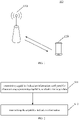
- a data transmission method provided by embodiments of the present disclosure may be applied to a wireless communication system 100 illustrated in FIG. 1 .
- the wireless communication system 100 includes a network device 110 and a terminal 120.
- the terminal 120 is connected with the network device 110 through a wireless resource and transmits and receives data.
- the wireless communication system 100 illustrated in FIG. 1 is only a schematic description.
- the wireless communication system 100 may also include other network devices, such as core network devices, wireless relay devices, wireless backhaul devices, etc., which are not illustrated in FIG. 1 .
- the embodiment of the present disclosure does not limit a quantity of network devices and terminals included in the wireless communication system.
- the wireless communication system of embodiments of the present disclosure is a network for providing a wireless communication function.
- Wireless communication systems may use different communication technologies, such as code division multiple access (CDMA), broadband code division multiple access (WCDMA), time division multiple access (TDMA), frequency division multiple access (FDMA), orthogonal frequency-division multiple access (OFDMA), single carrier frequency division multiple access (SC-FDMA), carrier sense multiple access with collision avoidance.
- CDMA code division multiple access
- WCDMA broadband code division multiple access
- TDMA time division multiple access
- FDMA frequency division multiple access
- OFDMA orthogonal frequency-division multiple access
- SC-FDMA single carrier frequency division multiple access
- the networks may be divided into 2G (generation) network, 3G network, 4G network or future evolution network, such as 5G network, which is also referred to as New Radio (NR), depending on capacity, rate and delay of different networks.
- 5G network which is also referred to as New Radio (NR)
- NR New Radio
- the network device 110 in this disclosure may also be referred to as a wireless access network device.
- the wireless access network device may be a base station, an evolved base station (evolved node B, base station), a home eNode B, and an access point (AP), a wireless relay node, a wireless backhaul node, a transmission point (TP), or a transmission and reception point (TRP) in a wireless fidelity (WIFI) system.
- the wireless access network device may also be a gNB in an NR system, or a component or some devices that forms the base station, etc. It should be understood that there are no limitation on specific technologies and specific device configurations adopted by the network device in the present disclosure.
- the network devices may provide communication coverage for a specific geographic area and may communicate with terminals located within the coverage area (cell).
- the terminal 120 in this disclosure also referred to as a terminal device, a user equipment (UE), a mobile station (MS), a mobile terminal (MT), etc.
- the terminal may be a handheld device, an on-board device, etc. with wireless connection function.
- some examples of terminals are: a smartphone (Mobile Phones), a pocket personal computer (PPC), a palm computer, a personal digital assistants (PDA), a laptop PC, a tablet PC, a wearable device, or an on-board device.
- the terminal device may also be an on-board device. It should be understood that there are no limitation on specific technologies and specific device configurations adopted by the terminal in the present disclosure.
- the terminal 120 communicates with the network device 110, and data transmitted by the terminal 120 to the network device 110 is referred to as uplink data, such as a physical uplink shared channel (PUSCH).
- uplink data such as a physical uplink shared channel (PUSCH).
- Data transmitted by the network device 110 to the terminal 120 is referred to as downlink data, such as a physical downlink Shared channel (PDSCH).
- the terminal 120 is required to process data when transmitting the uplink data or receiving the downlink data.
- the terminal 120 is required to prepare the uplink data when transmitting the uplink data, and to demodulate the downlink data when receiving the downlink data.
- Different capacities for processing the uplink data/downlink data (PUSCH/PDSCH) by the terminal 120 cause different times (in symbols) required for processing PDSCH/PUSCH.
- the processing capability adopted by the terminal when processing the PUSCH/PDSCH is a processing capability enabled towards one carrier, that is, a same processing capability is adopted for different PUSCH/PDSCHs on one carrier.
- different PUSCH/PDSCHs on a single carrier will be applied with different processing capabilities.
- an ultra reliable and low latency communication (URLLC) service is mixed with an enhanced mobile broadband (eMBB) service on one carrier, and the eMBB service generally uses a processing time corresponding to the Cap1 since it does not require ultra low latency, while the URLLC service requires to use a processing time corresponding to the Cap2 in order to meet a low latency characteristic of the URLLC service.
- eMBB enhanced mobile broadband
- the exiting arts do not support scenes where different PDSCH/PUSCHs are applied with different processing capabilities for a UE on one carrier.
- the present disclosure provides a method for determining a processing capacity applicable for target data.
- an applicable processing capability is indicated for target data to be processed, to enable different target data applicable with different processing capabilities.
- Target data in this disclosure may be understood as data to be processed, which may be either uplink data or downlink data. Processing the uplink data using a processing capacity applicable for the target data may be preparing the uplink data. Processing the downlink data using a processing capacity applicable for the target data may be demodulating the downlink data.
- the present disclosure describes a method for determining a processing capacity applicable for target data below.
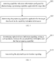
- FIG. 2 is a flow chart illustrating a method for determining a processing capacity applicable for target data according to an exemplary embodiment. As illustrated in FIG. 2 , the method for determining the processing capacity applicable for the target data is applied to a network device, and includes the following block S11 and block S12.
- capability indication information configured for characterizing a processing capability applicable for target data is determined.
- the capability indication information is transmitted.
- the network device determines the capability indication information characterizing the processing capability applicable for the target data, and transmits the capability indication information; such that a terminal received the capability indication information may determine the processing capability applicable for the target data according to the capability indication information.
- FIG. 3 is a flow chart illustrating a method for determining a processing capacity applicable for target data according to an exemplary embodiment. As illustrated in FIG. 3 , the method for determining the processing capacity applicable for the target data is applied to a terminal, and includes the following block S21 and block S22.
- capability indication information configured for characterizing a processing capability applicable for target data is detected.
- the processing capability applicable for the target data is determined based on the capability indication information characterizing the processing capability applicable for the target data.
- the capability indication information characterizes the processing capability applicable for the target data.
- the terminal detects the capability indication information and determines the processing capability for processing the target data based on the detected capability indication information.
- the processing capability is the processing capability applicable for the target data. Therefore, different processing capabilities are respectively determined for different target data processed by the same terminal on one carrier.
- the present disclosure will describe the method for determining the processing capacity applicable for the target data in combination with practical applications.
- a physical layer indication signaling for dynamically scheduled target data, different processing capabilities applicable for the target data are distinguished by a physical layer indication signaling.
- the capability indication information of the present disclosure may be the physical layer indication signaling.
- the capability indication information is preset attribute information of the physical layer indication signaling.
- the preset attribute information has a preset correspondence with one or more of the processing capabilities for processing the target data by the terminal, and different processing capabilities are distinguished through the attribute information of the physical layer instruction signaling.
- the attribute information of the physical layer instruction signaling having the preset correspondence with the processing capability may be understood as indicating the processing capability through the attribute information of the physical layer instruction signaling.
- the correspondence between the attribute information of the physical layer instruction signaling and the processing capability may be either explicit or implicit.
- a processing capability having an explicit correspondence with the preset attribute information of the physical layer indication signaling is referred to as a first processing capability.
- a processing capability having an implicit correspondence with the preset attribute information of the physical layer indication signaling is referred to as a second processing capability.
- the second processing capacity is a processing capacity different from the first processing capacity.
- the processing capability for processing the target data by the terminal includes CAP1 and CAP2.
- the preset attribute information of the physical layer indication signaling has a correspondence with CAP1
- other attribute information of the physical layer indication signaling has an implicit correspondence with CAP2.
- the preset attribute information of the physical layer indication signaling has a correspondence with CAP2
- other attribute information of the physical layer indication signaling has an implicit correspondence with CAP1.
- the first processing capacity is CAP2.
- FIG. 4 is a flow chart illustrating a method for determining a processing capacity applicable for target data according to an exemplary embodiment. As illustrated in FIG. 4 , the method for determining the processing capacity applicable for the target data is applied to the network device, and includes the following block S111 and block S121.
- the physical layer indication signaling is determined.
- the network device determines that the capability indication information is the preset attribute information of the physical layer indication signaling, and sets the correspondence between the preset attribute information and the first processing capability.
- the physical layer instruction signaling is transmitted.
- FIG. 5 is a flow chart illustrating a method for determining a processing capacity applicable for target data according to an exemplary embodiment. As illustrated in FIG. 5 , the method for determining the processing capacity applicable for the target data is applied to the terminal, and includes the following block S211 and block S221.
- the physical layer indication signaling is detected.
- the terminal detects the physical layer indication signaling, and may determine the processing capacity applicable for the target data based on the preset attribute information of the physical layer indication signaling.
- the processing capability applicable for the target data scheduled by the physical layer indication information is the first processing capability.
- the target data scheduled by the physical layer indication information applies with the second processing capability.
- the physical layer indication signaling for the dynamically scheduled target data in the present disclosure may be downlink control information (DCI).
- DCI downlink control information
- first DCI DCI with the preset attribute information and a preset correspondence between the preset attribute information and the first processing capacity
- attribute information of the first DCI is one of a DCI format, a radio network temporary identity (RNTI) used by the DCI, one or more information domains of the DCI, and a control resource set (CORESET) to which a resource occupied by the DCI belongs, and a search spaces to which the resource occupied by the DCI belongs.
- RNTI radio network temporary identity
- CORESET control resource set
- the DCI format of the first DCI characterizes different processing capabilities applicable for data scheduled by the first DCI. For example, when there is a preset correspondence between a certain preset DCI format of the first DCI and the first processing capability, the preset DCI format characterizes that the processing capability applicable for the target data is the first processing capability, and other DCI format other than the preset DCI format characterizes that the processing capability applicable for the target data is the second processing capability. For example, a specific DCI format characterizes that a PDSCH of the Cap 2 is scheduled, and other DCI format characterizes that a PDSCH of the Cap 1 is scheduled.
- the RNTI used in the first DCI characterizes the different processing capabilities applicable for the data scheduled by the first DCI. For example, when there is a preset correspondence between a preset type of RNTI used in the first DCI and the first processing capability, the preset type of RNTI characterizes that the processing capability applicable for the target data is the first processing capability, and other type of RNTI other than the preset type of RNTI characterizes that the processing capability applicable for the target data is the second processing capability. In an example, the RNTI used in the first DCI characterizes whether a processing capacity applicable for the scheduled PDSCH/PUSCH is Cap 1 or Cap 2.
- the processing capacity applicable for the PDSCH/PUSCH scheduled by the first DCI is Cap 2.
- the processing capacity applicable for the PDSCH/PUSCH scheduled by the first DCI is Cap 1.
- MCS modulation and coding scheme
- one information domain or a combination of multiple information domains in the first DCI used in the first DCI characterizes the different processing capabilities applicable for the data scheduled by the first DCI. For example, when there is a preset correspondence between a preset information domain value of a preset information domain in the first DCI and the first processing capability, the preset information domain value of the preset information domain characterizes that the processing capability applicable for the target data is the first processing capability, and other information domain value other than the preset information domain value characterizes that the processing capability applicable for the target data is the second processing capability.
- the foregoing preset state characterizes that the processing capability applicable for the target data is the first processing capability, and other information domain value other than the preset information domain value characterizes that the processing capability applicable for the target data is the second processing capability.
- one information domain in the first DCI characterizes Cap 1 and Cap 2.
- An information domain value of the information domain indicates that whether the processing capacity applicable for the PDSCH/PUSCH scheduled by the first DCI is Cap 1 or Cap 2.
- a combination of several information domains in the first DCI characterizes Cap 1 and Cap 2.
- the combination of the several information domains has a specific information domain value, it represents that the processing capacity applicable for the PDSCH/PUSCH scheduled by the first DCI is Cap 2.
- An information domain value corresponding to other combination represents that the processing capacity applicable for the PDSCH/PUSCH scheduled by the first DCI is Cap 1.
- the CORESET/search space to which the resource occupied by the first DCI belongs characterizes the different processing capabilities applicable for the PDSCH/PUSCH scheduled by the first DCI.
- the network device configures a specific CORESET/search for the terminal in the radio resource control (RRC) layer, and the specific CORESET/search has a preset corresponding relationship with the first processing capability.
- RRC radio resource control
- the processing capacity applicable for the target data scheduled by the first DCI is the second processing capability.
- the processing capacity applicable for the PDSCH/PUSCH scheduled by the first DCI is Cap 2.
- the processing capacity applicable for the PDSCH/PUSCH scheduled by the first DCI is Cap 1.
- the processing capacity applicable for the PDSCH/PUSCH scheduled by the first DCI is indicated by a combination of at least two of the DCI format of the first DCI, the RNTI used in the first DCI, one information domain or a combination of multiple information domains in the first DCI, and CORESET/search space to which the first DCI belongs.
- a processing capacity applicable for the PDSCH/PUSCH scheduled by the first DCI with a specific CORESET resource carrying and a specific DCI format is Cap2, and others are Cap 1.
- the processing capacity applicable for the PDSCH/PUSCH scheduled by the first DCI is Cap2.
- the resource occupied by the first DCI does not belong to the specific CORESET, or the DCI format of the first DCI is not the specific DCI format, it is determined that the processing capacity applicable for the PDSCH/PUSCH scheduled by the first DCI is Cap1.
- the processing capacity applicable for the PDSCH/PUSCH scheduled by the DCI with a specific RNTI and the specific DCI format is Cap2, and others are Cap 1.
- the processing capacity applicable for the PDSCH/PUSCH scheduled by the first DCI is Cap2.
- the RNTI used by the first DCI is not the specific RNTI, or the DCI format of the first DCI is not the specific DCI format, it is determined that the processing capacity applicable for the PDSCH/PUSCH scheduled by the first DCI is Cap1.
- a processing capacity applicable for the PDSCH/PUSCH scheduled by the first DCI with the specific CORESET resource carrying and the specific RNTI is Cap2, and others are Cap 1.
- the processing capacity applicable for the PDSCH/PUSCH scheduled by the first DCI is Cap2.
- the resource occupied by the first DCI does not belong to the specific CORESET, or the RNTI used by the first DCI is not the specific RNTI, it is determined that the processing capacity applicable for the PDSCH/PUSCH scheduled by the first DCI is Cap1.
- a correspondence between the semi-persistent configured resource and the processing capacity is set for the semi-persistent configured resource configured in each cycle period.
- the capability indication information is the semi-persistent configured resource configured by the RRC, and the semi-persistent configured resource with the correspondence with the processing capability indicates the processing capability applicable for the target data.
- the RRC configuring the correspondence between semi-persistent configured resource and the processing capacity is referred to as a first RRC.
- FIG. 6 is a flow chart illustrating a method for determining a processing capacity applicable for target data according to an exemplary embodiment. As illustrated in FIG. 6 , the method for determining the processing capacity applicable for the target data is applied to the network device, and includes the following block S112 and block S122.
- the semi-persistent configured resource configured by the first RRC is determined, and a correspondence between the semi-persistent configured resource and a processing capacity is set.
- the correspondence between the semi-persistent configured resource configured by the first RRC and the processing capacity is transmitted.
- FIG. 7 is a flow chart illustrating a method for determining a processing capacity applicable for target data according to an exemplary embodiment. As illustrated in FIG. 7 , the method for determining the processing capacity applicable for the target data is applied to the terminal, and includes the following block S212 and block S222.
- the semi-persistent configured resource used by the target data is determined.
- a processing capability corresponding to the semi-persistent configured resource is determined as the processing capability applicable for the target data.
- the processing capacity corresponding to the semi-persistent configured resource is configured when the semi-persistent configured resources of PDSCH/PUSCH is directly configured in the RRC.
- the PDSCH/PUSCH uses the above semi-persistent configured resource with the corresponding processing capacity, the PDSCH/PUSCH applies with the processing capacity set by RRC for the semi-persistent configured resource.
- the processing capacity applicable for the target data when there are semi-persistent configured resources of multiple cycles configured in the RRC, a correspondence between a quantity of time domain symbols and the processing capacity, or a correspondence between a bandwidth of frequency domain resource and the processing capacity is set for each cycle of the semi-persistent configured resource.
- the DCI is configured to indicate the quantity of time domain symbols or the bandwidth of frequency domain resource of the semi-persistent configured resource used by the target data, so as to realize indication of the processing capacity applicable for the target data.
- the processing capacity applicable for the target data is CAP2.
- the processing capacity applicable for the target data is CAP1.
- the bandwidth of frequency domain resource is set to be greater than a set bandwidth, the processing capacity applicable for the target data is CAP1.
- DCI indicating the quantity of time domain symbols or the bandwidth of frequency domain resource of the semi-persistent configured resource used by the target data is referred to as second DCI.
- FIG. 8 is a flow chart illustrating a method for determining a processing capacity applicable for target data according to an exemplary embodiment. As illustrated in FIG. 8 , the method for determining the processing capacity applicable for the target data is applied to the network device, and includes the following block S113 and block S123.
- the semi-persistent configured resource is configured in the RRC.
- the correspondence between the quantity of time domain symbols and the processing capacity, or the correspondence between the bandwidth of frequency domain resource and the processing capacity is set.
- the second DCI is transmitted indicating the quantity of time domain symbols or the bandwidth of frequency domain resource of the semi-persistent configured resource used by the target data.
- FIG. 9 is a flow chart illustrating a method for determining a processing capacity applicable for target data according to an exemplary embodiment. As illustrated in FIG. 9 , the method for determining the processing capacity applicable for the target data is applied to the terminal, and includes the following block S213 and block S223.
- the second DCI is obtained, and the quantity of time domain symbols or the bandwidth of frequency domain resource of the semi-persistent configured resource used by the target data is determined according to the second DCI.
- a processing capability corresponding to the quantity of the time domain symbols or the bandwidth of frequency domain resource is determined as the processing capability applicable for the target data.
- FIG. 10 is a flow chart illustrating a method for determining a processing capacity applicable for target data according to an exemplary embodiment. As illustrated in FIG. 10 , the method for determining the processing capacity applicable for the target data is a flow chart of interaction between the terminal and the network device, and includes the following block S31 to block S34.
- the network device determines the capability indication information configured for characterizing the processing capability applicable for the target data.
- the target data is the data dynamically scheduled by the physical layer indication signaling
- the capability indication information is the preset attribute information of the physical layer indication signaling
- the preset attribute information has the preset correspondence with the first processing capability
- the physical layer indication signaling is the first DCI.
- the attribute information in the first DCI having the preset correspondence with the first processing capability includes at least one of the DCI format, the radio network temporary identity used in the DCI, one or more information domains of the DCI, and the control resource set to which the resource occupied by the DCI belongs, and the search spaces to which the resource occupied by the DCI belongs
- the target data is the data transmitted by the semi-persistent configured resource
- the capability indication information includes the semi-persistent configured resource configured by the first RRC signaling
- the semi-persistent configured resource has the preset correspondence with the processing capability
- the target data is the data transmitted by the semi-persistent configured resource
- the capability indication information includes second DCI
- the second DCI is configured to indicate the quantity of time domain symbols or the bandwidth of frequency domain resource of the semi-persistent configured resource used by the target data.
- the quantity of time domain symbols has the preset correspondence with the processing capability, or the bandwidth of frequency domain resource has the preset correspondence with the processing capability.
- the network device transmits the capability indication information characterizing the processing capability applicable for the target data.
- the terminal detects the capability indication information characterizing the processing capability applicable for the target data.
- the terminal determines the processing capability applicable for the target data based on the capability indication information characterizing the processing capability applicable for the target data.
- the terminal determines that target data scheduled by the physical layer indication information applies with the first processing capability in response to the obtained physical layer indication signaling having the preset attribute information.
- the terminal determines the target data scheduled by the physical layer indication information applies with the second processing capability different from the first processing capability in response to the obtained physical layer indication signaling not having the preset attribute information.
- the terminal determines the semi-persistent configured resource used by the target data, and determines the processing capability corresponding to the semi-persistent configured resource as the processing capability applicable for the target data.
- the terminal determines the quantity of the time domain symbols or the bandwidth of frequency domain resource of the semi-persistent configured resource used by the target data according to the second DCI, and determines the processing capability corresponding to the quantity of the time domain symbols or the bandwidth of frequency domain resource as the processing capability applicable for the target data.
- the method for determining the processing capability applicable for the target data may realize determination of different processing capabilities applicable for different target data based on the capability indication information characterizing the processing capability applicable for the target data.
- embodiments of the present disclosure also provide an apparatus for determining a processing capacity applicable for target data.
- the target data applicable processing capability determination device includes include a hardware structure and/or a software module for performing each function.
- the embodiments of the present disclosure may be implemented in a form of hardware or a combination of hardware and computer software. Whether a certain function is executed by the hardware or a manner of the computer software driving the hardware depends on specific applications and design constraint conditions of the technical solution. Those skilled in the art may use different methods for each specific application to implement the described functions, but such implementation should not be considered as going beyond the scope of the technical solution of the embodiments of the present disclosure.
- FIG. 11 is a block diagram illustrating an apparatus 1100 for determining a processing capacity applicable for target data according to an exemplary embodiment.
- the apparatus 1100 for determining the processing capacity applicable for the target data is applied to a terminal.
- the apparatus 1100 for determining the processing capacity applicable for the target data includes a detecting unit 1101 and a processing unit 1102.
- the detecting unit 1101 is configured to detect capability indication information configured for characterizing a processing capability applicable for target data.
- the processing unit 1102 is configured to determine the processing capability applicable for the target data based on the capability indication information.
- the target data is data dynamically scheduled by a physical layer indication signaling
- the capability indication information is preset attribute information of the physical layer indication signaling
- the preset attribute information has a preset correspondence with a first processing capability
- the processing unit 1102 is configured to determine the processing capability applicable for the target data based on the capability indication information in the following operations: in response to the obtained physical layer indication signaling having the preset attribute information, determining that target data scheduled by the physical layer indication information applies with the first processing capability; in response to the obtained physical layer indication signaling not having the preset attribute information, determining that the target data scheduled by the physical layer indication information applies with a second processing capability different from the first processing capability.
- the physical layer indication signaling is first downlink control information (DCI).
- DCI downlink control information
- Attribute information in the first DCI having a preset correspondence with the first processing capability comprises at least one of a DCI format, a radio network temporary identity used in the DCI, one or more information domains of the DCI, and a control resource set to which a resource occupied by the DCI belongs, and a search spaces to which the resource occupied by the DCI belongs.
- the target data is data transmitted by a semi-persistent configured resource
- the capability indication information includes the semi-persistent configured resource configured by a first radio resource control (RRC) signaling
- RRC radio resource control
- the processing unit 1102 is configured to determine the processing capability applicable for the target data based on the capability indication information in the following operations: determining a semi-persistent configured resource used by the target data; determining a processing capability corresponding to the semi-persistent configured resource as the processing capability applicable for the target data.
- the target data is data transmitted by a semi-persistent configured resource
- the capability indication information includes second downlink control information (DCI)
- the second DCI is configured to indicate a quantity of time domain symbols or a bandwidth of frequency domain resource of the semi-persistent configured resource used by the target data.
- the quantity of time domain symbols has a preset correspondence with a processing capability, or the bandwidth of frequency domain resource has a preset correspondence with a processing capability.
- the processing unit 1102 is configured to determine the processing capability applicable for the target data based on the capability indication information in the following operations: determining the quantity of the time domain symbols or the bandwidth of frequency domain resource of the semi-persistent configured resource used by the target data according to the second DCI; determining a processing capability corresponding to the quantity of the time domain symbols or the bandwidth of frequency domain resource as the processing capability applicable for the target data.
- FIG. 12 is a block diagram illustrating an apparatus 1200 for determining a processing capacity applicable for target data according to an exemplary embodiment.
- the apparatus 1200 for determining the processing capacity applicable for the target data is applied to a network device.
- the apparatus 1200 for determining the processing capacity applicable for the target data includes a processing unit 1201 and a transmitting unit 1202.
- the processing unit 1201 is configured to determine capability indication information configured for characterizing a processing capability applicable for target data.
- the transmitting unit 1202 is configured to transmit the capability indication information.
- the target data is data dynamically scheduled by a physical layer indication signaling
- the capability indication information is preset attribute information of the physical layer indication signaling
- the preset attribute information has a preset correspondence with a first processing capability
- the physical layer indication signaling is first DCI.
- Attribute information in the first DCI having a preset correspondence with the first processing capability includes at least one of a DCI format, a radio network temporary identity used in the DCI, one or more information domains of the DCI, and a control resource set to which a resource occupied by the DCI belongs, and a search spaces to which the resource occupied by the DCI belongs.
- the target data is data transmitted by a semi-persistent configured resource
- the capability indication information includes the semi-persistent configured resource configured by a first RRC signaling
- the semi-persistent configured resource has a preset correspondence with a processing capability
- the target data is data transmitted by a semi-persistent configured resource
- the capability indication information includes second DCI
- the second DCI is configured to indicate a quantity of time domain symbols or a bandwidth of frequency domain resource of the semi-persistent configured resource used by the target data.
- the quantity of time domain symbols has a preset correspondence with a processing capability, or the bandwidth of frequency domain resource has a preset correspondence with a processing capability.
- FIG. 13 is a block diagram illustrating an apparatus for determining a processing capacity applicable for target data according to an exemplary embodiment.
- the apparatus 1300 may be a mobile phone, a computer, a digital broadcasting terminal, a messaging device, a game console, a tablet device, a medical equipment, a fitness equipment, a personal digital assistant, etc.
- the apparatus 1300 may include one or more components: a processing component 1302, a memory 1304, a power supply component 1306, a multimedia component 1308, an audio component 1310, an input/output (I/O) interface 1312, a sensor component 1314, and a communication component 1316.
- a processing component 1302 a memory 1304, a power supply component 1306, a multimedia component 1308, an audio component 1310, an input/output (I/O) interface 1312, a sensor component 1314, and a communication component 1316.
- the processing component 1302 generally controls the whole operation of the terminal 1300, such as the operations related to display, phone call, data communication, camera operation and recording operation.
- the processing component 1302 may include one or more processors 1320 to execute instructions, to complete all or part of blocks of the above methods.
- the processing component 1302 may include one or more modules for the convenience of interaction between the processing component 1302 and other components.
- the processing component 1302 may include a multimedia module for the convenience of interaction between the multimedia component 1308 and the processing component 1302.
- the memory 1304 is configured to store all types of data to support the operation of the terminal 1300. Examples of the data include the instructions of any applications or methods operated on terminal 1300, contact data, phone book data, messages, pictures, videos, etc.
- the memory 1304 may be implemented by any type of volatile or non-volatile storage devices or their combination, such as a Static Random Access Memory (SRAM), an Electrically Erasable Programmable Read-Only Memory (EEPROM), an Erasable Programmable Read-Only Memory (EPROM), a Programmable Read-Only Memory (PROM), a Read-Only Memory (ROM), a Magnetic Memory, a Flash Memory, a Magnetic Disk or an Optical Disk.
- SRAM Static Random Access Memory
- EEPROM Electrically Erasable Programmable Read-Only Memory
- EPROM Erasable Programmable Read-Only Memory
- PROM Programmable Read-Only Memory
- ROM Read-Only Memory
- Magnetic Memory a Flash Memory
- Magnetic Disk or an Optical
- the power supply component 1306 may provide power supply for all components of the apparatus 1300.
- the power supply component 1306 may include a power supply management system, one or more power supplies, and other components related to generating, managing and distributing power for the apparatus 1300.
- the multimedia component 1308 includes an output interface screen provided between the apparatus 1300 and the user.
- a screen may include a liquid crystal display (LCD) and a touch panel (TP). If the screen includes a touch panel, the screen may be implemented as a touch screen to receive input signals from the user.
- the touch panel includes one or more touch sensors to sense touching, sliding and gestures on the touch panel. The touch sensor may not only sense the boundary of touching or sliding action, but also detect the duration and pressure related to the touching or sliding operation.
- the multimedia component 1308 includes a front camera and/or a rear camera. When the apparatus 1300 is in operation mode, such as shooting mode or video mode, the front camera or the rear camera may receive the external multimedia data.
- Each front camera and rear camera may be a fixed optical lens system or an optical lens system with focal length and optical zoom capacity.
- the audio component 1310 is configured as an output and/or input signal.
- the audio component 1310 includes a microphone (MIC).
- the microphone is configured to receive external audio signals.
- the audio signals received may be further stored in the memory 1304 or sent via the communication component 1316.
- the audio component 1310 further includes a speaker configured to an output audio signal.
- An I/O interface 1310 provides an interface for the processing component 1302 and the peripheral interface module, in which the peripheral interface module may be a keyboard, click wheel, a button, etc.
- the buttons may include but not limited to a home button, a volume button, a start button and a lock button.
- the sensor component 1314 includes one or more sensors, configured to provide various aspects of status assessment for the apparatus 1300.
- the sensor component 1314 may detect the on/off state of the apparatus 1300 and the relative positioning of the component.
- the component is a display and a keypad of the apparatus 1300.
- the sensor component 1314 may further detect the location change of the apparatus 1300 or one component of the apparatus 1300, the presence or absence of contact between the user and the apparatus 1300, the orientation or acceleration/deceleration of the apparatus 1300, and the temperature change of the apparatus 1300.
- the sensor component 1314 may include a proximity sensor, which is configured to detect the existence of the objects nearby without any physical contact.
- the sensor component 1314 may further include a light sensor such as a CMOS or CCD image sensor, which is configured to use in imaging applications.
- the sensor component 1314 may further include an acceleration transducer, a gyroscope sensor, a magnetic sensor, a pressure sensor or a temperature sensor.
- the communication component 1316 is configured for the convenience of wire or wireless communication between the apparatus 1300 and other devices.
- the apparatus 1300 may access wireless networks based on communication standard, such as Wi-Fi, 2G or 3G, or their combination.
- the communication component 1316 receives broadcast signals or broadcast-related information from an external broadcast management system via a broadcast channel.
- the communication component 1316 further includes a near field communication (NFC) module to facilitate short-range communication.
- NFC near field communication
- the apparatus 1300 may be implemented by one or more application specific integrated circuits(ASIC), digital signal processors (DSP), digital signal processing devices (DSPD), programmable logic devices (PLD), field programmable gate arrays (FPGA), controllers, microcontrollers, microprocessors or other electronics components, which is configured to perform the above method.
- ASIC application specific integrated circuits
- DSP digital signal processors
- DSPD digital signal processing devices
- PLD programmable logic devices
- FPGA field programmable gate arrays
- controllers microcontrollers, microprocessors or other electronics components, which is configured to perform the above method.
- a non-temporary computer readable storage medium which includes instructions, such as the memory 1304 including instructions, in which the instructions may be executed by the processor 1320 of the apparatus 1300 to complete the above methods.
- the non-temporary computer readable storage medium may be a ROM, a random access memory (RAM), a CD-ROM, a magnetic tape, a floppy disk, an optical data storage device, etc.
- FIG. 14 is a block diagram illustrating an apparatus 1400 for determining a processing capacity applicable for target data according to another exemplary embodiment.
- the apparatus 1400 may be provided as a server.
- the apparatus 1400 includes a processing component 1422, which further includes one or more processors and memory resources represented by a memory 1432 for storing instructions executable by the processing component 1422, such as an application program.
- the application stored in the memory 1432 may include one or more modules, each corresponding to a set of instructions.
- the processing component 1422 is configured to execute the instructions to execute the above method.
- the apparatus 1400 may also include a power component 1426 configured to perform power management of the apparatus 1400, a wired or wireless network interface 1450 configured to connect the apparatus 1400 to the network, and an input/output (I/O) interface 1458.
- the apparatus 1400 may operate based on an operating system stored in the memory 1432, such as Windows ServerTM, Mac OS XTM, UnixTM, Linux TM, FreeBSDTM, or the like.
- a non-temporary computer-readable storage medium including instructions such as a memory 1432 including instructions, which may be executed by the processing component 1422 of apparatus 1400 to complete the above method, is also provided.
- the non-temporary computer-readable storage medium may be a ROM, a random access memory (RAM), a CD-ROM, a magnetic tape, a floppy disk, an optical data storage device, etc.
Landscapes
- Engineering & Computer Science (AREA)
- Computer Networks & Wireless Communication (AREA)
- Signal Processing (AREA)
- Databases & Information Systems (AREA)
- Mobile Radio Communication Systems (AREA)
Applications Claiming Priority (1)
| Application Number | Priority Date | Filing Date | Title |
|---|---|---|---|
| PCT/CN2019/096236 WO2021007788A1 (fr) | 2019-07-16 | 2019-07-16 | Procédé pour déterminer une capacité de traitement appropriée pour des données cibles, appareil et support d'enregistrement |
Publications (2)
| Publication Number | Publication Date |
|---|---|
| EP4002931A1 true EP4002931A1 (fr) | 2022-05-25 |
| EP4002931A4 EP4002931A4 (fr) | 2023-03-08 |
Family
ID=74210142
Family Applications (1)
| Application Number | Title | Priority Date | Filing Date |
|---|---|---|---|
| EP19937448.9A Pending EP4002931A4 (fr) | 2019-07-16 | 2019-07-16 | Procédé pour déterminer une capacité de traitement appropriée pour des données cibles, appareil et support d'enregistrement |
Country Status (4)
| Country | Link |
|---|---|
| US (1) | US12096462B2 (fr) |
| EP (1) | EP4002931A4 (fr) |
| CN (1) | CN112534912B (fr) |
| WO (1) | WO2021007788A1 (fr) |
Families Citing this family (1)
| Publication number | Priority date | Publication date | Assignee | Title |
|---|---|---|---|---|
| CN116437459A (zh) * | 2021-12-29 | 2023-07-14 | 维沃移动通信有限公司 | 数据处理方法、装置、通信设备及可读存储介质 |
Family Cites Families (18)
| Publication number | Priority date | Publication date | Assignee | Title |
|---|---|---|---|---|
| US8750903B1 (en) | 2012-02-28 | 2014-06-10 | CellAntenna Corporation | Cell phone control and localization for restricted facilities |
| CN108111291B (zh) * | 2013-01-25 | 2021-08-20 | 华为技术有限公司 | 解调参考信号传输装置和计算机可读存储介质 |
| CN104010382B (zh) * | 2013-02-25 | 2019-02-01 | 中兴通讯股份有限公司 | 数据传输方法、装置及系统 |
| US10314077B2 (en) * | 2013-05-20 | 2019-06-04 | Qualcomm Incorporated | Gating scheme for wireless communication over unlicensed spectrum |
| CN104852778B (zh) * | 2014-02-18 | 2020-03-13 | 中兴通讯股份有限公司 | 一种开销信息传输方法,基站、终端和系统 |
| CN106793097B (zh) * | 2016-04-01 | 2019-12-03 | 展讯通信(上海)有限公司 | 用户设备、网络侧设备及用户设备的控制方法 |
| EP3487238B1 (fr) * | 2016-08-12 | 2023-07-26 | Huawei Technologies Co., Ltd. | Procédé de transmission de données |
| CN108271259B (zh) * | 2016-12-30 | 2023-10-24 | 华为技术有限公司 | 控制信道的资源指示方法、用户设备和网络设备 |
| CN111555840B (zh) * | 2017-05-05 | 2024-10-15 | 华为技术有限公司 | 一种信息传输的方法及装置 |
| WO2019048932A2 (fr) * | 2017-09-11 | 2019-03-14 | Lenovo (Singapore) Pte. Ltd. | Procédés et dispositifs pour la transmission d'informations de capacité de dispositif |
| RU2762158C2 (ru) * | 2017-10-19 | 2021-12-16 | Гуандун Оппо Мобайл Телекоммьюникейшнз Корп., Лтд. | Способ и аппаратура для управления функциональной возможностью ue ограниченного пользования и компьютерный носитель данных |
| US10764896B2 (en) * | 2017-11-08 | 2020-09-01 | Samsung Electronics Co., Ltd. | Method and apparatus for beam management in the unlicensed spectrum |
| EP3716704A4 (fr) * | 2017-12-12 | 2020-11-11 | Huawei Technologies Co., Ltd. | Procédé et appareil de transmission de données |
| CN110012541B (zh) * | 2018-01-05 | 2023-05-09 | 中国移动通信有限公司研究院 | 终端能力等级调整方法、网络侧设备及终端 |
| US11025456B2 (en) * | 2018-01-12 | 2021-06-01 | Apple Inc. | Time domain resource allocation for mobile communication |
| CN110753341A (zh) * | 2018-07-23 | 2020-02-04 | 华为技术有限公司 | 一种资源配置方法及装置 |
| EP3860177A1 (fr) * | 2018-09-28 | 2021-08-04 | NTT DoCoMo, Inc. | Équipement utilisateur |
| WO2020222275A1 (fr) * | 2019-05-02 | 2020-11-05 | 株式会社Nttドコモ | Terminal utilisateur et procédé de communication sans fil |
-
2019
- 2019-07-16 EP EP19937448.9A patent/EP4002931A4/fr active Pending
- 2019-07-16 CN CN201980001359.1A patent/CN112534912B/zh active Active
- 2019-07-16 WO PCT/CN2019/096236 patent/WO2021007788A1/fr not_active Ceased
- 2019-07-16 US US17/627,034 patent/US12096462B2/en active Active
Also Published As
| Publication number | Publication date |
|---|---|
| WO2021007788A1 (fr) | 2021-01-21 |
| US12096462B2 (en) | 2024-09-17 |
| US20220256528A1 (en) | 2022-08-11 |
| EP4002931A4 (fr) | 2023-03-08 |
| CN112534912A (zh) | 2021-03-19 |
| CN112534912B (zh) | 2023-10-03 |
Similar Documents
| Publication | Publication Date | Title |
|---|---|---|
| EP4175338A1 (fr) | Procédé de traitement de communication, appareil de traitement de communication et support d'enregistrement | |
| CN111344994A (zh) | 数据传输方法及数据传输装置 | |
| CN116471667B (zh) | 波束失败请求资源分配方法、装置及存储介质 | |
| WO2022141074A1 (fr) | Procédé d'indication de faisceau, appareil d'indication de faisceau, et support de stockage | |
| CN113632581B (zh) | 随机接入方法、装置及存储介质 | |
| US11937180B2 (en) | Carrier activation method, device, apparatus, system, and storage medium | |
| CN113796110B (zh) | 一种执行小数据包传输和确定随机接入消息传输方式的方法、装置、设备及存储介质 | |
| US12563521B2 (en) | Parameter configuration method, parameter configuration apparatus, and storage medium | |
| CN111727654A (zh) | 数据传输方法、数据传输装置及存储介质 | |
| CN116137957A (zh) | 一种调度方法、调度装置及存储介质 | |
| EP4408091A1 (fr) | Procédé et appareil de détermination de partie de largeur de bande initiale et support de stockage | |
| CN116438868A (zh) | 一种通信方法、装置及存储介质 | |
| CN115997366A (zh) | 传输配置指示状态的确定方法、装置及存储介质 | |
| CN118400809A (zh) | 一种消息配置方法、消息配置装置及存储介质 | |
| US12096462B2 (en) | Method and apparatus for determining processing capacity applicable for target data | |
| KR20230125831A (ko) | 랜덤 액세스 파라미터 설정 방법, 장치 및 저장 매체 | |
| CN112689965A (zh) | 一种传输方法、传输装置及存储介质 | |
| EP4668963A1 (fr) | Procédé et dispositif de détermination d'état d'indication de configuration de transmission, procédé et dispositif de configuration d'état d'indication de configuration de transmission, et support de stockage | |
| CN114667764B (zh) | 带宽部分切换方法及装置、通信设备及存储介质 | |
| CN111527723B (zh) | 控制信令检测方法、控制信令检测装置及存储介质 | |
| CN114762428A (zh) | 一种数据传输方法、数据传输装置及存储介质 | |
| EP4642124A1 (fr) | Procédé et appareil de détermination d'état d'indicateur de configuration de transmission, et support de stockage | |
| US12526078B2 (en) | Transmission configuration method, transmission configuration apparatus and storage medium | |
| EP4668964A1 (fr) | Procédé et appareil de détermination d'état d'indication de configuration de transmission, support de stockage | |
| US20240205946A1 (en) | Sidelink communication method and apparatus, and storage medium |
Legal Events
| Date | Code | Title | Description |
|---|---|---|---|
| STAA | Information on the status of an ep patent application or granted ep patent |
Free format text: STATUS: THE INTERNATIONAL PUBLICATION HAS BEEN MADE |
|
| PUAI | Public reference made under article 153(3) epc to a published international application that has entered the european phase |
Free format text: ORIGINAL CODE: 0009012 |
|
| STAA | Information on the status of an ep patent application or granted ep patent |
Free format text: STATUS: REQUEST FOR EXAMINATION WAS MADE |
|
| 17P | Request for examination filed |
Effective date: 20220215 |
|
| AK | Designated contracting states |
Kind code of ref document: A1 Designated state(s): AL AT BE BG CH CY CZ DE DK EE ES FI FR GB GR HR HU IE IS IT LI LT LU LV MC MK MT NL NO PL PT RO RS SE SI SK SM TR |
|
| DAV | Request for validation of the european patent (deleted) | ||
| DAX | Request for extension of the european patent (deleted) | ||
| A4 | Supplementary search report drawn up and despatched |
Effective date: 20230206 |
|
| RIC1 | Information provided on ipc code assigned before grant |
Ipc: H04W 8/26 20090101ALN20230131BHEP Ipc: H04W 8/22 20090101ALI20230131BHEP Ipc: H04W 72/04 20090101AFI20230131BHEP |
|
| STAA | Information on the status of an ep patent application or granted ep patent |
Free format text: STATUS: EXAMINATION IS IN PROGRESS |
|
| 17Q | First examination report despatched |
Effective date: 20250221 |