EP4002953A1 - Procédé et appareil d'acquisition d'informations de système et de radiomessagerie par l'intermédiaire d'un relais équipement utilisateur-réseau dans un système de communication sans fil - Google Patents
Procédé et appareil d'acquisition d'informations de système et de radiomessagerie par l'intermédiaire d'un relais équipement utilisateur-réseau dans un système de communication sans fil Download PDFInfo
- Publication number
- EP4002953A1 EP4002953A1 EP21204112.3A EP21204112A EP4002953A1 EP 4002953 A1 EP4002953 A1 EP 4002953A1 EP 21204112 A EP21204112 A EP 21204112A EP 4002953 A1 EP4002953 A1 EP 4002953A1
- Authority
- EP
- European Patent Office
- Prior art keywords
- relay
- remote
- rrc
- network
- message
- Prior art date
- Legal status (The legal status is an assumption and is not a legal conclusion. Google has not performed a legal analysis and makes no representation as to the accuracy of the status listed.)
- Pending
Links
- 238000000034 method Methods 0.000 title claims abstract description 155
- 238000004891 communication Methods 0.000 title claims abstract description 109
- 230000004044 response Effects 0.000 claims description 15
- 239000000725 suspension Substances 0.000 claims description 11
- 230000011664 signaling Effects 0.000 description 38
- 230000006978 adaptation Effects 0.000 description 36
- 238000013507 mapping Methods 0.000 description 33
- 101150096310 SIB1 gene Proteins 0.000 description 28
- 230000005540 biological transmission Effects 0.000 description 25
- 108091005487 SCARB1 Proteins 0.000 description 24
- 102100037118 Scavenger receptor class B member 1 Human genes 0.000 description 24
- 238000012544 monitoring process Methods 0.000 description 18
- 238000005259 measurement Methods 0.000 description 14
- 238000007726 management method Methods 0.000 description 13
- 230000009471 action Effects 0.000 description 11
- 238000013475 authorization Methods 0.000 description 11
- 230000000977 initiatory effect Effects 0.000 description 11
- 230000008859 change Effects 0.000 description 10
- 238000012986 modification Methods 0.000 description 10
- 230000004048 modification Effects 0.000 description 10
- 101150014328 RAN2 gene Proteins 0.000 description 9
- 230000000737 periodic effect Effects 0.000 description 9
- CSRZQMIRAZTJOY-UHFFFAOYSA-N trimethylsilyl iodide Substances C[Si](C)(C)I CSRZQMIRAZTJOY-UHFFFAOYSA-N 0.000 description 9
- 238000013461 design Methods 0.000 description 8
- 230000007246 mechanism Effects 0.000 description 8
- 101001055444 Homo sapiens Mediator of RNA polymerase II transcription subunit 20 Proteins 0.000 description 7
- 102100026165 Mediator of RNA polymerase II transcription subunit 20 Human genes 0.000 description 7
- 238000010586 diagram Methods 0.000 description 7
- 230000008569 process Effects 0.000 description 7
- 230000006399 behavior Effects 0.000 description 6
- 230000001960 triggered effect Effects 0.000 description 5
- 101100533725 Mus musculus Smr3a gene Proteins 0.000 description 4
- 101100117569 Oryza sativa subsp. japonica DRB6 gene Proteins 0.000 description 4
- 238000005516 engineering process Methods 0.000 description 4
- 238000012546 transfer Methods 0.000 description 4
- 230000001143 conditioned effect Effects 0.000 description 3
- 230000006870 function Effects 0.000 description 3
- 239000011159 matrix material Substances 0.000 description 3
- 238000012545 processing Methods 0.000 description 3
- 102100039292 Cbp/p300-interacting transactivator 1 Human genes 0.000 description 2
- 101150090033 DRB2 gene Proteins 0.000 description 2
- 101150034979 DRB3 gene Proteins 0.000 description 2
- 101150082328 DRB5 gene Proteins 0.000 description 2
- 101000888413 Homo sapiens Cbp/p300-interacting transactivator 1 Proteins 0.000 description 2
- 101001100327 Homo sapiens RNA-binding protein 45 Proteins 0.000 description 2
- 101100274486 Mus musculus Cited2 gene Proteins 0.000 description 2
- 101100278514 Oryza sativa subsp. japonica DRB2 gene Proteins 0.000 description 2
- 101100117565 Oryza sativa subsp. japonica DRB4 gene Proteins 0.000 description 2
- 101100117568 Oryza sativa subsp. japonica DRB5 gene Proteins 0.000 description 2
- 208000004605 Persistent Truncus Arteriosus Diseases 0.000 description 2
- 102100038823 RNA-binding protein 45 Human genes 0.000 description 2
- 101150096622 Smr2 gene Proteins 0.000 description 2
- 208000037258 Truncus arteriosus Diseases 0.000 description 2
- 238000004590 computer program Methods 0.000 description 2
- 230000007774 longterm Effects 0.000 description 2
- 238000010295 mobile communication Methods 0.000 description 2
- 230000003287 optical effect Effects 0.000 description 2
- 238000005457 optimization Methods 0.000 description 2
- 239000002245 particle Substances 0.000 description 2
- 230000007704 transition Effects 0.000 description 2
- 238000010200 validation analysis Methods 0.000 description 2
- AKIJONGZTGVCPH-UHFFFAOYSA-N 4-phenoxypyridine-2,6-diamine Chemical compound NC1=NC(N)=CC(OC=2C=CC=CC=2)=C1 AKIJONGZTGVCPH-UHFFFAOYSA-N 0.000 description 1
- 101100396152 Arabidopsis thaliana IAA19 gene Proteins 0.000 description 1
- 101100150275 Caenorhabditis elegans srb-3 gene Proteins 0.000 description 1
- 101150039363 SIB2 gene Proteins 0.000 description 1
- 238000004458 analytical method Methods 0.000 description 1
- 238000013459 approach Methods 0.000 description 1
- 230000015556 catabolic process Effects 0.000 description 1
- 230000000295 complement effect Effects 0.000 description 1
- 230000001419 dependent effect Effects 0.000 description 1
- 238000001514 detection method Methods 0.000 description 1
- 238000001585 disappearance potential spectroscopy Methods 0.000 description 1
- 230000009977 dual effect Effects 0.000 description 1
- 238000011156 evaluation Methods 0.000 description 1
- 230000003993 interaction Effects 0.000 description 1
- 239000000203 mixture Substances 0.000 description 1
- 230000008520 organization Effects 0.000 description 1
- 239000005022 packaging material Substances 0.000 description 1
- ZRBFEDMQRDRUDG-UHFFFAOYSA-N silicon hexaboride Chemical compound B12B3[Si]45B3B2B4B51 ZRBFEDMQRDRUDG-UHFFFAOYSA-N 0.000 description 1
- 238000000638 solvent extraction Methods 0.000 description 1
- 238000001228 spectrum Methods 0.000 description 1
Images


Classifications
-
- H—ELECTRICITY
- H04—ELECTRIC COMMUNICATION TECHNIQUE
- H04W—WIRELESS COMMUNICATION NETWORKS
- H04W72/00—Local resource management
- H04W72/20—Control channels or signalling for resource management
- H04W72/23—Control channels or signalling for resource management in the downlink direction of a wireless link, i.e. towards a terminal
-
- H—ELECTRICITY
- H04—ELECTRIC COMMUNICATION TECHNIQUE
- H04W—WIRELESS COMMUNICATION NETWORKS
- H04W40/00—Communication routing or communication path finding
- H04W40/02—Communication route or path selection, e.g. power-based or shortest path routing
- H04W40/22—Communication route or path selection, e.g. power-based or shortest path routing using selective relaying for reaching a BTS [Base Transceiver Station] or an access point
-
- H—ELECTRICITY
- H04—ELECTRIC COMMUNICATION TECHNIQUE
- H04W—WIRELESS COMMUNICATION NETWORKS
- H04W12/00—Security arrangements; Authentication; Protecting privacy or anonymity
- H04W12/06—Authentication
-
- H—ELECTRICITY
- H04—ELECTRIC COMMUNICATION TECHNIQUE
- H04W—WIRELESS COMMUNICATION NETWORKS
- H04W12/00—Security arrangements; Authentication; Protecting privacy or anonymity
- H04W12/10—Integrity
-
- H—ELECTRICITY
- H04—ELECTRIC COMMUNICATION TECHNIQUE
- H04W—WIRELESS COMMUNICATION NETWORKS
- H04W12/00—Security arrangements; Authentication; Protecting privacy or anonymity
- H04W12/60—Context-dependent security
- H04W12/69—Identity-dependent
-
- H—ELECTRICITY
- H04—ELECTRIC COMMUNICATION TECHNIQUE
- H04W—WIRELESS COMMUNICATION NETWORKS
- H04W76/00—Connection management
- H04W76/10—Connection setup
- H04W76/11—Allocation or use of connection identifiers
-
- H—ELECTRICITY
- H04—ELECTRIC COMMUNICATION TECHNIQUE
- H04W—WIRELESS COMMUNICATION NETWORKS
- H04W76/00—Connection management
- H04W76/10—Connection setup
- H04W76/14—Direct-mode setup
-
- H—ELECTRICITY
- H04—ELECTRIC COMMUNICATION TECHNIQUE
- H04W—WIRELESS COMMUNICATION NETWORKS
- H04W76/00—Connection management
- H04W76/20—Manipulation of established connections
- H04W76/27—Transitions between radio resource control [RRC] states
-
- H—ELECTRICITY
- H04—ELECTRIC COMMUNICATION TECHNIQUE
- H04W—WIRELESS COMMUNICATION NETWORKS
- H04W76/00—Connection management
- H04W76/30—Connection release
-
- H—ELECTRICITY
- H04—ELECTRIC COMMUNICATION TECHNIQUE
- H04W—WIRELESS COMMUNICATION NETWORKS
- H04W88/00—Devices specially adapted for wireless communication networks, e.g. terminals, base stations or access point devices
- H04W88/02—Terminal devices
-
- H—ELECTRICITY
- H04—ELECTRIC COMMUNICATION TECHNIQUE
- H04W—WIRELESS COMMUNICATION NETWORKS
- H04W88/00—Devices specially adapted for wireless communication networks, e.g. terminals, base stations or access point devices
- H04W88/02—Terminal devices
- H04W88/04—Terminal devices adapted for relaying to or from another terminal or user
Definitions
- This disclosure generally relates to wireless communication networks, and more particularly, to a method and apparatus for acquiring system information and paging via UE-to-network relay in a wireless communication system.
- IP Internet Protocol
- An exemplary network structure is an Evolved Universal Terrestrial Radio Access Network (E-UTRAN).
- E-UTRAN Evolved Universal Terrestrial Radio Access Network
- the E-UTRAN system can provide high data throughput in order to realize the above-noted voice over IP and multimedia services.
- a new radio technology for the next generation e.g., 5G
- 5G next generation
- changes to the current body of 3GPP standard are currently being submitted and considered to evolve and finalize the 3GPP standard.
- the method includes the remote UE connecting with a relay UE.
- the method also includes the remote UE connecting with a first network node via the relay UE.
- the method further includes the remote UE receiving a first Radio Resource Control (RRC) message from the first network node via the relay UE, wherein the first RRC message includes a Cell Radio Network Temporary Identifier (C-RNTI) of the remote UE used for constructing authentication information.
- RRC Radio Resource Control
- C-RNTI Cell Radio Network Temporary Identifier
- Wireless communication systems are widely deployed to provide various types of communication such as voice, data, and so on. These systems may be based on code division multiple access (CDMA), time division multiple access (TDMA), orthogonal frequency division multiple access (OFDMA), 3GPP LTE (Long Term Evolution) wireless access, 3GPP LTE-A or LTE-Advanced (Long Term Evolution Advanced), 3GPP2 UMB (Ultra Mobile Broadband), WiMax, 3GPP NR (New Radio), or some other modulation techniques.
- CDMA code division multiple access
- TDMA time division multiple access
- OFDMA orthogonal frequency division multiple access
- 3GPP LTE Long Term Evolution
- 3GPP LTE-A or LTE-Advanced Long Term Evolution Advanced
- 3GPP2 UMB User Mobile Broadband
- WiMax Wireless Broadband
- 3GPP NR New Radio
- the exemplary wireless communication systems and devices described below may be designed to support one or more standards such as the standard offered by a consortium named "3rd Generation Partnership Project” referred to herein as 3GPP, including: TS 38.331 V16.2.0, “NR; Radio Resource Control (RRC) protocol specification (Release 16) "; TS 38.300 V16.1.0, “NR; NR and NG-RAN Overall Description; Stage 2 (Release 16) “; TR 23.752 V0.5.1, "Study on system enhancement for Proximity based Services (ProSe) in the 5G System (5GS) (Release 17) "; R2-2008922, “On-demand SI Delivery for Remote UE ", CATT; 3GPP RAN2#112e Chairman's notes; TS 23.502 V16.4.0, “Procedures for the 5G System; Stage 2 (Release 16) “; and TR 38.836 V0.1.1, “Study on NR sidelink relay; (Release 17) ";
- FIG. 1 shows a multiple access wireless communication system according to one embodiment of the invention.
- An access network 100 includes multiple antenna groups, one including 104 and 106, another including 108 and 110, and an additional including 112 and 114. In FIG. 1 , only two antennas are shown for each antenna group, however, more or fewer antennas may be utilized for each antenna group.
- Access terminal 116 is in communication with antennas 112 and 114, where antennas 112 and 114 transmit information to access terminal 116 over forward link 120 and receive information from access terminal 116 over reverse link 118.
- Access terminal (AT) 122 is in communication with antennas 106 and 108, where antennas 106 and 108 transmit information to access terminal (AT) 122 over forward link 126 and receive information from access terminal (AT) 122 over reverse link 124.
- communication links 118, 120, 124 and 126 may use different frequency for communication.
- forward link 120 may use a different frequency then that used by reverse link 118.
- antenna groups each are designed to communicate to access terminals in a sector of the areas covered by access network 100.
- the transmitting antennas of access network 100 may utilize beamforming in order to improve the signal-to-noise ratio of forward links for the different access terminals 116 and 122. Also, an access network using beamforming to transmit to access terminals scattered randomly through its coverage causes less interference to access terminals in neighboring cells than an access network transmitting through a single antenna to all its access terminals.
- An access network may be a fixed station or base station used for communicating with the terminals and may also be referred to as an access point, a Node B, a base station, an enhanced base station, an evolved Node B (eNB), a network node, a network, or some other terminology.
- An access terminal may also be called user equipment (UE), a wireless communication device, terminal, access terminal or some other terminology.
- FIG. 2 is a simplified block diagram of an embodiment of a transmitter system 210 (also known as the access network) and a receiver system 250 (also known as access terminal (AT) or user equipment (UE)) in a MIMO system 200.
- a transmitter system 210 also known as the access network
- a receiver system 250 also known as access terminal (AT) or user equipment (UE)
- traffic data for a number of data streams is provided from a data source 212 to a transmit (TX) data processor 214.
- TX transmit
- each data stream is transmitted over a respective transmit antenna.
- TX data processor 214 formats, codes, and interleaves the traffic data for each data stream based on a particular coding scheme selected for that data stream to provide coded data.
- the coded data for each data stream may be multiplexed with pilot data using OFDM techniques.
- the pilot data is typically a known data pattern that is processed in a known manner and may be used at the receiver system to estimate the channel response.
- the multiplexed pilot and coded data for each data stream is then modulated (i.e., symbol mapped) based on a particular modulation scheme (e.g., BPSK, QPSK, M-PSK, or M-QAM) selected for that data stream to provide modulation symbols.
- a particular modulation scheme e.g., BPSK, QPSK, M-PSK, or M-QAM
- the data rate, coding, and modulation for each data stream may be determined by instructions performed by processor 230.
- TX MIMO processor 220 may further process the modulation symbols (e.g., for OFDM).
- TX MIMO processor 220 then provides N T modulation symbol streams to N T transmitters (TMTR) 222a through 222t.
- TMTR TX MIMO processor 220 applies beamforming weights to the symbols of the data streams and to the antenna from which the symbol is being transmitted.
- Each transmitter 222 receives and processes a respective symbol stream to provide one or more analog signals, and further conditions (e.g., amplifies, filters, and upconverts) the analog signals to provide a modulated signal suitable for transmission over the MIMO channel.
- N T modulated signals from transmitters 222a through 222t are then transmitted from N T antennas 224a through 224t, respectively.
- the transmitted modulated signals are received by N R antennas 252a through 252r and the received signal from each antenna 252 is provided to a respective receiver (RCVR) 254a through 254r.
- Each receiver 254 conditions (e.g., filters, amplifies, and downconverts) a respective received signal, digitizes the conditioned signal to provide samples, and further processes the samples to provide a corresponding "received" symbol stream.
- An RX data processor 260 then receives and processes the N R received symbol streams from N R receivers 254 based on a particular receiver processing technique to provide N T "detected" symbol streams.
- the RX data processor 260 then demodulates, deinterleaves, and decodes each detected symbol stream to recover the traffic data for the data stream.
- the processing by RX data processor 260 is complementary to that performed by TX MIMO processor 220 and TX data processor 214 at transmitter system 210.
- a processor 270 periodically determines which pre-coding matrix to use (discussed below). Processor 270 formulates a reverse link message comprising a matrix index portion and a rank value portion.
- the reverse link message may comprise various types of information regarding the communication link and/or the received data stream.
- the reverse link message is then processed by a TX data processor 238, which also receives traffic data for a number of data streams from a data source 236, modulated by a modulator 280, conditioned by transmitters 254a through 254r, and transmitted back to transmitter system 210.
- the modulated signals from receiver system 250 are received by antennas 224, conditioned by receivers 222, demodulated by a demodulator 240, and processed by a RX data processor 242 to extract the reserve link message transmitted by the receiver system 250.
- Processor 230 determines which pre-coding matrix to use for determining the beamforming weights then processes the extracted message.
- FIG. 3 shows an alternative simplified functional block diagram of a communication device according to one embodiment of the invention.
- the communication device 300 in a wireless communication system can be utilized for realizing the UEs (or ATs) 116 and 122 in FIG. 1 or the base station (or AN) 100 in FIG. 1 , and the wireless communications system is preferably the NR system.
- the communication device 300 may include an input device 302, an output device 304, a control circuit 306, a central processing unit (CPU) 308, a memory 310, a program code 312, and a transceiver 314.
- the control circuit 306 executes the program code 312 in the memory 310 through the CPU 308, thereby controlling an operation of the communications device 300.
- the communications device 300 can receive signals input by a user through the input device 302, such as a keyboard or keypad, and can output images and sounds through the output device 304, such as a monitor or speakers.
- the transceiver 314 is used to receive and transmit wireless signals, delivering received signals to the control circuit 306, and outputting signals generated by the control circuit 306 wirelessly.
- the communication device 300 in a wireless communication system can also be utilized for realizing the AN 100 in FIG. 1 .
- FIG. 4 is a simplified block diagram of the program code 312 shown in FIG. 3 in accordance with one embodiment of the invention.
- the program code 312 includes an application layer 400, a Layer 3 portion 402, and a Layer 2 portion 404, and is coupled to a Layer 1 portion 406.
- the Layer 3 portion 402 generally performs radio resource control.
- the Layer 2 portion 404 generally performs link control.
- the Layer 1 portion 406 generally performs physical connections.
- 3GPP TS 38.331 introduces the following:
- SI System Information
- the UE applies the SI acquisition procedure to acquire the AS, NAS- and positioning assistance data information.
- the procedure applies to UEs in RRC_IDLE, in RRC_INACTIVE and in RRC_CONNECTED.
- the UE in RRC_IDLE and RRC_INACTIVE shall ensure having a valid version of (at least) the MIB, SIB1 through SIB4, SIB5 (if the UE supports E-UTRA), SIB11 (if the UE is configured for idle/inactive measurements), SIB12 (if UE is capable of NR sidelink communication and is configured by upper layers to receive or transmit NR sidelink communication), and SIB13, SIB14 (if UE is capable of V2X sidelink communication and is configured by upper layers to receive or transmit V2X sidelink communication).
- the UE shall perform the following actions upon reception of the RRCReconfiguration, or upon execution of the conditional reconfiguration (CHO or CPC):
- the network initiates the RRC connection release procedure to transit a UE in RRC_CONNECTED to RRC_IDLE; or to transit a UE in RRC_CONNECTED to RRC_INACTIVE only if SRB2 and at least one DRB or, for IAB, SRB2, is setup in RRC_CONNECTED; or to transit a UE in RRC_INACTIVE back to RRC_INACTIVE when the UE tries to resume; or to transit a UE in RRC_INACTIVE to RRC_IDLE when the UE tries to resume.
- the procedure can also be used to release and redirect a UE to another frequency.
- the UE shall:
- the purpose of this procedure is to resume a suspended RRC connection, including resuming SRB(s) and DRB(s) or perform an RNA update.
- the UE initiates the procedure when upper layers or AS (when responding to RAN paging, upon triggering RNA updates while the UE is in RRC_INACTIVE, or for sidelink communication as specified in sub-clause 5.3.13.1a) requests the resume of a suspended RRC connection.
- the UE shall ensure having valid and up to date essential system information as specified in clause 5.2.2.2 before initiating this procedure.
- the UE Upon initiation of the procedure, the UE shall:
- the UE shall set the contents of RRCResumeRequest or RRCResumeRequestl message as follows:
- the UE shall continue cell re-selection related measurements as well as cell re-selection evaluation. If the conditions for cell re-selection are fulfilled, the UE shall perform cell re-selection as specified in 5.3.13.6.
- the UE In RRC_INACTIVE state, the UE shall:
- the UE in RRC_INACTIVE state fails to find a suitable cell and camps on the acceptable cell to obtain limited service as defined in TS 38.304 [20], the UE shall: 1> perform the actions upon going to RRC_IDLE as specified in 5.3.11 with release cause 'other'.
- the UE shall: 1> perform the actions as specified in 5.3.8.
- the UL-CCCH-Message class is the set of 48-bits RRC messages that may be sent from the UE to the Network on the uplink CCCH logical channel.
- the UL-DCCH-Message class is the set of RRC messages that may be sent from the UE to the network on the uplink DCCH logical channel.
- the BCCH-BCH-Message class is the set of RRC messages that may be sent from the network to the UE via BCH on the BCCH logical channel.
- the BCCH-DL-SCH-Message class is the set of RRC messages that may be sent from the network to the UE via DL-SCH on the BCCH logical channel.
- the RRCResumeRequest message is used to request the resumption of a suspended RRC connection or perform an RNA update.
- RRCResumeRequest-IEs field descriptions resumeCause Provides the resume cause for the RRC connection resume request as provided by the upper layers or RRC.
- the network is not expected to reject an RRCResumeRequest due to unknown cause value being used by the UE.
- resumeldentity UE identity to facilitate UE context retrieval at gNB.
- resumeMAC-I Authentication token to facilitate UE authentication at gNB. The 16 least significant bits of the MAC-I calculated using the AS security configuration as specified in 5.3.13.3.
- the RRCResumeRequestl message is used to request the resumption of a suspended RRC connection or perform an RNA update.
- RRCResumeRequestl-IEs field descriptions resumeCause Provides the resume cause for the RRCResumeRequest1 as provided by the upper layers or RRC.
- a gNB is not expected to reject an RRCResumeRequest1 due to unknown cause value being used by the UE.
- resumeldentity UE identity to facilitate UE context retrieval at gNB.
- resumeMAC-I Authentication token to facilitate UE authentication at gNB. The 16 least significant bits of the MAC-I calculated using the AS security configuration as specified in 5.3.13.3.
- the RRCResume message is used to resume the suspended RRC connection.
- the RRCResumeComplete message is used to confirm the successful completion of an RRC connection resumption.
- the RRCRelease message is used to command the release of an RRC connection or the suspension of the RRC connection.
- suspendConfig Indicates configuration for the RRC_INACTIVE state.
- the network does not configure suspendConfig when the network redirect the UE to an inter-RAT carrier frequency or if the UE is configured with a DAPS bearer.
- ran-PagingCycle Refers to the UE specific cycle for RAN-initiated paging. Value rf32 corresponds to 32 radio frames, value rf64 corresponds to 64 radio frames and so on. t380 Refers to the timer that triggers the periodic RNAU procedure in UE. Value min5 corresponds to 5 minutes, value min10 corresponds to 10 minutes and so on.
- the RRCReconfiguration message is the command to modify an RRC connection. It may convey information for measurement configuration, mobility control, radio resource configuration (including RBs, MAC main configuration and physical channel configuration) and AS security configuration.
- the SystemInformation message is used to convey one or more System Information Blocks or Positioning System Information Blocks. All the SIBs or posSIBs included are transmitted with the same periodicity.
- the MIB includes the system information transmitted on BCH.
- SIB1 contains information relevant when evaluating if a UE is allowed to access a cell and defines the scheduling of other system information. It also contains radio resource configuration information that is common for all UEs and barring information applied to the unified access control.
- eCallOverIMS-Support Indicates whether the cell supports eCall over IMS services as defined in TS 23.501 [32]. If absent, eCall over IMS is not supported by the network in the cell.
- idleModeMeasurementsEUTRA This field indicates that a UE that is configured for EUTRA idle/inactive measurements shall perform the measurements while camping in this cell and report availability of these measurements when establishing or resuming a connection in this cell. If absent, a UE is not required to perform EUTRA idle/inactive measurements.
- idleModeMeasurementsNR This field indicates that a UE that is configured for NR idle/inactive measurements shall perform the measurements while camping in this cell and report availability of these measurements when establishing or resuming a connection in this cell. If absent, a UE is not required to perform NR idle/inactive measurements.
- ims-EmergencySupport Indicates whether the cell supports IMS emergency bearer services for UEs in limited service mode. If absent, IMS emergency call is not supported by the network in the cell for UEs in limited service mode.
- Actual value Q qualminoffset field value [dB]. If the field is absent, the UE applies the (default) value of 0 dB for Q qualminoffset . Affects the minimum required quality level in the cell.
- q-RxLevMin Parameter "Q rxlevmin " in TS 38.304 [20] applicable for serving cell.
- Actual value Q rxlevminoffset field value * 2 [dB].
- the UE applies the (default) value of 0 dB for Q rxlevminoffset . Affects the minimum required Rx level in the cell. q-RxLevMinSUL Parameter "Q rxlevmin " in TS 38.304 [20], applicable for serving cell. servingCellConfigCommon Configuration of the serving cell. uac-AccessCategory1-SelectionAssistanceInfo Information used to determine whether Access Category 1 applies to the UE, as defined in TS 22.261 [25]. uac-BarringForCommon Common access control parameters for each access category.
- the IE CellAccessRelatedInfo indicates cell access related information for this cell.
- CellAccessRelatedInfo field descriptions cellReservedForFutureUse Indicates whether the cell is reserved, as defined in 38.304 [20] for future use. The field is applicable to all PLMNs and NPNs. This field is ignored by IAB-MT. cellReservedForOtherUse Indicates whether the cell is reserved, as defined in 38.304 [20]. The field is applicable to all PLMNs. This field is ignored by IAB-MT for cell barring determination, but still considered by NPN capable IAB-MT for determination of an NPN-only cell. npn-IdentityInfoList The npn-IdentityInfoList is used to configure a set of NPN-IdentityInfo elements.
- Each of those elements contains a list of one or more NPN Identities and additional information associated with those NPNs.
- the total number of PLMNs (identified by a PLMN identity in plmn-IdentityList), PNI-NPNs (identified by a PLMN identity and a CAG-ID), and SNPNs (identified by a PLMN identity and a NID) together in the PLMN-IdentityInfoList and NPN-IdentityInfoList does not exceed 12, except for the NPN-only cells.
- the PLMN-IdentityList contains a single element that does not count to the limit of 12.
- the NPN index is defined as B+c1+c2+...+c(n-1)+d1+d2+...+d(m-1)+e(i) for the NPN identity included in the n-th entry of NPN-IdentityInfoList and in the m-th entry of NPN-Identitylist within that npn-IdentitylnfoList entry, and the i -th entry of its corresponding NPN-Identity, where - B is the index used for the last PLMN in the PLMN-IdentittyInfoList; in NPN-only cells B is considered 0; - c(j) is the number of NPN index values used in the j -th NPN-IdentityInfoList entry; - d(k) is the number of NPN index values used in the k-th npn-ldentityList entry within the n-th NPN-IdentityInfoList entry; - e(i) is - i if the n-th entry of NPN-Identity
- the plmn-IdentityList is used to configure a set of PLMN-IdentityInfo elements. Each of those elements contains a list of one or more PLMN Identities and additional information associated with those PLMNs. A PLMN-identity can be included only once, and in only one entry of the PLMN-IdentityInfoList.
- the PLMN index is defined as b1+b2+...+b(n-1)+i for the PLMN included at the n-th entry of PLMN-IdentityInfoList and the i -th entry of its corresponding PLMN-IdentityInfo, where b(j) is the number of PLMN-Identity entries in each PLMN-IdentityInfo, respectively.
- the IE PLMN-IdentityInfoList includes a list of PLMN identity information.
- PLMN-IdentityInfo field descriptions cellReservedForOperatorUse Indicates whether the cell is reserved for operator use (per PLMN), as defined in TS 38.304 [20]. This field is ignored by IAB-MT.
- iab-Support This field combines both the support of IAB and the cell status for IAB. If the field is present, the cell supports IAB and the cell is also considered as a candidate for cell (re)selection for IAB-node; if the field is absent, the cell does not support IAB and/or the cell is barred for IAB-node.
- trackingAreaCode Indicates Tracking Area Code to which the cell indicated by cellldentity field belongs. The absence of the field indicates that the cell only supports PSCell/SCell functionality (per PLMN).
- VarResumeMAC-Input specifies the input used to generate the resumeMAC-I during RRC Connection Resume procedure.
- VarResumeMAC-Input field descriptions targetCellldentity An input variable used to calculate the resumeMAC-I. Set to the cellldentity of the first PLMN-Identity included in the PLMN-IdentityInfoList broadcasted in SIB1 of the target cell i.e. the cell the UE is trying to resume. source-c-RNTI Set to C-RNTI that the UE had in the PCell it was connected to prior to suspension of the RRC connection. sourcePhysCellId Set to the physical cell identity of the PCell the UE was connected to prior to suspension of the RRC connection.
- 3GPP TS 38.300 introduces the following:
- SI System Information
- SI For sidelink, Other SI also includes:
- the UE For a cell/frequency that is considered for camping by the UE, the UE is not required to acquire the contents of the minimum SI of that cell/frequency from another cell/frequency layer. This does not preclude the case that the UE applies stored SI from previously visited cell(s).
- the UE shall consider that cell as barred.
- the UE In case of BA, the UE only acquires SI on the active BWP.
- the MIB is mapped on the BCCH and carried on BCH while all other SI messages are mapped on the BCCH, where they are dynamically carried on DL-SCH.
- the scheduling of SI messages part of Other SI is indicated by SIB1.
- a request for Other SI triggers a random access procedure (see clause 9.2.6) where MSG3 includes the SI request message unless the requested SI is associated to a subset of the PRACH resources, in which case MSG1 is used for indication of the requested Other SI.
- MSG1 the minimum granularity of the request is one SI message (i.e. a set of SIBs)
- one RACH preamble and/or PRACH resource can be used to request multiple SI messages and the gNB acknowledges the request in MSG2.
- the gNB acknowledges the request in MSG4.
- a request for Other SI may be sent to the network in a dedicated manner (i.e., via UL-DCCH) and the granularity of the request is one SIB.
- the gNB may respond with an RRCReconfiguration including the requested SIB(s). It is a network choice to decide which requested SIBs are delivered in a dedicated or broadcasted manner.
- the Other SI may be broadcast at a configurable periodicity and for a certain duration.
- the Other SI may also be broadcast when it is requested by UE in RRC_IDLE/RRC_INACTIVE.
- a UE For a UE to be allowed to camp on a cell it must have acquired the contents of the Minimum SI from that cell. There may be cells in the system that do not broadcast the Minimum SI and where the UE therefore cannot camp.
- Change of system information (other than for ETWS/CMAS, see clause 16.4) only occurs at specific radio frames, i.e. the concept of a modification period is used.
- System information may be transmitted a number of times with the same content within a modification period, as defined by its scheduling.
- the modification period is configured by system information.
- the network When the network changes (some of the) system information, it first notifies the UEs about this change, i.e. this may be done throughout a modification period. In the next modification period, the network transmits the updated system information. Upon receiving a change notification, the UE acquires the new system information from the start of the next modification period. The UE applies the previously acquired system information until the UE acquires the new system information.
- RRC_INACTIVE is a state where a UE remains in CM-CONNECTED and can move within an area configured by NG-RAN (the RNA) without notifying NG-RAN.
- the last serving gNB node keeps the UE context and the UE-associated NG connection with the serving AMF and UPF.
- the last serving gNB receives DL data from the UPF or DL UE-associated signalling from the AMF (except the UE Context Release Command message) while the UE is in RRC_INACTIVE, it pages in the cells corresponding to the RNA and may send XnAP RAN Paging to neighbour gNB(s) if the RNA includes cells of neighbour gNB(s).
- the last serving gNB may page in the cells corresponding to the RNA and may send XnAP RAN Paging to neighbour gNB(s) if the RNA includes cells of neighbour gNB(s), in order to release UE explicitly.
- the last serving gNB may page involved UEs in the cells corresponding to the RNA and may send XnAP RAN Paging to neighbour gNB(s) if the RNA includes cells of neighbour gNB(s) in order to explicitly release involved UEs.
- the gNB Upon RAN paging failure, the gNB behaves according to TS 23.501 [3].
- the AMF provides to the NG-RAN node the Core Network Assistance Information to assist the NG-RAN node's decision whether the UE can be sent to RRC_INACTIVE.
- the Core Network Assistance Information includes the registration area configured for the UE, the Periodic Registration Update timer, and the UE Identity Index value, and may include the UE specific DRX, an indication if the UE is configured with Mobile Initiated Connection Only (MICO) mode by the AMF, and the Expected UE Behaviour.
- the UE registration area is taken into account by the NG-RAN node when configuring the RNA.
- the UE specific DRX and UE Identity Index value are used by the NG-RAN node for RAN paging.
- the Periodic Registration Update timer is taken into account by the NG-RAN node to configure Periodic RNA Update timer.
- the NG-RAN node takes into account the Expected UE Behaviour to assist the UE RRC state transition decision.
- a UE in the RRC_INACTIVE state is required to initiate RNA update procedure when it moves out of the configured RNA.
- the receiving gNB triggers the XnAP Retrieve UE Context procedure to get the UE context from the last serving gNB and may decide to send the UE back to RRC_INACTIVE state, move the UE into RRC_CONNECTED state, or send the UE to RRC_IDLE.
- the last serving gNB decides not to relocate the UE context, it fails the Retrieve UE Context procedure and sends the UE back to RRC_INACTIVE, or to RRC_IDLE directly by an encapsulated RRCRelease message.
- a UE in the RRC_INACTIVE state can be configured by the last serving NG-RAN node with an RNA, where:
- NG-RAN may provide different RNA definitions to different UEs but not mix different definitions to the same UE at the same time.
- UE shall support all RNA configuration options listed above.
- Paging allows the network to reach UEs in RRC_IDLE and in RRC_INACTIVE state through Paging messages, and to notify UEs in RRC_IDLE, RRC_INACTIVE and RRC_CONNECTED state of system information change (see clause 7.3.3) and ETWS/CMAS indications (see clause 16.4) through Short Messages.
- Both Paging messages and Short Messages are addressed with P-RNTI on PDCCH, but while the former is sent on PCCH, the latter is sent over PDCCH directly (see clause 6.5 of TS 38.331 [12]).
- Paging DRX is defined where the UE in RRC_IDLE or RRC_INACTIVE is only required to monitor paging channels during one Paging Occasion (PO) per DRX cycle (see TS 38.304 [10]).
- the Paging DRX cycles are configured by the network:
- the POs of a UE for CN-initiated and RAN-initiated paging are based on the same UE ID, resulting in overlapping POs for both.
- the number of different POs in a DRX cycle is configurable via system information and a network may distribute UEs to those POs based on their IDs.
- the UE When in RRC_CONNECTED, the UE monitors the paging channels in any PO signalled in system information for SI change indication and PWS notification. In case of BA, a UE in RRC_CONNECTED only monitors paging channels on the active BWP with common search space configured.
- a UE can be configured for an additional number of PDCCH monitoring occasions in its PO to monitor for paging. However, when the UE detects a PDCCH transmission within the UE's PO addressed with P-RNTI, the UE is not required to monitor the subsequent PDCCH monitoring occasions within this PO.
- the NG-RAN node may provide the AMF with a list of recommended cells and NG-RAN nodes as assistance info for subsequent paging.
- the AMF may also provide Paging Attempt Information consisting of a Paging Attempt Count and the Intended Number of Paging Attempts and may include the Next Paging Area Scope. If Paging Attempt Information is included in the Paging message, each paged NG-RAN node receives the same information during a paging attempt.
- the Paging Attempt Count shall be increased by one at each new paging attempt.
- the Next Paging Area Scope when present, indicates whether the AMF plans to modify the paging area currently selected at next paging attempt. If the UE has changed its state to CM CONNECTED the Paging Attempt Count is reset.
- the serving NG-RAN node provides RAN Paging area information.
- the serving NG-RAN node may also provide RAN Paging attempt information.
- Each paged NG-RAN node receives the same RAN Paging attempt information during a paging attempt with the following content: Paging Attempt Count, the intended number of paging attempts and the Next Paging Area Scope.
- the Paging Attempt Count shall be increased by one at each new paging attempt.
- the Next Paging Area Scope when present, indicates whether the serving NG_RAN node plans to modify the RAN Paging Area currently selected at next paging attempt. If the UE leaves RRC_INACTIVE state the Paging Attempt Count is reset.
- the I-RNTI provides the new NG-RAN node a reference to the UE context in the old NG-RAN node. How the new NG-RAN node is able to resolve the old NG-RAN ID from the I-RNTI is a matter of proper configuration in the old and new NG-RAN node.
- Table C-1 provides some typical partitioning of a 40bit I-RNTI, assuming the following content:
- 3GPP TR 23.752 introduces the following:
- ProSe 5G Direct Discovery using PC5 communication channel relies on signalling messages that are carried within the same layer-2 frames as those used for V2X direct communication over NR PC5 reference point defined in TS 23.287 [5], clause 6.1.1 and 6.1.2.
- FIG.3.1-1 A simplified layer-2 frame format for ProSe Direct Discovery is shown in Figure 6.3.1-1.
- the header fields the following applies:
- the solution proposes a protocol architecture to support a Layer 2 UE-to-Network Relay UE (see Annex A).
- the protocol architecture supporting a L2 UE-to-Network Relay UE is provided.
- the L2 UE-to-Network Relay UE provides forwarding functionality that can relay any type of traffic over the PC5 link.
- the L2 UE-to-Network Relay UE provides the functionality to support connectivity to the 5GS for Remote UEs.
- a UE is considered to be a Remote UE if it has successfully established a PC5 link to the L2 UE-to-Network Relay UE.
- a Remote UE can be located within NG-RAN coverage or outside of NG-RAN coverage.
- control and user plane protocols stacks are based on the architectural reference model described in Annex A.
- Network selection comprises PLMN selection and access network selection.
- Access network selection for a Remote UE comprises UE-to-Network relay discovery and selection.
- the Remote UE performs PLMN selection in accordance with the PLMN selected by the UE-to-Network Relay.
- the Relay UE provides serving PLMN information and other PLMNs information in System Information to the Remote UE in order to perform PLMN selection during discovery.
- the Remote UE and UE-to-Network Relay UE are by definition served by the same NG-RAN.
- a UE be authorized to operate as a UE-to-Network Relay UE.
- a UE may only operate as a UE-to-Network Relay UE when served by the network.
- Parameters for a UE to operate as a UE-to-Network Relay UE, for discovery of Remote UEs over NR PC5 and for communication over NR PC5 may be made available to the UE as follows:
- the HPLMN PCF prefferably provides authorization for a UE to operate as a Remote UE or as a UE-to-Network Relay UE on a per PLMN basis. It should also be possible for the Serving PLMN to provide/revoke such authorization in which case it shall override any corresponding information provided by the HPLMN.
- PCF based service authorization and provisioning solution for Layer-2 UE-to-Network Relay could reuse Solution #35.
- the UE-to-Network Relay UE follows the principles and procedures defined in TS 23.501 [6] and TS 23.502 [8].
- the UE-to-Network Relay is served by a first AMF.
- the Remote UE is served by a second AMF that may or may not be the same as the first AMF.
- the UE is authorized to act as a UE-to-Network Relay only if the Network (including RAN/CN) does not restrict it, e.g. authorization, Unified Access Control, and Remote UE and UE-to-Network Relay are in the same rPLMN or ePLMN.
- Connection Management for the UE-to-Network Relay UE follows at least the principles and procedures defined in TS 23.501 [6] and TS 23.502 [8].
- Connection Management for the Remote UE follows the principles and procedures defined in TS 23.501 [6] and TS 23.502 [8].
- the UE-to-Network Relay may only relay data/signaling for the Remote UE(s) when the UE-to-Network Relay is in CM-CONNECTED/RRC Connected states. If the UE-to-Network Relay in CM_IDLE state receives the PC5 connection request from the Remote UE for relay, the UE-to-Network Relay shall trigger Service Request procedure to enter CM_CONNECTED state before relaying the signalling.
- the UE-to-Network Relay may experience NAS level congestion control, as specified in clause 5.19.7 of TS 23.501 [6].
- the UE-to-Network Relay When NAS Mobility Management congestion control is activated, i.e. the UE-to-Network Relay receives Mobility Management back-off timer from the AMF, the UE-to-Network Relay is not able to properly serve the Remote UE after the UE-to-Network Relay enters CM_IDLE state. In that case, the UE-to-Network Relay needs to inform the Remote UE that there is a Mobility Management back-off timer running at the UE-to-Network Relay, so that the Remote UE is able to (re)select to another UE-to-Network Relay..
- the Remote UE may also subject to NAS level congestion control.
- the existing behavior defined in TS 23.501 [6] shall apply.
- the NAS endpoints between a Remote UE and the network are as currently specified such that the operation via a UE-to-Network Relay UE should be transparent to the network NAS, with the exception of authorization/provisioning identified in clause 6.7.2.4.
- RAN performs QoS enforcement for PC5 interface and Uu interfaces when it gets QoS profile from the CN. For example, RAN performs QoS enforcement with AS layer configuration with necessary adaptation over PC5 interface and Uu interface.
- QoS flows established between the network and the Remote UE will be mapped to PC5 "radio bearers" seen by the Remote UE and to normal Uu radio bearers seen by the network, whereby the UE-to-Network Relay UE performs the necessary adaptation between Uu and PC5.
- the Remote UE is expected to operate within the boundaries of the Mobility Restrictions applicable to the UE to Network Relay UE.
- Mobility restriction in CM-IDLE state is executed by the UE based on the information received from the network.
- the Remote UE may not obtain the mobility restrictions related information if Remote UE is out of coverage.
- the Remote UE can get the mobility restrictions related information, e.g., tracking area, from the Relay UE, and the Remote UE itself performs network selection and access control in CM_IDLE state based on the received information.
- the Remote UE may tear down the PC5 connection and re-select another UE-to-Network Relay if the Remote UE determines that it is not allowed anymore to access the network via the current UE-to-Network Relay or may re-select the same UE-to-Network Relay if it is still allowed considering the new configuration.
- Mobility of a Remote UE within an NG-RAN node will be handled by the NG-RAN and the UE-to-Network Relay, allowing the Remote UE to maintain service when changing from a direct network connection to an indirect network connection (i.e. via L2 UE-to-Network Relay UE) and vice-versa without 5GC involvement.
- Inter-NG-RAN mobility is depicted below. Mobility is expected to be possible with no impact on NAS and most impact on lower layers i.e. RAN WG2.
- Security (confidentiality and integrity protection) is enforced at the PDCP layer between the endpoints at the Remote UE and the gNB.
- the PDCP traffic is relayed securely over two links, one between the Remote UE and the UE-to-Network Relay UE and the other between the UE-to-Network Relay UE to the gNB without exposing any of the Remote UE's plaintext data to the UE-to-Network Relay.
- UP integrity protection is separated for direct PC5 communication and indirect communication.
- the NG-RAN and Remote UE are the nodes that enforce the UP integrity protection for data transmission between NG-RAN and Remote UE.
- the UE-to-Network Relay UE and Remote UE are the nodes that enforce the UP integrity protection for data transmission between UE-to-Network Relay UE and Remote UE.
- Model A and Model B can be applied for Layer-2 UE-to-Network Relay discovery.
- the detailed UE-to-Network Relay discovery and selection solution for Layer-2 UE-to-Network Relay could reuse Solution #19, with the difference that slicing and DNN information do not need to be considered.
- mobility restrictions related information such as CAG cell and TA may to be included in the discovery message.
- Remote UE may perform communication path selection between direct Uu path and indirect Uu path based on the link quality and the configured threshold (pre-configured or provided by NG-RAN). For example, if Uu link quality exceeds configured threshold, the direct Uu path is selected. Otherwise, the indirect Uu path is selected by performing the UE-to-Network Relay discovery and selection.
- the configured threshold pre-configured or provided by NG-RAN.
- NG-RAN may perform communication path selection based on the signal level/quality of different paths, which may be based on the path switch solution.
- the Remote UE and UE-to-Network Relay UE may independently perform the initial registration to the network according to registration procedures in TS 23.502 [8].
- the allocated 5G GUTI of the Remote UE is maintained when later NAS signalling between Remote UE and Network is exchanged via the UE-to-Network Relay UE.
- the Remote UE and UE-to-Network Relay UE independently get the service authorization for indirect communication from the network.
- Service authorization and parameters provisioning for UE-to-Network Relay operation are performed for the UE-to-Network Relay UE and Remote UE as specified in clause 6.7.2.4. If the Remote UE is not in coverage, the pre-configured information will be used. If needed, the PCF could update the authorization information after step 7.
- the Remote UE can perform the Initial Registration via the Indirect Network Communication in step 7.
- the Remote UE and UE-to-Network Relay UE perform UE-to-Network Relay UE discovery and selection.
- Relay UE can perform UE-to-Network Relay discovery in both CM_IDLE and CM_CM-CONNECTED.
- Remote UE initiates a one-to-one communication connection with the selected UE-to-Network Relay UE over PC5 using the procedure as described in TS 23.287 [5].
- the UE-to-Network Relay UE If the UE-to-Network Relay UE is in CM_IDLE state, triggered by the communication request received from the Remote UE, the UE-to-Network Relay UE sends a Service Request message to its serving AMF.
- the Relay's AMF may perform authentication of the UE-to-Network Relay UE based on
- Remote UE sends AS messages to the NG-RAN via the UE-to-NW Relay UE, to establish an AS Connection with the same NG-RAN serving the Relay UE.
- Remote UE sends a NAS message to the serving AMF.
- the NAS message is encapsulated in an RRC message that is sent over PC5 to the UE-to-Network Relay UE, and the UE-to-Network Relay UE forwards the message to the NG-RAN.
- the NG-RAN derives Remote UE's serving AMF and forwards the NAS message to this AMF.
- the NAS message is initial registration message. Otherwise, the NAS message is either a service request message, or a mobility or periodic Registration message.
- the Remote UE's serving AMF may perform authentication of the Remote UE based on NAS message validation and if needed the Remote UE's AMF checks the subscription data.
- Remote UE may trigger the PDU Session Establishment procedure as defined in clause 4.3.2.2 of TS 23.502 [8].
- Remote UE allowed PDU session related attributes while operating via the UE-to-NW Relay UE are provided during the registration procedure or through pre-configuration as described in step 0.
- the data is transmitted between Remote UE and UPF via UE-to-Network Relay UE and NG-RAN.
- the UE-to-Network Relay UE forwards all the data messages between the Remote UE and NG-RAN using RAN specified L2 relay method.
- Solution #41 Combination of Relay selection and PLMN selection for Layer 2 based UE-to Network relay
- the Remote UE is connected to the AN and CN via the Relay with end-to-end PDAP layer.
- the solution can also support Remote UE and Relay UE is from different PLMNs when RAN sharing is deployed, which is can be shown in the following Figure 6.41.1-1, in which the redline means the Relay communicates with 5GC_relay and the blue redline means the Remote UE traffic routing.
- the UE-to Network Relay needs to initiate Service Request procedure and establish relay bearer on Uu interface. This will consume the Relay's CN resource and potential AN resource (AN resource should be confirmed be RAN2.). It is assumed whether the Remote's traffic can be relayed by the Relay should be authorized according to the inter-PLMN agreements.
- the Remote UE NAS layer will perform PLMN selection as usual and candidate PLMN for PLMN selection should be authorized for performing Layer-2 based UE-to-Network Relay.
- Step 2 The ProSe layer of the Remote UE check the authorized PLMN information for each Relay.
- Relay-1' serving PLMN PLMN 1
- Relay-2's serving PLMN PLMN 6
- Relay-3's serving PLMN PLMN 5
- the ProSe layer forwards PLMN 1, 2, 3, 4, 5 as available PLMN to NAS layer.
- Step 3 NAS layer of the Remote UE performs PLMN selection, selects PLMN 2, indicates to ProSe layer.
- Step 4 The ProSe layer of the Remote UE will select Relay-1 as the Relay.
- the Remote UE can further select a Relay according to other information before or after PLMN determination in this solution.
- the Model A and Model B for KI #1 and authorization procedure for KI#8 is reused.
- 3GPP R2-2008922 introduces the following:
- Proposal-32 agree the following description for L2 UE-to-NW relay (also reflected by TP) ⁇ Relay UE can forward the system information to Remote UE via dedicated PC5-RRC signaling and the detailed mechanisms of PC5-RRC signaling design can be discussed in WI stage.
- Proposal-33 agree the following on-demand SI delivery principles for Remote UE for L2 UE-to-NW relay (also reflected by TP) ⁇ On-demand SI request is supported for Remote UE for all RRC states (Idle/Inactive/Connected state).
- on-demand SI principles for remote UE are proposed as below: Proposal-33: agree the following on-demand SI delivery principles for Remote UE for L2 UE-to-NW relay (also reflected by TP) ⁇ On-demand SI request is supported for Remote UE for all RRC states (Idle/Inactive/Connected state). ⁇ Only Msg3 based on-demand SI request is supported for Remote UE during Idle or Inactive mode; For connected Remote UE, only on-demand SIB request (i.e. dedicatedSIBRequest) is supported as Rel-16. ⁇ The legacy Uu RRC procedure is reused to support the Remote UE's on-demand SI request. ⁇ On-demand SI delivery is supported for the Remote UE(s) regardless of out-of-coverage or in-coverage, when connected with Relay UE.
- UE In Uu interface, UE supports on-demand SI for all RRC states.
- the remote UE accesses to network via U2N relay should be treated as a normal UE as much as possible. Therefore, the first principle is reasonable.
- the remote UE can acquire the SI from gNB directly.
- the remote UE and the relay UE may be in different cells.
- the remote UE can acquire the SIBs of the relay UE's serving cell via on-demand SI manner.
- on-demand SI for remote UE can also be used for OOC remote UE. Therefore, the fourth principle is reasonable.
- the on-demand SI procedure in RRC_Connected is supported.
- the dedicatedSIBRequest message is introduced to request SIB(s) required by the UE in RRC_Connected.
- the network Upon receiving the on-demand SIB request by the UE, the network responds with either an RRCReconfiguration message that includes the requested SIBs (if these are send via dedicated signalling) or broadcast.
- the on-demand SI procedure in RRC_Connected can be reused for connected remote UE. If the network responds with broadcast, the situation is similar to Idle/Inactive remote UE.
- Proposal 1 For Connected remote UE, on-demand SI in RRC_Connected that both SIB request and respond via dedicated signaling can be reused.
- both Msg1 and Msg3 based on-demand SI can't work.
- Msg3 based on-demand SI it also can't be used for remote UE, even though RRCSystemlnfoRequest message of the remote UE can be relayed to gNB using the same scheme as the first RRC message for connection establishment from Remote UE with gNB.
- RRCSystemlnfoRequest message of the remote UE can be relayed to gNB using the same scheme as the first RRC message for connection establishment from Remote UE with gNB.
- the remote UE can't receive Msg4.
- the remote UE has not TEMPORARY-C-RNTI since Msg1 and Msg2 procedure are absent before Msg3. Hence, the relay UE doesn't know whether the PDCCH is addressed to the remote UE. Further, the UE Contention Resolution Identity MAC CE is a MAC PDU, the relay UE can't relay Uu MAC CE to the remote UE since MAC layer isn't end-to-end between remote UE and gNB.
- the remote UE can't acquire the requested SI message.
- the remote UE can't monitor the updated SIB1 and receive the SI message by itself. If the remote UE want to let the relay UE to do it, it shall inform the whole information (including request SI) to relay UE, i.e. on-demand SI message shall be introduced in PC5 between remote UE and relay UE. Since the PC5 on-demand SI procedure should be introduced, it is unnecessary to specify that the SIB acquire procedure in Uu is requested by remote UE. In other word, it isn't the legacy Msg3 based on-demand SI.
- the on-demand SI for remote UE is divided to 2 parts; one is on-demand SI procedure between remote UE and relay UE, the other one is SI acquire procedure of relay UE.
- Proposal 2 On-demand SI for remote UE should be divided into 2 parts; one is on-demand SI procedure between remote UE and relay UE, the other one is SI acquires procedure of relay UE.
- Proposal 3 On-demand SI procedure should be introduced in PC5 between remote UE and UE-to-Network relay.
- the relay UE needs to request the SI/SIB(s) requested by the remote UE from gNB depending on whether the relay UE has stored a valid version of the SI/SIB(s) requested by remote UE. If the relay UE has stored a valid version of the SI/SIB(s), it can directly forward it to the remote UE; otherwise, the relay UE can request the SI/SIB(s) from the gNB using legacy Uu procedure and then forward it to the remote UE. How to transmit the SI/SIB(s) on PC5 can be further discussed in WI phase.
- Proposal 4 Relay UE acquires SI/SIB from the gNB using legacy Uu procedure.
- Proposal 5 on-demand SI principles for remote UE are as below:
- 3GPP TS 23.502 introduces the following:
- a UE needs to register with the network to get authorized to receive services, to enable mobility tracking and to enable reachability.
- the UE initiates the Registration procedure using one of the following Registration types:
- the PEI is obtained from the UE. If the AMF needs the PEI in the initial registration, it should retrieve the PEI as it establishes the NAS security context with a Security Mode Command. The AMF operator may check the PEI with an EIR. The AMF passes the PEI to the UDM, to the SMF and the PCF, then UDM may store this data in UDR by Nudr_SDM_Update.
- NSI ID in the 5GC is optional and depends on the deployment choices of the operator.
- the Home Network can provide Steering of Roaming information to the UE via the AMF (i.e. a list of preferred PLMN/access technology combinations or HPLMN indication that 'no change of the "Operator Controlled PLMN Selector with Access Technology" list stored in the UE is needed).
- the Home Network can include an indication for the UE to send an acknowledgement of the reception of this information. Details regarding the handling of Steering of Roaming information including how this information is managed between the AMF and the UE are defined in TS 23.122 [22].
- the AMF determines Access Type and RAT Type as defined in TS 23.501 [2] clause 5.3.2.3.
- 3GPP TR 38.836 introduces following:
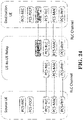
- the adaptation layer is placed over RLC sublayer for both CP and UP at the Uu interface between Relay UE and gNB.
- the Uu SDAP/PDCP and RRC are terminated between Remote UE and gNB, while RLC, MAC and PHY are terminated in each link (i.e. the link between Remote UE and UE-to-Network Relay UE and the link between UE-to-Network Relay UE and the gNB).
- the protocol stacks are similar to L2 UE-to-Network Relay other than the fact that the termination points are two Remote UEs.
- the protocol stacks for the user plane and control plane of L2 UE-to-UE Relay architecture are described in Figure 5.5.1-1 and Figure 5.5.1-2.
- An adaptation layer is supported over the second PC5 link (i.e. the PC5 link between Relay UE and Destination UE) for L2 UE-to-UE Relay.
- the adaptation layer is put over RLC sublayer for both CP and UP over the second PC5 link.
- the sidelink SDAP/PDCP and RRC are terminated between two Remote UEs, while RLC, MAC and PHY are terminated in each PC5 link.
- 3GPP TS 23.287 introduces the following:
- the UE To perform unicast mode of V2X communication over PC5 reference point, the UE is configured with the related information as described in clause 5.1.2.1.
- Figure 6.3.3.1-1 shows the layer-2 link establishment procedure for unicast mode of V2X communication over PC5 reference point.
- a UE shall apply the System Information (SI) acquisition procedure as defined in 3GPP TS 38.331 upon cell selection (e.g. upon power on), cell-reselection, return from out of coverage, after reconfiguration with sync completion, after entering the network from another RAT, upon receiving an indication that the system information has changed, upon receiving a Public Warning System (PWS) notification, upon receiving request (e.g., a positioning request) from upper layers; and whenever the UE does not have a valid version of a stored System Information Block (SIB) or posSIB or a valid version of a requested SIB.
- SIB System Information Block
- the UE when the UE acquires a MIB or a SIB1 or an SI message in a serving cell, and if the UE stores the acquired SIB, then the UE shall store the associated areaScope, the first PLMN-Identity, the cellIdentity, the systemInformationAreaID, and/or the valueTag for the SIB.
- the UE could check if a stored SIB is valid or not based on whether the first PLMN-Identity, the systemInformationAreaID, the cellIdentity and/or the valueTag for the SIB received from the serving cell are identical to the PLMN-Identity, the systemInformationAreaID, the cellIdentity and/or the valueTag associated with the stored version of that SIB.
- SIB12 System Information
- MIB Master Information Block
- SIBs which are divided into Minimum SI and Other SI.
- Minimum SI (including MIB and SIB1 as introduced in 3GPP TS 38.300) comprises basic information required for initial access and information for acquiring any other SI.
- Other SI encompasses all SIBs not broadcast in the Minimum SI. Those SIBs can either be periodically broadcast, broadcast on-demand, or sent in a dedicated manner to UEs in RRC_CONNECTED.
- UE-to-Network Relay communication is studied for UE to access network via indirect network communication.
- Rel-16 5G architectural design e.g. flow-based QoS communication over PC5/Uu interface
- a remote UE would access the network (e.g. 5GC) via a relay UE where the remote UE would be in out-of-coverage while the relay UE would be in-coverage.
- the remote UE would communicate with the relay UE via PC5 interface (or called sidelink interface) for accessing the network, while the relay UE would communicate with a base station (e.g. gNB) via Uu interface for forwarding traffic between the remote UE and the network.
- PC5 interface or called sidelink interface
- a base station e.g. gNB
- an adaptation Layer could be introduced for supporting sidelink relay communication.
- L2 Layer-2
- the adaptation layer could be placed over Radio Link Control (RLC) sublayer for both Control Plane (CP) and User Plane (UP) at the Uu interface between Relay UE and gNB.
- RLC Radio Link Control
- CP Control Plane
- UP User Plane
- SDAP Uu Service Data Adaptation Protocol
- PDCP Packet Data Convergence Protocol
- RRC Radio Resource Control
- RLC Medium Access Control
- PHY Physical
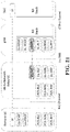
- FIG. 26 illustrates an example of protocol stacks for Layer-2 UE-to-Network Relay according to one embodiment.
- Remote UE1 could communicate with gNB via a Relay UE.
- Remote UE1 and gNB may establish one or more Uu Data Radio Bearers (DRBs) for communicating traffic.
- DRBs Uu Data Radio Bearers
- Remote UE1 and the Relay UE could establish one or more PC5 RLC channels for forwarding the traffic.
- PC5RLC channels there are three PC5RLC channels: Remote UE1's PC5 RLC channel#1, Remote UE1's PC5 RLC channel#2 and Remote UE1's PC5 RLC channel#3.
- DRB1 and DRB2 could be mapped to the Remote UE1's PC5 RLC channel#1.
- DRB3 and DRB4 could be mapped to the Remote UE1's PC5 RLC channel#2.
- DRB5 and DRB6 could be mapped to the Remote UE1's PC5 RLC channel#3.
- gNB and the Relay UE could establish one or more Uu RLC channels for forwarding the traffic.
- Uu RLC channels there are two Uu RLC channels: Uu RLC channel#1 and Uu RLC channel#2.
- the Remote UE1's PC5 RLC channel#1 and the Remote UE1's PC5 RLC channel#2 could be mapped to the Uu RLC channel#1.
- the Remote UE1's PC5 RLC channel#3 could be mapped to the Uu RLC channel#2.
- Remote UE2 could also communicate with gNB via the Relay UE.
- Remote UE2 may also have the same relay channel configuration as Remote UE1 as mentioned above.
- the Uu adaptation layer will be also supported for Uu SRBs (including e.g. Uu SRB0, Uu SRB1, Uu SRB2, and/or etc.). However, whether the PC5 adaptation layer would be also supported for the Uu SRBs is not clear. It is assumed that the PC5 adaptation layer is also supported for the Uu SRBs.
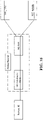
- FIG. 27 illustrates an example of association between Uu SRBs, Uu Physical Control Channel (PCCH), SL RLC channels, and Uu RLC channels according to one embodiment.
- each Uu SRB could be associated with one PC5 RLC channel (i.e. as the mapping 1 shown in FIG. 27 ), and each PC5 RLC channel could be associated with one Uu RLC channel (i.e. as the mapping 2 shown in FIG. 27 ).
- each Uu RLC channel will be associated with one Uu SRB (i.e. as the mapping 3 shown in FIG. 27 ).
- gNB can know a RRC message received from the Relay UE is sent on which Uu SRB based on which Uu RLC channel on which this RRC message is received.
- the Relay UE can know a RRC message received from gNB is to be sent on which PC5 RLC channel based on which Uu RLC channel on which this RRC message is received.
- the Remote UE can know a RRC message received from the Relay UE is sent on which Uu SRB based on which PC5 RLC channel on which this RRC message is received.
- Uu PCCH used for monitoring or receiving paging messages, according to 3GPP TS 38.331, there is no associated signalling radio bearer. Thus, Uu PCCH could be associated with one PC5 RLC channel (i.e. as the mapping 1 and 2 shown in FIG. 27 ). If Relay UE monitors or receives a paging message for a Remote UE, this Relay UE could send the paging message on the PC5 RLC channel associated with Uu PCCH to the Remote UE. When the Remote UE receives a transport block on the PC5 RLC channel associated with Uu PCCH, the Remote UE could know the transport block may include the paging message for the Remote UE.
- each Uu RLC channel could be associated with one Remote UE
- gNB and the Relay UE can further know a RRC message is sent on which Uu SRB of which Remote UE.
- gNB may know a RRC message received from the Relay UE is sent on which Uu SRB and is associated with which Remote UE based on association between a Remote UE and a Uu RLC channel and association between a Uu SRB and the Uu RLC channel on which this RRC message is received.
- the Relay UE can know a RRC message received from gNB is to be sent on which PC5 RLC channel of which Remote UE based on association between a Remote UE and a Uu RLC channel and association between a PC5 RLC channel and the Uu RLC channel on which this RRC message is received.
- the range of Uu RLC channel ID e.g. from 1 to 65536
- the range of PC5 RLC channel ID could be larger than (or equal to) the range of PC5 RLC channel ID (e.g. from 1 to 32).
- association between Uu SRB and PC5 RLC channel could be specified with default configuration or pre-configured in UE.
- Association between PC5 RLC channel and Uu RLC channel i.e. the mapping 2) could be specified with default configuration, pre-configured in UE, configured by network (i.e. base station, gNB, via e.g. dedicated signalling or system information (e.g. SIB)) or configured by Relay UE.
- Association between Uu SRB and Uu RLC channel i.e. the mapping 3 could be specified with default configuration, pre-configured in UE or configured by network (i.e. base station, gNB, via e.g. dedicated signalling or system information (e.g. SIB)).
- Association between Uu PCCH and PC5 RLC channel could be specified with default configuration or pre-configured in UE (i.e. the mapping 1) or configured by network (i.e. base station, gNB, via e.g. dedicated signalling or system information (e.g. SIB)) or configured by Relay UE (i.e. the mapping 2).
- network i.e. base station, gNB, via e.g. dedicated signalling or system information (e.g. SIB)
- Relay UE i.e. the mapping 2
- the UE in RRC_IDLE and RRC_INACTIVE state may use Discontinuous Reception (DRX) to monitor one paging occasion (PO) per DRX cycle in order to reduce power consumption.
- a PO is a set of PDCCH monitoring occasions and can consist of multiple time slots (e.g. subframe or OFDM symbol) where paging downlink control information (DCI) can be sent.
- DCI paging downlink control information
- One Paging Frame (PF) is one Radio Frame and may contain one or multiple PO(s) or starting point of a PO.
- the UE needs to register with the network to get authorized to receive services, to enable mobility tracking and to enable reachability.
- the UE When the UE has registered onto the network, the UE has 5G-S-TMSI. And then, the both PO and PF are determined by the UE_ID which is derived from the 5G-S-TMSI of the UE (i.e. 5G-S-TMSI mod 1024).
- forwarding system information received from the serving cell of a Relay UE to a Remote UE could be supported in UE-to-Network relay communication.
- forwarding paging messages received from the serving cell of the Relay UE to the Remote UE could be also supported.
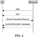
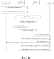
- step flow used for acquiring system information and/or paging messages of a cell (controlled by gNB2) via a Relay UE locating at the cell and forwarding the system information and/or the paging messages to the Remote UE (which may have originally registered onto the network via gNB1) could be considered and illustrated in FIG. 28 , which illustrates an exemplary flow chart for paging monitoring via Reley UE starting from Remote UE in RRC_IDLE according to one embodiment:
- the PLMN related information e.g. PLMN ID
- the RNA related information e.g. RNA area ID
- Step 3 the discovery messages sent by Relay UE as Step 3.
- UE1 could receive the minimum SI after Relay UE selection is done (i.e. behind Step 5).
- a Relay UE could broadcast the minimum SI if or when the Relay UE connects to one or more Remote UEs. Connecting to Remote UE could mean that the Relay UE has established one direct link with this Remote UE.
- the Relay UE could perform a unicast link establishment procedure with the Remote UE for establishing the direct link between the Relay UE and the Remote UE.
- the direct link could be established and used for forwarding traffic between the Remote UE and the network (e.g. a base station, gNB).
- a Relay UE could broadcast the minimum SI if or when the Relay UE is performing transmission of one or more discovery messages.
- Performing transmission of one or more discovery messages could mean that the Relay UE is performing a Model A discovery procedure or a Model B discovery procedure
- the Relay UE could transmit one or more discovery messages (i.e. the Announcement message) for a period.
- the Relay UE could transmit one or more discovery messages (i.e. the Response message).
- a Relay UE could broadcast the minimum SI if or when the Relay UE is monitoring paging for one or more Remote UEs.
- Monitoring paging for one or more Remote UEs could mean that the Relay UE has determined one or more paging occasions according to these Remote UEs' UE IDs (e.g. S-TMSIs of these Remote UEs) and is monitoring potential paging at these paging occasions.
- a UE only in RRC_IDLE or RRC_INACTIVE can monitor paging. Since UE2 may be in RRC_CONNECTED, UE2 is not able to monitor or receive paging messages for UE1 if UE2 still follows the principle of monitoring paging as in 3GPP TS 38.331. To address this, UE2 could be able to monitor paging for UE1 while UE2 is in RRC_CONNECTED and needs for monitoring or forwarding UE1's paging messages.
- gNB could send paging messages to UE2 via dedicated signing (via RRCReconfiguration or other RRC message sent on PDCCH addressed to UE2) while UE2 is in RRC _CONNECTED and needs for monitoring or forwarding UE1's paging messages. If/when/after/upon UE2 receives UE1's paging messages in the dedicated signalling, UE2 may then send the UE1's paging messages to UE1 (via e.g. PC5 RRC messages).
- the UE when a UE entering RRC_INACTIVE, the UE should store UE Inactive AS context with some parameters including e.g. C-RNTI of a serving cell this UE was connected to prior to suspension of the RRC connection, PhysCellId of the serving cell, CellIdentity of the serving cell, etc. At least one of these stored parameters is used for determining content of authentication information (e.g. resumeMAC-I or VarResumeMAC-Input ) when this UE enters RRC_CONEECTED from RRC_INACTIVE.
- the authentication information could be included in a request message of resuming RRC connection (e.g. RRCResumeRequest or RRCResumeRequest1 ).
- gNB2 may also provide at least one of these parameters (e.g. C-RNTI, PhysCellId, CellIdentity, etc.) in the RRC message used for switching UE1 to enter RRC_INACTIVE (e.g. the fourth RRC message as in Step 11 in FIG. 28 or the second RRC message as in Step 9 in FIG. 29 ).
- these parameters e.g. C-RNTI, PhysCellId, CellIdentity, etc.
- UE1 may then:
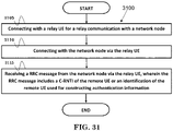
- FIG. 30 is a flow chart 3000 illustrating a method for a remote UE to support UE-to-Network relay communication.
- the remote UE connects with a relay UE.
- the remote UE connects with a first network node via the relay UE.
- the remote UE receives a first RRC message from the first network node via the relay UE, wherein the first RRC message includes a C-RNTI of the remote UE used for constructing authentication information.
- the remote UE could establish a RRC connection between the remote UE and the first network node via the relay UE.
- the remote UE could also enter a RRC_CONNECTED if establishment of the RRC connection is completed.
- the remote UE could enter a RRC_INACTIVE from the RRC_CONNECTED in response to reception of the first RRC message from the first network node via the relay UE.
- the first RRC message could be a RRCRelease message including suspendConfig or a RRC message for release or suspension of the RRC connection.
- the remote UE could transmit a second RRC message to the first network node via the relay UE or directly to a second network node for request of resuming the RRC connection.
- the second RRC message may include the authentication information.
- the first or second network node may be a base station (e.g., gNB).
- the second RRC message may be a RRCResumeRequest or RRCResumeRequest1 message.
- the authentication information may be resumeMAC-I.
- the remote UE 300 includes a program code 312 stored in the memory 310.
- the CPU 308 could execute program code 312 to enable the remote UE (i) to connect with a relay UE, (ii) to connect with a first network node via the relay UE, and (iii) to receive a first RRC message from the first network node via the relay UE, wherein the first RRC message includes a C-RNTI of the remote UE used for constructing authentication information.
- the CPU 308 can execute the program code 312 to perform all of the above-described actions and steps or others described herein.
- FIG. 31 is a flow chart 3100 illustrating a method for a remote UE to support UE-to-Network relay communication.
- the remote UE connects with a relay UE for a relay communication with a network node.
- the remote UE connects with the network node via the relay UE.
- the remote UE receives a RRC message from the network node via the relay UE, wherein the RRC message includes a C-RNTI of the remote UE or an identification of the remote UE used for constructing authentication information.
- the remote UE could transmit a first PC5-S message for request of establishing a PC5-S connection to the relay UE.
- the remote UE could also receive a second PC5-S message for acceptation of establishing the PC5-S connection from the relay UE.
- the remote UE could transmit a first RRC message for request of establishing the RRC connection to the network node via the relay UE.
- the remote UE could receive a second RRC message for setup of establishing the RRC connection from the network node via the relay UE.
- the remote UE could also transmit a third RRC message for completion of establishing the RRC connection to the network node via the relay UE.
- the remote UE could enter a RRC_CONNECTED if the RRC connection is completed.
- the RRC message may be a RRC message for release or suspension of the RRC connection.
- the remote UE could enter a RRC_INACTIVE from the RRC_CONNECTED if the RRC message for release or suspension of the RRC connection is received from the network node via the relay UE.
- the RRC message for release or suspension of the RRC connection may also include at least one of an identification used for identifying the remote UE (e.g. fullI-RNTI and/or shortI-RNTI), a paging cycle (e.g.
- ran-PagingCycle a RAN-NotificationAreaInfo, a PeriodicRNAU-TimerValue, a cellIdentity (of a serving cell of the relay UE or the network node), and/or a PhysCellId (of the serving cell of the relay UE or the network node).
- the remote UE could transmit a fourth RRC message for request of resuming the RRC connection to the network node via the relay UE.
- the fourth RRC message may include the authentication information.
- the fourth RRC message may also include the identification used for identifying the remote UE (e.g. fullI-RNTI and/or shortI-RNTI).
- the authentication information could be constructed with the cellIdentity and/or the PhysCellId.
- the authentication information may be resumeMAC-I.
- the network node may be a base station (e.g. gNB).
- gNB base station
- the remote UE 300 includes a program code 312 stored in the memory 310.
- the CPU 308 could execute program code 312 to enable the remote UE (i) to connect with a relay UE for a relay communication with a network node, (ii) to connect with the network node via the relay UE, and (iii) to receive a RRC message from the network node via the relay UE, wherein the RRC message includes a C-RNTI of the remote UE or an identification of the remote UE used for constructing authentication information.
- the CPU 308 can execute the program code 312 to perform all of the above-described actions and steps or others described herein.
- concurrent channels could be established based on pulse repetition frequencies.
- concurrent channels could be established based on pulse position or offsets.
- concurrent channels could be established based on time hopping sequences.
- concurrent channels could be established based on pulse repetition frequencies, pulse positions or offsets, and time hopping sequences.
- the various illustrative logical blocks, modules, and circuits described in connection with the aspects disclosed herein may be implemented within or performed by an integrated circuit ("IC"), an access terminal, or an access point.
- the IC may comprise a general purpose processor, a digital signal processor (DSP), an application specific integrated circuit (ASIC), a field programmable gate array (FPGA) or other programmable logic device, discrete gate or transistor logic, discrete hardware components, electrical components, optical components, mechanical components, or any combination thereof designed to perform the functions described herein, and may execute codes or instructions that reside within the IC, outside of the IC, or both.
- a general purpose processor may be a microprocessor, but in the alternative, the processor may be any conventional processor, controller, microcontroller, or state machine.
- a processor may also be implemented as a combination of computing devices, e.g., a combination of a DSP and a microprocessor, a plurality of microprocessors, one or more microprocessors in conjunction with a DSP core, or any other such configuration.
- a software module e.g., including executable instructions and related data
- other data may reside in a data memory such as RAM memory, flash memory, ROM memory, EPROM memory, EEPROM memory, registers, a hard disk, a removable disk, a CD-ROM, or any other form of computer-readable storage medium known in the art.
- a sample storage medium may be coupled to a machine such as, for example, a computer/processor (which may be referred to herein, for convenience, as a "processor") such the processor can read information (e.g., code) from and write information to the storage medium.
- a sample storage medium may be integral to the processor.
- the processor and the storage medium may reside in an ASIC.
- the ASIC may reside in user equipment.
- the processor and the storage medium may reside as discrete components in user equipment.
- any suitable computer-program product may comprise a computer-readable medium comprising codes relating to one or more of the aspects of the disclosure.
- a computer program product may comprise packaging materials.
Landscapes
- Engineering & Computer Science (AREA)
- Computer Networks & Wireless Communication (AREA)
- Signal Processing (AREA)
- Computer Security & Cryptography (AREA)
- Mobile Radio Communication Systems (AREA)
Applications Claiming Priority (1)
| Application Number | Priority Date | Filing Date | Title |
|---|---|---|---|
| US202063117090P | 2020-11-23 | 2020-11-23 |
Publications (1)
| Publication Number | Publication Date |
|---|---|
| EP4002953A1 true EP4002953A1 (fr) | 2022-05-25 |
Family
ID=78371908
Family Applications (1)
| Application Number | Title | Priority Date | Filing Date |
|---|---|---|---|
| EP21204112.3A Pending EP4002953A1 (fr) | 2020-11-23 | 2021-10-22 | Procédé et appareil d'acquisition d'informations de système et de radiomessagerie par l'intermédiaire d'un relais équipement utilisateur-réseau dans un système de communication sans fil |
Country Status (4)
| Country | Link |
|---|---|
| US (1) | US12120758B2 (fr) |
| EP (1) | EP4002953A1 (fr) |
| KR (1) | KR20220071107A (fr) |
| CN (1) | CN114615719A (fr) |
Families Citing this family (16)
| Publication number | Priority date | Publication date | Assignee | Title |
|---|---|---|---|---|
| EP4593520A3 (fr) * | 2017-06-16 | 2025-10-29 | Telefonaktiebolaget LM Ericsson (publ) | Reprise d'une connexion dans un système de communication sans fil |
| EP4149184A4 (fr) * | 2020-05-07 | 2024-08-07 | Hyundai Motor Company | Procédé et dispositif de radiomessagerie dans une communication de liaison latérale |
| EP4009732B1 (fr) * | 2020-12-02 | 2023-03-22 | ASUSTek Computer Inc. | Procédés et appareil de prise en charge de communication par relais d'équipement utilisateur (ue) à réseau dans un système de communication sans fil |
| US20240007908A1 (en) * | 2021-01-07 | 2024-01-04 | Sony Group Corporation | Communications device, infrastructure equipment and methods |
| JP7624519B2 (ja) * | 2021-01-11 | 2025-01-30 | テレフオンアクチーボラゲット エルエム エリクソン(パブル) | Ue対ネットワークリレーディスカバリのためのディスカバリキーハンドリング |
| EP4278701A1 (fr) * | 2021-01-15 | 2023-11-22 | Qualcomm Incorporated | Techniques permettant de relayer des informations de système sur une liaison latérale |
| CN116349402A (zh) * | 2021-02-05 | 2023-06-27 | Oppo广东移动通信有限公司 | 状态转换方法、装置、设备及存储介质 |
| US12127112B2 (en) * | 2021-07-26 | 2024-10-22 | Qualcomm Incorporated | Integrated access and backhaul sidelink communications |
| US12207330B2 (en) * | 2021-09-09 | 2025-01-21 | Asustek Computer Inc. | Method and apparatus for supporting multiple connectivity services in a wireless communication system |
| US12058683B2 (en) * | 2021-09-21 | 2024-08-06 | Qualcomm Incorporated | Direct current location with bandwidth part (BWP) hopping |
| EP4539581A4 (fr) * | 2022-06-13 | 2025-06-25 | Beijing Xiaomi Mobile Software Co., Ltd. | Procédé et appareil de commande d'accès |
| CN117545042A (zh) * | 2022-08-02 | 2024-02-09 | 华为技术有限公司 | 一种通信方法、通信装置及通信系统 |
| CN117560647A (zh) * | 2022-08-05 | 2024-02-13 | 中国电信股份有限公司 | 呼叫控制方法及装置、电子设备、存储介质 |
| WO2024036563A1 (fr) * | 2022-08-18 | 2024-02-22 | Mediatek Inc. | Architecture de système étendu pour prendre en charge une configuration à trajets multiples |
| CN117715247A (zh) * | 2022-09-06 | 2024-03-15 | 夏普株式会社 | 由用户设备执行的方法及用户设备 |
| CN116707713B (zh) * | 2023-08-02 | 2023-10-27 | 上海星思半导体有限责任公司 | Rlc层状态包的发送方法、接收方法、装置及处理器 |
Citations (1)
| Publication number | Priority date | Publication date | Assignee | Title |
|---|---|---|---|---|
| WO2020032850A1 (fr) * | 2018-08-06 | 2020-02-13 | Telefonaktiebolaget Lm Ericsson (Publ) | Équipement d'utilisateur et procédé dans un réseau de communication sans fil |
Family Cites Families (9)
| Publication number | Priority date | Publication date | Assignee | Title |
|---|---|---|---|---|
| KR102571341B1 (ko) * | 2017-02-03 | 2023-08-29 | 주식회사 아이티엘 | 무선 통신 시스템에서 단말의 이동성을 지원하는 네트워크 및 단말의 동작 방법 및 장치 |
| US11109434B2 (en) * | 2017-02-06 | 2021-08-31 | Lg Electronics Inc. | Method for handling of a RRC connection request message of a remote UE by a relay UE in wireless communication system and a device therefor |
| WO2018155908A1 (fr) * | 2017-02-22 | 2018-08-30 | 엘지전자(주) | Procédé de transmission ou de réception de données par l'intermédiaire d'un relais dans un système de communication sans fil et appareil associé |
| US11259269B2 (en) * | 2017-03-17 | 2022-02-22 | Lg Electronics Inc. | Method and base station for performing paging, and method and network entity for supporting paging |
| US11259360B2 (en) * | 2018-02-26 | 2022-02-22 | Nokia Technologies Oy | Multicast traffic area management and mobility for wireless network |
| US11553550B2 (en) * | 2018-07-04 | 2023-01-10 | Lg Electronics Inc. | Method and apparatus for supporting security in RRC inactive state in wireless communication system |
| WO2022036671A1 (fr) * | 2020-08-21 | 2022-02-24 | Qualcomm Incorporated | Configuration de mesure pendant un transfert de données de liaison montante sur un accès aléatoire ou des ressources de liaison montante dédiées |
| CN116195340A (zh) * | 2020-09-18 | 2023-05-30 | 三星电子株式会社 | 用于小数据传输的pdcch监视的方法和装置 |
| CN116368848A (zh) * | 2020-10-15 | 2023-06-30 | 瑞典爱立信有限公司 | 用于处理上行链路传输的无线设备、网络节点及其执行的方法 |
-
2021
- 2021-10-22 CN CN202111232677.4A patent/CN114615719A/zh active Pending
- 2021-10-22 EP EP21204112.3A patent/EP4002953A1/fr active Pending
- 2021-10-22 US US17/508,327 patent/US12120758B2/en active Active
- 2021-10-22 KR KR1020210141974A patent/KR20220071107A/ko active Pending
Patent Citations (1)
| Publication number | Priority date | Publication date | Assignee | Title |
|---|---|---|---|---|
| WO2020032850A1 (fr) * | 2018-08-06 | 2020-02-13 | Telefonaktiebolaget Lm Ericsson (Publ) | Équipement d'utilisateur et procédé dans un réseau de communication sans fil |
Non-Patent Citations (24)
| Title |
|---|
| "3rd Generation Partnership Project; Technical Specification Group Radio Access Network; Evolved Universal Terrestrial Radio Access (E-UTRA) and Evolved Universal Terrestrial Radio Access Network (E-UTRAN); Overall description; Stage 2 (Release 16)", vol. RAN WG2, no. V16.0.0, 8 January 2020 (2020-01-08), pages 1 - 366, XP051860576, Retrieved from the Internet <URL:ftp://ftp.3gpp.org/Specs/archive/36_series/36.300/36300-g00.zip 36300-g00.docx> [retrieved on 20200108] * |
| "3rd Generation Partnership Project; Technical Specification Group Services and System Aspects; Study on Architecture Enhancements to ProSe UE-to-Network Relay (Release 15)", 3GPP STANDARD ; TECHNICAL REPORT ; 3GPP TR 23.733, 3RD GENERATION PARTNERSHIP PROJECT (3GPP), MOBILE COMPETENCE CENTRE ; 650, ROUTE DES LUCIOLES ; F-06921 SOPHIA-ANTIPOLIS CEDEX ; FRANCE, vol. SA WG2, no. V15.0.0, 18 September 2017 (2017-09-18), pages 1 - 81, XP051336980 * |
| "5G; Security architecture and procedures for 5G System (3GPP TS 33.501 version 16.3.0 Release 16)", vol. 3GPP SA, no. V16.3.0, 10 August 2020 (2020-08-10), pages 1 - 251, XP014380028, Retrieved from the Internet <URL:http://www.etsi.org/deliver/etsi_ts/133500_133599/133501/16.03.00_60/ts_133501v160300p.pdf> [retrieved on 20200810] * |
| 3GPP 38.331 |
| 3GPP TR 23.752 |
| 3GPP TR 38.836 |
| 3GPP TR23.752 |
| 3GPP TS 23.287 |
| 3GPP TS 23.502 |
| 3GPP TS 38.300 |
| 3GPP TS 38.331 |
| TR 23.733 |
| TR 23.752 |
| TR 36.746 |
| TR 38.836 |
| TR23.752 |
| TS 23.122 |
| TS 23.287 |
| TS 23.501 |
| TS 23.502 |
| TS 38.212 |
| TS 38.213 |
| TS 38.300 |
| TS 38.331 |
Also Published As
| Publication number | Publication date |
|---|---|
| US12120758B2 (en) | 2024-10-15 |
| CN114615719A (zh) | 2022-06-10 |
| US20220174762A1 (en) | 2022-06-02 |
| KR20220071107A (ko) | 2022-05-31 |
Similar Documents
| Publication | Publication Date | Title |
|---|---|---|
| US12120758B2 (en) | Method and apparatus for acquiring system information and paging via UE-to-network relay in a wireless communication system | |
| US11997642B2 (en) | Method and apparatus for acquiring system information and paging via UE-to-network relay in a wireless communication system | |
| US11864157B2 (en) | Method and apparatus for avoiding paging collision in a wireless communication system | |
| US12004243B2 (en) | Method and apparatus for supporting UE-to-network relay communication in a wireless communication system | |
| US20220141756A1 (en) | Method and apparatus for system information acquisition via ue-to-network relay in a wireless communication system | |
| US20190239147A1 (en) | Method for connecting to network and user equipment | |
| KR102052146B1 (ko) | 무선 통신 시스템에서 단말에 의해 수행되는 d2d(device-to-device) 동작 방법 및 상기 방법을 이용하는 단말 | |
| US20230171825A1 (en) | Method and apparatus for remote user equipment (ue) to perform direct to indirect path switching in a wireless communication system | |
| EP4178306A1 (fr) | Procédé et appareil d'établissement de connexion rrc pour prendre en charge un relais d'ue à réseau dans un système de communication sans fil | |
| WO2015046973A1 (fr) | Procédé de communication d2d mis en œuvre par des terminaux dans un système de communication sans fil, et dispositifs destinés à le prendre en charge | |
| CN106688279B (zh) | 在无线通信系统中由终端执行的装置对装置d2d操作方法和使用该方法的终端 | |
| WO2015115824A1 (fr) | Procédé de création de rapport d'état d'opération relais exécutée par un terminal dans un système de communication radio, et terminal l'utilisant | |
| CN106233785B (zh) | 在无线通信系统中由终端执行的装置对装置(d2d)操作方法及使用该方法的终端 | |
| CN106105356A (zh) | 在无线通信系统中由终端执行的装置对装置(d2d)操作的方法及使用该方法的终端 | |
| KR20230009821A (ko) | 무선 통신 시스템에서 ue-대-네트워크 릴레잉을 지원하기 위한 무선 베어러 구성을 위한 방법 및 장치 | |
| US20250374239A1 (en) | Method and Apparatus for Paging Reception Via UE-to-Network Relay in a Wireless Communication System | |
| KR20230037466A (ko) | 무선 통신 시스템에서 다수의 연결성 서비스들을 지원하기 위한 방법 및 장치 | |
| KR20250017681A (ko) | 무선 통신 시스템에서 ue-대-네트워크 릴레이 발견을 위한 다중-홉 ue에 대한 방법 및 장치 | |
| WO2016064232A2 (fr) | Procédé d'exécution d'une opération de dispositif à dispositif (d2d), au moyen d'une ressource exceptionnelle, par un équipement utilisateur dans un système de communication sans fil, et équipement utilisateur employant ce procédé | |
| KR102356005B1 (ko) | 무선 통신 시스템에서 단말에 의해 수행되는 d2d(device-to-device) 관련 보고 방법 및 상기 방법을 이용하는 단말 | |
| HK40075286A (en) | Method and apparatus for acquiring system information and paging via ue-to-network relay in a wireless communication system | |
| US20250031128A1 (en) | Method and apparatus for supporting multi-hop ue-to-network relay in a wireless communication system | |
| WO2025154045A1 (fr) | Techniques d'économie d'énergie de réseau pour réduire au minimum des transmissions de radiomessagerie |
Legal Events
| Date | Code | Title | Description |
|---|---|---|---|
| PUAI | Public reference made under article 153(3) epc to a published international application that has entered the european phase |
Free format text: ORIGINAL CODE: 0009012 |
|
| STAA | Information on the status of an ep patent application or granted ep patent |
Free format text: STATUS: THE APPLICATION HAS BEEN PUBLISHED |
|
| STAA | Information on the status of an ep patent application or granted ep patent |
Free format text: STATUS: REQUEST FOR EXAMINATION WAS MADE |
|
| AK | Designated contracting states |
Kind code of ref document: A1 Designated state(s): AL AT BE BG CH CY CZ DE DK EE ES FI FR GB GR HR HU IE IS IT LI LT LU LV MC MK MT NL NO PL PT RO RS SE SI SK SM TR |
|
| 17P | Request for examination filed |
Effective date: 20220511 |
|
| RBV | Designated contracting states (corrected) |
Designated state(s): AL AT BE BG CH CY CZ DE DK EE ES FI FR GB GR HR HU IE IS IT LI LT LU LV MC MK MT NL NO PL PT RO RS SE SI SK SM TR |
|
| REG | Reference to a national code |
Ref country code: HK Ref legal event code: DE Ref document number: 40075286 Country of ref document: HK |
|
| STAA | Information on the status of an ep patent application or granted ep patent |
Free format text: STATUS: EXAMINATION IS IN PROGRESS |
|
| 17Q | First examination report despatched |
Effective date: 20250307 |