EP4002959B1 - Luminaire d'éclairage public à émission lumineuse sensible à la météo - Google Patents
Luminaire d'éclairage public à émission lumineuse sensible à la météo Download PDFInfo
- Publication number
- EP4002959B1 EP4002959B1 EP21207812.5A EP21207812A EP4002959B1 EP 4002959 B1 EP4002959 B1 EP 4002959B1 EP 21207812 A EP21207812 A EP 21207812A EP 4002959 B1 EP4002959 B1 EP 4002959B1
- Authority
- EP
- European Patent Office
- Prior art keywords
- street lamp
- electrodes
- resistance
- lamp according
- capacitance
- Prior art date
- Legal status (The legal status is an assumption and is not a legal conclusion. Google has not performed a legal analysis and makes no representation as to the accuracy of the status listed.)
- Active
Links
Images


Classifications
-
- H—ELECTRICITY
- H05—ELECTRIC TECHNIQUES NOT OTHERWISE PROVIDED FOR
- H05B—ELECTRIC HEATING; ELECTRIC LIGHT SOURCES NOT OTHERWISE PROVIDED FOR; CIRCUIT ARRANGEMENTS FOR ELECTRIC LIGHT SOURCES, IN GENERAL
- H05B47/00—Circuit arrangements for operating light sources in general, i.e. where the type of light source is not relevant
- H05B47/10—Controlling the light source
- H05B47/105—Controlling the light source in response to determined parameters
-
- G—PHYSICS
- G01—MEASURING; TESTING
- G01N—INVESTIGATING OR ANALYSING MATERIALS BY DETERMINING THEIR CHEMICAL OR PHYSICAL PROPERTIES
- G01N27/00—Investigating or analysing materials by the use of electric, electrochemical, or magnetic means
- G01N27/02—Investigating or analysing materials by the use of electric, electrochemical, or magnetic means by investigating impedance
- G01N27/04—Investigating or analysing materials by the use of electric, electrochemical, or magnetic means by investigating impedance by investigating resistance
- G01N27/12—Investigating or analysing materials by the use of electric, electrochemical, or magnetic means by investigating impedance by investigating resistance of a solid body in dependence upon absorption of a fluid; of a solid body in dependence upon reaction with a fluid, for detecting components in the fluid
- G01N27/121—Investigating or analysing materials by the use of electric, electrochemical, or magnetic means by investigating impedance by investigating resistance of a solid body in dependence upon absorption of a fluid; of a solid body in dependence upon reaction with a fluid, for detecting components in the fluid for determining moisture content, e.g. humidity, of the fluid
-
- G—PHYSICS
- G01—MEASURING; TESTING
- G01N—INVESTIGATING OR ANALYSING MATERIALS BY DETERMINING THEIR CHEMICAL OR PHYSICAL PROPERTIES
- G01N27/00—Investigating or analysing materials by the use of electric, electrochemical, or magnetic means
- G01N27/02—Investigating or analysing materials by the use of electric, electrochemical, or magnetic means by investigating impedance
- G01N27/22—Investigating or analysing materials by the use of electric, electrochemical, or magnetic means by investigating impedance by investigating capacitance
- G01N27/223—Investigating or analysing materials by the use of electric, electrochemical, or magnetic means by investigating impedance by investigating capacitance for determining moisture content, e.g. humidity
-
- G—PHYSICS
- G01—MEASURING; TESTING
- G01W—METEOROLOGY
- G01W1/00—Meteorology
- G01W1/14—Rainfall or precipitation gauges
-
- H—ELECTRICITY
- H05—ELECTRIC TECHNIQUES NOT OTHERWISE PROVIDED FOR
- H05B—ELECTRIC HEATING; ELECTRIC LIGHT SOURCES NOT OTHERWISE PROVIDED FOR; CIRCUIT ARRANGEMENTS FOR ELECTRIC LIGHT SOURCES, IN GENERAL
- H05B45/00—Circuit arrangements for operating light-emitting diodes [LED]
- H05B45/20—Controlling the colour of the light
Definitions
- the present invention relates to a street lamp which is designed to change a light output depending on the weather.
- the weather has a strong influence on visibility in road traffic.
- the lighting task of a street light changes when it is snowing or raining. Lighting that is perceived as ideal when it is dry and visibility is good can lead to strong scattering or glare when it is raining, which road users find unpleasant and tiring. This can also have a negative impact on road safety.
- EP 2 884 312 A1 discloses a street light according to the preamble of claim 1. Further lights and weather sensors are described in the publications US 2018/124900 A1 , CN 106 704 979 A , GB 966 769 A , JP 2010 107528 A and US 2007/132599 A1 revealed.
- the object of the present invention is to provide a street light which can fulfil its lighting task in the best possible way even in changing weather conditions.
- a special feature of the street light according to the present invention is a weather sensor which is designed to reliably detect rain and/or snow.
- the weather sensor has at least one The sensor has a pair of electrodes on an insulating body and is designed to measure the resistance or capacitance between the two electrodes. If the electrodes are spaced apart and there is no conductive material between them, the resistance is of course very high. However, if moisture gets between the electrodes, the resistance decreases. Alternatively, the moisture between the electrodes can also be determined by determining the capacitance. Therefore, the level of resistance or the level of capacitance can be used directly to adapt the lamp to the weather conditions.
- the luminous flux can be changed in order to reduce secondary glare for road users caused by light reflected from the surface of rain or snow.
- the color of the light can also be changed. It is known that the blue component of the light leads to greater glare than the red component. For example, if snow or rain is detected, the red component can be increased compared to the blue component so that the glare is reduced.
- the street light has at least three electrodes, two electrodes being arranged at a smaller distance and the third electrode at a greater distance from one of the first two electrodes, and the electronic circuit is designed to measure both the resistance or capacitance between the two electrodes that are closer together and the resistance or capacitance between the two electrodes that are further apart.
- the electronic circuit is designed to measure both the resistance or capacitance between the two electrodes that are closer together and the resistance or capacitance between the two electrodes that are further apart.
- the larger of the two electrode spacings is arranged in a vertical direction and the street light has a plane below the two further apart electrodes on which snow can collect, so that when snow falls, the larger spacing between the two electrodes can be bridged by snow.
- the snow collecting on the plane can gradually form an increasingly thick layer, so that the larger spacing between the two electrodes is partially or completely bridged.
- the resistance or capacitance measurement can therefore be used to determine whether snow is present and, if applicable, even how much snow there is.
- This embodiment is therefore particularly advantageous for being able to control the light in response to changed weather conditions with regard to a continuous blanket of snow.
- the two other electrodes which are arranged at a smaller distance from one another, can be used independently to determine rain.
- the defined distance between the two electrodes is in the range of 1 mm to 10 mm and in the embodiment with three electrodes the larger distance between the second electrode and the third electrode is in the range of 10 mm to 20 mm.
- the smaller distance of 1 mm to 10 mm is suitable for detecting rain, while the larger distance of 10 mm to 20 mm is particularly suitable for detecting snow.
- one of the electrodes consists of a lamp housing, a lamp post or another structural component of the street lamp which is made of metal. At least one of the two or three electrodes can be formed by a metallic component of the lamp.
- the lamp housing itself can serve as an electrode, since it is made of a metallic material anyway.
- a lamp mast, a lamp mast boom or another supporting or covering part of the lamp can also serve as an electrode, provided that one or the other two electrodes are arranged separately from this component with an insulating body. This simplifies the structure of the lamp because a separate electrode can be saved.
- the insulating body is a cylindrical body, which is preferably arranged vertically on the lamp.
- the cylindrical insulating body has the advantage that it provides the same surface geometry symmetrically on all sides.
- the electrodes can, for example, be attached as continuous rings on the cylinder surface. This structure will always react to the precipitation in the same way with a change in resistance or capacitance, regardless of the direction from which the precipitation hits the sensor.
- the insulating body is exchangeable in order to adjust the distance between the two electrodes by selecting the insulating body with a thickness of the insulating body corresponding to the desired distance.
- the structure of the weather sensor is particularly simple and yet allows adaptation for the detection of different types of precipitation.
- a thicker insulating disc can be used to detect snow and a thinner Insulation disc can be selected for detecting rain.
- One electrode can be formed, for example, by a cylindrical metallic body on the insulation disc and the other of the at least two electrodes by a housing surface or another surface of the lamp below the insulation disc.
- an electrically insulating, absorbent spacer is provided between the two electrodes, with at least one side of the absorbent spacer being exposed to weather conditions so that it can absorb moisture from precipitation.
- the spacer absorbs moisture.
- the absorbent spacer only dries out after a time delay, so that the measurement of the change in resistance or capacitance only responds to the changed weather conditions after a certain time delay.
- This time delay can be set by selecting the thickness of the spacer so that it corresponds to the drying of the road after the rain has stopped. This allows the light output of the lamp to be adjusted according to the condition of the road without a time delay in the electronic control of the lamp being necessary.
- This embodiment is therefore particularly preferred for lamps that do not have a complex electronic control in a ballast for the lamps or other electronic components.
- This embodiment is therefore also particularly suitable for retrofitting lamps that do not have a corresponding complex electronic control device.
- the weather sensor can easily be used to control an existing conventional ballast of the luminaire.
- one of the two electrodes on the absorbent spacer is designed as a grid electrode.
- the grid electrode ensures that the absorbent spacer is exposed to the weather conditions on at least one side, so that the spacer can absorb moisture like a sponge when precipitation begins and can slowly release the moisture again once the precipitation has stopped.
- the spacer is arranged opposite a heat-generating component of the lamp, in particular a light source, in such a way that the spacer can heat up during operation of the lamp through the component, e.g. through heat transfer or through heat radiation.
- the arrangement of the absorbent spacer near a component that generates heat during operation of the lamp has the advantage that the drying speed of the spacer after the rain has stopped is increased under the influence of the heat generated by the lamp during operation. This means that the time constant with which the spacer dries out after the rain has stopped can be adapted to the drying speed of the road surface.
- the control circuit is designed such that, in the event of a measured reduction in resistance or a measured reduction in capacitance, it reduces the luminous flux and/or shifts a ratio of the light colors blue and red further towards red. While on a dry road a relatively large amount of light from the street lamp is absorbed by the dark color of the road surface, on a wet road a higher proportion of the light is reflected or scattered. This reflected or scattered light can be used for a Glare for road users. In order to reduce this glare, the luminaire according to the invention simply reduces the intensity of a luminous flux.
- the luminous flux with reduced intensity is also sufficient to produce an adequate level of illumination.
- the luminous flux can be reduced by dimming lamps or by changing the light distribution of the luminaire to a wider light distribution.
- the ratio of the light colors blue and red can also be adjusted. Blue light is known to cause more glare than red light. Glare can therefore be reduced by reducing the blue component and increasing the red component. While white light is preferred in dry road conditions for a true-color reproduction of the road, glare is reduced in rainy or snowy conditions by changing the color reproduction. This means that the color fidelity is no longer the same as in dry road conditions, but this is not necessary in critical weather conditions.
- the control circuit is designed to reduce the luminous flux even further and/or to change the ratio of the light colors even further towards red light if a reduced resistance or a reduced capacitance is also measured between the two further spaced electrodes.
- a snow surface reflects or scatters the light of the street light even more than a rain-soaked surface. Therefore, in this embodiment, it is provided that the changes in the lighting during the Detection of a snow surface is enhanced by the further spaced electrodes to further reduce the increased secondary glare due to the snow surface.
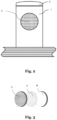
- FIG. 1a to 1c various embodiments of weather sensors for street lights according to the invention are shown.
- the street light itself is not shown, but only a section 3 of its light housing.
- the weather sensor has a cylindrical insulating body 1, on whose surface two electrodes A and B are arranged.
- the electrodes A and B are provided as concentric rings one above the other with a defined distance between the electrodes, which is for example between 1 mm and 10 mm.
- the two electrodes are arranged in the longitudinal direction of the cylindrical insulating body 1 and are also spaced apart from one another by, for example, between 1 mm and 10 mm.
- the cylindrical insulating body 1 is mounted in the vertical direction of the lamp, for example on the housing 3.
- the cylindrical insulating body 1 is closed at the top with a round cap 4, which facilitates the dripping off of rainwater or snow.
- an electrical control circuit which measures the resistance or capacitance between the electrodes A and B.
- the change in capacitance or resistance can be used to conclude that a film of moisture is present in the area between the two electrodes A and B.
- These measurements are used to control an electronic control of the lamp (not shown in the figures) in order to change the light output of the lamp.
- a third electrode C is provided, which is arranged at a greater distance from one or both of the first-mentioned electrodes A and B. In the example, the distance is between 10 mm and 20 mm.
- the electrode C is separated by a part of the lamp housing 3 itself. As shown in the top view on Figure 1d As shown, the lamp housing 3 has a plane from which the cylindrical insulating body 1 extends vertically. Snow can accumulate on the surface of the lamp housing 3, which, as the layer becomes thicker, bridges the distance between the electrode C and A or B. Therefore, a resistance or capacitance measurement between the third electrode C and one of the two electrodes A or B can be used to determine whether there is precipitation in the form of snow. This measurement also serves to adapt the light output of the street light to the changed weather conditions.
- the Figure 1c shows an alternative embodiment.
- an electrode A is designed as a cylindrical body made of metal, e.g. stainless steel.
- the electrode A sits on a disk, which forms the insulating body 1 in this embodiment.
- the disk 2 is arranged between the electrode A and an electrode B, which is also designed as part of the lamp housing 3 in this embodiment.
- the functionality is as previously described.
- the resistance or capacitance between the electrodes A and B changes.
- the light output is adapted to the changed weather conditions determined by measurement.
- the example in the Figure 1c without a third electrode is not part of the invention.
- the light output can be adjusted by reducing the light intensity of the lamp in the luminaire by dimming when precipitation (rain or snow) is detected in order to reduce the glare for road users caused by a rain-soaked surface or a layer of snow.
- a color shift from blue to red can also be made. Since red light is less dazzling than blue light, this can also reduce glare.
- the light distribution of the lamp can also be changed to reduce the light density and thus the glare. In this case, the light distribution is changed to a wider light distribution, so that the illuminance on the rain-soaked or snow-covered surface is reduced.
- the adaptation of the lighting conditions to the weather conditions can also be carried out in stages.
- the adaptation can be greater when a layer of snow is detected, e.g. by measuring the change in resistance or capacitance between the two electrodes further away, than when rain is detected by a change in resistance or capacitance between the two electrodes arranged closer to each other in the embodiments with three electrodes as in Figures 1a and 1b shown.
- FIG. 3 to 5 A further embodiment of a weather sensor for the luminaire according to the invention is shown in the Figures 3 to 5
- the two electrodes A and B are separated from each other by an absorbent spacer body 5.
- the spacer body 5 is made of a material with pores, like a sponge, and is therefore able to absorb moisture and slowly release it again through evaporation.
- One of the electrodes A is designed as a grid electrode in this embodiment, so that the absorbent spacer body is exposed to the weather conditions.
- the arrangement of the two electrodes A and B and the spacer body 5 is in an insulation body 1, similar to the previously mentioned embodiments. In operation, when it starts to rain, the spacer body 5 gradually soaks up moisture, so that the resistance and capacitance between the electrodes A and B change.
- This change in resistance or capacitance is measured, as in the previous embodiments, by a detection device and used to control the light output.
- a special feature is that when the rain stops, the moisture in the spacer body 5 only slowly evaporates again. As a result, the decrease in the change in resistance or capacitance will occur with a time delay compared to when the rain stops. This time delay is desired, however, because the road surface also dries only slowly after the rain stops.
- the change in resistance or capacitance between the electrodes can therefore be used directly to control the light output of the lamp, because the light output of the lamp should only slowly adjust to the lighting level for dry road conditions when the road dries after the rain stops.
- FIG. 5 shows an example of a connection of a pair of electrodes A and B according to an embodiment.
- Each electrode is electronically contacted via a high-resistance resistor 7 (eg from 1 to 10 MOhm).
- the high-resistance version is preferred because the electrons can be touched from the outside and thus the maximum permissible leakage current must not be exceeded.
- the next stage is an amplifier 8 to measure the change in resistance or to make the capacity measurable.
- the measurement is carried out by a microcontroller 9.
- This microcontroller can, for example, be part of an electronic ballast of the lamp or another part of other electronic units of the street lamp.
- the weather sensor described above can also be connected to a known control device for lights via an interface.
- the output values of the capacitance or resistance change generated by the electronics can be connected to a data bus via a Zhaga interface.
- the change in the illuminance can be carried out, for example, via appropriate DALI commands using control systems known in the state of the art.
- the weather sensors described above also have the advantage that they can be implemented with little effort.
- the high-resistance application means that the electrodes can be designed to be exposed.
- Such solutions are much easier and more cost-effective to implement than other humidity sensors such as HF sensors or optical sensors.
Landscapes
- Life Sciences & Earth Sciences (AREA)
- Chemical & Material Sciences (AREA)
- Immunology (AREA)
- Pathology (AREA)
- Health & Medical Sciences (AREA)
- Electrochemistry (AREA)
- Analytical Chemistry (AREA)
- Biochemistry (AREA)
- General Health & Medical Sciences (AREA)
- General Physics & Mathematics (AREA)
- Chemical Kinetics & Catalysis (AREA)
- Physics & Mathematics (AREA)
- Environmental & Geological Engineering (AREA)
- Engineering & Computer Science (AREA)
- Hydrology & Water Resources (AREA)
- Atmospheric Sciences (AREA)
- Biodiversity & Conservation Biology (AREA)
- Ecology (AREA)
- Environmental Sciences (AREA)
- Investigating Or Analyzing Materials By The Use Of Electric Means (AREA)
- Circuit Arrangement For Electric Light Sources In General (AREA)
Claims (11)
- Luminaire d'éclairage public qui est conçu pour modifier une émission lumineuse en fonction de la météo, dans lequel le luminaire d'éclairage public comprend un capteur météorologique afin de détecter la pluie et/ou la neige, caractérisé en ce que, dans le capteur météorologique, sur un corps isolant (1), sont disposées deux électrodes (A, B) à une faible distance et une troisième électrode (C) à une distance plus grande par rapport à une des deux électrodes (A, B) susmentionnées et un circuit électronique du capteur météorologique est conçu pour mesure aussi bien la résistance ou la capacité entre les deux électrodes les plus proches (A, B) que la résistance ou la capacité entre les deux électrodes (B, C) plus éloignées,
et en ce que le luminaire d'éclairage public comprend un circuit de commande qui est conçu pour modifier, en fonction de la résistance mesurée ou de la capacité mesurée, un flux lumineux et/ou une couleur de lumière d'une lumière émise par le luminaire d'éclairage public. - Luminaire d'éclairage public selon la revendication 1, dans lequel la plus grande des deux distances entre les électrodes est disposée dans une direction verticale et le luminaire d'éclairage public comprend, en dessous de la distance entre les deux électrodes (B, C) les plus éloignées, un plan sur lequel de la neige peut s'accumuler, de sorte que, lors d'une chute de neige, la distance la plus grande entre les deux électrodes peut être comblée par la neige.
- Luminaire d'éclairage public selon l'une des revendications précédentes, dans lequel la distance la plus faible entre les deux électrodes (A, B) est de l'ordre de 1 mm à 10 mm et la plus grande distance entre la deuxième électrode (B) et la troisième électrode (C) est de l'ordre de 10 mm à 20 mm.
- Luminaire d'éclairage public selon l'une des revendications précédentes, dans lequel une des électrodes est constituée d'un boîtier de luminaire (3), d'un mât de luminaire ou d'un autre composant structurel du luminaire d'éclairage public, qui est constitué de métal.
- Luminaire d'éclairage public selon l'une des revendications précédentes, dans lequel le corps isolant (1) est un corps cylindrique qui est disposé de préférence verticalement sur le luminaire d'éclairage public.
- Luminaire d'éclairage public selon l'une des revendications précédentes, dans lequel le corps isolant (1) peut être remplacé afin d'ajuster la distance entre les deux électrodes (A, B) grâce à la sélection du corps isolant avec une épaisseur de corps isolant correspondant à la distance souhaitée.
- Luminaire d'éclairage public selon l'une des revendications précédentes, dans lequel, entre les deux électrodes (A, B), est prévu un corps d'écartement (5) électriquement isolant et absorbant de façon à pouvoir absorber l'humidité provenant des précipitations.
- Luminaire d'éclairage public selon la revendication 7, dans lequel une des deux électrodes (A) est réalisée sur le corps d'écartement sous la forme d'une électrode à grille.
- Luminaire d'éclairage public selon la revendication 7 et 8, dans lequel le corps d'écartement (5) est disposé, par rapport à un composant dégageant de la chaleur du luminaire d'éclairage public, plus particulièrement un moyen d'éclairage, de sorte que le corps d'écartement (5) peut être chauffé par le composant lors du fonctionnement du luminaire d'éclairage public, par transmission thermique ou par rayonnement thermique.
- Luminaire d'éclairage public selon l'une des revendications précédentes, dans lequel le circuit de commande est conçu de façon à réduire, lors d'une diminution de résistance mesurée ou d'une diminution de capacité diminuée, un flux lumineux du luminaire d'éclairage public et/ou à décaler un rapport entre les couleurs de lumière bleu et rouge plus loin en direction du rouge.
- Luminaire d'éclairage public selon la revendication 10, dans lequel le circuit de commande est conçu pour diminuer le flux lumineux encore plus et/ou pour modifier le rapport entre les couleurs de la lumière plus loin en direction de la lumière rouge lorsque, en outre, une résistance réduite ou une capacité réduite entre les deux deux électrodes (B, C) les plus éloignées est mesurée.
Applications Claiming Priority (1)
| Application Number | Priority Date | Filing Date | Title |
|---|---|---|---|
| DE102020129845.5A DE102020129845A1 (de) | 2020-11-12 | 2020-11-12 | Strassenleuchte mit wettersensitiver lichtabgabe |
Publications (3)
| Publication Number | Publication Date |
|---|---|
| EP4002959A1 EP4002959A1 (fr) | 2022-05-25 |
| EP4002959C0 EP4002959C0 (fr) | 2025-01-01 |
| EP4002959B1 true EP4002959B1 (fr) | 2025-01-01 |
Family
ID=78617201
Family Applications (1)
| Application Number | Title | Priority Date | Filing Date |
|---|---|---|---|
| EP21207812.5A Active EP4002959B1 (fr) | 2020-11-12 | 2021-11-11 | Luminaire d'éclairage public à émission lumineuse sensible à la météo |
Country Status (3)
| Country | Link |
|---|---|
| EP (1) | EP4002959B1 (fr) |
| DE (1) | DE102020129845A1 (fr) |
| PL (1) | PL4002959T3 (fr) |
Family Cites Families (9)
| Publication number | Priority date | Publication date | Assignee | Title |
|---|---|---|---|---|
| GB966769A (en) * | 1961-05-23 | 1964-08-12 | Nat Res Dev | Improvements in the predicting of icy conditions on road and like surfaces |
| US7633398B2 (en) * | 2005-11-19 | 2009-12-15 | Noonan Technologies, Llc | Apparatus and method for measuring precipitation |
| JP2010107528A (ja) * | 2010-01-27 | 2010-05-13 | Yoshitaka Hirano | 霧除去システム |
| KR101171910B1 (ko) | 2012-01-04 | 2012-08-07 | 주식회사 디자인경남 | 환경인자에 따른 색변환 가로등 |
| TWI511612B (zh) | 2013-12-13 | 2015-12-01 | Lite On Technology Corp | 適用於路燈之環境偵測裝置及其環境偵測方法 |
| CN104168701A (zh) | 2014-08-24 | 2014-11-26 | 安徽瑞特新能源电力有限公司 | 雨雾天气自动变光的led道路照明控制系统 |
| EP3278633B1 (fr) * | 2015-04-01 | 2020-06-10 | Signify Holding B.V. | Luminaire de détection de précipitation |
| CN106704979A (zh) * | 2017-02-20 | 2017-05-24 | 南京信息工程大学 | 一种新型能源气象监测节能路灯 |
| DE102018215018A1 (de) | 2018-09-04 | 2020-03-05 | Infineon Technologies Ag | Feuchtigkeitssensor |
-
2020
- 2020-11-12 DE DE102020129845.5A patent/DE102020129845A1/de active Pending
-
2021
- 2021-11-11 EP EP21207812.5A patent/EP4002959B1/fr active Active
- 2021-11-11 PL PL21207812.5T patent/PL4002959T3/pl unknown
Also Published As
| Publication number | Publication date |
|---|---|
| EP4002959C0 (fr) | 2025-01-01 |
| PL4002959T3 (pl) | 2025-04-22 |
| EP4002959A1 (fr) | 2022-05-25 |
| DE102020129845A1 (de) | 2022-05-12 |
Similar Documents
| Publication | Publication Date | Title |
|---|---|---|
| DE2717089C3 (de) | Anzeigevorrichtung zur Erfassung des Pegelstandes von Flüssigkeiten in Flüssigkeitsbehältern | |
| DE102011113526B4 (de) | Verschleißweg-Aufnehmer eines Bremsbelags einer Reibbremse | |
| DE10041731A1 (de) | Pegelmeßvorrichtung | |
| WO2004097392A1 (fr) | Capteur pour detecter des particules | |
| DE60116609T2 (de) | Flüssigkeit enthaltendes heizelement und verfahren zum erfassen von temperaturveränderungen | |
| DE19748454C2 (de) | Einrichtung zur Beeinflussung einer Beleuchtungseinrichtung | |
| DE19729697C1 (de) | Anordnung zum Bestimmen der relativen Luftfeuchte | |
| WO2022106207A1 (fr) | Fenêtre d'observation pour boîtier de dispositif capteur lidar, boîtier, dispositif capteur lidar et appareil de travail | |
| EP4002959A1 (fr) | Luminaire d'éclairage public à émission lumineuse sensible à la météo | |
| DE3220497A1 (de) | Pyroelektrischer detektor | |
| WO2010091663A1 (fr) | Dispositif de mesure permettant de surveiller l'état d'un liquide | |
| DE4431750A1 (de) | Ortsfeste Beleuchtungsanlage für Verkehrswege | |
| DE102007008729A1 (de) | Abtastelement zur Erfassung eines Verschleißwegs eines Bremsbelags | |
| EP3035012B1 (fr) | Procédé, détecteur a semi-conducteur et agencement de détection du rayonnement solaire | |
| DE10150078A1 (de) | Verfahren und Vorrichtung zur Detektion von Niederschlägen | |
| DE2237084A1 (de) | Messgeraet fuer elektrische spannungen | |
| DE102005022908A1 (de) | Vorrichtung zur Befeuchtungserkennung für Kraftfahrzeuge | |
| EP0111733B1 (fr) | Elément sensible à un liquide | |
| DE10150320A1 (de) | Verfahren und Vorrichtung zur Detektion von festen und flüssigen Niederschlägen | |
| DE69525875T2 (de) | Detektor einer Helligkeitsschwelle zum Steuern einer öffentlichen Beleuchtungsanlage | |
| EP3930421B1 (fr) | Dispositif de chauffage doté d'un dispositif de mesure de la température et procédé de mesure de la température sur le dispositif de chauffage et de sa fabrication | |
| DE10311051B4 (de) | Regensensor | |
| WO2009083300A1 (fr) | Dispositif d'analyse de rayonnement et procédé d'analyse de rayonnement | |
| DE102023117974A1 (de) | Eingebetter Temperatursensor für eine Frontscheibenheizung | |
| DE202023103788U1 (de) | Eingebetter Temperatursensor für eine Frontscheibenheizung |
Legal Events
| Date | Code | Title | Description |
|---|---|---|---|
| PUAI | Public reference made under article 153(3) epc to a published international application that has entered the european phase |
Free format text: ORIGINAL CODE: 0009012 |
|
| STAA | Information on the status of an ep patent application or granted ep patent |
Free format text: STATUS: THE APPLICATION HAS BEEN PUBLISHED |
|
| AK | Designated contracting states |
Kind code of ref document: A1 Designated state(s): AL AT BE BG CH CY CZ DE DK EE ES FI FR GB GR HR HU IE IS IT LI LT LU LV MC MK MT NL NO PL PT RO RS SE SI SK SM TR |
|
| STAA | Information on the status of an ep patent application or granted ep patent |
Free format text: STATUS: REQUEST FOR EXAMINATION WAS MADE |
|
| 17P | Request for examination filed |
Effective date: 20221110 |
|
| RBV | Designated contracting states (corrected) |
Designated state(s): AL AT BE BG CH CY CZ DE DK EE ES FI FR GB GR HR HU IE IS IT LI LT LU LV MC MK MT NL NO PL PT RO RS SE SI SK SM TR |
|
| GRAP | Despatch of communication of intention to grant a patent |
Free format text: ORIGINAL CODE: EPIDOSNIGR1 |
|
| STAA | Information on the status of an ep patent application or granted ep patent |
Free format text: STATUS: GRANT OF PATENT IS INTENDED |
|
| INTG | Intention to grant announced |
Effective date: 20240725 |
|
| GRAS | Grant fee paid |
Free format text: ORIGINAL CODE: EPIDOSNIGR3 |
|
| GRAA | (expected) grant |
Free format text: ORIGINAL CODE: 0009210 |
|
| STAA | Information on the status of an ep patent application or granted ep patent |
Free format text: STATUS: THE PATENT HAS BEEN GRANTED |
|
| AK | Designated contracting states |
Kind code of ref document: B1 Designated state(s): AL AT BE BG CH CY CZ DE DK EE ES FI FR GB GR HR HU IE IS IT LI LT LU LV MC MK MT NL NO PL PT RO RS SE SI SK SM TR |
|
| REG | Reference to a national code |
Ref country code: GB Ref legal event code: FG4D Free format text: NOT ENGLISH |
|
| REG | Reference to a national code |
Ref country code: DE Ref legal event code: R096 Ref document number: 502021006255 Country of ref document: DE |
|
| REG | Reference to a national code |
Ref country code: CH Ref legal event code: EP |
|
| REG | Reference to a national code |
Ref country code: IE Ref legal event code: FG4D Free format text: LANGUAGE OF EP DOCUMENT: GERMAN |
|
| U01 | Request for unitary effect filed |
Effective date: 20250107 |
|
| U07 | Unitary effect registered |
Designated state(s): AT BE BG DE DK EE FI FR IT LT LU LV MT NL PT RO SE SI Effective date: 20250116 |
|
| PG25 | Lapsed in a contracting state [announced via postgrant information from national office to epo] |
Ref country code: ES Free format text: LAPSE BECAUSE OF FAILURE TO SUBMIT A TRANSLATION OF THE DESCRIPTION OR TO PAY THE FEE WITHIN THE PRESCRIBED TIME-LIMIT Effective date: 20250101 |
|
| PG25 | Lapsed in a contracting state [announced via postgrant information from national office to epo] |
Ref country code: IS Free format text: LAPSE BECAUSE OF FAILURE TO SUBMIT A TRANSLATION OF THE DESCRIPTION OR TO PAY THE FEE WITHIN THE PRESCRIBED TIME-LIMIT Effective date: 20250501 |
|
| PG25 | Lapsed in a contracting state [announced via postgrant information from national office to epo] |
Ref country code: HR Free format text: LAPSE BECAUSE OF FAILURE TO SUBMIT A TRANSLATION OF THE DESCRIPTION OR TO PAY THE FEE WITHIN THE PRESCRIBED TIME-LIMIT Effective date: 20250101 |
|
| PG25 | Lapsed in a contracting state [announced via postgrant information from national office to epo] |
Ref country code: GR Free format text: LAPSE BECAUSE OF FAILURE TO SUBMIT A TRANSLATION OF THE DESCRIPTION OR TO PAY THE FEE WITHIN THE PRESCRIBED TIME-LIMIT Effective date: 20250402 |
|
| PG25 | Lapsed in a contracting state [announced via postgrant information from national office to epo] |
Ref country code: CZ Free format text: LAPSE BECAUSE OF FAILURE TO SUBMIT A TRANSLATION OF THE DESCRIPTION OR TO PAY THE FEE WITHIN THE PRESCRIBED TIME-LIMIT Effective date: 20250101 |
|
| PG25 | Lapsed in a contracting state [announced via postgrant information from national office to epo] |
Ref country code: SM Free format text: LAPSE BECAUSE OF FAILURE TO SUBMIT A TRANSLATION OF THE DESCRIPTION OR TO PAY THE FEE WITHIN THE PRESCRIBED TIME-LIMIT Effective date: 20250101 |
|
| PG25 | Lapsed in a contracting state [announced via postgrant information from national office to epo] |
Ref country code: SK Free format text: LAPSE BECAUSE OF FAILURE TO SUBMIT A TRANSLATION OF THE DESCRIPTION OR TO PAY THE FEE WITHIN THE PRESCRIBED TIME-LIMIT Effective date: 20250101 |
|
| PLBE | No opposition filed within time limit |
Free format text: ORIGINAL CODE: 0009261 |
|
| STAA | Information on the status of an ep patent application or granted ep patent |
Free format text: STATUS: NO OPPOSITION FILED WITHIN TIME LIMIT |
|
| REG | Reference to a national code |
Ref country code: CH Ref legal event code: L10 Free format text: ST27 STATUS EVENT CODE: U-0-0-L10-L00 (AS PROVIDED BY THE NATIONAL OFFICE) Effective date: 20251112 |
|
| REG | Reference to a national code |
Ref country code: CH Ref legal event code: U11 Free format text: ST27 STATUS EVENT CODE: U-0-0-U10-U11 (AS PROVIDED BY THE NATIONAL OFFICE) Effective date: 20251201 |
|
| 26N | No opposition filed |
Effective date: 20251002 |
|
| U20 | Renewal fee for the european patent with unitary effect paid |
Year of fee payment: 5 Effective date: 20251117 |
|
| PGFP | Annual fee paid to national office [announced via postgrant information from national office to epo] |
Ref country code: GB Payment date: 20251120 Year of fee payment: 5 |
|
| PGFP | Annual fee paid to national office [announced via postgrant information from national office to epo] |
Ref country code: NO Payment date: 20251118 Year of fee payment: 5 |
|
| PGFP | Annual fee paid to national office [announced via postgrant information from national office to epo] |
Ref country code: CH Payment date: 20251201 Year of fee payment: 5 |
|
| PGFP | Annual fee paid to national office [announced via postgrant information from national office to epo] |
Ref country code: PL Payment date: 20251031 Year of fee payment: 5 |