EP4002963B1 - Elektronisches instrument und ständer - Google Patents
Elektronisches instrument und ständer Download PDFInfo
- Publication number
- EP4002963B1 EP4002963B1 EP20843277.3A EP20843277A EP4002963B1 EP 4002963 B1 EP4002963 B1 EP 4002963B1 EP 20843277 A EP20843277 A EP 20843277A EP 4002963 B1 EP4002963 B1 EP 4002963B1
- Authority
- EP
- European Patent Office
- Prior art keywords
- stand
- base
- valve body
- slide valve
- placement surface
- Prior art date
- Legal status (The legal status is an assumption and is not a legal conclusion. Google has not performed a legal analysis and makes no representation as to the accuracy of the status listed.)
- Active
Links
Images





Classifications
-
- H—ELECTRICITY
- H04—ELECTRIC COMMUNICATION TECHNIQUE
- H04N—PICTORIAL COMMUNICATION, e.g. TELEVISION
- H04N5/00—Details of television systems
- H04N5/64—Constructional details of receivers, e.g. cabinets or dust covers
-
- F—MECHANICAL ENGINEERING; LIGHTING; HEATING; WEAPONS; BLASTING
- F16—ENGINEERING ELEMENTS AND UNITS; GENERAL MEASURES FOR PRODUCING AND MAINTAINING EFFECTIVE FUNCTIONING OF MACHINES OR INSTALLATIONS; THERMAL INSULATION IN GENERAL
- F16M—FRAMES, CASINGS OR BEDS OF ENGINES, MACHINES OR APPARATUS, NOT SPECIFIC TO ENGINES, MACHINES OR APPARATUS PROVIDED FOR ELSEWHERE; STANDS; SUPPORTS
- F16M11/00—Stands or trestles as supports for apparatus or articles placed thereon ; Stands for scientific apparatus such as gravitational force meters
- F16M11/02—Heads
- F16M11/04—Means for attachment of apparatus; Means allowing adjustment of the apparatus relatively to the stand
- F16M11/06—Means for attachment of apparatus; Means allowing adjustment of the apparatus relatively to the stand allowing pivoting
- F16M11/08—Means for attachment of apparatus; Means allowing adjustment of the apparatus relatively to the stand allowing pivoting around a vertical axis, e.g. panoramic heads
-
- F—MECHANICAL ENGINEERING; LIGHTING; HEATING; WEAPONS; BLASTING
- F16—ENGINEERING ELEMENTS AND UNITS; GENERAL MEASURES FOR PRODUCING AND MAINTAINING EFFECTIVE FUNCTIONING OF MACHINES OR INSTALLATIONS; THERMAL INSULATION IN GENERAL
- F16M—FRAMES, CASINGS OR BEDS OF ENGINES, MACHINES OR APPARATUS, NOT SPECIFIC TO ENGINES, MACHINES OR APPARATUS PROVIDED FOR ELSEWHERE; STANDS; SUPPORTS
- F16M11/00—Stands or trestles as supports for apparatus or articles placed thereon ; Stands for scientific apparatus such as gravitational force meters
- F16M11/20—Undercarriages with or without wheels
- F16M11/22—Undercarriages with or without wheels with approximately constant height, e.g. with constant length of column or of legs
-
- F—MECHANICAL ENGINEERING; LIGHTING; HEATING; WEAPONS; BLASTING
- F16—ENGINEERING ELEMENTS AND UNITS; GENERAL MEASURES FOR PRODUCING AND MAINTAINING EFFECTIVE FUNCTIONING OF MACHINES OR INSTALLATIONS; THERMAL INSULATION IN GENERAL
- F16M—FRAMES, CASINGS OR BEDS OF ENGINES, MACHINES OR APPARATUS, NOT SPECIFIC TO ENGINES, MACHINES OR APPARATUS PROVIDED FOR ELSEWHERE; STANDS; SUPPORTS
- F16M13/00—Other supports for positioning apparatus or articles; Means for steadying hand-held apparatus or articles
- F16M13/02—Other supports for positioning apparatus or articles; Means for steadying hand-held apparatus or articles for supporting on, or attaching to, an object, e.g. tree, gate, window-frame, cycle
- F16M13/022—Other supports for positioning apparatus or articles; Means for steadying hand-held apparatus or articles for supporting on, or attaching to, an object, e.g. tree, gate, window-frame, cycle repositionable
-
- H—ELECTRICITY
- H05—ELECTRIC TECHNIQUES NOT OTHERWISE PROVIDED FOR
- H05K—PRINTED CIRCUITS; CASINGS OR CONSTRUCTIONAL DETAILS OF ELECTRIC APPARATUS; MANUFACTURE OF ASSEMBLAGES OF ELECTRICAL COMPONENTS
- H05K5/00—Casings, cabinets or drawers for electric apparatus
- H05K5/02—Details
- H05K5/0217—Mechanical details of casings
- H05K5/0234—Feet; Stands; Pedestals, e.g. wheels for moving casing on floor
-
- F—MECHANICAL ENGINEERING; LIGHTING; HEATING; WEAPONS; BLASTING
- F16—ENGINEERING ELEMENTS AND UNITS; GENERAL MEASURES FOR PRODUCING AND MAINTAINING EFFECTIVE FUNCTIONING OF MACHINES OR INSTALLATIONS; THERMAL INSULATION IN GENERAL
- F16M—FRAMES, CASINGS OR BEDS OF ENGINES, MACHINES OR APPARATUS, NOT SPECIFIC TO ENGINES, MACHINES OR APPARATUS PROVIDED FOR ELSEWHERE; STANDS; SUPPORTS
- F16M2200/00—Details of stands or supports
- F16M2200/08—Foot or support base
Definitions
- the present disclosure relates to an electronic device having a stand and the stand.
- a stand that utilizes suction to a placement surface (see, for example, Patent Literature (PTL) 1).
- the conventional stand includes a suction cup and a suction mechanism for activating and releasing the suction of the suction cup to a placement surface.
- the suction mechanism largely protrudes from the suction cup in a vertically upward direction.
- an electronic apparatus comprises: an elastic body which, when an external force is applied to a stand mounted on a surface to be suctioned, generates negative pressure in a gap between the elastic body and the surface to be suctioned by elastically deforming in a direction away from the surface to be suctioned; and a valve mechanism which switches between inflow and blocking of air to the gap between the elastic body and the surface to be suctioned (see, for example, PTL 2).
- the present disclosure provides an electronic device and a stand that enable the reduction in the thickness of the stand.
- the electronic device is an electronic device placed on a placement surface, the electronic device including: a device body; and a stand that is placed on the placement surface and supports the device body, wherein the stand includes: a base including a lower surface that faces the placement surface; a suction member that is elastic, faces the lower surface of the base, includes a suction surface that adheres to the placement surface by negative pressure generated in a gap between the placement surface and the suction surface, and includes a ventilation hole that is in fluid communication with the gap; and a slide valve that is located between the base and the suction member and slides between an opened position and a closed position along the lower surface of the base, the opened position being a position at which the ventilation hole is opened to let air into the gap, the closed position being a position at which the ventilation hole is closed to interrupt air into the gap, and when the slide valve is in the closed position, the suction member generates the negative pressure in the gap by elastically deforming in a direction away from the placement surface when the stand is under an external force acting in the direction
- the electronic device enables the reduction in the thickness of the stand.
- the width direction of electronic device 2 is defined as the X axis direction
- the depth direction of electronic device 2 is defined as the Y axis direction
- the height direction of electronic device 2 is defined as the Z axis direction.
- the depth direction of electronic device 2 is also referred to simply as "the depth direction”.
- FIG. 1 is a perspective view of electronic device 2 according to the embodiment.
- electronic device 2 is, for example, an image display device such as a liquid crystal television receiver.
- Electronic device 2 includes device body 4 and stand 6.
- Device body 4 is a display unit having a panel shape.
- Device body 4 includes display panel 8 and cabinet 10.
- Display panel 8 is located inside of cabinet 10.
- Display panel 8 includes display surface 8a for image display at the front of display panel 8.
- Cabinet 10 includes front cabinet 12 and rear cabinet 14.
- Front cabinet 12 which has a rectangular frame shape, is located to cover the outer portion of display panel 8.
- Rear cabinet 14 is located to cover the entirety of the back surface of display panel 8 (the surface opposite to display surface 8a). Rear cabinet 14 is connected to front cabinet 12.
- the depth direction means the thickness direction of device body 4 (the Y axis direction). Also, the front side in the depth direction means the side of display panel 8 (the negative side of the Y axis), and the back side in the depth direction means the side of rear cabinet 14 (the positive side of the Y axis).
- Stand 6 which supports device body 4 from below, is attached to rear cabinet 14. Stand 6 is placed, for example, on placement surface 16a located on the top surface of placement table 16 (so-called a television table). Note that placement surface 16a is a plane surface that is substantially parallel to, for example, the XY plane (the horizontal plane). The following describes in detail the configuration of stand 6.
- FIG. 2 is a perspective view of stand 6 according to the embodiment.
- FIG. 3 is a perspective view of stand 6 according to the embodiment viewed from a different angle from that of FIG. 2 .
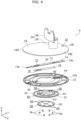
- FIG. 4 is an exploded perspective view of stand 6 according to the embodiment in a disassembled state.
- stand 6 includes base 18, stand neck 20, holding cover 22, suction member 24, holder 26, slip sheet 28, and slide valve 30. The following describes the structural components of stand 6.
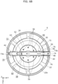
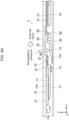
- FIG. 5A is a cross-sectional view of stand 6 according to the embodiment cut along V-V line in FIG. 2 when slide valve 30 is in the closed position.
- FIG. 5B is a cross-sectional view of stand 6 according to the embodiment cut along V-V line in FIG. 2 when slide valve 30 is in the opened position.
- base 18, which is a base placed on placement surface 16a (see FIG. 1 ), comprises, for example, a metal plate having a circular shape in a plan view of the XY plane.
- Base 18 includes insertion hole 32 at end portion 18c of base 18 at the back side in the depth direction. Stated differently, insertion hole 32 is located in a displaced position at the back side of base 18 in the depth direction with respect to the diameter center of base 18. Knob 74 of slide valve 30 (to be described later) is inserted in insertion hole 32 in a manner that knob 74 is movable in the depth direction.
- lower surface 18a of base 18 Located in lower surface 18a of base 18 are a plurality of screw holes (not illustrated) into which a plurality of screws (see FIG. 3 and FIG. 4 ) are screwed.
- lower surface 18a of base 18 is the surface that faces placement surface 16a.
- lower surface 18a of base 18 includes recessed portion 34 (to be described later).
- Stand neck 20 is a member for supporting device body 4 (see FIG. 1 ).
- stand neck 20 includes column portion 36 and bracket 38.
- Column portion 36 which has a circular cylindrical shape, for example, is vertically provided on upper surface 18b of base 18 (the surface opposite to lower surface 18a).
- Column portion 36 is located on upper surface 18b of base 18, between the diameter center of base 18 and insertion hole 32.
- Bracket 38 which is located on the upper end portion of column portion 36, is attached to rear cabinet 14 of device body 4.
- stand neck 20 may have a swiveling function of adjusting the orientation of display surface 8a of device body 4 with respect to base 18 within a predetermined range of angles.
- bracket 38 is configured to rotate about the central axis of column portion 36 within the predetermined range of angles with respect to column portion 36.
- FIG. 6A is a plan view of stand 6 according to the embodiment when slide valve 30 is in the closed position and base 18 and stand neck 20 are not illustrated.
- FIG. 6B is a plan view of stand 6 according to the embodiment when slide valve 30 is in the opened position and base 18 and stand neck 20 are not illustrated.
- Holding cover 22 which is a member for keeping slide valve 30 slidable along the depth direction, comprises, for example, resin. As shown in FIG. 4 through FIG. 5B , holding cover 22 has, for example, a circular ring shape in a plan view of the XY plane. Holding cover 22 is located to face lower surface 18a of base 18. Holding cover 22 includes, at its central portion, opening portion 40 having a circular shape for attaching suction member 24 to lower surface 18a of base 18.
- holding cover 22 includes a plurality of non-slip rubber feet 42 attached on lower surface 22a of holding cover 22. Note that lower surface 22a of holding cover 22 is the surface that faces placement surface 16a.
- groove portion 44 that extends along the depth direction is located in upper surface 22b of holding cover 22 (the surface opposite to lower surface 22a). Groove portion 44 extends from the inner periphery to the outer periphery of holding cover 22. Slide valve 30 is located in groove portion 44 in a manner that slide valve 30 is slidable along the longitudinal direction (the Y axis direction) of groove portion 44.
- groove portion 44 includes a pair of stoppers 46 for regulating the range in which slide valve 30 slides.
- a pair of stoppers 46 are located spaced apart from each other along the longitudinal direction of groove portion 44.
- groove portion 44 further includes a pair of protruded portions 48.
- a pair of protruded portions 48 are located to face each other in the lateral direction (the X axis direction) of groove portion 44.
- a pair of protruded portions 48 and a pair of engagement portions 76 of slide valve 30 are included in engagement mechanism 50 for providing tactile feedback in an operation of sliding slide valve 30.
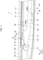
- FIG. 7 is a cross-sectional perspective view of an enlarged part of stand 6 shown in FIG. 5B .
- Suction member 24 is a member that adheres to placement surface 16a by suction, thereby preventing electronic device 2 (see FIG. 1 ) from falling over.
- Suction member 24 has a sheet shape in the thickness, for example, of some 1 mm to a few mm.
- Suction member 24 comprises, for example, an elastic material such as silicon, urethane, and rubber. As shown in FIG. 4 through FIG. 5B , suction member 24 includes attachment portion 52 and suction portion 54.
- Attachment portion 52 has, for example, a circular shape in a plan view of the XY plane. As shown in FIG. 5A through FIG. 6B , attachment portion 52 is inserted in opening portion 40 of holding cover 22 to face lower surface 18a of base 18. More specifically, attachment portion 52 is supported by being sandwiched between lower surface 18a of base and holder 26. As shown in FIG. 5B , air admission opening 62 that is in fluid communication with opening portion 72 of slide valve 30 (to be described later) is located between the outer periphery of attachment portion 52 and the outer periphery of opening portion 40 of holding cover 22.
- attachment portion 52 includes a plurality of holes 58 into which a plurality of screws 56 are inserted.
- a plurality of holes 58 are located at intervals in a circumferential direction of attachment portion 52 in one-to-one correspondence with a plurality of screw holes located in lower surface 18a of base 18.
- Attachment portion 52 further includes ventilation hole 60 that penetrates through attachment portion 52 in the thickness direction of attachment portion 52 (the Z axis direction). Ventilation hole 60 has, for example, a circular shape in a plan view of the XY plane.
- ventilation hole 60 is located to face recessed portion 34 located in lower surface 18a of base 18.
- groove portion 63 that extends along the depth direction is located in upper surface of attachment portion 52 (the surface that faces lower surface 18a of base 18). Groove portion 63 extends continuously from groove portion 44 of holding cover 22. Slide valve 30 is located in groove portion 63 in a manner that slide valve 30 is slidable along the longitudinal direction (the Y axis direction) of groove portion 63. Also, ventilation hole 60 described above is located in groove portion 63.
- suction portion 54 extends from the outer periphery of attachment portion 52 in an outer radial direction in a skirt (umbrella) shape. As shown in FIG. 3 , located on the lower surface of suction portion 54 is suction surface 54a having, for example, a circular ring shape in a plan view of the XY plane.
- Holder 26 is a member for attaching suction member 24 to lower surface 18a of base 18.
- holder 26 has, for example, a circular shape in a plan view of the XY plane.
- Holder 26 includes a plurality of holes 66 into which a plurality of screws 56 are inserted.
- a plurality of holes 66 are located at intervals in a circumferential direction of holder 26 in one-to-one correspondence with a plurality of screw holes located in lower surface 18a of base 18.
- holder 26 includes ventilation hole 68 that is in fluid communication with ventilation hole 60 of attachment portion 52 of suction member 24.
- Ventilation hole 68 has, for example, a circular shape in a plan view of the XY plane.
- the diameter of ventilation hole 68 is larger than the diameter of ventilation hole 60 of attachment portion 52.
- the diameter of ventilation hole 68 may be the same as the diameter of ventilation hole 60 of attachment portion 52.
- ventilation hole 68 may have a tapered shape in which its diameter becomes larger or smaller toward ventilation hole 60 of attachment portion 52.
- a plurality of screws 56 are screwed into a plurality of screw holes of base 18 through a plurality of holes 66 of holder 26 and a plurality of holes 58 of attachment portion 52 of suction member 24. This enables attachment portion 52 of suction member 24 to be attached to lower surface 18a of base 18 in holder 26.
- Slip sheet 28 is intended for improving the slip property of slide valve 30 to suction member 24.
- Slip sheet 28 is a sheet having a long-length shape in the thickness, for example, of 1 mm or below.
- Slip sheet 28 comprises, for example, a slippery material such as polyethene terephthalate.
- slip sheet 28 includes opening portion 70 that extends in the longitudinal direction (the Y axis direction) of slip sheet 28.
- slip sheet 28 is attached to groove portion 63 of attachment portion 52 of suction member 24 and groove portion 44 of holding cover 22. Slip sheet 28 is located between slide valve 30 and suction member 24. Slip sheet 28 with this configuration enables slide valve 30 to be located without contact with at least attachment portion 52 of suction member 24. Opening portion 70 of slip sheet 28 is in fluid communication with ventilation hole 60 of suction member 24 and air admission opening 62.
- a protruded portion (not illustrated) having a circular ring shape is located in the peripheral portion of ventilation hole 60 of attachment portion 52 of suction member 24.
- This protruded portion presses the lower surface of slide valve 30 (the surface that faces suction member 24) via opening portion 70 of slip sheet 28.
- This configuration enables slide valve 30 to slide between the closed position and the opened position to be described later, pressing the protruded portion. Consequently, ventilation hole 60 of suction member 24 is closed when slide valve 30 is in the closed position.
- This configuration also enables slide valve 30 to smoothly slide without running on the protruded portion when slide valve 30 slides from the opened position to the closed position.
- Slide valve 30 is a changeover valve for letting in or stop the air into gap 64 (see FIG. 8A and FIG. 8B to be described later).
- slide valve 30 comprises, for example, resin. Slide valve 30 is located between base 18 and suction member 24. As shown in FIG. 4 , FIG. 6A and FIG. 6B , slide valve 30 includes valve body 73 and knob 74.
- Valve body 73 has a long thin plate shape in the thickness of, for example, some 1 mm to 2 mm. Valve body 73 is located in groove portion 44 of holding cover 22 and in groove portion 63 of attachment portion 52 of suction member 24 via slip sheet 28.
- valve body 73 slides between the closed position and the opened position along lower surface 18a of base 18 in the depth direction.
- the closed position is a position at which valve body 73 closes ventilation hole 60 of suction member 24 to interrupt the flow of air into gap 64 (see FIG. 8A and FIG. 8B to be described later).
- the opened position is a position at which valve body 73 opens ventilation hole 60 of suction member 24 to let the air flow into gap 64.
- Valve body 73 includes opening portion 72 that extends in the longitudinal direction (the Y axis direction) of valve body 73. As shown in FIG. 5B , FIG. 6B , and FIG. 7 , when valve body 73 is in the opened position, opening portion 72 is in fluid communication with ventilation hole 60 of suction member 24 by being located to overlap ventilation hole 60 of suction member 24 in a plan view of the XY plane. As shown in FIG. 5A and FIG. 6A , when valve body 73 is in the closed position, opening portion 72 is not in fluid communication with ventilation hole 60 of suction member 24 by being located not to overlap ventilation hole 60 of suction member 24 in a plan view of the XY plane.
- valve body 73 when valve body 73 is in the closed position, end portion 73a of valve body 73 at the front side in the depth direction is located to be exposed to end portion 18d of base 18 at the front side in the depth direction.
- rib 78 having a substantially rectangular frame shape in a plan view of the XY plane is provided on the lower surface of valve body 73. Rib 78 is located between a pair of stoppers 46 of holding cover 22 in the depth direction.
- rib 78 of valve body 73 comes into contact with one of a pair of stoppers 46 of holding cover 22, thereby regulating valve body 73 not to slide beyond the opened position.
- rib 78 of valve body 73 comes into contact with the other of a pair of stoppers 46 of holding cover 22, thereby regulating valve body 73 not to slide beyond the closed position. This regulates valve body 73 to slide within the range between the closed position and the opened position.
- a pair of engagement portions 76 are located at both ends of valve body 73 in the lateral direction (the X axis direction).
- each of a pair of engagement portions 76 is engaged in a pair of protruded portions 48 of holding cover 22. This provides a user with tactile feedback when the user slides slide valve 30 from the opened position to the closed position.
- each of a pair of engagement portions 76 elastically bends to be released from the engagement with a pair of protruded portions 48 of holding cover 22. This provides the user with tactile feedback when the user slides slide valve 30 from the closed position to the opened position.
- Knob 74 is provided at end portion 73b of valve body 73 at the back side in the depth direction. Knob 74 protrudes from the upper surface of valve body 73 toward base 18. Knob 74 is inserted in insertion hole 32 of base 18 in a manner that knob 74 is movable in the depth direction. Stated differently, knob 74 protrudes from upper surface 18b of base 18 in an upward direction through insertion hole 32.
- the user can slide valve body 73 from the closed position to the opened position by moving knob 74 in the direction indicated by arrow P shown in FIG. 5A .
- the user can also slide valve body 73 from the opened position to the closed position by moving knob 74 in the direction indicated by arrow Q shown in FIG. 5B .
- FIG. 8A is a diagram for explaining an operation of stand 6 according to the embodiment when slide valve 30 is in the closed position.
- FIG. 8B is a diagram for explaining an operation of stand 6 according to the embodiment when slide valve 30 is in the opened position.
- gap 64 is created between the lower surface of holder 26 and placement surface 16a and between the inner portion of suction surface 54a of suction portion 54 and placement surface 16a. Stated differently, gap 64 is a space enclosed by placement surface 16a, the lower surface of holder 26, suction surface 54a of suction portion 54, ventilation hole 60 of attachment portion 52, and slide valve 30. At this time, suction portion 54 of suction member 24 is pressed against placement surface 16a by the weight of stand 6, as a result of which the volume of gap 64 becomes minimum.
- suction portion 54 works, which is an ability to return to the original shape.
- the force that presses suction portion 54 against placement surface 16a is, however, greater than such elastic resilience.
- suction portion 54 of suction member 24 remains in a state in which the volume of gap 64 is minimum, and thus is not deformed by the elastic resilience. Consequently, no negative pressure is generated in gap 64, meaning that the outer portion of suction surface 54a of suction portion 54 does not adhere to placement surface 16a by suction.
- Suction portion 54 extends in a skirt shape from the outer periphery of attachment portion 52 in an outer radial direction. For this reason, even when placement surface 16a has asperities, suction portion 54 can deform to fit the asperities of placement surface 16a. This brings the outer portion of suction surface 54a of suction portion 54 into intimate contact with placement surface 16a.
- stand 6 in the foregoing state is under an external force acting in a direction away from placement surface 16a when slide valve 30 is in the closed position as shown in FIG. 8A .
- example cases where stand 6 is under such an external force include: a) in the event of an earthquake; b) when the user improperly moves placement table 16; and c) when the user's body bumps into device body 4.
- suction portion 54 of suction member 24 elastically deforms in a direction away from placement surface 16a.
- the volume of gap 64 increases to generate negative pressure in gap 64.
- suction portion 54 to be pressed against placement surface 16a by atmospheric pressure, as a result of which the outer portion of suction surface 54a of suction portion 54 adheres to placement surface 16a by suction. This consequently prevents electronic device 2 from falling over.
- knob 74 the user may perform an operation described below to slide valve body 73.
- the user can slide valve body 73 from the closed position to the opened position, when slide valve 30 is in the closed position, by pressing end portion 73a of valve body 73 into the back side in the depth direction (the positive side of the Y axis direction). Meanwhile, the user can slide valve body 73 from the opened position to the closed position, when slide valve 30 is in the opened position, by drawing end portion 73a of valve body 73 toward the front side in the depth direction (the negative side of the Y axis direction) using a hook, etc.
- the configuration that eliminates knob 74 enhances the design of stand 6, for example, because there is no knob 74 protruding from upper surface 18b of base 18. In this case, the user uses end portion 73a of valve body 73 to slide valve body 73.
- electronic device 2 is an electronic device placed on placement surface 16a.
- Electronic device 2 includes: device body 4; and stand 6 that is placed on placement surface 16a and supports device body 4.
- Stand 6 includes: base 18 including lower surface 18a that faces placement surface 16a; suction member 24 that is elastic, faces lower surface 18a of base 18, includes suction surface 54a that adheres to placement surface 16a by negative pressure generated in gap 64 between placement surface 16a and suction surface 54a, and includes ventilation hole 60 that is in fluid communication with gap 64; and slide valve 30 that is located between base 18 and suction member 24 and slides between an opened position and a closed position along lower surface 18a of base 18, the opened position being a position at which ventilation hole 60 is opened to let air into gap 64, the closed position being a position at which ventilation hole 60 is closed to interrupt air into gap 64.
- suction member 24 When slide valve 30 is in the closed position, suction member 24 generates the negative pressure in gap 64 by elastically deforming in a direction away from placement surface 16a when the stand is under an external force acting in the
- slide valve 30 slides between the opened position and the closed position along lower surface 18a of base 18.
- This configuration reduces the thickness (the dimension in the Z axis direction) of the valve mechanism for opening and closing ventilation hole 60 of suction member 24. This consequently reduces the thickness of stand 6.
- stand 6 further includes slip sheet 28 located between slide valve 30 and suction member 24, slip sheet 28 having a slippery property.
- Slide valve 30 slides between the opened position and the closed position by sliding on slip sheet 28.
- This configuration reduces the friction between slide valve 30 and slip sheet 28, thus enabling slide valve 30 to smoothly slide between the opened position and the closed position.
- slide valve 30 includes: valve body 73 that slides between the opened position and the closed position along a depth direction of electronic device 2; and knob 74 used to slide valve body 73, knob 74 being provided at end portion 73b of valve body 73 at a back side in the depth direction.
- base 18 includes insertion hole 32 into which knob 74 is inserted in a manner that knob 74 is movable in the depth direction, insertion hole 32 being located at end portion 18c of base 18 at the back side in the depth direction.
- end portion 73a of valve body 73 at a front side in the depth direction is located to be exposed to end portion 18d of base 18 at the front side in the depth direction when valve body 73 is in the closed position.
- This configuration enables the user to easily slide valve body 73 from the closed position to the opened position by pressing in end portion 73a of valve body 73 at the front side in the depth direction.
- valve body 73 includes opening portion 72. Opening portion 72 is in fluid communication with ventilation hole 60 when valve body 73 is in the opened position, and is not in fluid communication with ventilation hole 60 when valve body 73 is in the closed position.
- recessed portion 34 is located in lower surface 18a of base 18, recessed portion 34 serving as a channel through which air flows into gap 64 via opening portion 72 and ventilation hole 60, when valve body 73 is in the opened position.
- recessed portion 34 of base 18 serves as a channel through which the air flows, thereby enabling an efficient flow of air into gap 64.
- stand 6 further includes engagement mechanism 50 for providing tactile feedback when sliding slide valve 30.
- This provides the user with tactile feedback when the user slides slide valve 30, thus enabling the user to have an intuitive feeling that the user has slid slide valve 30 from the closed position to the opened position (or from the opened position to the closed position).
- electronic device 2 is an image display device
- device body 4 includes display panel 8 for image display.
- This configuration reduces the thickness of stand 6 of the image display device.
- stand 6 is placed on placement surface 16a and supports device body 4.
- Stand 6 includes: base 18 including lower surface 18a that faces placement surface 16a; suction member 24 that is elastic, faces lower surface 18a of base 18, includes suction surface 54a that adheres to placement surface 16a by negative pressure generated in gap 64 between placement surface 16a and suction surface 54a, and includes ventilation hole 60 that is in fluid communication with gap 64; and slide valve 30 that is located between base 18 and suction member 24 and slides between an opened position and a closed position along lower surface 18a of base 18, the opened position being a position at which ventilation hole 60 is opened to let air into gap 64, the closed position being a position at which ventilation hole 60 is closed to interrupt air into gap 64.
- suction member 24 When slide valve 30 in the closed position, suction member 24 generates the negative pressure in gap 64 by elastically deforming in a direction away from placement surface 16a when stand 6 is under an external force acting in the direction away from placement surface 16a.
- slide valve 30 slides between the opened position and the closed position along lower surface 18a of base 18. This configuration thus reduces the thickness of the valve mechanism for opening and closing ventilation hole 60 of suction member 24. This consequently reduces the thickness of stand 6.
- electronic device 2 is described as a liquid crystal television receiver, but the present disclosure is not limited to this.
- electronic device 2 may be, for example, a liquid crystal display for a personal computer, an organic electro luminescence (EL) display, or other various image display devices.
- electronic device 2 may be, for example, a speaker, an electrical fan, an electrical heater, a lighting device (electrical lamp), or other various devices.
- suction member 24 has a circular shape in a plan view of the XY plane, but the present disclosure is not limited to this. Suction member 24 may thus have, for example, a polygonal shape or an oval shape in a plan view of the XY plane.
- insertion hole 32 is provided for inserting knob 74 to base 18, but the present disclosure is not limited to this configuration.
- Knob 74 may thus be inserted, for example, to a notch portion provided on the outer periphery of base 18.
- end portion 73a of valve body 73 at the front side in the depth direction is located to be exposed to end portion 18d of base 18 at the front side in the depth direction when valve body 73 is in the closed position, but the present disclosure is not limited to this configuration. End portion 73a of valve body 73 may thus be located to be exposed to end portion 18d of base 18 when valve body 73 is in the opened position.
- the present disclosure is applicable to an electronic device having a stand. More specifically, the present disclosure is applicable, for example, to an image display device such as a liquid crystal television receiver.
Landscapes
- Engineering & Computer Science (AREA)
- General Engineering & Computer Science (AREA)
- Mechanical Engineering (AREA)
- Multimedia (AREA)
- Signal Processing (AREA)
- Microelectronics & Electronic Packaging (AREA)
- Hooks, Suction Cups, And Attachment By Adhesive Means (AREA)
- Casings For Electric Apparatus (AREA)
- Devices For Indicating Variable Information By Combining Individual Elements (AREA)
Claims (10)
- Ständer (6), der auf einer Platzierungsoberfläche (16a) platziert ist und dazu ausgestaltet ist, einen Vorrichtungskörper (4) einer elektronischen Vorrichtung (2) zu tragen, wobei der Ständer (6) umfasst:eine Basis (18), die eine untere Oberfläche (18a) umfasst, die der Platzierungsoberfläche (16a) zugewandt ist;ein Saugelement (24), das elastisch ist, der unteren Oberfläche (18a) der Basis (18) zugewandt ist, eine Saugoberfläche (54a) umfasst, die durch Unterdruck, der in einer Lücke (64) zwischen der Platzierungsoberfläche (16a) und der Saugoberfläche (54a) erzeugt wird, an der Platzierungsoberfläche (16a) haftet, und ein Lüftungsloch (60) umfasst, das in Fluidverbindung mit der Lücke (64) steht; undein Schieberventil (30), das sich zwischen der Basis (18) und dem Saugelement (24) befindet und sich entlang der unteren Oberfläche (18a) der Basis (18) zwischen einer geöffneten Position und einer geschlossenen Position verschiebt, wobei die geöffnete Position eine Position ist, an der das Lüftungsloch (60) geöffnet ist, um Luft in die Lücke (64) zu lassen, wobei die geschlossene Position eine Position ist, an der das Lüftungsloch (60) geschlossen ist, um Luft in die Lücke (64) zu unterbrechen, undwenn das Schieberventil (30) sich in der geschlossenen Position befindet, das Saugelement (24) den Unterdruck in der Lücke (64) durch elastisches Verformen in einer Richtung weg von der Platzierungsoberfläche (16a) erzeugt, wenn der Ständer (6) einer externen Kraft unterliegt, die in der Richtung weg von der Platzierungsoberfläche (16a) wirkt.
- Ständer (6) nach Anspruch 1,der ferner eine Rutschfolie (28) umfasst, die sich zwischen dem Schieberventil (30) und dem Saugelement (24) befindet, wobei die Rutschfolie (28) eine rutschige Eigenschaft aufweist, unddas Schieberventil (30) sich durch Verschieben auf der Rutschfolie (28) zwischen der geöffneten Position und der geschlossenen Position verschiebt.
- Ständer (6) nach Anspruch 1 oder 2,
wobei das Schieberventil (30) umfasst:einen Ventilkörper (73), der sich entlang einer Tiefenrichtung der elektronischen Vorrichtung (2) zwischen der geöffneten Position und der geschlossenen Position verschiebt,wobei die elektronische Vorrichtung (2) bei der Verwendung auf der Platzierungsoberfläche (16a) platziert ist und den Vorrichtungskörper (4) umfasst; undeinen Knauf (74), der zum Verschieben des Ventilkörpers (73) verwendet wird, wobei der Knauf (74) an einem Endabschnitt (73a) des Ventilkörpers (73) an einer Hinterseite in der Tiefenrichtung bereitgestellt ist. - Ständer (6) nach Anspruch 3,
wobei die Basis (18) ein Einsetzloch (32) umfasst, in das der Knauf (74) derart eingesetzt ist, dass der Knauf (74) in der Tiefenrichtung beweglich ist, wobei das Einsetzloch (32) sich an einem Endabschnitt (18c) der Basis (18) an der Hinterseite in der Tiefenrichtung befindet. - Ständer (6) nach Anspruch 3 oder 4,
wobei ein Endabschnitt (73a) des Ventilkörpers (73) sich an einer Vorderseite in der Tiefenrichtung befindet, um für einen Endabschnitt (18d) der Basis (18) an der Vorderseite in der Tiefenrichtung freizuliegen, wenn der Ventilkörper (73) sich in einer von der geöffneten Position und der geschlossenen Position befindet. - Ständer (6) nach einem der Ansprüche 3 bis 5,wobei der Ventilkörper (73) einen Öffnungsabschnitt (72) umfasst, undder Öffnungsabschnitt (72) in Fluidverbindung mit dem Lüftungsloch (60) steht, wenn der Ventilkörper (73) sich in der geöffneten Position befindet, und nicht in Fluidverbindung mit dem Lüftungsloch (60) steht, wenn der Ventilkörper (73) sich in der geschlossenen Position befindet.
- Ständer (6) nach Anspruch 6,
wobei ein vertiefter Abschnitt (34) sich in der unteren Oberfläche (18a) der Basis (18) befindet, wobei der vertiefte Abschnitt (34) als ein Kanal dient, durch den Luft über den Öffnungsabschnitt (72) und das Lüftungsloch (60) in die Lücke (64) strömt, wenn der Ventilkörper (73) sich in der geöffneten Position befindet. - Ständer (6) nach einem der Ansprüche 3 bis 7,
der ferner einen Eingriffsmechanismus (50) zum Bereitstellen von Berührungsrückmeldung beim Verschieben des Schieberventils (30) umfasst. - Elektronische Vorrichtung (2), die auf einer Platzierungsoberfläche (16a) platziert ist, wobei die elektronische Vorrichtung (2) umfasst:einen Vorrichtungskörper (4); undeinen Ständer (6) nach einem der Ansprüche 1 bis 8, der auf der Platzierungsoberfläche (16a) platziert ist und den Vorrichtungskörper (4) trägt.
- Elektronische Vorrichtung (2) nach Anspruch 9,wobei die elektronische Vorrichtung (2) eine Bildanzeigevorrichtung ist, undder Vorrichtungskörper (4) ein Anzeigefeld (8) zur Bildanzeige umfasst.
Applications Claiming Priority (2)
| Application Number | Priority Date | Filing Date | Title |
|---|---|---|---|
| JP2019133485 | 2019-07-19 | ||
| PCT/JP2020/004706 WO2021014664A1 (ja) | 2019-07-19 | 2020-02-07 | 電子機器及びスタンド |
Publications (3)
| Publication Number | Publication Date |
|---|---|
| EP4002963A1 EP4002963A1 (de) | 2022-05-25 |
| EP4002963A4 EP4002963A4 (de) | 2022-09-14 |
| EP4002963B1 true EP4002963B1 (de) | 2024-11-13 |
Family
ID=74192659
Family Applications (1)
| Application Number | Title | Priority Date | Filing Date |
|---|---|---|---|
| EP20843277.3A Active EP4002963B1 (de) | 2019-07-19 | 2020-02-07 | Elektronisches instrument und ständer |
Country Status (4)
| Country | Link |
|---|---|
| US (1) | US11672090B2 (de) |
| EP (1) | EP4002963B1 (de) |
| JP (1) | JP7002029B2 (de) |
| WO (1) | WO2021014664A1 (de) |
Families Citing this family (2)
| Publication number | Priority date | Publication date | Assignee | Title |
|---|---|---|---|---|
| KR20250028236A (ko) * | 2022-07-05 | 2025-02-28 | 엘지전자 주식회사 | 지지 장치 및 이를 구비한 디스플레이 장치 |
| CN120898188A (zh) * | 2023-04-11 | 2025-11-04 | 索尼互动娱乐股份有限公司 | 支架设备 |
Family Cites Families (14)
| Publication number | Priority date | Publication date | Assignee | Title |
|---|---|---|---|---|
| JPH06263106A (ja) | 1993-03-09 | 1994-09-20 | Ishida Co Ltd | 箱詰め装置 |
| JP2008089088A (ja) * | 2006-10-02 | 2008-04-17 | Sony Corp | 連結構造およびジョイント |
| US7975971B2 (en) * | 2006-11-15 | 2011-07-12 | Carnevali Jeffrey D | Suction cup device |
| US7578487B2 (en) | 2006-11-21 | 2009-08-25 | Sony Corporation | Music stand and article retaining apparatus |
| JP5239298B2 (ja) | 2007-11-05 | 2013-07-17 | セイコーエプソン株式会社 | ロール紙供給機構およびロール紙プリンタ |
| JP2011153652A (ja) | 2010-01-26 | 2011-08-11 | Ntt Facilities Inc | 固定装置および固定構造 |
| CN102644655B (zh) * | 2011-02-18 | 2016-08-03 | 富泰华工业(深圳)有限公司 | 连接装置及带有连接装置的支架 |
| US20130248665A1 (en) * | 2012-03-24 | 2013-09-26 | Peter Koklamanis | Television base and television safety device |
| CN104921574A (zh) * | 2014-03-21 | 2015-09-23 | 蓝永辉 | 贴附式壁面支持结构 |
| JP6489575B2 (ja) * | 2014-09-25 | 2019-03-27 | 株式会社貝印刃物開発センター | 吸盤装置 |
| CN105979046A (zh) * | 2016-06-20 | 2016-09-28 | 罗建华 | 飞机上使用的万向手机支架 |
| US11272627B2 (en) * | 2016-11-28 | 2022-03-08 | Panasonic Intellectual Property Management Co., Ltd. | Electronic device and stand |
| CN207334187U (zh) * | 2017-10-25 | 2018-05-08 | 深圳市智高翔科技发展有限公司 | 一种基于负压吸附的支撑装置 |
| US20200041828A1 (en) * | 2018-08-01 | 2020-02-06 | Sharp Kabushiki Kaisha | Method of removing panel from suction surface, method of producing display panel, and panel catcher |
-
2020
- 2020-02-07 EP EP20843277.3A patent/EP4002963B1/de active Active
- 2020-02-07 US US17/423,763 patent/US11672090B2/en active Active
- 2020-02-07 JP JP2021505437A patent/JP7002029B2/ja active Active
- 2020-02-07 WO PCT/JP2020/004706 patent/WO2021014664A1/ja not_active Ceased
Also Published As
| Publication number | Publication date |
|---|---|
| EP4002963A4 (de) | 2022-09-14 |
| JP7002029B2 (ja) | 2022-01-20 |
| WO2021014664A1 (ja) | 2021-01-28 |
| EP4002963A1 (de) | 2022-05-25 |
| US11672090B2 (en) | 2023-06-06 |
| US20220124927A1 (en) | 2022-04-21 |
| JPWO2021014664A1 (ja) | 2021-09-13 |
Similar Documents
| Publication | Publication Date | Title |
|---|---|---|
| KR102168145B1 (ko) | 회전 컴포넌트 부착용 힌지 기구 | |
| US9937690B2 (en) | Two-stage application device for installing screen protectors and kit comprising the application device | |
| US20170090522A1 (en) | Portable electronic device | |
| EP3306172B1 (de) | Anzeigevorrichtung | |
| US11272627B2 (en) | Electronic device and stand | |
| EP3345667B1 (de) | Ständer, haltestruktur und vorrichtung | |
| US11672090B2 (en) | Electronic device and stand | |
| KR200476134Y1 (ko) | 차량용 모바일 기기의 장착 장치 | |
| US8976522B2 (en) | Portable electronic device and docking device thereof | |
| US12623612B2 (en) | Windshield mount for personal electronic device | |
| EP3406958B1 (de) | Scharniervorrichtung und anzeigevorrichtung mit einer scharniervorrichtung unter verwendung einer gleitposition | |
| US9251973B2 (en) | Push button switch and electronic apparatus using same | |
| US20170068373A1 (en) | Stand alone input device | |
| KR20180062872A (ko) | 휴대기기용 카메라 덮개 | |
| CN102644835A (zh) | 脚架 | |
| KR100296283B1 (ko) | 디스플레이 모니터의 높이조절장치 | |
| JP4834692B2 (ja) | 表示ユニットを備えた電子機器 | |
| US20130168424A1 (en) | Apparatus for holding portable devices | |
| TWI386584B (zh) | 角度調整機構 | |
| CN112543263A (zh) | 摄像头及电子装置 | |
| KR100587350B1 (ko) | 평판형 영상표시기기의 높이조절 받침대 구조 | |
| KR20160132640A (ko) | 휴대용 단말기 거치대 | |
| KR20080019426A (ko) | 도킹 스테이션과 이를 가지는 휴대용 컴퓨터 | |
| KR100568219B1 (ko) | 디스플레이 장치 | |
| AU2012382071B2 (en) | Uninterruptible power supply having adjustable interface |
Legal Events
| Date | Code | Title | Description |
|---|---|---|---|
| STAA | Information on the status of an ep patent application or granted ep patent |
Free format text: STATUS: THE INTERNATIONAL PUBLICATION HAS BEEN MADE |
|
| PUAI | Public reference made under article 153(3) epc to a published international application that has entered the european phase |
Free format text: ORIGINAL CODE: 0009012 |
|
| STAA | Information on the status of an ep patent application or granted ep patent |
Free format text: STATUS: REQUEST FOR EXAMINATION WAS MADE |
|
| 17P | Request for examination filed |
Effective date: 20211223 |
|
| AK | Designated contracting states |
Kind code of ref document: A1 Designated state(s): AL AT BE BG CH CY CZ DE DK EE ES FI FR GB GR HR HU IE IS IT LI LT LU LV MC MK MT NL NO PL PT RO RS SE SI SK SM TR |
|
| A4 | Supplementary search report drawn up and despatched |
Effective date: 20220812 |
|
| RIC1 | Information provided on ipc code assigned before grant |
Ipc: H04N 5/64 20060101ALI20220808BHEP Ipc: H05K 5/02 20060101AFI20220808BHEP |
|
| DAV | Request for validation of the european patent (deleted) | ||
| DAX | Request for extension of the european patent (deleted) | ||
| GRAP | Despatch of communication of intention to grant a patent |
Free format text: ORIGINAL CODE: EPIDOSNIGR1 |
|
| STAA | Information on the status of an ep patent application or granted ep patent |
Free format text: STATUS: GRANT OF PATENT IS INTENDED |
|
| INTG | Intention to grant announced |
Effective date: 20240712 |
|
| GRAS | Grant fee paid |
Free format text: ORIGINAL CODE: EPIDOSNIGR3 |
|
| GRAA | (expected) grant |
Free format text: ORIGINAL CODE: 0009210 |
|
| STAA | Information on the status of an ep patent application or granted ep patent |
Free format text: STATUS: THE PATENT HAS BEEN GRANTED |
|
| AK | Designated contracting states |
Kind code of ref document: B1 Designated state(s): AL AT BE BG CH CY CZ DE DK EE ES FI FR GB GR HR HU IE IS IT LI LT LU LV MC MK MT NL NO PL PT RO RS SE SI SK SM TR |
|
| REG | Reference to a national code |
Ref country code: GB Ref legal event code: FG4D |
|
| REG | Reference to a national code |
Ref country code: CH Ref legal event code: EP |
|
| REG | Reference to a national code |
Ref country code: DE Ref legal event code: R096 Ref document number: 602020041440 Country of ref document: DE |
|
| REG | Reference to a national code |
Ref country code: IE Ref legal event code: FG4D |
|
| REG | Reference to a national code |
Ref country code: LT Ref legal event code: MG9D |
|
| REG | Reference to a national code |
Ref country code: NL Ref legal event code: MP Effective date: 20241113 |
|
| PG25 | Lapsed in a contracting state [announced via postgrant information from national office to epo] |
Ref country code: PT Free format text: LAPSE BECAUSE OF FAILURE TO SUBMIT A TRANSLATION OF THE DESCRIPTION OR TO PAY THE FEE WITHIN THE PRESCRIBED TIME-LIMIT Effective date: 20250313 Ref country code: IS Free format text: LAPSE BECAUSE OF FAILURE TO SUBMIT A TRANSLATION OF THE DESCRIPTION OR TO PAY THE FEE WITHIN THE PRESCRIBED TIME-LIMIT Effective date: 20250313 Ref country code: HR Free format text: LAPSE BECAUSE OF FAILURE TO SUBMIT A TRANSLATION OF THE DESCRIPTION OR TO PAY THE FEE WITHIN THE PRESCRIBED TIME-LIMIT Effective date: 20241113 |
|
| PG25 | Lapsed in a contracting state [announced via postgrant information from national office to epo] |
Ref country code: FI Free format text: LAPSE BECAUSE OF FAILURE TO SUBMIT A TRANSLATION OF THE DESCRIPTION OR TO PAY THE FEE WITHIN THE PRESCRIBED TIME-LIMIT Effective date: 20241113 Ref country code: NL Free format text: LAPSE BECAUSE OF FAILURE TO SUBMIT A TRANSLATION OF THE DESCRIPTION OR TO PAY THE FEE WITHIN THE PRESCRIBED TIME-LIMIT Effective date: 20241113 |
|
| REG | Reference to a national code |
Ref country code: AT Ref legal event code: MK05 Ref document number: 1742641 Country of ref document: AT Kind code of ref document: T Effective date: 20241113 |
|
| PG25 | Lapsed in a contracting state [announced via postgrant information from national office to epo] |
Ref country code: BG Free format text: LAPSE BECAUSE OF FAILURE TO SUBMIT A TRANSLATION OF THE DESCRIPTION OR TO PAY THE FEE WITHIN THE PRESCRIBED TIME-LIMIT Effective date: 20241113 |
|
| PG25 | Lapsed in a contracting state [announced via postgrant information from national office to epo] |
Ref country code: ES Free format text: LAPSE BECAUSE OF FAILURE TO SUBMIT A TRANSLATION OF THE DESCRIPTION OR TO PAY THE FEE WITHIN THE PRESCRIBED TIME-LIMIT Effective date: 20241113 |
|
| PG25 | Lapsed in a contracting state [announced via postgrant information from national office to epo] |
Ref country code: NO Free format text: LAPSE BECAUSE OF FAILURE TO SUBMIT A TRANSLATION OF THE DESCRIPTION OR TO PAY THE FEE WITHIN THE PRESCRIBED TIME-LIMIT Effective date: 20250213 |
|
| PG25 | Lapsed in a contracting state [announced via postgrant information from national office to epo] |
Ref country code: LV Free format text: LAPSE BECAUSE OF FAILURE TO SUBMIT A TRANSLATION OF THE DESCRIPTION OR TO PAY THE FEE WITHIN THE PRESCRIBED TIME-LIMIT Effective date: 20241113 Ref country code: GR Free format text: LAPSE BECAUSE OF FAILURE TO SUBMIT A TRANSLATION OF THE DESCRIPTION OR TO PAY THE FEE WITHIN THE PRESCRIBED TIME-LIMIT Effective date: 20250214 Ref country code: AT Free format text: LAPSE BECAUSE OF FAILURE TO SUBMIT A TRANSLATION OF THE DESCRIPTION OR TO PAY THE FEE WITHIN THE PRESCRIBED TIME-LIMIT Effective date: 20241113 |
|
| PG25 | Lapsed in a contracting state [announced via postgrant information from national office to epo] |
Ref country code: PL Free format text: LAPSE BECAUSE OF FAILURE TO SUBMIT A TRANSLATION OF THE DESCRIPTION OR TO PAY THE FEE WITHIN THE PRESCRIBED TIME-LIMIT Effective date: 20241113 |
|
| PG25 | Lapsed in a contracting state [announced via postgrant information from national office to epo] |
Ref country code: RS Free format text: LAPSE BECAUSE OF FAILURE TO SUBMIT A TRANSLATION OF THE DESCRIPTION OR TO PAY THE FEE WITHIN THE PRESCRIBED TIME-LIMIT Effective date: 20250213 |
|
| PG25 | Lapsed in a contracting state [announced via postgrant information from national office to epo] |
Ref country code: SM Free format text: LAPSE BECAUSE OF FAILURE TO SUBMIT A TRANSLATION OF THE DESCRIPTION OR TO PAY THE FEE WITHIN THE PRESCRIBED TIME-LIMIT Effective date: 20241113 |
|
| PG25 | Lapsed in a contracting state [announced via postgrant information from national office to epo] |
Ref country code: DK Free format text: LAPSE BECAUSE OF FAILURE TO SUBMIT A TRANSLATION OF THE DESCRIPTION OR TO PAY THE FEE WITHIN THE PRESCRIBED TIME-LIMIT Effective date: 20241113 |
|
| PG25 | Lapsed in a contracting state [announced via postgrant information from national office to epo] |
Ref country code: EE Free format text: LAPSE BECAUSE OF FAILURE TO SUBMIT A TRANSLATION OF THE DESCRIPTION OR TO PAY THE FEE WITHIN THE PRESCRIBED TIME-LIMIT Effective date: 20241113 |
|
| PG25 | Lapsed in a contracting state [announced via postgrant information from national office to epo] |
Ref country code: RO Free format text: LAPSE BECAUSE OF FAILURE TO SUBMIT A TRANSLATION OF THE DESCRIPTION OR TO PAY THE FEE WITHIN THE PRESCRIBED TIME-LIMIT Effective date: 20241113 |
|
| PG25 | Lapsed in a contracting state [announced via postgrant information from national office to epo] |
Ref country code: SK Free format text: LAPSE BECAUSE OF FAILURE TO SUBMIT A TRANSLATION OF THE DESCRIPTION OR TO PAY THE FEE WITHIN THE PRESCRIBED TIME-LIMIT Effective date: 20241113 |
|
| PG25 | Lapsed in a contracting state [announced via postgrant information from national office to epo] |
Ref country code: CZ Free format text: LAPSE BECAUSE OF FAILURE TO SUBMIT A TRANSLATION OF THE DESCRIPTION OR TO PAY THE FEE WITHIN THE PRESCRIBED TIME-LIMIT Effective date: 20241113 |
|
| PG25 | Lapsed in a contracting state [announced via postgrant information from national office to epo] |
Ref country code: IT Free format text: LAPSE BECAUSE OF FAILURE TO SUBMIT A TRANSLATION OF THE DESCRIPTION OR TO PAY THE FEE WITHIN THE PRESCRIBED TIME-LIMIT Effective date: 20241113 |
|
| REG | Reference to a national code |
Ref country code: DE Ref legal event code: R097 Ref document number: 602020041440 Country of ref document: DE |
|
| PG25 | Lapsed in a contracting state [announced via postgrant information from national office to epo] |
Ref country code: SE Free format text: LAPSE BECAUSE OF FAILURE TO SUBMIT A TRANSLATION OF THE DESCRIPTION OR TO PAY THE FEE WITHIN THE PRESCRIBED TIME-LIMIT Effective date: 20241113 |
|
| PG25 | Lapsed in a contracting state [announced via postgrant information from national office to epo] |
Ref country code: MC Free format text: LAPSE BECAUSE OF FAILURE TO SUBMIT A TRANSLATION OF THE DESCRIPTION OR TO PAY THE FEE WITHIN THE PRESCRIBED TIME-LIMIT Effective date: 20241113 |
|
| PLBE | No opposition filed within time limit |
Free format text: ORIGINAL CODE: 0009261 |
|
| STAA | Information on the status of an ep patent application or granted ep patent |
Free format text: STATUS: NO OPPOSITION FILED WITHIN TIME LIMIT |
|
| REG | Reference to a national code |
Ref country code: CH Ref legal event code: PL |
|
| PG25 | Lapsed in a contracting state [announced via postgrant information from national office to epo] |
Ref country code: LU Free format text: LAPSE BECAUSE OF NON-PAYMENT OF DUE FEES Effective date: 20250207 |
|
| PG25 | Lapsed in a contracting state [announced via postgrant information from national office to epo] |
Ref country code: CH Free format text: LAPSE BECAUSE OF NON-PAYMENT OF DUE FEES Effective date: 20250228 |
|
| 26N | No opposition filed |
Effective date: 20250814 |
|
| REG | Reference to a national code |
Ref country code: BE Ref legal event code: MM Effective date: 20250228 |
|
| PG25 | Lapsed in a contracting state [announced via postgrant information from national office to epo] |
Ref country code: BE Free format text: LAPSE BECAUSE OF NON-PAYMENT OF DUE FEES Effective date: 20250228 |
|
| PG25 | Lapsed in a contracting state [announced via postgrant information from national office to epo] |
Ref country code: IE Free format text: LAPSE BECAUSE OF NON-PAYMENT OF DUE FEES Effective date: 20250207 |
|
| PGFP | Annual fee paid to national office [announced via postgrant information from national office to epo] |
Ref country code: GB Payment date: 20260220 Year of fee payment: 7 |
|
| PGFP | Annual fee paid to national office [announced via postgrant information from national office to epo] |
Ref country code: DE Payment date: 20260218 Year of fee payment: 7 |
|
| PGFP | Annual fee paid to national office [announced via postgrant information from national office to epo] |
Ref country code: FR Payment date: 20260219 Year of fee payment: 7 |