EP4002970A1 - Agencement pourvu de boîtier destiné à la réception d'un composant électronique exothermique et pourvu de système de refroidissement de celui-ci - Google Patents
Agencement pourvu de boîtier destiné à la réception d'un composant électronique exothermique et pourvu de système de refroidissement de celui-ci Download PDFInfo
- Publication number
- EP4002970A1 EP4002970A1 EP21020589.4A EP21020589A EP4002970A1 EP 4002970 A1 EP4002970 A1 EP 4002970A1 EP 21020589 A EP21020589 A EP 21020589A EP 4002970 A1 EP4002970 A1 EP 4002970A1
- Authority
- EP
- European Patent Office
- Prior art keywords
- profile element
- housing
- heat
- electronic component
- arrangement
- Prior art date
- Legal status (The legal status is an assumption and is not a legal conclusion. Google has not performed a legal analysis and makes no representation as to the accuracy of the status listed.)
- Pending
Links
Images



Classifications
-
- H—ELECTRICITY
- H05—ELECTRIC TECHNIQUES NOT OTHERWISE PROVIDED FOR
- H05K—PRINTED CIRCUITS; CASINGS OR CONSTRUCTIONAL DETAILS OF ELECTRIC APPARATUS; MANUFACTURE OF ASSEMBLAGES OF ELECTRICAL COMPONENTS
- H05K7/00—Constructional details common to different types of electric apparatus
- H05K7/20—Modifications to facilitate cooling, ventilating, or heating
- H05K7/20218—Modifications to facilitate cooling, ventilating, or heating using a liquid coolant without phase change in electronic enclosures
-
- H—ELECTRICITY
- H05—ELECTRIC TECHNIQUES NOT OTHERWISE PROVIDED FOR
- H05K—PRINTED CIRCUITS; CASINGS OR CONSTRUCTIONAL DETAILS OF ELECTRIC APPARATUS; MANUFACTURE OF ASSEMBLAGES OF ELECTRICAL COMPONENTS
- H05K7/00—Constructional details common to different types of electric apparatus
- H05K7/20—Modifications to facilitate cooling, ventilating, or heating
- H05K7/2089—Modifications to facilitate cooling, ventilating, or heating for power electronics, e.g. for inverters for controlling motor
- H05K7/20927—Liquid coolant without phase change
Definitions
- the invention relates to an arrangement with a housing for accommodating at least one heat-emitting electronic component, in particular power electronics component, and with a cooling system for cooling the at least one heat-emitting electronic component, the at least one heat-emitting electronic component being arranged in the housing, and the cooling system having at least one heat exchanger includes.
- Arrangements with housing and cooling systems for cooling heat-emitting electronic components are known in the prior art.
- the electronic components are usually integrated in a housing, with the core function of the housing being to protect the electronic components from media such as dust and liquid particles, as well as from shock loads and from excessively high and low temperatures.
- housings are sometimes made of die-cast aluminum to achieve sufficient robustness and EMC compatibility, ie electromagnetic compatibility.
- EMC compatibility ie electromagnetic compatibility.
- a fluid may flow through such cooling plates, ie they are liquid-cooled cooling plates.
- a heat exchanger unit which comprises at least one thermoelectric element, in particular a Peltier element, at least one heat exchanger element for exchanging heat with the thermoelectric element and at least one distributor element for supplying and discharging a heat exchanger medium flowing through the at least one heat exchanger element, with at least one holding frame is provided for holding the at least one heat exchanger element on the at least one thermoelectric element. That Manifold element is connected or can be connected to the heat exchanger element and the support frame.
- thermoelectric element only a holding frame is provided, not a housing that completely encloses the thermoelectric element, so that this structure with the holding frame is not suitable for environments in which dust and liquid particles are present and can accordingly have a problematic effect on an electronic component .
- a device for temperature control of a volume that can be or is to be temperature-controlled comprising at least one wall delimiting a volume that can be temperature-controlled, is known, with a separation of cooling and heating functions of the device for temperature control being provided.
- the at least one wall for heating the at least one volume that can be or is to be temperature-controlled can be heated.
- at least one cooling device is provided for cooling the temperature-controlled volume.
- the at least one cooling device comprises at least one thermoelectric element and at least one heat exchanger for dissipating heat from the thermoelectric element.
- the heat exchanger can be an air heat exchanger or a medium-flow heat exchanger.
- the high weight of the housing on the one hand and the high weight of the cooling plate on the other hand proves to be a further disadvantage in the solutions of the prior art, in which, for example, a housing made of die-cast aluminum is provided, in which cooling takes place by cooling plates.
- the high production costs of such an aluminum die-cast housing also prove to be disadvantageous due to the short service life of the aluminum die-cast tools.
- the inefficient cooling due to a high thermal resistance between the respective heat source and the cooling medium also proves to be disadvantageous when using the cooling plate through which water flows.
- the present invention is therefore based on the object of providing an arrangement with a housing for accommodating at least one heat-dissipating electronic component, in particular a power electronics component, and with a cooling system for cooling the at least one heat-emitting electronic component, wherein the at least one heat-emitting electronic component is arranged in the housing, and wherein the cooling system comprises at least one heat exchanger, which avoids the disadvantages mentioned above, the cooling system being suitable for series production, efficient and suitable for automotive applications is.
- the at least one heat exchanger is a liquid heat exchanger and at least one profile element made of at least one heat-conducting material is provided, the at least one profile element being the liquid heat exchanger and having at least two flow channels for flow through Having fluid, and wherein the at least one profile element is arranged in the housing in a predetermined position to the at least one heat-emitting electronic component.
- an arrangement with housing and cooling system is provided with which at least one heat-dissipating electronic component, such as power electronics component, can be efficiently cooled.
- the at least one heat-emitting electronic component is arranged in a housing.
- at least one profile element is arranged in the housing in a defined, ie predeterminable, position relative to the at least one heat-emitting electronic component.
- At least one means can be provided for creating and/or maintaining such a defined distance, such as at least one web element and/or holding element.
- the at least one profile element consists of a thermally conductive material and is therefore used to dissipate heat from the heat-emitting electronic component, such as a power electronics component, to the outside of the housing in order to prevent the component from overheating.
- the heat given off by the electronic component during its operation can thus be conducted out of the housing via the at least one profile element.
- the profile element is designed as a liquid heat exchanger and is provided with at least two internal flow channels for this purpose connected to at least one line for liquid supply and discharge, in particular coolant supply and discharge.
- a liquid or fluid, such as a coolant is conducted through the at least two flow channels and is used to transport the heat outwards out of the housing.
- a web area(s) is/are provided, which delimit the flow channels from one another and delimit them on the outside. Since the at least one profile element is inserted into the housing, which surrounds the at least one heat-emitting electronic component, the space required is significantly less than in the prior art, in which the housing, which contains the at least one heat-emitting electronic component on the inside, a cooling plate is applied. When installing the housing containing the at least one electronic component, no further space requirement for cooling the at least one heat-emitting electronic component therefore has to be taken into account.
- the at least one profile element is advantageously resiliently mounted in the housing. This makes it possible for the profile element to remain in the predetermined position even when a compressive force is applied to the profile element, without the profile element shifting in the longitudinal direction, ie in its direction of extrusion. Here, a minimal shift in the longitudinal direction of the profile element can be allowed if necessary.
- a resilient mounting or at least one spring element or elastic element via which the profile element is mounted along its longitudinal sides, a longitudinal expansion of the profile element can be compensated for or absorbed without the defined distance from the at least one heat-emitting electronic component falling below would.
- the at least one spring element or elastic element can, for example, engage in grooves or recesses arranged laterally along the side wheels of the profile element.
- these can be or will be arranged approximately in the middle or half in the longitudinal extension direction of the profile element.
- at least one spring element or elastic element other web or holding elements can also be provided, which engage in corresponding grooves or recesses along the side edges of the profile element and can accordingly hold it in the desired position in the longitudinal direction.
- Manufacturing tolerances with regard to the profile element and the housing can also be compensated for.
- the means already mentioned for creating and/or maintaining a defined distance between the profile element and the at least one heat-emitting electronic component can be provided.
- the profile element can bulge when the length of the profile element expands, particularly in the case of good tolerances. This results in the curvature being able to take place in the direction of the at least one heat-emitting electronic component and also away from it. If the at least one heat-emitting electronic component curves in the direction, the desired predetermined or defined distance from it is of course no longer maintained, so that by providing a corresponding means preventing such a buckling, the desired distance from the at least one heat-emitting electronic component can be maintained can.
- the profile element can be pre-assembled in the housing by clamping.
- one or more clamping devices in particular web elements or support elements on an outside of the profile element, for example the underside of the profile element, can be combined with lateral clamping devices. These can, for example, press into side walls of the profile element in order to hold it in position by clamping. It is thus possible, on the one hand, to provide the profile element along its side edges with at least one groove or recess into which a fixing or holding element, which is arranged in particular on the housing, can engage and thus fix the profile element even when it expands in length. Or at least one clamping device can engage laterally along the side or longitudinal edges of the profile element and at least slightly press into them, so that a clamping hold and fixation of the profile element in the housing can be made possible.
- At least two fixing elements can be provided on the two opposite longitudinal sides of the profile element and act on it. At least it can a notch or embossing can be provided along the longitudinal sides of the profile element, in particular approximately in the region of half the length of the profile element, with this being advantageously arranged in the middle of the housing or in the middle of the housing.
- a notching or embossing of the profile element it can advantageously be provided that the respective flow channels arranged in the outer edge area of the profile element are deformed in it by the notching or embossing, but this does not change the available flow cross section of the profile element, provided that these flow channels at the edge are at the ends anyway are at least partially or completely closed by providing at least one seal or at least one sealing element.
- the fixing elements can be pin-shaped, while the bearing surface for supporting the profile element can be rounded, for example.
- the fixing elements can in particular be pressed into the profile element from the upper side of the profile element to compensate for tolerances, in particular when a soft material, such as aluminum, is used for the profile element.
- the penetration depth of the fixing elements can be specified, for example, such that the reduced clear height of the inner flow channel of the profile element is reduced by a maximum of 50%, in particular a maximum of 40%, a maximum of 30%, a maximum of 20% or a maximum of 10%.
- the contact surface of the fixing elements can be chosen to be smaller than the contact surface of the pre-assembly clamping device, for example, in order to ensure that the fixing elements press into the profile element and not, conversely, the pre-assembly clamping device presses into the surface of the profile element.
- the fixing elements can be formed from an elastic material, such as an elastomer.
- the housing can consist of a two-component material in the area of the fixing elements, so that the area of the fixing elements is made of a corresponding elastic material or elastomer. It is also possible to provide corresponding inserts made of elastic or elastomeric material in order to form the fixing elements in the housing.
- the profile element can also be fixed against displacement in the longitudinal direction thereof.
- fixing elements which penetrate into the profile element
- fixing elements made of elastomeric material are provided on the other or opposite side of the profile element.
- the at least one profile element is sealed against the ingress of media into the interior of the housing and led out of the housing in such a way that the profile element can be moved in the direction of the heat-emitting electronic component. If a compressive force is thus applied to the profile element in order to bring it closer to the at least one heat-emitting electronic component and thereby reduce the thermal resistance, this does not render the seal ineffective.
- the seal or the at least one sealing element is configured in such a way that it is also possible for the at least one profile element to move in the area where it is led out of the housing.
- the seal or the at least one sealing element is thus designed to be so flexible and resilient that it rests against the profile element when it moves remains and thus maintains its sealing effect even with slight deflection of the profile element.
- the at least one profile element is also advantageously accommodated at the end in connection connectors for connecting at least one line for liquid cooling in a sealed manner with respect to the interior of the housing.
- the number of inner flow channels and of web areas of the at least one profile element arranged between them can be varied or selected accordingly depending on its height stability .
- the at least one sealing element presses on the profile element in the area of the sealed protrusion of the profile element from the housing. Since the profile element has a number of flow channels on the inside and web areas arranged between these, a pressure exerted on the profile element can be absorbed by the web areas.
- the sealing elements exert such a pressure against the outer sides of the profile element in order to be able to seal it securely against the ingress of media into the interior of the housing.
- the height stability of the profile element i.e. its stability in the direction of height extension
- the at least one profile element is at least twice as wide as it is high, in particular if the width of the at least one profile element is x times as large as its height, where x is a natural or rational number greater than 2, e.g. 3 , 4, 5, 6, 7 or 6 2/3 etc. In this way, sufficient stability of the profile element can also be provided.
- the at least one profile element is advantageously designed as an aluminum profile, in particular an aluminum extrusion profile. Due to the design as a liquid heat exchanger, good cooling is possible even with low volume flows due to the advantageously provided very small wall thickness of the profile element and a large surface area available for heat transfer.
- the at least one profile element can advantageously have at least one surface-enlarging element, in particular indentations, grooves or other surface-enlarging elements and/or elements protruding into the interior of the profile element, on at least one outside not used for heat transfer. This also makes it possible to enlarge the heat-transferring surface of the at least one profile element, while at the same time the flow in the at least one flow channel inside the at least one profile element is increased by the at least one notch, groove or the at least one other surface-enlarging element protruding into the at least one flow channel gets swirled.
- the heat-transferring surface can be enlarged as a result, since the at least one heat-emitting electronic component emits its heat into the entire interior of the housing, and thus the profile element over its entire Surface away, so can also absorb heat on the at least one heat-dissipating electronic component facing away from the outside.
- the defined or exact, predeterminable positioning of the at least one profile element in the housing, in which the at least one heat-emitting electronic component is also arranged, can also reduce the thermal resistance, since the at least one profile element is directly adjacent to the at least one heat-emitting electronic component arranged can be. A small distance from the heat source, namely the at least one heat-emitting electronic component, is therefore possible.
- the at least one profile element can also advantageously be arranged in contact with the at least one heat-emitting electronic component, with the at least one profile element exerting a contact pressure against the at least one heat-emitting electronic component. This enables a further reduction in the thermal resistance, since the at least one profile element is in direct contact with the heat source in the form of the at least one heat-emitting electronic component. Furthermore, it is possible to provide at least one spacer in the area of the at least one heat-emitting electronic component.
- the at least one profile element can be arranged such that it rests against or acts on the spacer that is arranged at least in the area of the at least one heat-emitting electronic component or that creates a distance to it or that such that the at least one profile element exerts a contact pressure against the at least a spacer is exercised.
- This can also be used to create a small distance between the at least one profile element and the heat source in the form of the at least one heat-emitting electronic component, while at the same time exerting a compressive force on the heat source, i.e. the at least one heat-emitting electronic component, is avoided.
- pressure-sensitive electronic components and also when soldering points are provided, via which at least one electronic component is applied to a circuit board this proves to be very advantageous in order to damage neither the electronic component nor the soldering points.
- the at least one profile element for conformal cooling of the heat-emitting electronic component can advantageously be bent, cranked, contoured or otherwise deviated from a planar extension in three dimensions.
- the bending or three-dimensional shaping is like this provided that, on the one hand, different heights of the heat-emitting electronic component are thereby compensated for, thus enabling the at least one profile element to be arranged close to the contour on the heat-emitting electronic components which are arranged at different heights or have different heights, and on the other hand an adaptation to their contour is made possible, which also can be effected by a curved, in particular multiply curved, profile element which is designed/shaped to match it.
- By providing a correspondingly curved profile element cooling that is close to the contour and thus a low thermal resistance are possible for achieving efficient cooling of the at least one heat-emitting electronic component.
- a double sealing of the profile element ends can also advantageously be provided, with at least one first sealing element for liquid sealing opposite the connection connectors, by means of which the at least one profile element is connected to at least one line for liquid supply and discharge, and at least one second sealing element for liquid sealing opposite Media penetrating the outside of the housing and for additional protection of the at least one heat-emitting electronic component arranged in the housing are provided. Sealing in the area of the connection connector is thus possible via the at least one first sealing element, so that the fluid path is sealed off from the outside.
- the at least one first sealing element is intended to prevent, in particular, coolant from leaking out of the connection connectors to the outside.
- the at least one second sealing element is positioned in the area of the housing, in particular on its outside, in such a way that liquid and other media can be reliably prevented from penetrating the housing from the outside.
- the at least one second sealing element thus serves to provide additional protection for the at least one heat-emitting electronic component arranged inside the housing.
- it is also used in the event of a leak in the area of the at least one first sealing element for further liquid sealing to prevent coolant or liquid from penetrating. of liquid into the interior of the housing and to the at least one heat-emitting electronic component arranged therein.
- the housing is advantageously a plastic housing, in particular an injection-molded plastic housing.
- the weight of the housing can be significantly reduced compared to the housings made of die-cast aluminum of the prior art, as can the production costs for such a plastic housing, in particular injection-molded, compared to the die-cast aluminum housing of the prior art.
- the housing In order to provide electromagnetic compatibility or EMC compatibility of the housing, it is also possible to design the housing to be at least partially conductive, e.g. to dope it, in particular to provide an at least partially conductively doped plastic housing.
- the housing is designed in several parts, in particular in two parts, and the housing parts are connected to one another in a medium-tight manner, in particular in a materially bonded manner.
- a tight material connection can be made by welding.
- Such a tight welding of the at least two housing parts can save the installation of a peripheral seal, which also leads to a cost reduction on the one hand due to the saving of the seal and on the other hand due to faster and easier assembly.
- the connection connectors for connecting the at least one profile element to at least one line for liquid supply and discharge, in particular coolant supply and discharge can advantageously be integrally connected to the housing, in particular welded to it. As a result, an additional seal against the ingress of media, such as dust and liquid, from the outside into the interior of the housing is possible.
- the at least one profile element is guided out of the housing at the end.
- the profile element ends can be arranged approximately in the plane of the profile element body and can be led out of the housing in this extension, thus extending the entire profile element with its profile element body and its profile element ends approximately in one plane. It is also possible for the profile element to be angled at the end is. In particular, the profile element ends can be arranged approximately at right angles to the extension of the rest of the profile element body.
- At least one profile element can be installed in the assembly direction and demolding direction of the injection-molded housing, in particular in one of the housing parts, advantageously the housing part in which the at least one heat-emitting electronic component is not installed.
- the installation and the exact positioning of the at least one profile element are thus easily possible.
- Such a shape also enables the desired resilient mounting of the profile element in the housing on the one hand and secure and problem-free accommodation of the profile element ends in the connection connectors on the other hand, which serve to connect at least one line for liquid or coolant supply and removal.
- All components ie the housing or its housing parts, the at least one profile element, the at least one heat-emitting electronic component, sealing elements and connection connectors can thus advantageously be joined and positioned sequentially in one assembly direction. In this way, a process-reliable series production can be ensured.
- the at least one profile element can either be connected to a separate cooling system via the at least one connection connector, which enables protection against deposits in the flow channels of the at least one profile element, or, for applications in the automotive or vehicle sector, to a cooling system of a vehicle, such as for example an air conditioner.
- at least one filter element can advantageously be in the area before the coolant enters the arrangement or its Profile element are provided to avoid the entry of suspended matter, which can lead to deposits in the flow channels and a consequent clogging of these.
- FIG. 1 and 2 each shows perspective exploded views of an arrangement 1, which comprises a two-part housing 2 with a first housing part 20 in the form of a base plate and a second housing part 21 in the form of a housing cover. Furthermore, the arrangement 1 comprises a cooling system with a liquid heat exchanger in the form of a profile element 3. This has an elongate profile element body 30 and two profile element ends 31, 32, which are each arranged at the opposite ends of the profile element body 30 at an angle or bent approximately at right angles to it . Furthermore, the profile element 3 has a number of inner flow channels 37 and web regions arranged between them. Fluid can flow through the inner flow channels 37 .
- the arrangement 1 also includes two connection connectors 4, 5.
- connection connectors 4, 5 can each be connected to lines or a line system in order to supply and discharge liquid for liquid cooling, in particular for supplying and discharging coolant to and from the profile element 3 , to foresee.
- the cooling system for cooling an electronic component 6 to be arranged in the housing 2, as for example in figure 3 is outlined, for example, a power electronics component, thus includes the coolant-throughflow profile element 3 as a liquid heat exchanger.
- the assembly direction of the arrangement 1 is indicated by an arrow P1.
- the profile element 3 in the second housing part 21 thus the housing cover, inserted and the at least one heat-emitting electronic component 6, such as a power electronics component, including any circuit board provided on which it is arranged, mounted in the first housing part 20, ie the base plate.
- the first housing part 20 is then fitted onto the second housing part 21, as in FIG figure 2 implied.
- the two profile element ends 31, 32 are passed through elongated openings 22 in tab-shaped sections 23 of the first housing part 20 that protrude at the ends and are covered by the connection connectors 4, 5 or accommodated in them. This can in particular figure 5 be removed.
- the opening 22 is provided with a peripheral projecting edge 24 . This is tightly enclosed by a correspondingly oppositely shaped body section 40 or 50 of the respective connection connector 4, 5. Also this can in particular figure 5 be removed. Like this figure and the exploded views in the Figures 1 and 2 can also be removed, a double seal of the respective profile element end 31 or 32 in the opening 22 of the first housing part 20 and the two connection connectors 4, 5 is provided.
- a first sealing element 7 is joined at the end over the end of the respective profile element end 31, 32 in order to provide a liquid seal or coolant seal between the connection connectors and the profile element 3 to prevent the entry of cooling liquid or cooling medium into the interior 25 of the housing 3. It is The fluid path into the respective connection connector 4 or 5 is thus sealed off from the outside via this first sealing element 7 .
- the second sealing element 8 serves to seal against the ingress of liquid or other media from the outside into the housing interior 25 and accordingly to the heat-emitting electronic component 6 inside the housing 2.
- the second sealing element 8 is provided for this purpose, surrounded by the circumferential projecting Rim 24 surrounding the narrow elongate slit-shaped opening 22 as in FIG figure 5 implied.
- the profile element 3 extends through both sealing elements 7, 8, the second sealing element 8 between the profile element 3 and the peripheral projecting edge 24 is arranged.
- a support member 9 or spacer ring may be provided to keep the two sealing members 7, 8 spaced apart and to provide a compact seal across the respective profile member end 30, 31 respectively.
- the support element 9 it is also possible to omit the support element 9 if the length ratios or dimensions in the area of the profile element ends 31 or 32 are correspondingly small compared to the overall height of the circumferential projecting edge 24 and the internal dimensions in the respective connection connectors 4 or 5, see above that the interposition of the support element 9 or spacer ring between the two sealing elements 7, 8 does not appear necessary.
- the provision of the two sealing elements 7, 8 and the passage of the profile element ends 31, 32 through the slot-shaped openings 22 in the tab-shaped end-projecting sections 23 of the first housing part 20 fundamentally provide a certain axial mobility of the profile element 3 in the longitudinal direction of its profile element ends 31, 32 .
- the two sealing elements 7, 8 ensure complete sealing against the ingress of liquid or other media into the interior 25 of the housing 2.
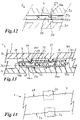
- the profile element 3 is configured as an elongated profile element 3 configured approximately in one plane, in which the profile element ends 31, 32 extend approximately in the same plane as the profile element body 30, as is shown in figure 11 is shown, a certain mobility of the profile element 3 can be provided transversely to its longitudinal extent.
- the provision of the two sealing elements 7, 8 can also ensure complete sealing against the penetration of liquid or other media into the interior 25 of the housing 2.
- the profile element 3 can be allowed to move approximately perpendicularly to its plane of extent, in order to be able to move or press the profile element 3 slightly in the direction of the heat-emitting electronic component 6 to reduce the thermal resistance, as is further the case will be explained below. It can thus play in this Direction may be provided to allow slight movement of the profile member while maintaining full sealing.
- connection connectors 4, 5 can, for example, be materially connected to the housing 2, which consists in particular of plastic, in particular an injection-molded plastic housing. In this way, penetration of liquid or moisture and other media from the outside into the interior 25 of the housing 2 in the area of the transition from the housing 2 to the connection connectors 4, 5 can be avoided in a particularly reliable manner. It is also possible to also connect the two housing parts 20, 21 of the housing 2 to one another in a materially bonded manner after the assembly of the arrangement 1 has been completed, for example by welding.
- first weld seam 100 being provided between the respective connection connectors 4 and 5 and the first housing part 20 and the second weld seam 101 for connecting the two housing parts 20, 21 between them.
- the assembly is carried out in the opposite position with respect to the later orientation of the arrangement, so that the second housing part 21 is at the bottom in the assembly direction and the first housing part 20, in which the electronic component 6 and any circuit board on which this is arranged, is provided are at the top in the mounting direction (see figure 2 ).
- the profile element ends 31, 32 in the slot-shaped openings 22 in the tab-shaped, protruding end sections 23 of the first housing part 20 a defined position or predetermined positioning of the profile element 3 in the housing 2 is possible.
- a defined positioning of the profile element 3 can also be provided for the heat-emitting electronic component or power electronics component, as is the case for example Figures 3 and 6 till 9 can be removed.
- the profile element 3 is mechanically fixed in the housing 2 . This is done, for example, by fixing elements 27 protruding inwards from the housing parts 20, 21, as shown in Figure 1 to 4 , 6 till 9 , 12 and 13 are shown, which attack on an outer side 34 of the profile element 3, abut or engage in what the Figures 12 and 13 can be better removed. Furthermore, the profile element 3 is laterally fixed in the housing by pre-assembly clamping elements 26 .
- the pre-clamping elements 26 are also den Figures 1 to 4 , 6 until 9 and 12 to 14.
- the pre-assembly clamping elements 26 are particularly good figure 2 and the figure 14 refer to.
- the pre-assembly clamping elements 26 are each arranged in pairs in the second housing part 21, ie the housing cover, and clamp on the outside along the longitudinal sides 38, 39 of the profile element 3 on this.
- the pre-assembly clamping elements 26 each include a support section 260, on which the profile element 3 rests, and a lateral clamping section 261, which laterally clamps along the longitudinal sides 38 and 39 of the profile element 3 to this.
- the clamping effect arises in each case in the interaction between two opposing lateral clamping sections 261 of two pre-assembly clamping elements 26, with the profile element 3 being interposed between the two, such as the figures 2 and 13 can be removed particularly well.
- the profile element 3 rests with its outside 33 on the support section 260 .
- the lateral clamping sections 261 of two opposite pre-assembly clamping elements 26 can press along the longitudinal sides 38, 39 of the profile element body 30 of the profile element 3 into the latter or into the outer wall provided there, in order to effect the clamping retention. this is in figure 14 implied.
- the lateral clamping sections 261 of two opposite pre-assembly clamping elements 26 engaging in a clamping and pressing manner on the profile element 3, the latter can be provided with notches or embossings along its two longitudinal sides 38, 39, for example approximately in the area of half the longitudinal extension, into which the lateral clamping portions 261 of the two opposing pre-assembly clamping elements 26 can engage.
- lateral impressions or indentations can be made wider than the lateral clamping sections 261 of the pre-assembly clamping elements 26 lying opposite one another, so that a slight displacement of the profile element in its longitudinal direction remains possible even when the lateral clamping sections 261 of the pre-assembly clamping elements 26 engage in the indentations or impressions of the profile element 3.
- Such a displacement in the longitudinal direction of the profile element 3 can take place, for example, in the event of thermal changes in length or due to manufacturing tolerances that can be compensated for in this way.
- the fixing elements 27 can, in particular the figures 1 , 3, 4 as well as 6 to 9 and 12, 13 can be seen, for example, pin-shaped or dome-shaped with a rounded contact surface.
- the rounded contact surface 270 is pressed into the outer wall 340 of the profile element 3, as particularly well figures 13 can be removed. This makes it possible to fix the profile element in the housing 2 very well, since the provision of the fixing elements 27 also allows tolerance compensation for manufacturing tolerances with regard to the profile element 3 on the one hand and the housing 2 on the other.
- the fixing elements 27 engage in the outer wall 340 of the profile element 3 in areas where in the A respective inner flow channel 37 is provided inside the profile element. On the one hand, this can prevent the webs 137 arranged between the inner flow channels from being damaged by the fixing elements 27 engaging in the outer wall 340 of the profile element 3 . On the other hand, it can also be prevented that the webs 137 inside the profile element 3 prevent tolerance compensation from being carried out.
- the profile element 3 in this embodiment has inner flow channels 37 of different widths, with the fixing elements engaging in the outer wall 340 of the profile element 3 in the region of the two widest inner flow channels 37 .
- the fixing elements 27 and the pre-assembly clamping elements 26 enable the profile element 3 to be fixed in position or position very well in the interior 25 of the housing 2 . It is also possible to provide a resilient mounting of the profile element 3 via the fixing elements and the pre-assembly clamping elements 26 , 27 .
- the fixing elements 27 and/or the pre-assembly clamping elements 26 can be designed as spring elements or rubber elements, for example. Due to manufacturing tolerances, it is possible that the distance between the profile element 3 and the heat-emitting electronic component 6 varies in part, especially in series production.
- the distance a between the surface of the heat-emitting electronic component 6 and the profile element 3 or its outer side 34 facing the component 6, as shown in figure 3 is shown may vary due to manufacturing tolerances.
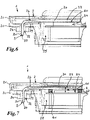
- the profile element 3 can, for example, have a mechanical Pressure can be applied to the heat source in the form of the heat-emitting electronic component 6, as in figure 6 implied.
- a means for exerting the pressure or movement pressure can be provided.
- the profile element 3 can be brought close to the heat source in the form of the heat-emitting electronic component 6.
- the combination of fixing elements 27 and pre-assembly clamping elements 26 can therefore be arranged in particular in the area of half the length of the housing or profile element and at its ends or in the area of the heat-emitting electronic component 6.
- the distance a between the Profile elements 3 and its outside 34 and the heat-emitting electronic component 6 are set and maintained accordingly.
- the depth of penetration of the fixing elements 27 in the outer wall 340 of the profile element 3 can be varied.
- the clear height h of the inner flow channel 37 can be reduced, for example, by a maximum of 50% by pressing in the outer wall 340 with the fixing elements 27 .
- a reduction in the range between 10 and 50% can be provided, for example a reduction by 40%, 30%, 20%, 10% or also by less than 10%.
- embossing or notching the profile element 3 in the area of its long sides 38, 39 does not lead to a significant reduction in the available flow cross section, in particular due to the fact that the adjacent to the long side walls 380, 390 are arranged Inner flow channels 37 at the profile element ends 31, 32 of the profile element 3 by in particular first sealing elements 7 (see figure 1 ) are often closed anyway.
- FIG. 7 An alternative way to reduce the thermal resistance to improve the heat transfer from the heat-emitting electronic component 6 to the heat-absorbing profile element 3 is in figure 7 shown.
- a defined distance between the profile element 3 and the heat-emitting electronic component 6 is created in that spacers 61, 62 are provided adjacent to the heat-emitting electronic component 6, against which the profile element 3 rests with its outer side 34, possibly exerting a mechanical pressure on the spacers 61, 62.
- the profile element 3 Since it is not the internal cavity of the housing 2 that is to be cooled, but the profile element 3, which is preferably made of aluminum and through which liquid flows, absorbs the heat given off by the heat-emitting electronic component 6 and from the housing interior 25 is to be transported away to the outside, the profile element 3 is arranged in a defined position relative to the heat-emitting electronic component 6 .
- the spacers 61, 62 By providing the spacers 61, 62, a desired, definable distance a between the profile element 3 and the heat-emitting electronic component 6 can also be created. This also provides a cost-effective way of compensating for manufacturing tolerances with regard to the profile element 3, but also for receiving and fixing by the fixing elements 27 and pre-assembly clamping elements 26 in the housing 2.
- a spring element can also be provided here, for example, which exerts the corresponding pressure on the profile element.
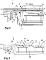
- figure 8 is a way to increase the surface of the profile element 3 by providing surface-enlarging elements, here by way of example indentations 35, 36 shown. Instead of notches 35, 36, grooves or other surface-enlarging elements and/or elements protruding into the interior of the profile element 3 can also be provided. These are in the area of the outside 33 of the profile element 3, thus on the opposite side of the heat-emitting electronic component 6, based on the profile element 3, arranged, however, with respect to the positioning in the longitudinal direction of the profile element 3 in the area Heat source, ie the heat-emitting electronic component 6, as well figure 8 can be removed particularly well.
- the notches 35, 36 not only can the heat-transferring surface be enlarged, but at the same time the flow in the at least one inner flow channel 37 of the profile element 3 can be more turbulent, so that the heat absorption in the cooling medium or coolant flowing through the Liquid heat exchanger flows in the form of the profile element 3, can be further improved.
- the profile element 3 can be bent in the area of its profile element body 30 or, as shown here, can be cranked. As a result, an optimal contact of the profile element 3 with its outer side 34 on the respective outer side 60 of the two heat-emitting electronic components 6a and 6b in the interior 25 of the housing 2 is possible. Since the profile element 3 is advantageously made of aluminum in the form of an aluminum extrusion profile, it can be easily bent, so that optimal adaptation to different overall heights of the heat-emitting electronic components 6 or 6a, 6b arranged in the interior 25 of the housing 2 is possible.
- the number of inner flow channels 37 and web areas of the profile element 3 arranged between them can be varied depending on its vertical stability.
- the design is such that a sufficient number or width of webs 137 or web areas is provided between the flow channels and compared to their diameter in order to withstand a pressure applied to the profile element 3 in the area where the profile element 3 is led out of the housing 2 to be able to There, the two sealing elements 7, 8 exert pressure on the profile element 3 in order to achieve the desired seal. Otherwise, if the number and/or width of the webs 137 or web regions between or adjacent to the flow channels 37 is insufficient, this could lead to an unwanted pressing in of the profile element 3 .
- the profile element 3 can be at least twice as wide as it is high.
- the width b of the profile element can be x times as large as its height H (see figure 2 ), where x can be an integer or rational number, e.g. 3, 4, 5, 6, 7 or another natural or rational number, such as 6.67. This also achieves sufficient stability of the profile element 3 in the direction in which it extends in height.
- lines for supplying and discharging cooling liquid or coolant can be connected to the two connection connectors 4, 5. It is thus possible to connect the arrangement 1 to a cooling system.
- a cooling system can be provided specifically for cooling the coolant flowing through the arrangement 1 or the profile element 3, which has the advantage that the inner flow channels 37 of the profile element can be protected against clogging with suspended matter, which leads to deposits .
- a connection is made, for example, to a cooling system of a vehicle, such as to an air conditioning system of this vehicle, it may be necessary to provide filter elements that remove suspended matter or Intercept particles from the cooling system before they get into the inner flow channels 37 of the profile element 3 and can clog or clog them.
- the profile element 3 is securely sealed in relation to the interior 25 of the housing 2 and thus the at least one heat-emitting electronic component 6 or 6a and 6b arranged therein, even when pressure is applied in the assembly direction (see arrow P1 in figure 2 ) of 1 mm, for example, is possible.
- the profile element 2 can still be reliably sealed against the interior 25 of the housing 2 and thus the at least one heat-emitting electronic component 6 or 6a arranged therein and 6b can also be ensured when pressure is applied in the direction of assembly. Penetration of moisture or liquid into the interior 25 of the housing 2 can thus be reliably prevented in both variants.
- the at least one heat-emitting electronic component in the housing is arranged, and the cooling system comprises at least one heat exchanger, numerous others can be formed, in particular any combinations of the features mentioned, wherein the heat exchanger is a liquid heat exchanger and comprises at least one profile element made of at least one thermally conductive material and wherein the at least a profile element is arranged in the housing in a predeterminable position relative to the at least one heat-emitting electronic component.
Landscapes
- Engineering & Computer Science (AREA)
- Microelectronics & Electronic Packaging (AREA)
- Physics & Mathematics (AREA)
- Thermal Sciences (AREA)
- Cooling Or The Like Of Electrical Apparatus (AREA)
Applications Claiming Priority (2)
| Application Number | Priority Date | Filing Date | Title |
|---|---|---|---|
| DE102020007137 | 2020-11-23 | ||
| DE102021005555 | 2021-11-09 |
Publications (1)
| Publication Number | Publication Date |
|---|---|
| EP4002970A1 true EP4002970A1 (fr) | 2022-05-25 |
Family
ID=81214558
Family Applications (1)
| Application Number | Title | Priority Date | Filing Date |
|---|---|---|---|
| EP21020589.4A Pending EP4002970A1 (fr) | 2020-11-23 | 2021-11-23 | Agencement pourvu de boîtier destiné à la réception d'un composant électronique exothermique et pourvu de système de refroidissement de celui-ci |
Country Status (2)
| Country | Link |
|---|---|
| EP (1) | EP4002970A1 (fr) |
| DE (1) | DE102021005798A1 (fr) |
Citations (6)
| Publication number | Priority date | Publication date | Assignee | Title |
|---|---|---|---|---|
| US5584183A (en) * | 1994-02-18 | 1996-12-17 | Solid State Cooling Systems | Thermoelectric heat exchanger |
| EP2031332A1 (fr) * | 2007-08-27 | 2009-03-04 | ABB Research LTD | Échangeur de chaleur |
| DE102010027998A1 (de) * | 2010-02-25 | 2011-12-15 | Edag Gmbh & Co. Kgaa | Aggregat mit Funktionseinheiten und Wärmetauschern |
| EP2645040A1 (fr) * | 2012-03-28 | 2013-10-02 | ABB Research Ltd. | Échangeur de chaleur pour convertisseurs de traction |
| EP3418653A2 (fr) | 2017-06-23 | 2018-12-26 | Voss Automotive GmbH | Dispositif de mise en température d'au moins un volume pouvant être mis en température, volume pouvant être mis en température doté d'au moins un tel dispositif ainsi que véhicule doté d'au moins un tel dispositif |
| DE102018002980A1 (de) | 2018-04-12 | 2019-10-17 | Voss Automotive Gmbh | Wärmetauscher-Einheit |
-
2021
- 2021-11-23 EP EP21020589.4A patent/EP4002970A1/fr active Pending
- 2021-11-23 DE DE102021005798.8A patent/DE102021005798A1/de active Pending
Patent Citations (6)
| Publication number | Priority date | Publication date | Assignee | Title |
|---|---|---|---|---|
| US5584183A (en) * | 1994-02-18 | 1996-12-17 | Solid State Cooling Systems | Thermoelectric heat exchanger |
| EP2031332A1 (fr) * | 2007-08-27 | 2009-03-04 | ABB Research LTD | Échangeur de chaleur |
| DE102010027998A1 (de) * | 2010-02-25 | 2011-12-15 | Edag Gmbh & Co. Kgaa | Aggregat mit Funktionseinheiten und Wärmetauschern |
| EP2645040A1 (fr) * | 2012-03-28 | 2013-10-02 | ABB Research Ltd. | Échangeur de chaleur pour convertisseurs de traction |
| EP3418653A2 (fr) | 2017-06-23 | 2018-12-26 | Voss Automotive GmbH | Dispositif de mise en température d'au moins un volume pouvant être mis en température, volume pouvant être mis en température doté d'au moins un tel dispositif ainsi que véhicule doté d'au moins un tel dispositif |
| DE102018002980A1 (de) | 2018-04-12 | 2019-10-17 | Voss Automotive Gmbh | Wärmetauscher-Einheit |
Also Published As
| Publication number | Publication date |
|---|---|
| DE102021005798A1 (de) | 2022-05-25 |
Similar Documents
| Publication | Publication Date | Title |
|---|---|---|
| DE102013015179B4 (de) | Wärmetauscheranordnung und Herstellungsverfahren | |
| EP2458633B1 (fr) | Système semi-conducteur de puissance | |
| EP1931176B1 (fr) | Dispositif de chauffage électrique et son procédé de fabrication | |
| EP2797382B1 (fr) | Chauffe-eau et système de chauffage pour un véhicule électrique avec chauffe-eau | |
| DE112016000129B4 (de) | Wärmetauscher zum Kühlen eines elektrischen Elements, sowie Wärmetauscheranordnung und Kühlmodul | |
| EP3647704B1 (fr) | Dispositif de transfert de chaleur destiné à la mise en température des batteries et des composants de l'électronique de puissance | |
| DE102015221265A1 (de) | Fluiddurchströmbarer Kühlkörper für elektrische Energiespeicher | |
| DE112011101941B4 (de) | Verfahren zum Aufbauen eines Wärmetauschers sowie Wärmetauschervorrichtung | |
| DE102015202142A1 (de) | Elektrische Einrichtung | |
| DE102010038781A1 (de) | Kombi-Wärmetauscher und Verfahren zur Herstellung eines Kombi-Wärmetauschers | |
| DE19848169A1 (de) | Vorrichtung zum Beheizen von Innenräumen, insbesondere von Kraftfahrzeugen | |
| DE102007003821A1 (de) | Transistorklemmvorrichtung | |
| DE102006055216B4 (de) | Heizeinrichtung für Dieselkraftstoff und beheizbares Dieselfiltersystem | |
| EP3271979B1 (fr) | Système modulaire | |
| DE102016222630A1 (de) | Kühlvorrichtung und Verfahren zum Herstellen einer Kühlvorrichtung | |
| EP1289011A2 (fr) | Appareil de commutation ou de contrôle | |
| EP3553450B1 (fr) | Unité d'échangeur de chaleur | |
| DE102022116921A1 (de) | Bauteil einer elektrischen Heizvorrichtung und elektrische Heizvorrichtung | |
| DE102009033988B4 (de) | Heizvorrichtung | |
| EP4002970A1 (fr) | Agencement pourvu de boîtier destiné à la réception d'un composant électronique exothermique et pourvu de système de refroidissement de celui-ci | |
| DE102020209923B3 (de) | Schaltungsträgeranordnung und Verfahren zum Herstellen einer solchen Schaltungsträgeranordnung | |
| DE102021213315A1 (de) | Kühlvorrichtung | |
| DE102018208232A1 (de) | Bauteil mit einer durch ein Einlegeelement optimierten Kühlleistung und Kraftfahrzeug mit zumindest einem Bauteil | |
| EP4720580A1 (fr) | Dispositif chauffant | |
| DE102023209171A1 (de) | Batterieeinheit |
Legal Events
| Date | Code | Title | Description |
|---|---|---|---|
| PUAI | Public reference made under article 153(3) epc to a published international application that has entered the european phase |
Free format text: ORIGINAL CODE: 0009012 |
|
| STAA | Information on the status of an ep patent application or granted ep patent |
Free format text: STATUS: THE APPLICATION HAS BEEN PUBLISHED |
|
| AK | Designated contracting states |
Kind code of ref document: A1 Designated state(s): AL AT BE BG CH CY CZ DE DK EE ES FI FR GB GR HR HU IE IS IT LI LT LU LV MC MK MT NL NO PL PT RO RS SE SI SK SM TR |
|
| STAA | Information on the status of an ep patent application or granted ep patent |
Free format text: STATUS: REQUEST FOR EXAMINATION WAS MADE |
|
| 17P | Request for examination filed |
Effective date: 20220802 |
|
| RBV | Designated contracting states (corrected) |
Designated state(s): AL AT BE BG CH CY CZ DE DK EE ES FI FR GB GR HR HU IE IS IT LI LT LU LV MC MK MT NL NO PL PT RO RS SE SI SK SM TR |
|
| STAA | Information on the status of an ep patent application or granted ep patent |
Free format text: STATUS: EXAMINATION IS IN PROGRESS |
|
| 17Q | First examination report despatched |
Effective date: 20240318 |