EP4003025B1 - Dispositif pour l'application de matériau d'épandage - Google Patents
Dispositif pour l'application de matériau d'épandage Download PDFInfo
- Publication number
- EP4003025B1 EP4003025B1 EP20750566.0A EP20750566A EP4003025B1 EP 4003025 B1 EP4003025 B1 EP 4003025B1 EP 20750566 A EP20750566 A EP 20750566A EP 4003025 B1 EP4003025 B1 EP 4003025B1
- Authority
- EP
- European Patent Office
- Prior art keywords
- belt
- dough
- sprinkable
- bulk
- receiving
- Prior art date
- Legal status (The legal status is an assumption and is not a legal conclusion. Google has not performed a legal analysis and makes no representation as to the accuracy of the status listed.)
- Active
Links
Images


Classifications
-
- A—HUMAN NECESSITIES
- A21—BAKING; EDIBLE DOUGHS
- A21C—MACHINES OR EQUIPMENT FOR MAKING OR PROCESSING DOUGHS; HANDLING BAKED ARTICLES MADE FROM DOUGH
- A21C9/00—Other apparatus for handling dough or dough pieces
- A21C9/04—Apparatus for spreading granular material on, or sweeping or coating the surfaces of, pieces or sheets of dough
-
- A—HUMAN NECESSITIES
- A21—BAKING; EDIBLE DOUGHS
- A21C—MACHINES OR EQUIPMENT FOR MAKING OR PROCESSING DOUGHS; HANDLING BAKED ARTICLES MADE FROM DOUGH
- A21C3/00—Machines or apparatus for shaping batches of dough before subdivision
- A21C3/08—Machines for twisting strips of dough, e.g. for making pretzels
Definitions
- the invention relates to a device for applying bulk or sprinkling material to baked goods or dough pieces according to the preamble of patent claim 1 and to a dough plant or a plant for baked goods comprising such a device.
- Devices for sprinkling baked goods or dough pieces are known from the state of the art. These devices usually require a lot of cleaning and take up a lot of space.
- the bulk or sprinkling material is usually applied to the baked goods or dough pieces from above.
- the sprinkling of the bulk or sprinkling material causes the bulk or sprinkling material to jump, which requires a lot of cleaning and results in the loss of bulk or sprinkling material. It is also necessary to moisten the dough pieces or baked goods beforehand to allow the sprinkling material to adhere to the baked goods or dough pieces.
- US1711716 A discloses a device for applying bulk or spreading material according to the prior art.
- the object of the invention is therefore to provide a device for sprinkling baked goods or dough pieces which requires little space, minimises the cleaning effort and enables a uniform or targeted distribution of the bulk or sprinkling material on the baked goods or dough pieces.
- the device according to the invention enables a particularly compact construction, cleaning is made considerably easier and, in addition, a targeted application of bulk material to baked goods/dough pieces is made possible.
- the arrangement according to the invention makes it possible for automated operation to not require a return unit for returning the bulk or spreading material.
- a return unit with vacuum, blower, screw conveyor unit and/or or conveyor belts. Cleaning such return units is difficult because cleaning hoses, valves, pumps, screw conveyors, belt conveyors, blowers, etc. is often not possible and causes enormous costs.
- the bulk or grit return unit By eliminating the bulk or grit return unit, the high energy consumption and cleaning effort required for conventional returns are completely eliminated. If the bulk or grit unit is therefore arranged in such a way that the bulk and grit that trickles off the conveyor belt goes directly into the bulk or grit conveyor following gravity, a compact, easy-to-clean, energy- and cost-efficient device can be provided.
- the arrangement according to the invention also enables significant space savings.
- the conveyor belt and the covering belt are partially arranged one above the other, so that space can be saved.
- the conveyor belt and the covering belt are arranged in such a way that the bulk spreading material can be transported upwards against the direction of gravity. Because the spreading material is clamped between the conveyor belt and the covering belt in the transfer area, the spreading pattern is maintained and targeted and even spreading can be achieved, with the spreading material being transported further on the covering belt after the transfer area.
- the distance between the covering belt and the conveyor belt is greater before and after the transfer area than in the transfer area.
- the distance between the covering belt and the conveyor belt is adjustable in the transfer area, so that the distance can be adapted to the grain size of the spreading material currently being used, whereby the bulk spreading material can be clamped particularly gently.
- the covering belt can have a gradient of a maximum of 60°, in particular from 0° to 30°, preferably from 0° to 10°, at the upper end point of the transfer area. This prevents the bulk or spreading material from slipping on the covering belt.
- the gradient is specified as the angle that the covering belt forms with the horizontal in the area following the transfer area in the direction of travel of the covering belt.
- the receipt belt and the conveyor belt are each guided in a common curve in the transfer area.
- the radius of the curve described by the receipt belt is smaller than or equal to the radius of the curve described by the conveyor belt.
- a particularly even distribution of the bulk or spreading material can be achieved if the covering belt and the conveyor belt are each guided in a circular arc in the transfer area. It can be provided that the circular arcs described by the covering belt and conveyor belt have the same center point and a common center angle of at least 90°, preferably at least 170°. In this way, the bulk or spreading material can be clamped particularly easily and the bulk or spreading material can be transferred from the conveyor belt to the covering belt in a particularly targeted manner.
- the distance between the receipt belt and the conveyor belt corresponds to the width of the circular ring.
- the covering belt is arranged in sections, in particular at least in the transfer area, around a drum, with the circumference of the drum defining the circular arc described by the covering belt.
- the drum can have a diameter that allows a large part of the height difference between the section of the conveyor belt arranged under the spreading material unit and the dough take-over to be overcome in the transfer area.
- the wrap angle of the covering belt around the drum is at least 180°. This enables a compact design that allows the covering belt to be guided over just two deflections, so that cleaning is made easier.
- the wrap angle can be at least 200°.
- the deflections around which the covering belt is guided have a different diameter, so that on the one hand the transfer area is as large as possible to enable precise transfer of the bulk or spreading material, and on the other hand the space required by the covering belt is as small as possible to enable a compact design. For example, this can enable at least partial Arrangement of the bulk or spreading material unit below the dough discharge can be achieved, which supports a particularly compact design of the device.
- a particularly compact design of the device is possible if the diameter of the drum corresponds at least to the height of the spreading material unit. Since the spreading material unit has a certain height due to its function, it is necessary to transport the bulk or spreading material from the height of the application to the conveyor belt to the height of the dough takeover, whereby this can be made possible in the transfer area by the drum.
- a particularly stable and compact design of the device can be achieved if the drum is designed as a drive drum of the receipt belt.
- the conveyor belt in the transfer area is guided over deflection rollers, with the deflection rollers running in the opposite direction to the covering belt, in particular to the drum of the covering belt.
- the deflection rollers are arranged in such a way that the conveyor belt is guided in an arc, in particular in a circular arc.
- the conveyor belt can be guided over a deflection roller designed as a knife edge at the end of the transfer area in the running direction of the conveyor belt.
- the knife edge makes it possible to enable the dough pieces to be transferred with a minimal transfer angle.
- the transfer angle can be further reduced if the loading belt has a slight incline.
- cleaning of the conveyor belt can be made easier if the conveyor belt has a knife edge at the end of the transfer area in the running direction of the conveyor belt or comprises an arranged deflection roller, wherein the knife edge or the deflection roller is mounted on a pivotable Bearings are arranged in such a way that the conveyor belt can be relaxed by pivoting the deflection roller.
- the topping belt is guided over a topping belt deflection roller at the dough discharge.
- This arrangement allows excess bulk or spreading material to be returned to the spreading material unit without additional energy expenditure by utilizing gravity.
- a spreading material scraper is provided in the running direction of the topping belt after the topping belt deflection roller, so that excess bulk or spreading material can be introduced from the topping belt into the spreading material unit.
- the energy consumption can also be kept low by providing that the bulk or spreading material unit comprises a bulk or spreading material container for receiving the bulk or spreading material to be applied and a spreading device arranged in the direction of gravity below the bulk or spreading material container for applying the bulk or spreading material. This also allows the structure to be made very compact.
- a further transport unit is provided which is arranged in such a way that at the dough delivery, pieces of dough can be delivered from the covering belt to the further transport unit, wherein it is provided in particular that an intermediate space is provided between the covering belt and the further transport unit, which is designed in such a way that bulk or spreading material located on the covering belt can be transported through the intermediate space between the covering belt and the further transport unit.
- the device in particular as a further transport unit, has a drip unit for freeing the dough pieces from poorly adhering spreading material, wherein the dough pieces can be delivered from the topping belt to the drip unit at the dough delivery point, wherein the drip unit is designed in such a way that poorly adhering spreading material can be removed, and wherein it is particularly provided that removed bulk or spreading material can be introduced into the spreading material unit.
- a mesh belt can be provided as the drip unit. This allows excess bulk or spreading material to be effectively removed.
- a pressure roller is arranged above the topping belt between the dough take-over and dough delivery points so that dough pieces on the topping belt can be pressed onto the bulk or spreading material by the pressure roller, whereby it is particularly provided that the distance between the pressure roller and the topping belt is adjustable.
- the bulk or spreading material can thus be pressed deeper into the dough pieces and thus better held onto the dough pieces. In this way, a particularly even and rich spreading can be achieved. Furthermore, it is sometimes possible to dispense with pre-moistening the dough pieces, which makes cleaning the device easier.
- the transport units can be provided with a floating bearing on one side.
- This type of bearing can be provided either for the loading belt, the conveyor belt or the drip unit, or for several or all of these components. It can preferably be provided that all bearings are arranged on the same side of the device, in particular in the running direction of the loading belt next to the device, in order to make cleaning particularly easy.
- the bearing can also be designed on a removable mandrel. This achieves particularly stable bearings that still enable easy cleaning.
- the conveyor belt can be arranged on a frame, the frame being mounted in such a way that it can be removed from the device, in particular transversely to the running direction of the covering belt. Cleaning the other components can also be made easier in this way.
- the frame can be provided with swivel wheels. This makes it possible to move the frame perpendicular to the running direction of the conveyor belt.
- the invention also relates to a dough plant with at least one device as described above.
- the compact design of the device means that the space required for a dough plant can be significantly reduced.
- the dough system includes a sprinkling device for sprinkling from above, which is arranged in such a way that dough pieces can be sprinkled on both sides without turning them. Turning the dough pieces is particularly difficult with delicate dough pieces, since the shape of the dough pieces during These difficulties can be overcome by an arrangement according to the invention
- the dough system comprises two previously described devices for sprinkling dough pieces on both sides, wherein the devices are arranged in such a way that the dough pieces are turned between the devices. This enables a particularly compact system construction.
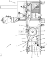
- a combination of a device 1 according to the invention and a sprinkling device 23 for sprinkling from above is shown.
- the device 1 according to the invention comprises a covering belt 2, a conveyor belt 3 and a sprinkling unit 4.
- the covering belt 2 and the conveyor belt 3 are belt conveyors or conveyor belts which are welded together endlessly in the embodiment shown. They can advantageously be designed as an elastic rubber belt or as a fabric belt with a smooth or structured surface or with an elastic or soft coating.
- the receipt belt 2 is guided around a drum 10 and around a receipt belt deflection roller 13.
- the upper run of the receipt belt 2 runs from the drum 10 to the receipt belt deflection roller 13 and defines the transport plane.
- the lower run of the receipt belt 2 runs from the receipt belt deflection roller 13 to the drum 10 and defines the return plane.
- a transfer area 5 is provided between the return plane and the transport plane, in which the conveyor belt 3 is arranged on the outside with respect to the return of the receipt belt 2.
- a section of the conveyor belt 3 is arranged adjacent to the covering belt 2, following the course of the drum 10, with the distance between the conveyor belt 3 and the covering belt 2 being uniform. Before and after the transfer area 5, the distance between the conveyor belt 3 and the covering belt 2 is greater than in the transfer area 5.
- the covering belt 2 and the conveyor belt 3 are guided in a common arc, with the covering belt 2 and the conveyor belt 3 each being arranged in a circular arc to the same center, and with the distance between the covering belt 2 and the conveyor belt 3 corresponding to the width of the associated circular ring.
- Spreading material is transported on the conveyor belt 3 to the transfer area 5 and clamped between the conveyor belt 3 and the covering belt 2 in the transfer area 5 and transported upwards.
- the spreading material is transferred from the conveyor belt 3 to the covering belt 2.
- the covering belt 2 has a gradient of 5°.
- the The transport level, or the upper run of the conveyor belt 2 generally has a gradient of 5°.
- the dough pieces to be sprinkled are transferred to the covering belt 2.
- the dough pieces are transported by the covering belt 2 in the transport plane from the dough take-over 6 to a dough delivery 7.
- the covering belt 2 runs over the covering belt deflection roller 13. There, the dough pieces are delivered from the covering belt 2.
- the spreading material unit 4 is suitable for receiving and applying the bulk or spreading material.
- the conveyor belt 3 runs under the spreading material unit 4 in a section that is arranged in front of the transfer area 5 in the running direction of the conveyor belt 3. In this section, spreading material is applied from the spreading material unit 4 to the conveyor belt 3.
- the spreading material unit 4 is mounted on a base unit of the device 1.
- the spreading unit 4 has a spreading material container 8 and a spreading device 9 arranged below the spreading material container 8.
- the spreading material container 8 is suitable for receiving the bulk or spreading material to be applied.
- the spreading material container 8 can be pulled out of the spreading unit 4.
- a screw conveyor can be provided, for example, which conveys spreading material from a storage container into the spreading material container 8.
- the spreading device 9 is used to apply the bulk or spreading material from the spreading material container 8 to the conveyor belt 3.
- the bulk or spreading material is applied by the spreading device 9 to the receiving area of the conveyor belt 3 or is spread from above from the spreading device 9 onto the conveyor belt 3.
- a minimum fall height of the bulk or spreading material can be achieved, which largely prevents the bulk or spreading material from jumping when it is applied to the conveyor belt 3.
- the spreading material is transferred from the conveyor belt 3 to the covering belt 2 in the transfer area 5 and transported from the covering belt 2 to the dough discharge 7.
- the spreading material container 8 is arranged below the covering belt deflection roller 13. Bulk or Gritting material that falls off the grit belt 2 at the grit belt deflection roller 13 passes into the grit container 8 by gravity and can be collected in the grit container 8 and can thus be reused.
- the dough pieces are taken over at the dough takeover 6, whereby dough pieces are preferably taken over onto the topping belt 2 without sprinkling on the underside.
- a transfer nose is arranged between the upstream sprinkling device 23 for sprinkling from above and the device 1. This enables dough pieces to be transferred gently and without turning.
- the transfer nose can be arranged above the drum 10. This arrangement enables a compact design of the device 1, while at the same time enabling gentle treatment of the dough pieces.
- the dough pieces come to rest on the bulk or spreading material that is already on the covering belt 2.
- the spreading material is pressed into the dough pieces by the weight of the dough pieces and sticks to them.
- the dough pieces may or may not be moistened beforehand.
- a pressure roller (not shown) can be arranged above the covering belt 2. This pressure roller can press the bulk or spreading material deeper into the dough pieces, making it stick even better.
- the dough pieces sprinkled on the underside are transferred to a further transport unit 14 at the dough discharge 7.
- the further transport unit 14 is designed as a drip unit or as a grid belt. Bulk or grit material that does not stick to the dough pieces and is therefore surplus is not transferred to the further transport unit 14 at the dough discharge 7, but falls off the covering belt 2. The bulk or grit material then goes directly into the grit container 8, which is arranged under the dough discharge 7.
- a grit scraper 15 is provided, which is arranged in the running direction of the belt 2 after the belt deflection roller 13.
- the grit scraper 15 is constructed in several parts in order to be at least partially removable and to enable easy cleaning. Alternatively, for example, a one-piece removable grit scraper 15 can also be provided. The grit scraper 15 removes bulk or grit from the conveyor belt 2 and falls into the grit container 8.
- the trickle-down unit is arranged on the base unit of the device 1.
- the trickle-down unit has an input nose that can be adjusted in the longitudinal direction. This enables adaptation to the belt tension of the covering belt 2 and the trickle-down unit is arranged with an adjustable gap to the covering belt deflection roller 13. This arrangement allows bulk or spreading material to fall through the gap between the covering belt 2 and the trickle-down unit and the carryover of bulk or spreading material can be avoided.
- the belt body of the trickle-down unit is removable or can be pulled out of the device 1.
- the drive is via a detachable coupling.
- a motor with or without a detachable cable connection can be provided as the drive for the drip unit.
- the device 1 according to the invention requires significantly less space than the known sprinkling device 23 for sprinkling from above.
- the more compact design also makes cleaning the device 1 much easier.
- the movable components of the device 1 are locked to the base unit of the device 1.
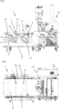
- Fig.2 shows that the conveyor belt 3 is mounted on a frame 16.
- the frame 16 can be moved by swivel wheels 17, whereby the frame 16 can be removed from the device 1, whereby a displacement perpendicular to the running direction of the conveyor belt 3 out of the device 1 is possible. This makes cleaning the device 1 easier.
- the swivel wheels 17 can be designed with or without brakes.
- the device 1 is constructed in such a way that the covering belt 2, the drip unit and the conveyor belt 3 are mounted on one side in a floating manner.
- the bearings 20 are all arranged on the right in the running direction of the covering belt 2 from the dough take-over 6 to the dough discharge 7. Due to the one-sided mounting cleaning is made easier.
- storage on a removable mandrel is provided.
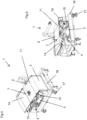
- Fig. 4 to 7 the device 1 is shown in isolation. It can be seen that the conveyor belt 3 has a deflection roller 12 designed as a knife edge 11 at the end of the transfer area 5.
- the knife edge 11 enables a flat arrangement of the transfer nose and is therefore advantageous for a gentle transfer of the dough pieces.
- the covering belt 2 and the suspension of the covering belt 2 are shown as a single component.
- the covering belt 2 is attached to the base unit of the device 1.
- the base unit can be connected to preceding and subsequent system components via adjustable connections. For example, a connection with threaded spindles can be provided.
- the covering belt 2 is mounted on one side in a floating manner.
- the covering belt 2 is guided in a circular arc around the drum 10 in the transfer area 5.
- the drum 10 is mounted on a mandrel of the belt body, so that cleaning is particularly easy due to the detachable connection and sufficient stability can be achieved even with larger nominal widths. By loosening the fixing screw 19, it is possible to pull the drum 10 off the mandrel.
- the drum 10 has a diameter of 430 mm.
- the drum 10 is the drive drum of the covering belt 2.
- the wrap angle of the covering belt 2 around the drum 10 is greater than 180°.
- the covering belt 2 is also guided over the covering belt deflection roller 13.
- An angle-symmetrical tension of the covering belt 2 is particularly advantageous in order to reduce the load on the bearing of the covering belt deflection roller 13.
- the transport plane and the return plane enclose an angle of 45° in the embodiment shown.
- the covering belt 2 has a running direction in which the upper run of the covering belt 2 is moved from the drum 10 to the covering belt deflection roller 13.
- the topping belt 2 runs in the transport plane at an angle of 5° to the horizontal, which enables a particularly gentle transfer of the dough pieces from the transfer nose to the topping belt 2. It can be provided that the angle of the topping belt 2 or its inclination to the horizontal is adjustable and, for example, the topping belt 2 runs horizontally in this area.
- the receipt belt deflection roller 13 is guided by means of sliding parts in the side plate and is adjustable by means of a toggle lever 18.
- the receipt belt 2 can be relaxed and thus pulled off the drum 10 and the receipt belt deflection 13 in order to achieve easier cleaning of the components, including the conveyor belt and the receipt belt.
- the conveyor belt 3 is arranged on the movable frame 16.
- the conveyor belt 3 is not mounted on a movable frame, and the other components of the device 1 can be raised or lowered for cleaning.
- the conveyor belt 3 is guided over deflection rollers 12. It can be advantageous if a belt support supports the conveyor belt 3 up to the beginning of the transfer area 5. In the transfer area 5, the conveyor belt 3 is guided over three deflection rollers 12, which enable an arrangement in a circular arc.
- the circular arc follows the course of the drum 10.
- the conveyor belt 3 is arranged so that the circular arc has a central angle of 175°.
- the loading belt 2 and the conveyor belt 3 are arranged in the device 1 so that in the transfer area 5 the distance between the loading belt 2 and the conveyor belt 3 is adjustable and essentially corresponds to the grain size of the bulk or scattered material.
- the scattered material can be, for example, poppy seeds, sesame seeds, oat flakes or other bulk or scattered material commonly used in bakeries.
- the drum 10 of the covering belt 2 and the deflection rollers 12 of the conveyor belt 3 have an opposite running direction, the covering belt 2 runs clockwise in the embodiment shown and the conveyor belt 3 runs anti-clockwise. In the transfer area 5, the bulk or spreading material is thus gently transported upwards.
- the uppermost deflection roller 12 of the conveyor belt 3 is arranged, which is designed as a knife edge 11.
- a scraper can optionally be provided at this point to prevent the bulk or scattered material from being dragged along the conveyor belt 3 beyond the transfer area 5.
- the knife edge 11 makes the end of the transfer area 5 flat, so that the transfer nose from the previous system component can be arranged at a flat angle to the topping belt 2 in order to enable a gentle transfer of the dough pieces.
- the Fig. 16 to 19 show the conveyor belt 3 without the frame 16.
- the conveyor belt 3 is guided over a total of five deflection rollers and driven by a drive drum.
- This drive drum can be designed as a drum motor, with a plug-on motor or with a mechanical drive by means of a belt, chain or coupling.
- the drive drum is shown as a drum motor and simultaneously functions as a tensioning shaft.
- the conveyor belt 3 is tensioned or relaxed using a toggle lever 18. Alternatively, other known tensioning elements can be provided.
- the drive drum is mounted in the side plate using sliding parts.
- the belt body is cantilevered on one side so that after the tensioning and drive shaft have been relaxed, the conveyor belt 3 can be easily pulled off the belt body.
- the Fig. 20 to 23 show the conveyor belt 3 in a relaxed state.
- the knife edge 11 is pivoted upwards about a pivot point. This pivoting of the knife edge 11 causes the conveyor belt 3 to relax. This makes it easier to remove, change the belt and clean the device 1.
- the device 1 according to the invention therefore enables precise sprinkling of dough pieces with a compact system component that is particularly easy to clean.
Landscapes
- Life Sciences & Earth Sciences (AREA)
- Engineering & Computer Science (AREA)
- Food Science & Technology (AREA)
- Manufacturing And Processing Devices For Dough (AREA)
- Structure Of Belt Conveyors (AREA)
Claims (15)
- Dispositif d'application de produit en vrac ou à disperser, en particulier d'application de produit en vrac ou à disperser important pour des pâtisseries, de préférence du pavot ou du sésame, sur le côté inférieur de morceaux de pâte comprenant- une bande de répartition (2) pour le transport des morceaux de pâte d'un système de prise en charge de pâte (6) à un système de distribution de pâte (7), dans lequel des morceaux de pâte non dispersés au niveau du système de prise en charge de pâte (6) sur son côté inférieur peuvent être pris en charge sur la bande de répartition (2) et des morceaux de pâte dispersés au niveau du système de distribution de pâte (7) sur son côté inférieur peuvent être distribués par la bande de répartition (2), dans lequel les morceaux de pâte peuvent être transportés dans un plan de transport de la bande de répartition (2) du système de prise en charge de pâte (6) au système de distribution de pâte (7) et dans lequel la bande de répartition (2) est guidée dans un plan de retour en dessous du plan de transport de la bande de répartition (2) de nouveau au système de prise en charge de pâte (6),- une unité de produit à disperser (4) pour la réception et l'application du produit en vrac ou à disperser,- une bande de transport (3), dans lequel la bande de transport (3) est agencée par sections sous l'unité de produit à disperser (4) et dans lequel du produit en vrac ou à disperser peut être appliqué sur la bande de transport (3) par l'unité de produit à disperser (4),dans lequel l'unité de produit à disperser (4) est agencée en dessous du plan de transport de telle manière que du produit en vrac ou à disperser excédentaire ruisselle à l'extrémité du plan de transport de la bande de répartition (2) dans l'unité de produit à disperser (4), et dans lequel la bande de répartition (2) et la bande de transport (3) sont agencées entre le plan de retour et le plan de transport de la bande de répartition (2) dans une zone de transmission (5) à une distance en particulier réglable l'une par rapport à l'autre ou reposant l'une contre l'autre de telle manière que du produit en vrac ou à disperser puisse être serré entre la bande de répartition (2) et la bande de transport (3) et puisse être transmis dans la zone de transmission (5) de la bande de transport (3) à la bande de répartition (2), dans lequel la bande de transport (3) est agencée dans la zone de transmission (5) suivant l'étendue de la bande de répartition (2), en particulier à l'extérieur par rapport au retour de la bande de répartition (3).
- Dispositif selon la revendication 1, caractérisé en ce que la bande de répartition (2) présente au point d'extrémité supérieur de la zone de transmission (5) une pente de 60° maximum, en particulier de 0° à 30°, de préférence de 0° à 10°.
- Dispositif selon la revendication 1 ou 2, caractérisé en ce que la bande de répartition (2) et la bande de transport (3) sont guidées respectivement dans un arc commun dans la zone de transmission (5).
- Dispositif selon la revendication 3, caractérisé en ce que dans la zone de transmission (5), la bande de répartition (2) et la bande de transport (3) sont guidées respectivement dans un arc de cercle, dans lequel il est en particulier prévu que les arcs de cercle décrits par la bande de répartition (2) et la bande de transport (3) présentent le même point médian et un angle de point médian commun d'au moins 90°, de préférence d'au moins 170°.
- Dispositif selon l'une quelconque des revendications 1 à 4, caractérisé en ce que la bande de répartition (2) est agencée s'étendant par sections, en particulier dans la zone de transmission (5), autour d'un tambour (10), dans lequel la périphérie du tambour (10) prédéfinit un arc de cercle décrit par la bande de répartition (2), et dans lequel il est en particulier prévu que l'angle d'enroulement de la bande de répartition (2) autour du tambour (10) s'élève à au moins 180°, en particulier à au moins 200° et/ou dans lequel il est en particulier prévu que le tambour (10) soit réalisé comme tambour d'entraînement de la bande de répartition (2).
- Dispositif selon la revendication 5, caractérisé en ce que le diamètre du tambour (10) correspond au moins à la hauteur de l'unité de produit à disperser (4).
- Dispositif selon l'une quelconque des revendications 1 à 6, caractérisé en ce que la bande de transport (3) présente dans le sens de la marche de la bande de transport (3) à l'extrémité de la zone de transmission (5) une arête de couteau (11) ou comprend un rouleau de déviation agencé, dans lequel l'arête de couteau (11) ou le rouleau de déviation est agencé sur un logement pivotant de telle manière que la bande de transport (3) puisse être desserrée par pivotement du rouleau de déviation.
- Dispositif selon l'une quelconque des revendications 1 à 7, caractérisé en ce que la bande de répartition (2) est guidée au niveau du système de distribution de pâte (7) par le biais d'un rouleau de déviation de bande de répartition (13) et une racle de produit à disperser (15) est prévue de préférence dans le sens de la marche de la bande de répartition (2) après le rouleau de déviation de bande de répartition (13) de sorte que du produit en vrac ou à disperser excédentaire puisse être introduit de la bande de répartition (2) dans l'unité de produit à disperser (4).
- Dispositif selon l'une quelconque des revendications 1 à 8, caractérisé en ce que l'unité de produit à disperser (4) comprend un récipient de produit à disperser (8) pour la réception du produit en vrac ou à disperser à appliquer et comprend un dispositif de dispersion (9) agencé dans le sens de la force de gravité sous le récipient de produit à disperser (8) pour l'application du produit à disperser.
- Dispositif selon l'une quelconque des revendications 1 à 9, caractérisé en ce qu'une autre unité de transport (14) est prévue, laquelle est agencée de telle manière qu'au niveau du système de distribution de pâte (7), des morceaux de pâte puissent être distribués de la bande de bande de répartition (2) à l'autre unité de transport (14), dans lequel il est en particulier prévu qu'un espace intermédiaire soit prévu entre la bande de répartition (2) et l'autre unité de transport, espace qui est réalisé de telle manière que du produit en vrac ou à disperser se trouvant sur la bande de répartition (2) puisse être transporté, en particulier ruisselé, par l'espace intermédiaire entre la bande de répartition (2) et l'autre unité de transport (14).
- Dispositif selon l'une quelconque des revendications 1 à 10, caractérisé en ce que le dispositif présente, en particulier comme autre unité de transport (14), une unité de ruissellement, en particulier une bande à grille, pour la libération de morceaux de pâte de produit en vrac ou à disperser à mauvaise adhérence, dans lequel au niveau de système de distribution de pâte (7), les morceaux de pâte peuvent être distribués de bande de répartition (2) à l'unité de ruissellement, dans lequel l'unité de ruissellement est réalisée de telle manière que du produit en vrac ou à disperser à mauvaise adhérence puisse être retiré, et dans lequel il est en particulier prévu que du produit à disperser retiré puisse être introduit dans l'unité de produit à disperser (4).
- Dispositif selon l'une quelconque des revendications 1 à 11, caractérisé en ce qu'un rouleau de pressage est agencé entre le système de prise en charge de pâte (6) et le système de distribution de pâte (7) au-dessus de la bande de répartition (2) de sorte que des morceaux de pâte se trouvant sur la bande de répartition (2) puissent être pressés sur le produit en vrac ou à disperser par le rouleau de pressage, dans lequel il est de préférence prévu que la distance soit réglable entre le rouleau de pressage et la bande de répartition (2).
- Dispositif selon l'une quelconque des revendications 1 à 12, caractérisé en ce que la bande de répartition (2) et/ou la bande de transport (3) et/ou l'unité de ruissellement (14) sont logés en porte-à-faux d'un côté, en particulier dans le sens de la marche de la bande de répartition (2) à côté du dispositif, dans lequel il est en particulier prévu que tous les paliers soient agencés sur le même côté du dispositif (1), et dans lequel le logement est de préférence réalisé sur une épine amovible.
- Dispositif selon l'une quelconque des revendications 1 à 13, caractérisé en ce que la bande de transport (3) est agencée sur un cadre (16), dans lequel le cadre (16) est logé en particulier sur des roues de pivotement (17) de sorte qu'il puisse être retiré du dispositif, dans lequel il peut être déplacé de préférence normalement au sens de la marche de la bande de transport (3).
- Installation de pâte avec au moins un dispositif (1) selon l'une quelconque des revendications 1 à 14, dans laquelle il est en particulier prévu que l'installation de pâte comprenne un dispositif de dispersion (23) pour la dispersion de dessus, qui est agencé de telle manière que des morceaux de pâte puissent être dispersés sans inversion des deux côtés,
et/ou dans laquelle il est en particulier prévu que l'installation de pâte comprenne deux dispositifs (1) selon l'une quelconque des revendications 1 à 14, dans laquelle les dispositifs (1) sont agencés de telle manière qu'une inversion des morceaux de pâte soit prévue entre les dispositifs (1).
Applications Claiming Priority (2)
| Application Number | Priority Date | Filing Date | Title |
|---|---|---|---|
| ATA50681/2019A AT522837B1 (de) | 2019-07-26 | 2019-07-26 | Vorrichtung zum Aufbringen von Streugut |
| PCT/AT2020/060276 WO2021016643A1 (fr) | 2019-07-26 | 2020-07-24 | Dispositif pour appliquer des produits à disperser |
Publications (3)
| Publication Number | Publication Date |
|---|---|
| EP4003025A1 EP4003025A1 (fr) | 2022-06-01 |
| EP4003025B1 true EP4003025B1 (fr) | 2024-04-17 |
| EP4003025C0 EP4003025C0 (fr) | 2024-04-17 |
Family
ID=71943881
Family Applications (1)
| Application Number | Title | Priority Date | Filing Date |
|---|---|---|---|
| EP20750566.0A Active EP4003025B1 (fr) | 2019-07-26 | 2020-07-24 | Dispositif pour l'application de matériau d'épandage |
Country Status (5)
| Country | Link |
|---|---|
| US (1) | US20220312777A1 (fr) |
| EP (1) | EP4003025B1 (fr) |
| AT (1) | AT522837B1 (fr) |
| CA (1) | CA3148624A1 (fr) |
| WO (1) | WO2021016643A1 (fr) |
Family Cites Families (8)
| Publication number | Priority date | Publication date | Assignee | Title |
|---|---|---|---|---|
| US1711716A (en) * | 1926-05-25 | 1929-05-07 | Nat Equip Co | Confection-coating machine |
| US2623480A (en) * | 1945-11-13 | 1952-12-30 | Stiles Le Conie | Art of producing butter-horns |
| DE2506054A1 (de) * | 1975-02-13 | 1976-08-26 | Debag Deutsche Backofenbau | Einrichtung zum aufbringen von streugut auf teigformlinge |
| DE3118892A1 (de) * | 1981-05-13 | 1982-12-09 | Sollich Gmbh & Co Kg, 4902 Bad Salzuflen | Verfahren und vorrichtung zum allseitigen umhuellen von suesswarenartikeln mit streufaehigen, pulverfoermigen, granulatartigen oder stueckigen stoffen |
| EP0411174B1 (fr) * | 1989-08-01 | 1994-08-10 | Frisco-Findus Ag | Dispositif de distribution pour l'enrobage de produits alimentaires |
| NL1007032C2 (nl) * | 1997-09-12 | 1999-03-15 | Koppens Bv | Paneerinrichting. |
| NL1013797C2 (nl) * | 1999-12-08 | 2001-06-11 | Koppens Bv | Inrichting voor het bekleden van producten met een poedervormig materiaal. |
| NL2002331C2 (nl) * | 2008-12-16 | 2010-06-17 | Rademaker B V | Werkwijze en inrichting voor het aanbrengen van een strooisel op een deegstuk. |
-
2019
- 2019-07-26 AT ATA50681/2019A patent/AT522837B1/de active
-
2020
- 2020-07-24 EP EP20750566.0A patent/EP4003025B1/fr active Active
- 2020-07-24 WO PCT/AT2020/060276 patent/WO2021016643A1/fr not_active Ceased
- 2020-07-24 US US17/629,623 patent/US20220312777A1/en not_active Abandoned
- 2020-07-24 CA CA3148624A patent/CA3148624A1/fr active Pending
Also Published As
| Publication number | Publication date |
|---|---|
| EP4003025A1 (fr) | 2022-06-01 |
| AT522837B1 (de) | 2022-02-15 |
| US20220312777A1 (en) | 2022-10-06 |
| CA3148624A1 (fr) | 2021-02-04 |
| AT522837A1 (de) | 2021-02-15 |
| WO2021016643A1 (fr) | 2021-02-04 |
| EP4003025C0 (fr) | 2024-04-17 |
Similar Documents
| Publication | Publication Date | Title |
|---|---|---|
| EP3525569B1 (fr) | Machine de récolte de tubercules | |
| EP4005389B1 (fr) | Dispositif de distribution transversale | |
| DE659948C (de) | Zigarettenablegevorrichtung | |
| DE2613149A1 (de) | Vorrichtung zum reinigen von transportbaendern | |
| EP4003025B1 (fr) | Dispositif pour l'application de matériau d'épandage | |
| WO2020254373A1 (fr) | Dispositif et procédé de séparation de substances mélangées les unes avec les autres présentant des aptitudes à l'écoulement différentes | |
| DE4215308A1 (de) | Rundballenpresse | |
| EP0101674A2 (fr) | Appareil pour la production de portions de pâte | |
| EP0088238A1 (fr) | Dispositif pour transporter des pâtons à travers une chambre de fermentation et/ou un four | |
| AT518778B1 (de) | Schwenkbare Bandumlenkung für Übergabe Teilkammer in Wirkvorrichtung für Teigteil und Wirkmaschinen | |
| DE1929865A1 (de) | Duengemittel- bzw. Saatgutverteiler | |
| EP3078270B1 (fr) | Dispositif de depot continu de pate repliee sur un moyen de transport | |
| DE102018005312A1 (de) | Beschicker und Fördergurtabstreifer für einen Beschicker und Verfahren zum Abstreifen eines Fördergurtes eines Beschickers | |
| DE202019106430U1 (de) | Selbstzentrierende Fördereinrichtung | |
| DE102009042101A1 (de) | Wirkvorrichtung zum Wirken von Teiglingen | |
| DE3243492A1 (de) | Aufgabevorrichtung fuer gebuendeltes langgut aus metall mit unterschiedlichen querschnitten, insbesondere fuer im querschnitt runde staebe bzw. rohre | |
| DE3706008C2 (fr) | ||
| DE20114676U1 (de) | Hörnchenwickler | |
| EP2451288B1 (fr) | Dispositif de guidage de pâte | |
| EP0731043A1 (fr) | Dispositif d'alimentation | |
| DE102023111101A1 (de) | Querverteilvorrichtung mit Begrenzungsplatte | |
| DE102023111096A1 (de) | Querverteilvorrichtung mit Zwischenwand | |
| DE102023111108A1 (de) | Querverteilvorrichtung | |
| DE102015017222B3 (de) | Vorrichtung zum kontinuierlichen gefalteten Ablegen von Teig auf einem Fördermittel | |
| DE1965556C (de) | Vorrichtung zur Schuttgutver teilung von einem Zuförderer auf einen Abförderer |
Legal Events
| Date | Code | Title | Description |
|---|---|---|---|
| STAA | Information on the status of an ep patent application or granted ep patent |
Free format text: STATUS: UNKNOWN |
|
| STAA | Information on the status of an ep patent application or granted ep patent |
Free format text: STATUS: THE INTERNATIONAL PUBLICATION HAS BEEN MADE |
|
| PUAI | Public reference made under article 153(3) epc to a published international application that has entered the european phase |
Free format text: ORIGINAL CODE: 0009012 |
|
| STAA | Information on the status of an ep patent application or granted ep patent |
Free format text: STATUS: REQUEST FOR EXAMINATION WAS MADE |
|
| 17P | Request for examination filed |
Effective date: 20220214 |
|
| AK | Designated contracting states |
Kind code of ref document: A1 Designated state(s): AL AT BE BG CH CY CZ DE DK EE ES FI FR GB GR HR HU IE IS IT LI LT LU LV MC MK MT NL NO PL PT RO RS SE SI SK SM TR |
|
| RIN1 | Information on inventor provided before grant (corrected) |
Inventor name: THOMASSER, PETER Inventor name: RIEGER, THOMAS Inventor name: PALZER, THOMAS |
|
| DAV | Request for validation of the european patent (deleted) | ||
| DAX | Request for extension of the european patent (deleted) | ||
| GRAP | Despatch of communication of intention to grant a patent |
Free format text: ORIGINAL CODE: EPIDOSNIGR1 |
|
| STAA | Information on the status of an ep patent application or granted ep patent |
Free format text: STATUS: GRANT OF PATENT IS INTENDED |
|
| INTG | Intention to grant announced |
Effective date: 20231124 |
|
| GRAS | Grant fee paid |
Free format text: ORIGINAL CODE: EPIDOSNIGR3 |
|
| GRAA | (expected) grant |
Free format text: ORIGINAL CODE: 0009210 |
|
| STAA | Information on the status of an ep patent application or granted ep patent |
Free format text: STATUS: THE PATENT HAS BEEN GRANTED |
|
| AK | Designated contracting states |
Kind code of ref document: B1 Designated state(s): AL AT BE BG CH CY CZ DE DK EE ES FI FR GB GR HR HU IE IS IT LI LT LU LV MC MK MT NL NO PL PT RO RS SE SI SK SM TR |
|
| REG | Reference to a national code |
Ref country code: GB Ref legal event code: FG4D Free format text: NOT ENGLISH |
|
| REG | Reference to a national code |
Ref country code: CH Ref legal event code: EP |
|
| REG | Reference to a national code |
Ref country code: DE Ref legal event code: R096 Ref document number: 502020007708 Country of ref document: DE |
|
| REG | Reference to a national code |
Ref country code: IE Ref legal event code: FG4D Free format text: LANGUAGE OF EP DOCUMENT: GERMAN |
|
| U01 | Request for unitary effect filed |
Effective date: 20240503 |
|
| U07 | Unitary effect registered |
Designated state(s): AT BE BG DE DK EE FI FR IT LT LU LV MT NL PT SE SI Effective date: 20240516 |
|
| U20 | Renewal fee for the european patent with unitary effect paid |
Year of fee payment: 5 Effective date: 20240716 |
|
| PG25 | Lapsed in a contracting state [announced via postgrant information from national office to epo] |
Ref country code: IS Free format text: LAPSE BECAUSE OF FAILURE TO SUBMIT A TRANSLATION OF THE DESCRIPTION OR TO PAY THE FEE WITHIN THE PRESCRIBED TIME-LIMIT Effective date: 20240817 |
|
| PG25 | Lapsed in a contracting state [announced via postgrant information from national office to epo] |
Ref country code: HR Free format text: LAPSE BECAUSE OF FAILURE TO SUBMIT A TRANSLATION OF THE DESCRIPTION OR TO PAY THE FEE WITHIN THE PRESCRIBED TIME-LIMIT Effective date: 20240417 |
|
| PG25 | Lapsed in a contracting state [announced via postgrant information from national office to epo] |
Ref country code: GR Free format text: LAPSE BECAUSE OF FAILURE TO SUBMIT A TRANSLATION OF THE DESCRIPTION OR TO PAY THE FEE WITHIN THE PRESCRIBED TIME-LIMIT Effective date: 20240718 |
|
| PG25 | Lapsed in a contracting state [announced via postgrant information from national office to epo] |
Ref country code: ES Free format text: LAPSE BECAUSE OF FAILURE TO SUBMIT A TRANSLATION OF THE DESCRIPTION OR TO PAY THE FEE WITHIN THE PRESCRIBED TIME-LIMIT Effective date: 20240417 |
|
| PG25 | Lapsed in a contracting state [announced via postgrant information from national office to epo] |
Ref country code: PL Free format text: LAPSE BECAUSE OF FAILURE TO SUBMIT A TRANSLATION OF THE DESCRIPTION OR TO PAY THE FEE WITHIN THE PRESCRIBED TIME-LIMIT Effective date: 20240417 |
|
| PG25 | Lapsed in a contracting state [announced via postgrant information from national office to epo] |
Ref country code: PL Free format text: LAPSE BECAUSE OF FAILURE TO SUBMIT A TRANSLATION OF THE DESCRIPTION OR TO PAY THE FEE WITHIN THE PRESCRIBED TIME-LIMIT Effective date: 20240417 Ref country code: NO Free format text: LAPSE BECAUSE OF FAILURE TO SUBMIT A TRANSLATION OF THE DESCRIPTION OR TO PAY THE FEE WITHIN THE PRESCRIBED TIME-LIMIT Effective date: 20240717 Ref country code: IS Free format text: LAPSE BECAUSE OF FAILURE TO SUBMIT A TRANSLATION OF THE DESCRIPTION OR TO PAY THE FEE WITHIN THE PRESCRIBED TIME-LIMIT Effective date: 20240817 Ref country code: HR Free format text: LAPSE BECAUSE OF FAILURE TO SUBMIT A TRANSLATION OF THE DESCRIPTION OR TO PAY THE FEE WITHIN THE PRESCRIBED TIME-LIMIT Effective date: 20240417 Ref country code: GR Free format text: LAPSE BECAUSE OF FAILURE TO SUBMIT A TRANSLATION OF THE DESCRIPTION OR TO PAY THE FEE WITHIN THE PRESCRIBED TIME-LIMIT Effective date: 20240718 Ref country code: ES Free format text: LAPSE BECAUSE OF FAILURE TO SUBMIT A TRANSLATION OF THE DESCRIPTION OR TO PAY THE FEE WITHIN THE PRESCRIBED TIME-LIMIT Effective date: 20240417 Ref country code: RS Free format text: LAPSE BECAUSE OF FAILURE TO SUBMIT A TRANSLATION OF THE DESCRIPTION OR TO PAY THE FEE WITHIN THE PRESCRIBED TIME-LIMIT Effective date: 20240717 |
|
| REG | Reference to a national code |
Ref country code: DE Ref legal event code: R097 Ref document number: 502020007708 Country of ref document: DE |
|
| PG25 | Lapsed in a contracting state [announced via postgrant information from national office to epo] |
Ref country code: CZ Free format text: LAPSE BECAUSE OF FAILURE TO SUBMIT A TRANSLATION OF THE DESCRIPTION OR TO PAY THE FEE WITHIN THE PRESCRIBED TIME-LIMIT Effective date: 20240417 |
|
| PG25 | Lapsed in a contracting state [announced via postgrant information from national office to epo] |
Ref country code: SK Free format text: LAPSE BECAUSE OF FAILURE TO SUBMIT A TRANSLATION OF THE DESCRIPTION OR TO PAY THE FEE WITHIN THE PRESCRIBED TIME-LIMIT Effective date: 20240417 Ref country code: RO Free format text: LAPSE BECAUSE OF FAILURE TO SUBMIT A TRANSLATION OF THE DESCRIPTION OR TO PAY THE FEE WITHIN THE PRESCRIBED TIME-LIMIT Effective date: 20240417 |
|
| PG25 | Lapsed in a contracting state [announced via postgrant information from national office to epo] |
Ref country code: SM Free format text: LAPSE BECAUSE OF FAILURE TO SUBMIT A TRANSLATION OF THE DESCRIPTION OR TO PAY THE FEE WITHIN THE PRESCRIBED TIME-LIMIT Effective date: 20240417 |
|
| PG25 | Lapsed in a contracting state [announced via postgrant information from national office to epo] |
Ref country code: SM Free format text: LAPSE BECAUSE OF FAILURE TO SUBMIT A TRANSLATION OF THE DESCRIPTION OR TO PAY THE FEE WITHIN THE PRESCRIBED TIME-LIMIT Effective date: 20240417 Ref country code: SK Free format text: LAPSE BECAUSE OF FAILURE TO SUBMIT A TRANSLATION OF THE DESCRIPTION OR TO PAY THE FEE WITHIN THE PRESCRIBED TIME-LIMIT Effective date: 20240417 Ref country code: RO Free format text: LAPSE BECAUSE OF FAILURE TO SUBMIT A TRANSLATION OF THE DESCRIPTION OR TO PAY THE FEE WITHIN THE PRESCRIBED TIME-LIMIT Effective date: 20240417 Ref country code: CZ Free format text: LAPSE BECAUSE OF FAILURE TO SUBMIT A TRANSLATION OF THE DESCRIPTION OR TO PAY THE FEE WITHIN THE PRESCRIBED TIME-LIMIT Effective date: 20240417 |
|
| PG25 | Lapsed in a contracting state [announced via postgrant information from national office to epo] |
Ref country code: MC Free format text: LAPSE BECAUSE OF FAILURE TO SUBMIT A TRANSLATION OF THE DESCRIPTION OR TO PAY THE FEE WITHIN THE PRESCRIBED TIME-LIMIT Effective date: 20240417 |
|
| PLBE | No opposition filed within time limit |
Free format text: ORIGINAL CODE: 0009261 |
|
| STAA | Information on the status of an ep patent application or granted ep patent |
Free format text: STATUS: NO OPPOSITION FILED WITHIN TIME LIMIT |
|
| REG | Reference to a national code |
Ref country code: CH Ref legal event code: PL |
|
| 26N | No opposition filed |
Effective date: 20250120 |
|
| GBPC | Gb: european patent ceased through non-payment of renewal fee |
Effective date: 20240724 |
|
| PG25 | Lapsed in a contracting state [announced via postgrant information from national office to epo] |
Ref country code: CH Free format text: LAPSE BECAUSE OF NON-PAYMENT OF DUE FEES Effective date: 20240731 |
|
| PG25 | Lapsed in a contracting state [announced via postgrant information from national office to epo] |
Ref country code: GB Free format text: LAPSE BECAUSE OF NON-PAYMENT OF DUE FEES Effective date: 20240724 |
|
| PG25 | Lapsed in a contracting state [announced via postgrant information from national office to epo] |
Ref country code: IE Free format text: LAPSE BECAUSE OF NON-PAYMENT OF DUE FEES Effective date: 20240724 |
|
| U20 | Renewal fee for the european patent with unitary effect paid |
Year of fee payment: 6 Effective date: 20250711 |
|
| PG25 | Lapsed in a contracting state [announced via postgrant information from national office to epo] |
Ref country code: CY Free format text: LAPSE BECAUSE OF FAILURE TO SUBMIT A TRANSLATION OF THE DESCRIPTION OR TO PAY THE FEE WITHIN THE PRESCRIBED TIME-LIMIT; INVALID AB INITIO Effective date: 20200724 |
|
| PG25 | Lapsed in a contracting state [announced via postgrant information from national office to epo] |
Ref country code: HU Free format text: LAPSE BECAUSE OF FAILURE TO SUBMIT A TRANSLATION OF THE DESCRIPTION OR TO PAY THE FEE WITHIN THE PRESCRIBED TIME-LIMIT; INVALID AB INITIO Effective date: 20200724 |