EP4003097B1 - Sitzmöbelchassis - Google Patents
Sitzmöbelchassis Download PDFInfo
- Publication number
- EP4003097B1 EP4003097B1 EP20750189.1A EP20750189A EP4003097B1 EP 4003097 B1 EP4003097 B1 EP 4003097B1 EP 20750189 A EP20750189 A EP 20750189A EP 4003097 B1 EP4003097 B1 EP 4003097B1
- Authority
- EP
- European Patent Office
- Prior art keywords
- chassis
- legrest
- strut
- piece
- seating furniture
- Prior art date
- Legal status (The legal status is an assumption and is not a legal conclusion. Google has not performed a legal analysis and makes no representation as to the accuracy of the status listed.)
- Active
Links
Images


Classifications
-
- A—HUMAN NECESSITIES
- A47—FURNITURE; DOMESTIC ARTICLES OR APPLIANCES; COFFEE MILLS; SPICE MILLS; SUCTION CLEANERS IN GENERAL
- A47C—CHAIRS; SOFAS; BEDS
- A47C7/00—Parts, details, or accessories of chairs or stools
- A47C7/50—Supports for the feet or the legs
- A47C7/506—Supports for the feet or the legs of adjustable type
- A47C7/5066—Supports for the feet or the legs of adjustable type by rotation
- A47C7/5068—Supports for the feet or the legs of adjustable type by rotation actuated by linkages
-
- A—HUMAN NECESSITIES
- A47—FURNITURE; DOMESTIC ARTICLES OR APPLIANCES; COFFEE MILLS; SPICE MILLS; SUCTION CLEANERS IN GENERAL
- A47C—CHAIRS; SOFAS; BEDS
- A47C7/00—Parts, details, or accessories of chairs or stools
-
- A—HUMAN NECESSITIES
- A47—FURNITURE; DOMESTIC ARTICLES OR APPLIANCES; COFFEE MILLS; SPICE MILLS; SUCTION CLEANERS IN GENERAL
- A47C—CHAIRS; SOFAS; BEDS
- A47C1/00—Chairs adapted for special purposes
- A47C1/02—Reclining or easy chairs
- A47C1/031—Reclining or easy chairs having coupled concurrently adjustable supporting parts
- A47C1/034—Reclining or easy chairs having coupled concurrently adjustable supporting parts the parts including a leg-rest or foot-rest
- A47C1/0342—Reclining or easy chairs having coupled concurrently adjustable supporting parts the parts including a leg-rest or foot-rest in combination with movable backrest-seat unit or back-rest
- A47C1/0345—Reclining or easy chairs having coupled concurrently adjustable supporting parts the parts including a leg-rest or foot-rest in combination with movable backrest-seat unit or back-rest characterised by foot-rests actuated by lazy-tongs
-
- A—HUMAN NECESSITIES
- A47—FURNITURE; DOMESTIC ARTICLES OR APPLIANCES; COFFEE MILLS; SPICE MILLS; SUCTION CLEANERS IN GENERAL
- A47C—CHAIRS; SOFAS; BEDS
- A47C1/00—Chairs adapted for special purposes
- A47C1/02—Reclining or easy chairs
- A47C1/031—Reclining or easy chairs having coupled concurrently adjustable supporting parts
- A47C1/034—Reclining or easy chairs having coupled concurrently adjustable supporting parts the parts including a leg-rest or foot-rest
-
- A—HUMAN NECESSITIES
- A47—FURNITURE; DOMESTIC ARTICLES OR APPLIANCES; COFFEE MILLS; SPICE MILLS; SUCTION CLEANERS IN GENERAL
- A47C—CHAIRS; SOFAS; BEDS
- A47C1/00—Chairs adapted for special purposes
- A47C1/02—Reclining or easy chairs
- A47C1/031—Reclining or easy chairs having coupled concurrently adjustable supporting parts
- A47C1/034—Reclining or easy chairs having coupled concurrently adjustable supporting parts the parts including a leg-rest or foot-rest
- A47C1/0342—Reclining or easy chairs having coupled concurrently adjustable supporting parts the parts including a leg-rest or foot-rest in combination with movable backrest-seat unit or back-rest
- A47C1/0347—Reclining or easy chairs having coupled concurrently adjustable supporting parts the parts including a leg-rest or foot-rest in combination with movable backrest-seat unit or back-rest characterised by the backrest-seat unit or back-rest slidingly movable in the base frame, e.g. by rollers
-
- A—HUMAN NECESSITIES
- A47—FURNITURE; DOMESTIC ARTICLES OR APPLIANCES; COFFEE MILLS; SPICE MILLS; SUCTION CLEANERS IN GENERAL
- A47C—CHAIRS; SOFAS; BEDS
- A47C7/00—Parts, details, or accessories of chairs or stools
- A47C7/50—Supports for the feet or the legs
- A47C7/506—Supports for the feet or the legs of adjustable type
-
- A—HUMAN NECESSITIES
- A47—FURNITURE; DOMESTIC ARTICLES OR APPLIANCES; COFFEE MILLS; SPICE MILLS; SUCTION CLEANERS IN GENERAL
- A47C—CHAIRS; SOFAS; BEDS
- A47C7/00—Parts, details, or accessories of chairs or stools
- A47C7/50—Supports for the feet or the legs
- A47C7/506—Supports for the feet or the legs of adjustable type
- A47C7/5062—Supports for the feet or the legs of adjustable type rectilinearly
Definitions
- the present invention relates to a seat furniture chassis according to the preamble of claim 1.
- legrest chassis with a pivotable legrest chassis are known from the prior art.
- the legrest chassis folds in and out to either be used by the user as a legrest or to be stowed away under the seat to save space when not in use.
- Legrest extensions are also known, which lengthen the legrest when the legrest chassis is in the unfolded state and are retracted when the legrest chassis is in the folded state.
- the DE 20 2006 014 927 U1 discloses a footrest for sofas and armchairs that is attached by a pair of parallel pivoting rails. It can slide on these rails, its position being controlled by two interacting levers, one fixed to the seat and the other to the footrest.
- the object of the present invention is to create a seat furniture chassis with an improved extension mechanism for the legrest extension.
- the chair chassis includes a seat frame, a legrest chassis pivotably mounted thereon, and a retractable and extendable legrest extension mounted on the legrest chassis. This is done under a seat frame understood in the context of this description, a frame can be arranged on the pad, which can then be used as a seat for a user.
- the legrest chassis is pivotable from an unfolded position to a folded position and vice versa.
- the legrest extension is connected to the legrest chassis by first and second struts.
- the first strut has an elongated hole and a first guide element.
- the second strut has a second slot and a second guide element.
- the second guide element is slidably arranged in the first elongated hole.
- the first guide element is slidably arranged in the second elongated hole.
- leg support extension By guiding the guide elements in the long holes, a particularly gentle extension and retraction of the legrest extension is achieved. Due to the possibility of movement of the guide elements in the slots, the leg support extension can be extended and retracted over a relatively large distance in a relatively small installation space.
- the first and the second guide element can each comprise a ball bearing. This ensures relatively little friction, so that relatively little force is required to move the legrest extension in and out.
- the first elongated hole can have a curved shape.
- a curved shape is understood to mean, in particular, a shape that has round changes in direction of the boundaries of the elongated hole. Due to the curved shape, the guide element is advantageously guided on an arc shape.
- the first strut can have a base body.
- the first elongated hole can extend away from this base body at an angle greater than 45°.
- the base body essentially defines the shape of the strut as such.
- the leg support extension can be extended particularly far through the first elongated hole projecting away from the base body.
- the second elongated hole can have an open end. This is particularly advantageous for the assembly of the seat furniture chassis.
- the first guide element can be inserted into the open end of the second elongated hole without great effort.
- the first strut may be pivotable relative to the legrest chassis and the second strut.
- the second strut may be pivotable relative to the first strut and the legrest extension.
- the first strut can be pivotable about a first pivot point.
- the first brace may be attached to the legrest chassis at the first pivot point.
- the first pivot point can be arranged in a fixed position relative to the legrest chassis.
- the term “stationary” is understood to mean that it does not move relative to the legrest chassis.
- the second strut can be pivotable about a second pivot point.
- the second brace may be attached to the legrest extension at the second pivot point.
- the second pivot point may be stationary relative to the legrest extension.
- the first and the second guide element when the first strut is pivoted about the first pivot point, the first and the second guide element can be moved in the first and second slot, respectively.
- the second guide element can be arranged between the second elongated hole and the second pivot point.
- the seat chassis may include a third strut pivotally mounted at a first end to the seat base chassis. At a second end, the third strut is connected to an outrigger arranged on the first strut.
- the third strut can deflect the first strut when the legrest chassis is folded in. This can be done in particular by the third strut exerting a force on the boom.
- the cantilever may be spaced from the first strut by more than 90° on a geometric circle about the first pivot point.
- the center of the geometric circle can be defined by the first pivot point.
- a geometric circle is understood to mean, in particular, a circle that is not present as a component.
- the geometric circle can be virtual and only used to define the position of the cantilever.
- the legrest chassis can be pivotable about a geometric axis of rotation.
- the first end of the third strut can be folded during the folding process of the legrest chassis can be moved in a horizontal direction about the geometric axis of rotation.
- the horizontal direction is understood to mean a direction that is horizontal when the seat furniture chassis is used as intended.
- the legrest extension can be further retracted at a point in time during the folding process of the legrest chassis than when the legrest chassis is in the folded state. This is particularly advantageous since the legrest extension should be retracted as far as possible when the legrest chassis is folded to the shortest distance between the front end of the seat frame and the floor surface on which the seat chassis is standing. At this point, avoid allowing the legrest chassis or legrest extension to touch the floor surface. It is advantageous to extend the legrest extension a bit afterwards when folding it in, as this tensions the fabric covering the legrest chassis and possibly also the legrest extension, reducing the risk of unwanted creases in the fabric.
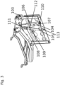
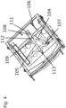
- the seat chassis includes a seat frame 100, a legrest chassis 101 and a legrest extension 102.
- a folding movement of the legrest chassis is shown. If the figures are viewed in reverse order, the legrest chassis folds out.
- the legrest chassis 101 can be pivoted about a geometric pivot axis.
- the pivot axis is defined by the pivot element 103 .
- the pivoting movement of the legrest chassis 101 is triggered by the seat frame 100 being moved forwards, ie towards the legrests chassis 101, or backwards, ie away from the legrests chassis 101.
- the legrest chassis 101 is folded.
- the legrest chassis 101 is unfolded.
- the seat chassis includes a first strut 104 , a second strut 105 and a third strut 106 .
- the second strut 105 is connected to the seat frame 100 via the third strut 106 .
- the first strut 104 can be rotated about a first pivot point 107 and also has a first elongated hole 109 , a first guide element 108 and a cantilever 110 .
- the third strut 106 is connected to the boom 110 .
- the second strut 105 can be rotated about a second pivot point 113 and has a second elongated hole 111 and a second guide element 112 .
- the second slot 111 is open on one side. This has the advantage that when assembling the seat furniture chassis, the first guide element 108 can be inserted into the elongated hole without any further effort.
- the third strut 106 is pushed forward due to its attachment to the seat frame 100, so that it exerts a force on the bracket 110 to which it is connected. This force triggers a pivoting of the first strut 104 about the first pivot point 107 . Due to the arrangement of the second guide element 112 in the first slot 109, the Due to the curved shape of the slot 109 and the arrangement of the first guide element 108 in the second slot 111, the second strut 105 is pivoted about the second pivot point 113 and pulled in the direction of the legrest chassis 101.
- legrest extension 102 is fully retracted. This is particularly advantageous in this position since the legrest chassis 101 is at the position with the smallest distance between the seat frame 100 and the floor surface on which the chair chassis is standing. In order to create a comparatively long support surface for a user's legs with a comparatively small installation space, it is advantageous for the leg support extension 102 to be completely retracted in this position.
- the legrest extension 102 is slightly extended again to tighten a fabric with which the legrest extension 102 and the legrest chassis 101 may be covered. This reduces the risk of unwanted creases in the fabric when the legrest chassis 101 is folded. This is achieved by moving the end of the third strut 106, which is connected to the seat frame 100, in a horizontal direction over the pivot axis of the legrest chassis. After this movement, the third strut 106 pulls on the arm 110 as the legrest chassis 101 folds in further, so that the legrest extension 102 is extended.
Landscapes
- Health & Medical Sciences (AREA)
- Dentistry (AREA)
- General Health & Medical Sciences (AREA)
- Passenger Equipment (AREA)
- Seats For Vehicles (AREA)
- Chairs For Special Purposes, Such As Reclining Chairs (AREA)
- Mattresses And Other Support Structures For Chairs And Beds (AREA)
- Chair Legs, Seat Parts, And Backrests (AREA)
- Legs For Furniture In General (AREA)
Description
- Die vorliegende Erfindung betrifft ein Sitzmöbelchassis gemäß dem Oberbegriff des Anspruchs 1.
- Aus dem Stand der Technik sind Sitzmöbelchassis mit einem schwenkbaren Beinstützenchassis bekannt. Das Beinstützenchassis lässt sich ein- und ausklappen, um entweder vom Benutzer als Beinstütze verwendet zu werden oder aber platzsparend unterhalb der Sitzfläche verstaut zu werden, wenn es nicht benötigt wird. Es sind außerdem Beinstützenverlängerungen bekannt, die die Beinstütze im ausgeklappten Zustand des Beinstützenchassis verlängern und im eingeklappten Zustand des Beinstützenchassis eingefahren sind.
- Die
DE 20 2006 014 927 U1 offenbart eine Fußstütze für Sofas und Sessel, die durch ein Paar paralleler, schwenkbarer Schienen befestigt ist. Sie kann auf diesen Schienen gleiten, wobei ihre Position durch zwei zusammenwirkende Hebel gesteuert wird, von denen einer am Sitz und der andere an der Fußstütze befestigt ist. - Demgegenüber liegt der vorliegenden Erfindung die Aufgabe zugrunde, ein Sitzmöbelchassis mit einer verbesserten Ausfahrmechanik für die Beinstützenverlängerung zu schaffen.
- Diese Aufgabe wird durch ein Sitzmöbelchassis gemäß Anspruch 1 gelöst. Ausführungsformen der Erfindung sind in den abhängigen Ansprüchen angegeben.
- Das Sitzmöbelchassis umfasst einen Sitzflächenrahmen, ein daran schwenkbar angeordnetes Beinstützenchassis und eine am Beinstützenchassis angeordnete ein- und ausfahrbare Beinstützenverlängerung. Unter einem Sitzflächenrahmen wird dabei im Rahmen dieser Beschreibung ein Rahmen verstanden, auf dem Polster angeordnet werden können, die dann als Sitzfläche für einen Benutzer genutzt werden können.
- Das Beinstützenchassis ist von einer ausgeklappten Position in eine eingeklappte Position und umgekehrt verschwenkbar. Die Beinstützenverlängerung ist über eine erste und eine zweite Strebe mit dem Beinstützenchassis verbunden. Die erste Strebe weist ein Langloch und ein erstes Führungselement auf. Die zweite Strebe weist ein zweites Langloch und ein zweites Führungselement auf. Das zweite Führungselement ist verschiebbar im ersten Langloch angeordnet. Das erste Führungselement ist verschiebbar im zweiten Langloch angeordnet.
- Durch die Führung der Führungselemente in den Langlöchern wird ein besonders sanftes Aus- und Einfahren der Beinstützenverlängerung erreicht. Aufgrund der Bewegungsmöglichkeit der Führungselemente in den Langlöchern kann die Beinstützenverlängerung bei einem relativ geringen Bauraum um eine relativ große Distanz aus- und eingefahren werden.
- Nach einer Ausführungsform der Erfindung können das erste und das zweite Führungselement jeweils ein Kugellager umfassen. Dies sorgt für eine relativ geringe Reibung, sodass für die Ein- und Ausfahrbewegung der Beinstützenverlängerung relativ wenig Kraft benötigt wird.
- Nach einer Ausführungsform der Erfindung kann das erste Langloch eine gebogene Form aufweisen. Unter einer gebogenen Form wird im Rahmen dieser Beschreibung insbesondere eine Form verstanden, die runde Richtungsänderungen der Begrenzungen des Langlochs aufweist. Aufgrund der gebogenen Form wird das Führungselement vorteilhaft auf einer Bogenform geführt.
- Nach einer Ausführungsform der Erfindung kann die erste Strebe einen Grundkörper aufweisen. Das erste Langloch kann sich in einem Winkel größer als 45° weg von diesem Grundkörper erstrecken. Der Grundkörper definiert dabei im Wesentlichen die Form der Strebe als solche. Durch das von dem Grundkörper weg ragende erste Langloch kann die Beinstützenverlängerung besonders weit ausgefahren werden.
- Nach einer Ausführungsform der Erfindung kann das zweite Langloch ein offenes Ende aufweisen. Dies ist insbesondere vorteilhaft für die Montage des Sitzmöbelchassis. Das erste Führungselement kann ohne großen Aufwand in das offene Ende des zweiten Langlochs eingesetzt werden.
- Nach einer Ausführungsform der Erfindung kann die erste Strebe verschwenkbar relativ zum Beinstützenchassis und zur zweiten Strebe sein.
- Nach einer Ausführungsform der Erfindung kann die zweite Strebe verschwenkbar relativ zur ersten Strebe und zur Beinstützenverlängerung sein.
- Nach einer Ausführungsform der Erfindung kann die erste Strebe um einen ersten Drehpunkt verschwenkbar sein. Die erste Strebe kann am ersten Drehpunkt am Beinstützenchassis befestigt sein.
- Nach einer Ausführungsform der Erfindung kann der erste Drehpunkt ortsfest relativ zum Beinstützenchassis angeordnet sein. Unter dem Begriff "ortsfest" wird dabei im Rahmen dieser Beschreibung verstanden, dass er sich nicht relativ zum Beinstützenchassis bewegt.
- Nach einer Ausführungsform der Erfindung kann die zweite Strebe um einen zweiten Drehpunkt verschwenkbar sein. Die zweite Strebe kann am zweiten Drehpunkt an der Beinstützenverlängerung befestigt sein.
- Nach einer Ausführungsform der Erfindung kann der zweite Drehpunkt ortsfest relativ zur Beinstützenverlängerung sein.
- Nach einer Ausführungsform der Erfindung können bei einer Verschwenkung der ersten Strebe um den ersten Drehpunkt das erste und das zweite Führungselement im ersten beziehungsweise zweiten Langloch bewegt werden.
- Nach einer Ausführungsform der Erfindung kann das zweite Führungselement zwischen dem zweiten Langloch und dem zweiten Drehpunkt angeordnet sein.
- Nach einer Ausführungsform der Erfindung kann das Sitzmöbelchassis eine dritte Strebe umfassen, die an einem ersten Ende schwenkbar am Sitzflächenchassis angeordnet ist. An einem zweiten Ende ist die dritte Strebe mit einem an der ersten Strebe angeordneten Ausleger verbunden. Die dritte Strebe kann beim Einklappen des Beinstützenchassis die erste Strebe auslenken. Dies kann insbesondere erfolgen, indem die dritte Strebe eine Kraft auf den Ausleger ausübt.
- Nach einer Ausführungsform der Erfindung kann der Ausleger um mehr als 90° auf einem geometrischen Kreis um den ersten Drehpunkt von der ersten Strebe beabstandet sein. Der Mittelpunkt des geometrischen Kreises kann dabei durch den ersten Drehpunkt definiert sein. Unter einem geometrischen Kreis wird dabei insbesondere ein nicht als Bauteil vorhandener Kreis verstanden. Der geometrische Kreis kann virtuell sein und lediglich zur Definition der Lage des Auslegers dienen.
- Nach einer Ausführungsform der Erfindung kann das Beinstützenchassis um eine geometrische Drehachse verschwenkbar sein. Das erste Ende der dritten Strebe kann beim Einklappvorgang des Beinstützenchassis in einer horizontalen Richtung über die geometrische Drehachse bewegt werden. Unter der horizontalen Richtung wird dabei im Rahmen dieser Beschreibung eine Richtung verstanden, die beim bestimmungsgemäßen Gebrauch des Sitzmöbelchassis horizontal ist. Zusätzlich zur Bewegung in der horizontalen Richtung kann auch noch eine Bewegungskomponente in einer vertikalen Richtung vorhanden sein.
- Nach einer Ausführungsform der Erfindung kann die Beinstützenverlängerung zu einem Zeitpunkt während des Einklappvorgangs des Beinstützenchassis weiter eingefahren sein als im eingeklappten Zustand des Beinstützenchassis. Dies ist insbesondere vorteilhaft, da die Beinstützenverlängerung möglichst weit eingefahren sein sollte, wenn das Beinstützenchassis so weit eingeklappt ist, dass es auf der kürzesten Strecke zwischen dem vorderen Ende des Sitzflächenrahmens und der Bodenoberfläche, auf dem das Sitzmöbelchassis steht, liegt. An diesem Punkt soll es vermieden werden, dass das Beinstützenchassis oder die Beinstützenverlängerung die Bodenoberfläche berührt. Es ist vorteilhaft, die Beinstützenverlängerung beim Einklappen danach noch einmal ein bisschen auszufahren, da dann der Stoff, mit dem das Beinstützenchassis und eventuell auch die Beinstützenverlängerung bezogen ist, gespannt wird, sodass das Risiko für unerwünschte Falten im Stoff verringert wird.
- Weitere Merkmale und Vorteile der vorliegenden Erfindung werden deutlich anhand der nachfolgenden Beschreibung bevorzugter Ausführungsbeispiele unter Bezugnahme auf die beiliegenden Abbildungen. Dabei werden für gleiche oder ähnliche Bauteile und für Bauteile mit gleichen oder ähnlichen Funktionen die gleichen Bezugszeichen verwendet. Darin zeigen:
- Fig. 1
- eine schematische perspektivische Ansicht eines Sitzmöbelchassis nach einer Ausführungsform der Erfindung mit ausgeklapptem Beinstützenchassis und ausgefahrener Beinstützenverlängerung;
- Fig. 2
- eine schematische perspektivische Ansicht des Sitzmöbelchassis aus
Fig. 1 mit teilweise eingeklapptem Beinstützenchassis und teilweise eingefahrener Beinstützenverlängerung; - Fig. 3
- eine schematische perspektivische Ansicht des Sitzmöbelchassis aus
Fig. 1 mit im Vergleich zuFig. 2 weiter eingeklapptem Beinstützenchassis und ganz eingefahrener Beinstützenverlängerung; und - Fig. 4
- eine schematische perspektivische Ansicht des Sitzmöbelchassis aus
Fig. 1 mit komplett eingeklapptem Beinstützenchassis und teilweise im Vergleich zuFig. 3 wieder etwas ausgefahrener Beinstützenverlängerung. - Das Sitzmöbelchassis umfasst einen Sitzflächenrahmen 100, ein Beinstützenchassis 101 und eine Beinstützenverlängerung 102. In den
Figuren 1 bis 4 ist eine Einklappbewegung des Beinstützenchassis dargestellt. Bei Betrachtung der Figuren in umgekehrter Reihenfolge ergibt sich eine Ausklappbewegung des Beinstützenchassis. - Das Beinstützenchassis 101 ist um eine geometrische Schwenkachse schwenkbar. Die Schwenkachse wird dabei durch das Schwenkelement 103 definiert. Die Schwenkbewegung des Beinstützenchassis 101 wird ausgelöst, indem der Sitzflächenrahmen 100 nach vorne, also in Richtung des Beinstützenchassis 101, oder nach hinten, also weg vom Beinstützenchassis 101, bewegt wird. Bei einer Bewegung des Sitzflächenrahmens 100 nach vorne wird das Beinstützenchassis 101 eingeklappt. Bei einer Bewegung des Sitzflächenrahmens 100 nach hinten wird das Beinstützenchassis 101 ausgeklappt.
- Das Sitzmöbelchassis umfasst eine erste Strebe 104, eine zweite Strebe 105 und eine dritte Strebe 106. Die Beinstützenverlängerung 102 ist über die erste Strebe 104 und die zweite Strebe 105 mit dem Beinstützenchassis 101 verbunden. Die zweite Strebe 105 ist über die dritte Strebe 106 mit dem Sitzflächenrahmen 100 verbunden. Die erste Strebe 104 ist um einen ersten Drehpunkt 107 drehbar und weist außerdem ein erstes Langloch 109, ein erstes Führungselement 108 und einen Ausleger 110 auf. Die dritte Strebe 106 ist mit dem Ausleger 110 verbunden. Die zweite Strebe 105 ist um einen zweiten Drehpunkt 113 drehbar und weist ein zweites Langloch 111 und ein zweites Führungselement 112 auf.
- Das zweite Langloch 111 ist einseitig offen. Dies hat den Vorteil, dass bei der Montage des Sitzmöbelchassis das erste Führungselement 108 ohne weiteren Aufwand in das Langloch eingesetzt werden kann.
- Während der in den
Figuren 1 bis 3 dargestellten Einklappbewegung des Beinstützenchassis 101 wird die dritte Strebe 106 aufgrund ihrer Befestigung am Sitzflächenrahmen 100 nach vorne geschoben, sodass sie eine Kraft auf den Ausleger 110 ausübt, mit dem sie verbunden ist. Diese Kraft löst eine Verschwenkung der ersten Strebe 104 um den ersten Drehpunkt 107 aus. Aufgrund der Anordnung des zweiten Führungselements 112 im ersten Langloch 109, der gebogenen Form des Langlochs 109 und der Anordnung des ersten Führungselements 108 im zweiten Langloch 111 wird dabei die zweite Strebe 105 um den zweiten Drehpunkt 113 verschwenkt und in Richtung des Beinstützenchassis 101 gezogen. - In
Figur 3 ist die Beinstützenverlängerung 102 komplett eingefahren. Dies ist in dieser Stellung besonders vorteilhaft, da sich das Beinstützenchassis 101 an der Position mit dem geringsten Abstand zwischen dem Sitzflächenrahmen 100 und der Bodenoberfläche, auf der das Sitzmöbelchassis steht, befindet. Um bei vergleichsweise geringem Bauraum eine vergleichsweise lange Abstützfläche für die Beine eines Benutzers zu schaffen, ist es vorteilhaft, dass die Beinstützenverlängerung 102 in dieser Position komplett eingefahren ist. - Wenn das Beinstützenchassis 101 weiter eingeklappt wird, wird die Beinstützenverlängerung 102 wieder etwas ausgefahren, um einen Stoff, mit dem die Beinstützenverlängerung 102 und das Beinstützenchassis 101 bezogen sein können, zu straffen. So wird das Risiko für unerwünschte Falten im Stoff bei eingeklapptem Beinstützenchassis 101 verringert. Dies wird dadurch erreicht, dass das Ende der dritten Strebe 106, das mit dem Sitzflächenrahmen 100 verbunden ist, in horizontaler Richtung über die Schwenkachse des Beinstützenchassis bewegt wird. Nach dieser Bewegung zieht die dritte Strebe 106 beim weiteren Einklappen des Beinstützenchassis 101 am Ausleger 110, sodass die Beinstützenverlängerung 102 ausgefahren wird.
Claims (15)
- Sitzmöbelchassis, umfassend einen Sitzflächenrahmen (100), ein daran schwenkbar angeordnetes Beinstützenchassis (101) und eine ein- und ausfahrbare Beinstützenverlängerung (102), wobei die Beinstützenverlängerung (102) am Beinstützenchassis (101) angeordnet ist, wobei das Beinstützenchassis (101) von einer ausgeklappten Position in eine eingeklappte Position verschwenkbar ist, wobei die Beinstützenverlängerung (102) über eine erste Strebe (104) und eine zweite Strebe (105) mit dem Beinstützenchassis (101) verbunden ist, wobei die erste Strebe (104) ein erstes Führungselement (108) aufweist, und wobei die zweite Strebe (105) ein zweites Langloch (111) und ein zweites Führungselement (112) aufweist, wobei das erste Führungselement (108) verschiebbar in dem zweiten Langloch (111) angeordnet ist, dadurch gekennzeichnet, dass die erste Strebe (104) ein erstes Langloch (109) aufweist und dass das zweite Führungselement (112) verschiebbar in dem ersten Langloch (109) angeordnet ist.
- Sitzmöbelchassis nach Anspruch 1, dadurch gekennzeichnet, dass das erste Führungselement (108) und das zweite Führungselement (112) jeweils ein Kugellager umfassen.
- Sitzmöbelchassis nach einem der vorherigen Ansprüche, dadurch gekennzeichnet, dass das erste Langloch (109) eine gebogene Form aufweist.
- Sitzmöbelchassis nach einem der vorherigen Ansprüche, dadurch gekennzeichnet, dass die erste Strebe (104) einen Grundkörper aufweist, wobei sich das erste Langloch (109) in einem Winkel größer als 45° weg vom Grundkörper erstreckt.
- Sitzmöbelchassis nach einem der vorherigen Ansprüche, dadurch gekennzeichnet, dass das zweite Langloch (111) ein offenes Ende aufweist.
- Sitzmöbelchassis nach einem der vorherigen Ansprüche, dadurch gekennzeichnet, dass die erste Strebe (104) verschwenkbar relativ zum Beinstützenchassis (101) und zur zweiten Strebe (105) ist.
- Sitzmöbelchassis nach einem der vorherigen Ansprüche, dadurch gekennzeichnet, dass die zweite Strebe (105) verschwenkbar relativ zur ersten Strebe (104) und zur Beinstützenverlängerung (102) ist.
- Sitzmöbelchassis nach einem der vorherigen Ansprüche, dadurch gekennzeichnet, dass die erste Strebe (104) um einen ersten Drehpunkt (107) verschwenkbar ist, wobei die erste Strebe (104) am ersten Drehpunkt (107) am Beinstützenchassis (101) befestigt ist.
- Sitzmöbelchassis nach dem vorherigen Anspruch, dadurch gekennzeichnet, dass der erste Drehpunkt (107) ortsfest relativ zum Beinstützenchassis (101) angeordnet ist.
- Sitzmöbelchassis nach einem der vorherigen Ansprüche, dadurch gekennzeichnet, dass die zweite Strebe (105) um einen zweiten Drehpunkt (113) verschwenkbar ist, wobei die zweite Strebe (105) am zweiten Drehpunkt (113) an der Beinstützenverlängerung (102) befestigt ist.
- Sitzmöbelchassis nach einem der vorherigen Ansprüche, dadurch gekennzeichnet, dass bei einer Verschwenkung der ersten Strebe (104) um den ersten Drehpunkt (107) das erste Führungselement (108) und das zweite Führungselement (112) im ersten Langloch (109) bzw. zweiten Langloch (111) bewegt werden.
- Sitzmöbelchassis nach einem der vorherigen Ansprüche, dadurch gekennzeichnet, dass das zweite Führungselement (112) zwischen dem zweiten Langloch (111) und dem zweiten Drehpunkt (113) angeordnet ist.
- Sitzmöbelchassis nach einem der vorherigen Ansprüche, dadurch gekennzeichnet, dass das Sitzmöbelchassis eine dritte Strebe (106) umfasst, wobei die dritte Strebe (106) an einem ersten Ende schwenkbar am Sitzflächenrahmen (100) angeordnet ist, und wobei die dritte Strebe (106) an einem zweiten Ende mit einem an der ersten Strebe (104) angeordneten Ausleger (110) verbunden ist, und wobei die dritte Strebe (106) beim Einklappen des Beinstützenchassis (101) die erste Strebe (104) auslenkt.
- Sitzmöbelchassis nach einem der vorherigen Ansprüche, dadurch gekennzeichnet, dass das Beinstützenchassis (101) um eine geometrische Drehachse verschwenkbar ist, wobei das erste Ende der dritten Strebe (106) beim Einklappvorgang des Beinstützenchassis (101) in einer horizontalen Richtung über die geometrische Drehachse bewegt wird.
- Sitzmöbelchassis nach einem der vorherigen Ansprüche, dadurch gekennzeichnet, dass die Beinstützenverlängerung (102) zu einem Zeitpunkt während des Einklappvorgangs des Beinstützenchassis (101) weiter eingefahren ist als im eingeklappten Zustand des Beinstützenchassis (101).
Applications Claiming Priority (2)
| Application Number | Priority Date | Filing Date | Title |
|---|---|---|---|
| DE202019104069.6U DE202019104069U1 (de) | 2019-07-23 | 2019-07-23 | Sitzmöbelchassis |
| PCT/EP2020/070702 WO2021013896A1 (de) | 2019-07-23 | 2020-07-22 | Sitzmöbelchassis |
Publications (3)
| Publication Number | Publication Date |
|---|---|
| EP4003097A1 EP4003097A1 (de) | 2022-06-01 |
| EP4003097B1 true EP4003097B1 (de) | 2023-06-28 |
| EP4003097C0 EP4003097C0 (de) | 2023-06-28 |
Family
ID=67701973
Family Applications (1)
| Application Number | Title | Priority Date | Filing Date |
|---|---|---|---|
| EP20750189.1A Active EP4003097B1 (de) | 2019-07-23 | 2020-07-22 | Sitzmöbelchassis |
Country Status (7)
| Country | Link |
|---|---|
| US (1) | US11930937B2 (de) |
| EP (1) | EP4003097B1 (de) |
| CN (1) | CN113939215B (de) |
| DE (1) | DE202019104069U1 (de) |
| ES (1) | ES2953143T3 (de) |
| PL (1) | PL4003097T3 (de) |
| WO (1) | WO2021013896A1 (de) |
Families Citing this family (4)
| Publication number | Priority date | Publication date | Assignee | Title |
|---|---|---|---|---|
| CN113273842B (zh) * | 2021-06-11 | 2025-06-24 | 广东佳居家具有限公司 | 一种支架结构以及座椅 |
| CN116439530B (zh) * | 2023-05-05 | 2026-02-17 | 顾家家居股份有限公司 | 一种腿托装置及坐具 |
| CN116671742A (zh) * | 2023-07-14 | 2023-09-01 | 顾家家居股份有限公司 | 一种多功能铁架及坐具 |
| US12551017B2 (en) * | 2023-08-25 | 2026-02-17 | Textron Innovations Inc. | Leg rest extension mechanism and method for operating the leg rest extension mechanism |
Family Cites Families (17)
| Publication number | Priority date | Publication date | Assignee | Title |
|---|---|---|---|---|
| US3054640A (en) * | 1959-11-24 | 1962-09-18 | Lorenz Anton | Multiple position reclining chair |
| FR2619495A1 (fr) * | 1987-07-31 | 1989-02-24 | Lafer Percival | Chaise longue |
| FR2643870A1 (fr) * | 1989-03-01 | 1990-09-07 | Sicma Earo Seat | Siege de passagers convertible a tablette escamotable |
| US5857739A (en) * | 1996-06-10 | 1999-01-12 | Nepsco, Inc. | Chair |
| DE10250075A1 (de) * | 2002-10-25 | 2004-05-13 | Hans-Peter Barthelt | Drehbett mit verbessertem Drehscharnier |
| DE202006014927U1 (de) * | 2006-09-28 | 2007-01-11 | Olsberg Hermann Everken Gmbh | Schwenkbare Stütze für ein Sitzmöbel |
| DE202007004695U1 (de) * | 2007-03-30 | 2008-08-14 | Olsberg Hermann Everken Gmbh | Sitzmöbel |
| DE102009037162B4 (de) * | 2009-08-03 | 2012-08-02 | Kintec-Solution Gmbh | Sitzmöbelstück |
| US8366188B2 (en) * | 2010-04-13 | 2013-02-05 | La-Z-Boy Incorporated | Release system for furniture member leg rest assemblies |
| US10631652B2 (en) * | 2016-03-11 | 2020-04-28 | Innotec Motion GmbH | Seating furniture chassis with a retractable and extendable footrest |
| EP3284370B1 (de) * | 2016-08-16 | 2019-03-13 | Beheermaatschappij Vermeulen Beesd B.V. | Beschlag für ein sitzmöbelstück und sitzmöbelstück mit einem solchen beschlag |
| KR101827419B1 (ko) * | 2016-10-17 | 2018-02-09 | 현대다이모스(주) | 뒤틀림 방지 기능을 갖는 레그레스트 |
| CN207477253U (zh) * | 2017-05-10 | 2018-06-12 | 永艺家具股份有限公司 | 折叠式腿托机构及坐具 |
| CN109984504A (zh) * | 2018-09-20 | 2019-07-09 | 永艺家具股份有限公司 | 一种折叠式搁脚机构及座椅 |
| US10849432B2 (en) * | 2018-11-14 | 2020-12-01 | Gary Michael Pritchard | Methods and apparatus for variable user position seating |
| DE202019101920U1 (de) * | 2019-04-03 | 2020-07-06 | Innotec Motion GmbH | Sitzmöbelchassis |
| US12022951B2 (en) * | 2021-12-28 | 2024-07-02 | Dongguan Weihong Smart Home Technology Co., Ltd. | Folding chair device |
-
2019
- 2019-07-23 DE DE202019104069.6U patent/DE202019104069U1/de active Active
-
2020
- 2020-07-22 ES ES20750189T patent/ES2953143T3/es active Active
- 2020-07-22 PL PL20750189.1T patent/PL4003097T3/pl unknown
- 2020-07-22 WO PCT/EP2020/070702 patent/WO2021013896A1/de not_active Ceased
- 2020-07-22 EP EP20750189.1A patent/EP4003097B1/de active Active
- 2020-07-22 CN CN202080041515.XA patent/CN113939215B/zh active Active
-
2021
- 2021-11-11 US US17/524,246 patent/US11930937B2/en active Active
Also Published As
| Publication number | Publication date |
|---|---|
| US20220061533A1 (en) | 2022-03-03 |
| CN113939215A (zh) | 2022-01-14 |
| PL4003097T3 (pl) | 2023-10-23 |
| ES2953143T3 (es) | 2023-11-08 |
| US11930937B2 (en) | 2024-03-19 |
| EP4003097A1 (de) | 2022-06-01 |
| EP4003097C0 (de) | 2023-06-28 |
| CN113939215B (zh) | 2025-07-15 |
| DE202019104069U1 (de) | 2019-08-02 |
| WO2021013896A1 (de) | 2021-01-28 |
Similar Documents
| Publication | Publication Date | Title |
|---|---|---|
| DE60110488T2 (de) | Ausziehfussstütze, insbesondere für Sessel, Sofas und dergleichen | |
| EP2356922B1 (de) | Sitz-/Liegemöbelchassis | |
| WO2021013896A1 (de) | Sitzmöbelchassis | |
| EP3965617B1 (de) | Sitzmöbel mit zweimotoriger wallaway-funktion | |
| EP3965616B1 (de) | Sitzmöbel mit wallaway-funktion und ausschwenkbarem fussteil | |
| EP3426094B1 (de) | Sitzmöbelchassis mit einer ein- und ausfahrbaren fussstütze | |
| DE102013104760B3 (de) | Fahrzeugsitz, insbesondere für ein Kraftfahrzeug | |
| EP2996516A1 (de) | EIN- UND AUSKLAPPVORRICHTUNG FÜR EINE FUß- UND/ODER BEINSTÜTZE EINES SITZ- UND/ODER LIEGEMÖBELS | |
| EP3284370B1 (de) | Beschlag für ein sitzmöbelstück und sitzmöbelstück mit einem solchen beschlag | |
| EP3228220B1 (de) | Sitz-/liegemöbel | |
| DE112008002844B4 (de) | Aufhängungsmechanismus mit integriertem Verkippungsmechanismus | |
| EP3945942B1 (de) | Sitzmöbelchassis | |
| EP2638827A1 (de) | Schwenkbeschlag zum Verstellen eines Polstermöbels | |
| DE202018100112U1 (de) | Chassis für ein Sitz- und/oder Liegemöbel | |
| EP3426095B1 (de) | System umfassed ein fussstützenchassis und ein sitzmöbelchassis | |
| DE2601691C3 (de) | Hebelverstellgetriebe für Sitz-Liegesessel | |
| DE202012100960U1 (de) | Sitz-/Liegemöbel | |
| DE1404660B2 (de) | Verstellsessel | |
| EP4266949B1 (de) | Sitzmöbel mit teleskopierbarem beinauflagenelement | |
| EP2907412A1 (de) | Sitzmöbel mit ausschwenkbarer Fußstütze | |
| EP1754426B1 (de) | Sitzmöbel mit ausziehbarer Beinauflage | |
| DE202016104974U1 (de) | Sitzmöbel mit ausschwenkbarer Fußstütze | |
| DE202016101718U1 (de) | Faltsessel | |
| DE3127310C2 (de) | ||
| DE102016116893A1 (de) | Sitzmöbel mit ausschwenkbarer Fußstütze |
Legal Events
| Date | Code | Title | Description |
|---|---|---|---|
| STAA | Information on the status of an ep patent application or granted ep patent |
Free format text: STATUS: UNKNOWN |
|
| STAA | Information on the status of an ep patent application or granted ep patent |
Free format text: STATUS: THE INTERNATIONAL PUBLICATION HAS BEEN MADE |
|
| PUAI | Public reference made under article 153(3) epc to a published international application that has entered the european phase |
Free format text: ORIGINAL CODE: 0009012 |
|
| STAA | Information on the status of an ep patent application or granted ep patent |
Free format text: STATUS: REQUEST FOR EXAMINATION WAS MADE |
|
| 17P | Request for examination filed |
Effective date: 20220223 |
|
| AK | Designated contracting states |
Kind code of ref document: A1 Designated state(s): AL AT BE BG CH CY CZ DE DK EE ES FI FR GB GR HR HU IE IS IT LI LT LU LV MC MK MT NL NO PL PT RO RS SE SI SK SM TR |
|
| DAV | Request for validation of the european patent (deleted) | ||
| DAX | Request for extension of the european patent (deleted) | ||
| GRAP | Despatch of communication of intention to grant a patent |
Free format text: ORIGINAL CODE: EPIDOSNIGR1 |
|
| STAA | Information on the status of an ep patent application or granted ep patent |
Free format text: STATUS: GRANT OF PATENT IS INTENDED |
|
| INTG | Intention to grant announced |
Effective date: 20230112 |
|
| GRAS | Grant fee paid |
Free format text: ORIGINAL CODE: EPIDOSNIGR3 |
|
| GRAA | (expected) grant |
Free format text: ORIGINAL CODE: 0009210 |
|
| STAA | Information on the status of an ep patent application or granted ep patent |
Free format text: STATUS: THE PATENT HAS BEEN GRANTED |
|
| AK | Designated contracting states |
Kind code of ref document: B1 Designated state(s): AL AT BE BG CH CY CZ DE DK EE ES FI FR GB GR HR HU IE IS IT LI LT LU LV MC MK MT NL NO PL PT RO RS SE SI SK SM TR |
|
| REG | Reference to a national code |
Ref country code: CH Ref legal event code: EP |
|
| REG | Reference to a national code |
Ref country code: AT Ref legal event code: REF Ref document number: 1581933 Country of ref document: AT Kind code of ref document: T Effective date: 20230715 |
|
| REG | Reference to a national code |
Ref country code: IE Ref legal event code: FG4D Free format text: LANGUAGE OF EP DOCUMENT: GERMAN |
|
| REG | Reference to a national code |
Ref country code: DE Ref legal event code: R096 Ref document number: 502020003975 Country of ref document: DE |
|
| U01 | Request for unitary effect filed |
Effective date: 20230711 |
|
| U07 | Unitary effect registered |
Designated state(s): AT BE BG DE DK EE FI FR IT LT LU LV MT NL PT SE SI Effective date: 20230721 |
|
| REG | Reference to a national code |
Ref country code: NO Ref legal event code: T2 Effective date: 20230628 |
|
| REG | Reference to a national code |
Ref country code: LT Ref legal event code: MG9D |
|
| REG | Reference to a national code |
Ref country code: ES Ref legal event code: FG2A Ref document number: 2953143 Country of ref document: ES Kind code of ref document: T3 Effective date: 20231108 |
|
| PG25 | Lapsed in a contracting state [announced via postgrant information from national office to epo] |
Ref country code: RS Free format text: LAPSE BECAUSE OF FAILURE TO SUBMIT A TRANSLATION OF THE DESCRIPTION OR TO PAY THE FEE WITHIN THE PRESCRIBED TIME-LIMIT Effective date: 20230628 Ref country code: HR Free format text: LAPSE BECAUSE OF FAILURE TO SUBMIT A TRANSLATION OF THE DESCRIPTION OR TO PAY THE FEE WITHIN THE PRESCRIBED TIME-LIMIT Effective date: 20230628 Ref country code: GR Free format text: LAPSE BECAUSE OF FAILURE TO SUBMIT A TRANSLATION OF THE DESCRIPTION OR TO PAY THE FEE WITHIN THE PRESCRIBED TIME-LIMIT Effective date: 20230929 |
|
| U20 | Renewal fee for the european patent with unitary effect paid |
Year of fee payment: 4 Effective date: 20231031 |
|
| PG25 | Lapsed in a contracting state [announced via postgrant information from national office to epo] |
Ref country code: SK Free format text: LAPSE BECAUSE OF FAILURE TO SUBMIT A TRANSLATION OF THE DESCRIPTION OR TO PAY THE FEE WITHIN THE PRESCRIBED TIME-LIMIT Effective date: 20230628 |
|
| PG25 | Lapsed in a contracting state [announced via postgrant information from national office to epo] |
Ref country code: IS Free format text: LAPSE BECAUSE OF FAILURE TO SUBMIT A TRANSLATION OF THE DESCRIPTION OR TO PAY THE FEE WITHIN THE PRESCRIBED TIME-LIMIT Effective date: 20231028 |
|
| PG25 | Lapsed in a contracting state [announced via postgrant information from national office to epo] |
Ref country code: SM Free format text: LAPSE BECAUSE OF FAILURE TO SUBMIT A TRANSLATION OF THE DESCRIPTION OR TO PAY THE FEE WITHIN THE PRESCRIBED TIME-LIMIT Effective date: 20230628 Ref country code: SK Free format text: LAPSE BECAUSE OF FAILURE TO SUBMIT A TRANSLATION OF THE DESCRIPTION OR TO PAY THE FEE WITHIN THE PRESCRIBED TIME-LIMIT Effective date: 20230628 Ref country code: RO Free format text: LAPSE BECAUSE OF FAILURE TO SUBMIT A TRANSLATION OF THE DESCRIPTION OR TO PAY THE FEE WITHIN THE PRESCRIBED TIME-LIMIT Effective date: 20230628 Ref country code: IS Free format text: LAPSE BECAUSE OF FAILURE TO SUBMIT A TRANSLATION OF THE DESCRIPTION OR TO PAY THE FEE WITHIN THE PRESCRIBED TIME-LIMIT Effective date: 20231028 Ref country code: CZ Free format text: LAPSE BECAUSE OF FAILURE TO SUBMIT A TRANSLATION OF THE DESCRIPTION OR TO PAY THE FEE WITHIN THE PRESCRIBED TIME-LIMIT Effective date: 20230628 |
|
| REG | Reference to a national code |
Ref country code: CH Ref legal event code: PL |
|
| PG25 | Lapsed in a contracting state [announced via postgrant information from national office to epo] |
Ref country code: MC Free format text: LAPSE BECAUSE OF FAILURE TO SUBMIT A TRANSLATION OF THE DESCRIPTION OR TO PAY THE FEE WITHIN THE PRESCRIBED TIME-LIMIT Effective date: 20230628 |
|
| PG25 | Lapsed in a contracting state [announced via postgrant information from national office to epo] |
Ref country code: MC Free format text: LAPSE BECAUSE OF FAILURE TO SUBMIT A TRANSLATION OF THE DESCRIPTION OR TO PAY THE FEE WITHIN THE PRESCRIBED TIME-LIMIT Effective date: 20230628 |
|
| REG | Reference to a national code |
Ref country code: DE Ref legal event code: R097 Ref document number: 502020003975 Country of ref document: DE |
|
| REG | Reference to a national code |
Ref country code: IE Ref legal event code: MM4A |
|
| PG25 | Lapsed in a contracting state [announced via postgrant information from national office to epo] |
Ref country code: CH Free format text: LAPSE BECAUSE OF NON-PAYMENT OF DUE FEES Effective date: 20230731 |
|
| PLBE | No opposition filed within time limit |
Free format text: ORIGINAL CODE: 0009261 |
|
| STAA | Information on the status of an ep patent application or granted ep patent |
Free format text: STATUS: NO OPPOSITION FILED WITHIN TIME LIMIT |
|
| 26N | No opposition filed |
Effective date: 20240402 |
|
| PG25 | Lapsed in a contracting state [announced via postgrant information from national office to epo] |
Ref country code: IE Free format text: LAPSE BECAUSE OF NON-PAYMENT OF DUE FEES Effective date: 20230722 |
|
| PG25 | Lapsed in a contracting state [announced via postgrant information from national office to epo] |
Ref country code: IE Free format text: LAPSE BECAUSE OF NON-PAYMENT OF DUE FEES Effective date: 20230722 |
|
| U20 | Renewal fee for the european patent with unitary effect paid |
Year of fee payment: 5 Effective date: 20240731 |
|
| GBPC | Gb: european patent ceased through non-payment of renewal fee |
Effective date: 20240722 |
|
| PG25 | Lapsed in a contracting state [announced via postgrant information from national office to epo] |
Ref country code: GB Free format text: LAPSE BECAUSE OF NON-PAYMENT OF DUE FEES Effective date: 20240722 |
|
| PG25 | Lapsed in a contracting state [announced via postgrant information from national office to epo] |
Ref country code: CY Free format text: LAPSE BECAUSE OF FAILURE TO SUBMIT A TRANSLATION OF THE DESCRIPTION OR TO PAY THE FEE WITHIN THE PRESCRIBED TIME-LIMIT; INVALID AB INITIO Effective date: 20200722 |
|
| PG25 | Lapsed in a contracting state [announced via postgrant information from national office to epo] |
Ref country code: HU Free format text: LAPSE BECAUSE OF FAILURE TO SUBMIT A TRANSLATION OF THE DESCRIPTION OR TO PAY THE FEE WITHIN THE PRESCRIBED TIME-LIMIT; INVALID AB INITIO Effective date: 20200722 |
|
| U20 | Renewal fee for the european patent with unitary effect paid |
Year of fee payment: 6 Effective date: 20250731 |
|
| PGFP | Annual fee paid to national office [announced via postgrant information from national office to epo] |
Ref country code: ES Payment date: 20250827 Year of fee payment: 6 |
|
| PGFP | Annual fee paid to national office [announced via postgrant information from national office to epo] |
Ref country code: NO Payment date: 20250725 Year of fee payment: 6 |
|
| PGFP | Annual fee paid to national office [announced via postgrant information from national office to epo] |
Ref country code: TR Payment date: 20250716 Year of fee payment: 6 Ref country code: PL Payment date: 20250711 Year of fee payment: 6 |
|
| U1N | Appointed representative for the unitary patent procedure changed after the registration of the unitary effect |
Representative=s name: FRITZ PATENT- UND RECHTSANWAELTE PARTMBB; DE |