EP4003107B1 - Système et procédé de filtrage de boisson chaude - Google Patents
Système et procédé de filtrage de boisson chaude Download PDFInfo
- Publication number
- EP4003107B1 EP4003107B1 EP20847387.6A EP20847387A EP4003107B1 EP 4003107 B1 EP4003107 B1 EP 4003107B1 EP 20847387 A EP20847387 A EP 20847387A EP 4003107 B1 EP4003107 B1 EP 4003107B1
- Authority
- EP
- European Patent Office
- Prior art keywords
- filter
- water
- reservoir
- housing
- container
- Prior art date
- Legal status (The legal status is an assumption and is not a legal conclusion. Google has not performed a legal analysis and makes no representation as to the accuracy of the status listed.)
- Active
Links
Images






Classifications
-
- A—HUMAN NECESSITIES
- A47—FURNITURE; DOMESTIC ARTICLES OR APPLIANCES; COFFEE MILLS; SPICE MILLS; SUCTION CLEANERS IN GENERAL
- A47J—KITCHEN EQUIPMENT; COFFEE MILLS; SPICE MILLS; APPARATUS FOR MAKING BEVERAGES
- A47J31/00—Apparatus for making beverages
- A47J31/24—Coffee-making apparatus in which hot water is passed through the filter under pressure, i.e. in which the coffee grounds are extracted under pressure
- A47J31/34—Coffee-making apparatus in which hot water is passed through the filter under pressure, i.e. in which the coffee grounds are extracted under pressure with hot water under liquid pressure
- A47J31/36—Coffee-making apparatus in which hot water is passed through the filter under pressure, i.e. in which the coffee grounds are extracted under pressure with hot water under liquid pressure with mechanical pressure-producing means
- A47J31/3666—Coffee-making apparatus in which hot water is passed through the filter under pressure, i.e. in which the coffee grounds are extracted under pressure with hot water under liquid pressure with mechanical pressure-producing means whereby the loading of the brewing chamber with the brewing material is performed by the user
-
- A—HUMAN NECESSITIES
- A23—FOODS OR FOODSTUFFS; TREATMENT THEREOF, NOT COVERED BY OTHER CLASSES
- A23F—COFFEE; TEA; THEIR SUBSTITUTES; MANUFACTURE, PREPARATION, OR INFUSION THEREOF
- A23F5/00—Coffee; Coffee substitutes; Preparations thereof
- A23F5/24—Extraction of coffee; Coffee extracts; Making instant coffee
- A23F5/26—Extraction of water soluble constituents
-
- A—HUMAN NECESSITIES
- A47—FURNITURE; DOMESTIC ARTICLES OR APPLIANCES; COFFEE MILLS; SPICE MILLS; SUCTION CLEANERS IN GENERAL
- A47J—KITCHEN EQUIPMENT; COFFEE MILLS; SPICE MILLS; APPARATUS FOR MAKING BEVERAGES
- A47J19/00—Household machines for straining foodstuffs; Household implements for mashing or straining foodstuffs
- A47J19/02—Citrus fruit squeezers; Other fruit juice extracting devices
- A47J19/023—Citrus fruit squeezers; Other fruit juice extracting devices including a pressing cone or reamer
-
- A—HUMAN NECESSITIES
- A47—FURNITURE; DOMESTIC ARTICLES OR APPLIANCES; COFFEE MILLS; SPICE MILLS; SUCTION CLEANERS IN GENERAL
- A47J—KITCHEN EQUIPMENT; COFFEE MILLS; SPICE MILLS; APPARATUS FOR MAKING BEVERAGES
- A47J31/00—Apparatus for making beverages
- A47J31/24—Coffee-making apparatus in which hot water is passed through the filter under pressure, i.e. in which the coffee grounds are extracted under pressure
- A47J31/34—Coffee-making apparatus in which hot water is passed through the filter under pressure, i.e. in which the coffee grounds are extracted under pressure with hot water under liquid pressure
- A47J31/36—Coffee-making apparatus in which hot water is passed through the filter under pressure, i.e. in which the coffee grounds are extracted under pressure with hot water under liquid pressure with mechanical pressure-producing means
- A47J31/3666—Coffee-making apparatus in which hot water is passed through the filter under pressure, i.e. in which the coffee grounds are extracted under pressure with hot water under liquid pressure with mechanical pressure-producing means whereby the loading of the brewing chamber with the brewing material is performed by the user
- A47J31/3676—Cartridges being employed
- A47J31/368—Permeable cartridges being employed
-
- A—HUMAN NECESSITIES
- A47—FURNITURE; DOMESTIC ARTICLES OR APPLIANCES; COFFEE MILLS; SPICE MILLS; SUCTION CLEANERS IN GENERAL
- A47J—KITCHEN EQUIPMENT; COFFEE MILLS; SPICE MILLS; APPARATUS FOR MAKING BEVERAGES
- A47J31/00—Apparatus for making beverages
- A47J31/42—Beverage-making apparatus with incorporated grinding or roasting means for coffee
-
- A—HUMAN NECESSITIES
- A47—FURNITURE; DOMESTIC ARTICLES OR APPLIANCES; COFFEE MILLS; SPICE MILLS; SUCTION CLEANERS IN GENERAL
- A47J—KITCHEN EQUIPMENT; COFFEE MILLS; SPICE MILLS; APPARATUS FOR MAKING BEVERAGES
- A47J31/00—Apparatus for making beverages
- A47J31/44—Parts or details or accessories of beverage-making apparatus
- A47J31/4482—Details allowing to adapt the beverage-making apparatus to the size of the brewing vessel or the beverage container, e.g. with adjustable support for the beverage container or adjustable hot water outlet
-
- A—HUMAN NECESSITIES
- A47—FURNITURE; DOMESTIC ARTICLES OR APPLIANCES; COFFEE MILLS; SPICE MILLS; SUCTION CLEANERS IN GENERAL
- A47J—KITCHEN EQUIPMENT; COFFEE MILLS; SPICE MILLS; APPARATUS FOR MAKING BEVERAGES
- A47J31/00—Apparatus for making beverages
- A47J31/44—Parts or details or accessories of beverage-making apparatus
- A47J31/46—Dispensing spouts, pumps, drain valves or like liquid transporting devices
- A47J31/469—Details of hydraulic circuits
-
- A—HUMAN NECESSITIES
- A47—FURNITURE; DOMESTIC ARTICLES OR APPLIANCES; COFFEE MILLS; SPICE MILLS; SUCTION CLEANERS IN GENERAL
- A47J—KITCHEN EQUIPMENT; COFFEE MILLS; SPICE MILLS; APPARATUS FOR MAKING BEVERAGES
- A47J31/00—Apparatus for making beverages
- A47J31/06—Filters or strainers for coffee or tea makers ; Holders therefor
- A47J31/0647—Filters or strainers for coffee or tea makers ; Holders therefor with means to adjust the brewing chamber volume to accommodate different quantities of brewing material
Definitions
- Conventional brewers of hot beverages such as coffee brewers are available, which brew single servings of coffee (e.g. Keurig ® coffee brewer). Additionally, other conventional coffee brewers are available, which brew multiple servings of coffee (e.g. a pot of coffee, such as 10-12 cups). These conventional coffee brewers typically involve placement of a coffee filter in a receptacle (e.g. Keurig K-cup ® for the Keurig ® coffee brewer or a paper filter containing ground coffee for the multi-cup brewers) and pumping hot water to the receptacle to brew the appropriate amount of coffee.
- a coffee filter e.g. Keurig K-cup ® for the Keurig ® coffee brewer or a paper filter containing ground coffee for the multi-cup brewers
- a conventional brewer is known from prior art document EP 1 498 058 A1 .
- a brewer is also known from prior art document US 6 729 226 B2 .
- an improved coffee brewer would permit a user to brew either a single serving of coffee or multiple servings of coffee (e.g. in a pot) with a single brewer without needing to own two separate coffee brewers.
- conventional coffee filters require additional kitchen appliances (e.g. coffee grinder, juicer, etc.) and thus the inventor recognized that an improved coffee grinder would incorporate a rotor that can serve the function of these additional kitchen appliances and thus would eliminate the need to own such additional kitchen appliances.
- a system for brewing a hot beverage.
- the system includes a housing and a first water reservoir located at a first region of the housing.
- the system also includes a second water reservoir located at a second region of the housing.
- the system further includes a heating reservoir that receives water from the first water reservoir or the second water reservoir. The heating reservoir maintains the water at a brewing temperature.
- the system also includes a first receptacle defined by the housing that is configured to receive a first filter.
- the system also includes a second receptacle defined by the housing configured to receive a second filter.
- the system also includes a cavity defined by the housing to position one of a first container and a second container.
- the system is configured to brew a first volume of hot beverage to fill the first container based on placement of the first filter in the first receptacle and the first volume of water being pumped from the heating reservoir through the first filter.
- the system is also configured to brew a second volume of hot beverage to fill the second container based on placement of the second filter in the second receptacle and the second volume of water being pumped from the heating reservoir through the second filter.
- a method for using the system for brewing the hot beverage.
- the method includes the steps of placing one of the first container and the second container in the cavity and pressing, on a user interface, one of a plurality of buttons.
- the method further includes pumping, with the first pump, water from the heating reservoir to one of the first filter and the second filter, based on the pressing step. Pressing a first button of the plurality of buttons causes a controller communicatively coupled to the user interface to transmit a first signal to the power source to cause pumping of the first volume of water from the heating reservoir to the first filter. Pressing a second button of the plurality of buttons causes the controller to transmit a second signal to the power source to cause pumping of the second volume of water from the heating reservoir through the second filter.
- the method further includes filtering the water from the heating reservoir with one of the first filter and the second filter based on the pumping step.
- the method further includes filling the one of the first container and the second container in the cavity based on the filtering step.
- Some embodiments of the invention are described below in the context of brewing a hot beverage, e.g. coffee, tea, frappucino, latte, espresso, hot chocolate, etc.
- the invention is described below in the context of brewing beverages at a hot temperature (e.g. in a range from about 87,78°C to about 96,11°C (from about 190 degrees F to about 205 degrees F)) or at a room temperature (e.g. in a range from about 20°C to about 22,22°C (from about 68 degrees F to about 72 degrees F)).
- a hot temperature e.g. in a range from about 87,78°C to about 96,11°C (from about 190 degrees F to about 205 degrees F)
- a room temperature e.g. in a range from about 20°C to about 22,22°C (from about 68 degrees F to about 72 degrees F)
- the invention is described below in the context of grinding coffee beans and then using the ground coffee to brew coffee.
- FIGS. 1A-1C are images that illustrate an example of a perspective view of a system 100 for brewing hot beverages (e.g. coffee), according to an embodiment.
- the system 100 includes a housing 101 with a first water reservoir 102 located at a first region (e.g. side) of the housing 101 and a second water reservoir 104 located at a second region (e.g. rear) of the housing 101.
- the water reservoirs 102, 104 are secured to the housing based on a perimeter of the base of the reservoirs 102, 104 being received in a recess (not shown) that is sized and shaped to securely receive the base of the reservoirs 102, 104.
- the water reservoirs 102, 104 have different volumes, such as the first water reservoir 102 has a lesser volume than the second water reservoir 104.
- the volume of the first water reservoir 102 is about 1,89 liters (about 64 ounces) or in a range from about 1,48 liters to about 2,37 liters (about 50 ounces to about 80 ounces) and the volume of the second water reservoir 104 is about 2,37 liters (about 80 ounces) or in a range from about 1,89 liters to about 2,84 liters (from about 64 ounces to about 96 ounces).
- the water reservoirs 102, 104 have the same volume.
- each water reservoir 102, 104 features a lid that is sized to be removably placed on a top of the water reservoir 102, 104, to cover the water reservoir 102, 104.
- the first water reservoir 102 is positioned at a first region (e.g. a side of the housing 101), the second water reservoir 104 is positioned at a second region (e.g. a rear of the housing 101).
- the first water reservoir 102 and/or second water reservoir 104 includes a water filter 115 to filter undesired chemicals from the water.
- the housing 101 defines a cavity 103 in a front of the housing 101 opposite to the rear of the housing 101, where the cavity 103 is defined to position one of a first container (e.g.
- cup 106 for single serving of coffee such as a Yeti ® container and/or container with a volume in a range from about 236,56 ml to about 887,21 ml (from about 8 oz to about 30 oz)) or a second container (e.g. carafe 107 for multiple servings of coffee and/or a standard coffee pot and/or with a volume in a range from about 1,42 liters to over 2,84 liters (from about 6 cups to over 12 cups)).
- the cavity 103 is sized based on the second container, since the second container has larger dimensions (e.g. width, height, etc.) than the first container.
- the first container is designed for a user to consume a hot beverage (e.g. coffee) from whereas the second container is designed not for direct consumption of the hot beverage (e.g. coffee) but instead to fill a smaller container (e.g. cup 106).
- the cavity 103 is defined in other portions of the housing 101 besides the front of the housing 101 (e.g. in the side of the housing 101).
- a drip tray 114 is provided below the cavity 103 to collect any coffee that overflows from the container.
- a slot (not shown) is provided in a base of the housing 101 and is sized to slidably receive the drip tray 114.
- the system 100 includes a first receptacle 105 defined by the housing 101.
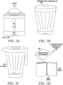
- the first receptacle 105 is configured to receive a first filter 108 (e.g. FIGS. 3D-3E ) comprising one of ground coffee, ground tea, or any particulate substance to brew the hot beverage (e.g. hot chocolate powder, ground espresso, etc.).
- the first receptacle 105 is a slot defined by the housing 101 and the system 100 includes a tray 110 (e.g grating on which the first filter is placed) which is sized based on one or more dimensions of the slot.
- the slot defined by the first receptacle 105 is sized based on the first filter 108 (e.g.
- FIGS. 3D-3E and the tray 110 is omitted such that the first filter 108 is configured and sized to be directly placed into the slot.
- the slot of the first receptacle 105 is positioned above the cavity 103 and the first filter 108 is made from biodegradable material and/or one or more seals along one or more edges of the first filter 108.
- the system 100 includes a hand-held impulse sealer as disclosed in U.S. Provisional Application Number 62/281,372 ( ⁇ 372 application) filed on 1 March 2019 and U.S. Application Number 16/803,847 ('847 application) filed on 27 February 2020 .
- a hand-held impulse sealer such as disclosed in the ⁇ 372 application and '847 application is used to form one or more seals 308 along the one or more edges of the first filter 108 (e.g. FIGS. 3D-3E ).
- the first filter 108 is placed on the tray 110 and the tray 110 is inserted in the first receptacle 105. In other embodiments, the first filter 108 is directly placed in the first receptacle 105 without the tray 110.
- the hand-held impulse sealer disclosed in the ⁇ 372 application and '847 application can be used to form a single first filter 108, such as by placing ground coffee or tea in a plastic enclosure and forming seals 308 along edges of the first filter 108.
- a cutting element of the hand-held impulse sealer can be used to cut the biodegradable material along or outside the seals 308, so to form a single filter 108 for use in the first receptacle 105.
- the hand-held impulse sealer can be used to simultaneously form multiple filters 108 at once, where the filters 108 are separated by adjacent seals 308, and the hand-held impulse sealer does not cut and separate the filter 108 until a desired time for use with the system 100 to brew coffee.
- the filters will be on a roll and pre-perforated.
- the filters are pre-sealed on multiple (e.g. 3) sides and open on a perforated edge for filling.
- the filters can be sealed with the hand-held impulse sealer after they are filled.
- the filters come in three sizes to fill (e.g. one for single cup, one for 4-6 cups and another for 10-12 cup). FIG.
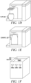
- FIG. 1G is an image that illustrates an example of a filter 108 formed from biodegradable material and used in the system 100 of FIG. 1A , according to an embodiment.
- the filter 108 is pre-sealed across the sides 152a, 152b, 152c.
- Contents 154 e.g. ground coffee, tea leaves, etc.
- the hand-held impulse sealer is used to seal the filter 108 across the fourth side (e.g. the side opposite the side 152c in FIG. 1G ).
- more than one seal along more than one edge of the filter 108 can be formed with the hand-held impulse sealer.
- the hand-held impulse sealer includes a plurality of spaced apart heating elements and a cutting element.
- the slot of the first receptacle 105 defines a rectangular or square cross-section and the edges or seals 308 of the first filter 108 define a rectangular or square shaped filter configured to fit in the rectangular or square cross-section of the slot of the first receptacle 105.
- the amount of ground coffee or tea placed in the first filter 108 and/or the size of the first filter 108 is adjusted so to filter a volume of water to fill the first container (e.g. cup 106) for a single serving of coffee.
- the system 100 includes a second receptacle 109 ( FIG. 1B ).
- the second receptacle 109 is covered by a top 116 of the housing 101.
- the second receptacle 109 is accessed by removing and/or rotating the top 116 of the housing 101 from a closed position ( FIG. 1A ) to an open position ( FIG. 1B ).
- the second receptacle 109 is configured to receive a second filter 118 ( FIG. 1B ) comprising ground coffee or tea or any ground material used to filter the hot beverage (e.g. hot chocolate powder).
- the second filter 118 is a reusable filter , such as a filter made from metal material and/or with openings that are sufficiently small so that ground coffee can be placed in the second filter 118 and water filters through the ground coffee without the ground coffee passing through the filter openings.
- the second filter 118 is similar to the first filter 108 but larger in dimension.
- the second receptacle 109 is accessed by removing the top 116 of the housing 101 and the second filter 118 is a reusable filter.
- the second receptacle 109 is positioned in a region of the housing 101 other than the top 116 (e.g. side region, back region, etc.).
- the second filter 118 is sized so that it is capable of filtering a second volume of coffee based on multiple servings of coffee and the second container 107 (e.g. carafe or coffee pot) is sized for the multiple servings of coffee.
- the system 100 also includes a rotor 130 ( FIG. 1F ) located at a third region (e.g. second side of the housing 101 opposite the first side where the first reservoir 102 is located) of the housing 101.
- the rotor 130 is configured to rotate about a rotational axis and is configured to rotatably engage an accessory container 132 (e.g. juicer 113 in FIG. 1A ) to rotate a rotary component (e.g. cone 112) of the accessory container 132 about the rotational axis.
- the rotor 130 causes the cone 112 of the juicer 113 to rotate so that a user can press a fruit (e.g.
- the accessory container 132 is a coffee grinder 120 ( FIG. 1B ) where the rotary component is a blade to grind coffee beans 121 positioned in the coffee grinder 120.
- the user places coffee beans 121 in the coffee grinder 120, activates the grinder 120 to grind the coffee beans 121 and subsequently places the ground coffee in one of the first filter 108 and/or second filter 118.
- the accessory container 132 is a pitcher 304 ( FIG. 3C ) with a rotating blade to blend ingredients placed inside the pitcher 304.
- the accessory container 132 is a frother 312 ( FIG.
- FIGS 3A-3B illustrate example embodiments of the juicer 113 and coffee grinder 120 previously discussed.
- the rotor 130 features a plurality of male grooves (e.g. six grooves) that are configured to be received in a plurality of corresponding slots at a base of the accessory container 132 (e.g. female slots) so that the accessory container 132 is rotatably engaged by the rotor 130.
- the system 100 includes one or more of the accessory containers listed above. In other embodiments, the system 100 includes all of the accessory containers discussed above.
- FIG. 5A is an image that illustrates an example of a bottom view of a base 502 of an accessory container 500 to be secured to a rotor of a system for brewing a hot beverage, according to an embodiment.
- FIG. 5B is an image that illustrates an example of a top perspective view of a rotary component 506 (e.g. wheel) within the accessory container 500 of FIG. 5A , according to an embodiment.
- FIG. 5C is an image that illustrates an example of a perspective view of a rotor 512 and torque base 510 of the system to secure the accessory container of FIG. 5A , according to an embodiment.
- FIG. 5D is an image that illustrates an example of a side view of the torque base 510 of FIG. 5C , according to an embodiment.
- the container 500 and torque base 510 are made from metallic and/or thermally conductive material.
- the torque base 510 can be used in place of the torque base of FIGS. 1A , 1F .
- the torque base 510 differs from the torque base of FIGS. 1A , 1F in the following respects.
- the torque base 510 includes a rotor 512 that matingly engages the opening 504 in the base 502 of the container 500 and is received in the cylinder 508 of the container 500.
- rotation of the rotor 512 causes the rotary component 506 (e.g. wheel) to rotate contents of the container 500.
- the torque base 510 includes a heating element 514 that contacts and/or provides heat to contents of the container 500 through the base 502 of the container 500 when the container 500 is placed in the torque base 510 ( FIG. 5D ).
- a panel is provided on a side of the torque base 510 with one or more settings to select one or more operating modes of the system.
- a first button 516a is for a cold mode that activates the rotor 512 without activating the heating element 514 so that the contents of the container 500 are spun (e.g. by the wheel) for a predetermined time (e.g. about 2 minutes or in a range from about 1 minute to about 3 minutes).
- a second button 516b is for a latte mode which activates the rotor 512 and the heating element 514 and causes the rotor 512 to spin for a predetermined time (e.g.
- the heating element 514 to rise in temperature and/or to cause an increase in the contents (e.g. milk, espresso, etc.) of the container 500 (e.g. to about 62,78°C-65,56°C (145F ⁇ 150F)).
- the volume of milk is about 177,44 ml ( 3 ⁇ 4 cup) or in a range from about 118,29 ml ( 1 ⁇ 2 cup) to about 473,18 ml (2 cups ) in the container 500.
- a third button 516c is for a cappuccino mode which activates the rotor 512 and the heating element 514 and causes the rotor 512 to spin for a predetermined time (e.g. about 120 seconds or in a range from about 80 seconds to about 160 seconds) and/or the heating element 514 to rise in temperature and/or to cause contents of the container 500 (e.g. milk, espresso, sugar, etc.) to rise in temperature (e.g. to about 62,78°C-65,56°C (145F ⁇ 150F)).
- the volume of milk is about 1 ⁇ 2 cup or in a range from about 59,14 ml to about 354,9 ml (from about 1 ⁇ 4 cup to about 1 1 ⁇ 2 cups).
- a further button (not shown) is provided to activate a soup mode that causes the rotor 512 to spin the contents of the container 500 (e.g. soup mix and/or soup ingredients) for a predetermined time (e.g. about 7 minutes) and/or to activate the heating element 514 to cause the temperature of the contents of the container 500 to rise to a threshold temperature (e.g. between about 87,78°C (190F) and about 104,44°C (220F)).
- a threshold temperature e.g. between about 87,78°C (190F) and about 104,44°C (220F).
- the soup mode is deactivated and the rotor 512 stops spinning the contents and/or the heating element 514 is deactivated after the temperature of the contents of the container 500 reach the threshold temperature.
- FIG. 2 is a block diagram that illustrates an example of the system 100 for preparing a heated beverage (e.g. filtering coffee, tea, etc.) of FIG. 1A , according to an embodiment.
- the housing 101 of the system 100 includes a controller 202 communicatively coupled to a power source 204.
- the system 100 also includes a heating reservoir 208 that receives water from the first water reservoir 102 and/or the second water reservoir 104, where the heating reservoir 208 maintains the water at a brewing temperature (e.g. boiling temperature of water or within a threshold temperature of the boiling temperature).
- a temperature sensor 209 is provided to measure a temperature of the water within the heating reservoir 208 and transmit data indicating the sensed temperature to the controller 202.
- a heating element 211 is also provided in the heating reservoir 208.
- the controller 202 determines (e.g. based on data from the temperature sensor 209) that the temperature of the water in the heating reservoir 208 is less than the brewing temperature, the controller 202 transmits a signal to the heating element 211 to increase the temperature of the water in the heating reservoir 208 to the brewing temperature.
- the user when a user wants the system 100 to brew coffee into the first container 106 via the first receptacle 105, the user first places the first filter 108 in the first receptacle 105.
- the user uses the hand-held impulse sealer of the ⁇ 372 application and the '847 application to form the first filter 108 using biodegradable material and ground coffee or other ground material (e.g. tea).
- the user then initiates the filtering process of the coffee into the first container 106.
- the user initiates the filtering process by pressing a first button 125a on a user panel.
- the user initiates the filtering by a different means (e.g.
- a signal to the controller 202 from a device that is in wireless communication with the system 100, such as an app on a smartphone).
- the user initiation of the filtering process causes a signal to be sent to the controller 202, which in turn transmits a signal to the power source 204 and the power source 204 causes a first pump 206A to pump hot water from the heating reservoir 208 to the first receptacle 105 with the first filter 108.
- the controller 202 causes the power source 204 to transmit electrical power to the first pump 206A for a duration so that a first volume of water (e.g.
- first receptacle 105 in a range from about 236,59 ml to about 887,21 ml (from about 8 oz to about 30 oz)
- first filter 108 into the first container 106 (e.g. Yeti ® container).
- a user wants the system 100 to brew coffee into the second container 107 via the second receptacle 109.
- the user first places ground coffee in the second filter 118 and places the second filter 118 in the second receptacle 109.
- the user places already ground coffee (e.g. not ground using the system 100) in the second filter 118 and places the second filter 118 in the second receptacle 109.
- the user places ground coffee in the metal reusable filter 118 and/or removes the first filter 108 from the first receptacle 105 (e.g. in the event that the first filter 108 is within the first receptacle 105).
- the user then initiates the filtering of the coffee into the second container 107.
- the user initiates the filtering process by pressing a second button 125b on a user panel.
- the user initiates the filtering by a different means (e.g. transmitting a signal to the controller 202 from a device that is in wireless communication with the system 100, such as an app on a smartphone).
- the user initiation of the filtering process causes a signal to be sent to the controller 202, which in turn transmits a signal to the power source 204 and the power source 204 causes a first pump 206A to pump hot water from the heating reservoir 208 to the second receptacle 109 with the second filter 118.
- the controller 202 causes the power source 204 to transmit electrical power to the first pump 206A for a duration so that a second volume of water (e.g. in a range from about 1,42 liters to about 2,84 liters (from about 6 cups to about 12 cups) cups)) is pumped to the second receptacle 109 and through the second filter 118 into the second container 107 (e.g. carafe).
- a second volume of water e.g. in a range from about 1,42 liters to about 2,84 liters (from about 6 cups to about 12 cups) cups
- the controller 202 transmits a signal to the power source 204 so that the power source 204 causes a second pump 206B to pump water from the first reservoir 102 and/or second reservoir 104 to the heating reservoir 208, to ensure that the heating reservoir 208 is at a threshold (e.g. full) level. In some embodiments, the controller 202 transmits this signal to the power source 204 after the first pump 206A pumps water from the heating reservoir 208 to the first receptacle 105 or second receptacle 109. In other embodiments, the controller 202 transmits this signal whenever the controller 202 determines that the level of water in the heating reservoir 208 is below a threshold level (e.g.
- the heating reservoir 208 has a level sensor 213 which transmits a signal to the controller 202 with data that indicates a level of water in the heating reservoir 208. Upon receiving this signal from the level sensor 213, the controller 202 compares the indicated level of water in the heating reservoir 208 with the threshold level (e.g. stored in a memory of the controller 202).
- the threshold level e.g. stored in a memory of the controller 202.
- the controller 202 determines that the level of water in the heating reservoir 208 is below the threshold level, the controller 202 subsequently sends the signal to the power source 204 in order to pump water to the heating reservoir 208 until the level of water in the heating reservoir 208 is back at the threshold level. Additionally, if the controller 202 determines that the level of water in the heating reservoir 208 is above the threshold level, the controller 202 does not send the signal to the power source 204.
- first reservoir 102 has a level sensor 111 that transmits data indicating a level of water in the first reservoir 102 to the controller 202.
- the controller 202 compares the level of water in the first reservoir 102 with a low threshold level of water in the reservoir 102 (e.g. stored in a memory of the controller 202).
- the low threshold level is about 20% or in a range from about 10% to about 50% and/or in a range from about 1% to about 70%).
- the controller 202 determines that the level of water in the first reservoir 102 (e.g.
- the controller 202 transmits a signal to the power source 204 to cause the second pump 206B to pump water from the second reservoir 104 to the first reservoir 102 until the level of water in the first reservoir 102 is at or above the low threshold level.
- the second reservoir 104 is provided as a backup reservoir to the first reservoir 102.
- the rotor 130 is electrically coupled to the same power source 204 within the housing 101 as the first and second pumps 206A, 206B.
- the rotor 512 of FIG. 5C is connected to the system in a similar manner as the rotor 130 depicted in FIG. 2 .
- the power source 204 is sufficient to simultaneously power the rotor 130 and the pumps 206A, 206B.
- the power source 204 can power either the rotor 130 or the pumps 206A, 206B and thus when the power source 204 is powering one of the rotor and pumps, the other of the rotor and pumps is not used (e.g.
- the controller 202 is programmed such that multiple signals are not transmitted to the power source 204 to simultaneously power the rotor and pump(s)).
- a plurality of buttons 126 are provided on the user panel.
- the user presses a first button 126a ( FIG. 1F ) to cause the controller 202 to transmit a signal to the power source 204 which causes the rotor 130 to rotate at a first rotational speed.
- the user presses a second button 126b ( FIG. 1F ) to cause the controller 202 to transmit a signal to the power source 204 which causes the rotor 130 to rotate at a second rotational speed different from the first rotational speed.
- the user presses a third button 126c ( FIG.
- buttons 126a, 126b, 126b can press one of the three buttons 126a, 126b, 126b, based on the particular accessory container that is being used on the rotor 130 and/or based on the particular ingredients being chopped/cut/ground/etc within the accessory container.
- FIG. 1B depicts three buttons 126a through 126c on the user panel, the system is not limited to this particular button arrangement and can include less or more than three buttons (e.g. less or more than three rotational speeds).
- the first rotational speed, the second rotational speed and the third rotational speeds have respective values that are sufficient to process the different contents of the container as desired by the user (e.g. grind the coffee beans, juice the fruit applied to the juicer 113, froth the foam using the frother 312, etc) which are appreciated by one of ordinary skill in the art.
- FIG. 4 a flowchart is depicted that provides a method 400 for operating the system 100.
- the flowchart of FIG. 4 depicts particular steps in a particular order, in some embodiments the steps may be arranged in a different order and/or one or more steps may be omitted and/or additional steps may be included as long as the resulting embodiment is encompassed by the appended claims.
- step 401 involves the user placing the first container 106 or second container 107 in the cavity 103 of the housing 101.
- the user places the first container 106 or second container 107 in the cavity 103, based on whether the user wants to have a single serving or multiple serving of hot beverage (e.g. coffee, tea, etc.) brewed by the system 100.
- the user places the first filter 108 in the first receptacle 105 or the second filter 118 in the second receptacle 109 (after filling the filter with ground coffee).
- the user uses the hand-held impulse sealer of the ⁇ 372 application and the '847 application in step 401 to make the first filter 108 or second filter 118 by first placing ground coffee in an enclosure formed by biodegradable material and applying the hand-held impulse sealer along the edges of the biodegradable material to form the seals 308 along the edges of the filter.
- the first filter 108 and/or second filter 118 can be formed by the hand-held impulse sealer using material other than biodegradable material (e.g. plastic material).
- the user applies the hand-held impulse sealer to the biodegradable material so that the seals 308 are formed along the filter in accordance with one or more dimensions of the first receptacle 105 (e.g. for the first filter 108) or the second receptacle 109 (e.g. for the second filter 118).
- the user in step 401 uses the hand-held impulse sealer to form seals 308 along the first filter 108 based on the dimensions of the slot so that the first filter 108 is a square or rectangular shaped filter in accordance with the square or rectangular shaped slot.
- first filter 108 has dimensions of about 6.35cm (2.5 inches) long by about 6.35cm (2.5 inches) wide (e.g. small size filter 108) and/or about 12.70cm (5 inches) long by about 12.70cm (5 inches) long (e.g. large size filter 118).
- the slot of the first receptacle 105 has dimensions of about 7.62cm (3 inches) wide and about 10.16cm - 12.70cm (4-5 inches) long and/or a height of about 1.9cm (3 ⁇ 4 inch).
- a base of the first receptacle 105 features the tray 110 (e.g. grate) to allow water to flow through to a a funnel-type apparatus (e.g.
- FIG. 1G is an image that illustrates an example of the filter 108 formed from biodegradable material and used in the system 100 of FIG. 1A , according to an embodiment.
- the cutting element of the hand-held impulse sealer in the ⁇ 372 application and '847 application is used to cut the biodegradable material along the seals 308 so to form the first filter 108 and/or separate the first filter 108 from remaining bulk amount of biodegradable material.
- the biodegradable material discussed herein involves biodegradable material with openings sufficient for hot water to filter through the material for purposes of filtering the ground coffee within the first filter 108.
- step 402 the user presses one of the buttons 125a, 125b based on whether the user wants the system 100 to brew coffee to the first container 106 or second container 107.
- the user initiates the filtering process using a device in wireless communication with the controller 202 and system 100 (e.g. with an app on a smartphone) which transmits a signal to the controller 202 to indicate whether the user wants coffee to be brewed in the first container 106 or the second container 107.
- step 404 the controller 202 and power source 204 causes the first pump 206A to pump water from the heating reservoir 208 through the first filter 108 in the first receptacle 105 or the second filter 118 in the second receptacle 109, depending on which button 125a, 125b was pressed (or based on the signal received by the controller 202 from the device in wireless communication with the controller 202) in step 402.
- step 406 the water pumped in step 404 from the heating reservoir 208 to the first receptacle 105 is filtered by the ground coffee in the first filter 108 or the water pumped from the heating reservoir 208 to the second receptacle 109 is filtered by the ground coffee in the second filter 118.
- step 408 the filtered water in step 406 fills either the first container 106 or the second container 107, depending on which button was pressed in step 402.
- an accessory container e.g. juicer 113, coffee grinder 120, pitcher 304, etc.
- a plurality of slots in a base of the accessory container engage a plurality of grooves of the rotor 130.
- the accessory container is positioned on the rotor so that the grooves of the rotor securely engage the slots in the base of the accessory container, so that the rotor 130 can effectively rotate a rotary component of the accessory container.
- step 412 the user presses one or more buttons 126a, 126b, 126c to activate the rotor 130 at a selective rotation speed, in order to use the accessory container for a number of purposes (e.g. use the grinder 120 to grind coffee beans 121 to be used in the filters 108, 118; use the juicer 113 to press fruit onto the rotating cone 112 to draw juice into the juicer 113, etc. ).
- steps 410 and 412 can be performed prior to steps 402-408 and/or can be performed without performing steps 402-408 such that the rotor 130 can be used independent of the brewing features of the system 100.
Landscapes
- Engineering & Computer Science (AREA)
- Food Science & Technology (AREA)
- Mechanical Engineering (AREA)
- Life Sciences & Earth Sciences (AREA)
- Chemical & Material Sciences (AREA)
- Polymers & Plastics (AREA)
- Apparatus For Making Beverages (AREA)
Claims (14)
- Système (100), comprenant :un boîtier (101) ;un premier réservoir d'eau (102) situé dans une première zone du boîtier (101) ;un deuxième réservoir d'eau (104) situé dans une deuxième zone du boîtier (101) ;un réservoir de chauffage (208) en communication fluide avec le premier et le second réservoir d'eau (102, 104) pour recevoir l'eau d'au moins un des premiers réservoirs d'eau (102) et du second réservoir d'eau (104), dans lequel le réservoir de chauffage (208) est configuré pour maintenir l'eau à une température d'infusion ;un premier réceptacle (105) en communication fluide avec le réservoir de chauffage (208),ledit premier réceptacle (105) étant défini par le boîtier (101), ledit premier réceptacle (105) étant configuré pour recevoir un premier filtre (108) comprenant du café moulu ;un second réceptacle (109) en communication fluide avec le réservoir de chauffage (208), ledit second réceptacle (109) étant défini par le boîtier (101), ledit second réceptacle (109) étant configuré pour recevoir un second filtre (118) comprenant du café moulu ; etune cavité (103) en communication fluide avec le premier et le second réceptacle (105, 109), ladite cavité (103) étant définie par le boîtier (101) pour positionner un premier conteneur (106) et un second conteneur (107) ;dans lequel le système (100) est configuré pour infuser un premier volume de café pour remplir le premier conteneur (106) en fonction du placement du premier filtre (108) dans le premier conteneur (105) et du premier volume d'eau pompé depuis le réservoir de chauffage (208) à travers le premier filtre (108) ; etle système (100) est configuré pour infuser un deuxième volume de café pour remplir le deuxième conteneur (107) en fonction du placement du deuxième filtre (118) dans le deuxième conteneur (109) et du deuxième volume d'eau pompé du réservoir de chauffage (208) à travers le deuxième filtre (118) ;dans lequel le système comprendun capteur de niveau (111) configuré pour mesurer un niveau d'eau dans le premier réservoir (102) ;un contrôleur (202) couplé de manière communicative au capteur de niveau (111) pour recevoir les premières données indiquant le niveau de l'eau dans le premier réservoir (102), pour comparer les premières données avec les secondes données indiquant un seuil de bas niveau de l'eau dans le premier réservoir (102) et pour transmettre un signal basé sur la comparaison des premières données et des secondes données ; etune pompe (206B) couplée de manière communicative au contrôleur (202), dans laquelle la pompe (206B) est configurée pour pomper l'eau du second réservoir (104) vers le premier réservoir (102) en fonction de la réception du signal du contrôleur (202).
- Système (100) de la revendication 1, comprenant en outre un rotor (130) situé dans une troisième région du boîtier (101), ledit rotor (130) configuré pour tourner autour d'un axe de rotation et dans lequel le rotor (130) est configuré pour engager de manière rotative un conteneur d'accessoires (132) afin de faire tourner un composant rotatif (112) du conteneur d'accessoires (132) autour de l'axe de rotation.
- Système (100) selon la revendication 2, comprenant en outre :une source d'énergie (204) ;une première pompe (206A) configurée pour pomper l'eau du réservoir de chauffage (208) vers au moins l'un du premier réceptacle (105) et du second réceptacle (109), la première pompe (206A) étant couplée électriquement à la source d'énergie (204) pour recevoir l'énergie électrique nécessaire au pompage de l'eau ;et dans lequel le rotor (130) est couplé électriquement à la source d'énergie (204) pour recevoir de l'énergie électrique et tourner autour de l'axe de rotation.
- Système (100) de la revendication 3, dans lequel la source d'énergie (204) est positionnée à l'intérieur du boîtier (101) et dans lequel le rotor (130) comprend une pluralité de rainures configurées pour s'adapter à une pluralité de fentes adjacentes à une base du conteneur d'accessoires (132), et dans lequel le système (100) comprend en outre le conteneur d'accessoires (132), dans lequel le conteneur d'accessoires (132) comprend au moins l'un parmi un mixeur, un presse-agrumes (113), un robot ménager et un moulin à café (120) ; et
le système (100) comprend en outre au moins l'un des éléments suivants : le mixeur, le presse-agrumes (113), le robot ménager et le moulin à café (120). - Système (100) de la revendication 1, dans lequel au moins l'un des éléments suivants est présent :la première région est un côté du boîtier (101) et la seconde région est un arrière du boîtier (101) et dans laquelle la cavité (103) est définie par un avant du boîtier (101) opposé à l'arrière du boîtier ; etle premier réceptacle (105) est une fente définie par le boîtier (101) positionné au-dessus de la cavité (103) et dans lequel le premier filtre (108) comprend un matériau biodégradable et un ou plusieurs joints d'étanchéité le long d'un ou plusieurs bords du premier filtre (108).
- Système (100) de la revendication 2, dans lequel la première région est un premier côté du boîtier (101), la deuxième région est un arrière du boîtier (101), la troisième région est un deuxième côté du boîtier (101) opposé à la première région et dans lequel la cavité (103) est définie par un avant du boîtier (101) opposé à l'arrière du boîtier (101).
- Système (100) de la revendication 5, comprenant en outre une soudeuse à impulsion manuelle configurée pour former un ou plusieurs joints le long d'un ou plusieurs bords du premier filtre (108).
- Système (100) de la revendication 5, dans lequel le premier filtre (108) est dimensionné de manière à ce que le premier volume de café soit une portion unique de café et que le premier conteneur (106) soit une tasse unique dimensionnée pour la portion unique de café.
- Système (100) de la revendication 1, dans lequel on accède au deuxième réceptacle (109) en retirant la partie supérieure du boîtier (101) et dans lequel le deuxième filtre (118) est un filtre réutilisable.
- Système (100) de la revendication 9, dans lequel le filtre réutilisable est fabriqué à partir d'un matériau métallique et dans lequel le second filtre (118) est dimensionné de manière à ce que le second volume de café soit constitué de plusieurs portions de café et que le second conteneur (107) soit une casserole dimensionnée pour les multiples portions de café.
- Système (100) selon la revendication 3, comprenant en outre :une interface utilisateur comprenant plusieurs boutons (125, 126) ; etun contrôleur (202) couplé de manière communicative à la source d'énergie (204) et à chacun des boutons (125, 126) ;dans lequel le contrôleur (202) est configuré pour transmettre un premier signal à la source d'énergie (204) afin que la première pompe (206A) pompe l'eau du réservoir de chauffage (208) vers le premier conteneur (105) lorsqu'un premier bouton (125a) de la pluralité de boutons (125, 126) est appuyé ;et dans lequel le contrôleur (202) est configuré pour transmettre un second signal à la source d'énergie (204) afin que la première pompe (206A) pompe l'eau du réservoir de chauffage (208) vers le second réceptacle (109) lorsqu'un second bouton (125b) de la pluralité de boutons (125, 126) est appuyé.
- Système (100) de la revendication 11, dans lequel au moins l'un des éléments suivants est présent :la pluralité de boutons (125, 126) comprend en outre un ou plusieurs boutons secondaires (126a, 126b, 126c) qui indiquent une ou plusieurs vitesses de rotation du rotor (130) et dans lequel le contrôleur (202) est configuré pour transmettre un premier signal de vitesse à la source d'énergie (204) afin de faire tourner le rotor (130) à une première vitesse lorsqu'un bouton secondaire (126a) indiquant la première vitesse est appuyé et dans lequel le contrôleur (202) est également configuré pour transmettre un second signal de vitesse à la source d'énergie (204) afin de faire tourner le rotor (130) à une seconde vitesse différente de la première vitesse lorsqu'un bouton secondaire (126b) indiquant la seconde vitesse est appuyé ; etle système comprend en outre une deuxième pompe (206B) couplée de manière communicative à la source d'énergie (204) et au contrôleur (202), cette deuxième pompe (206B) étant configurée pour pomper l'eau du premier réservoir (102) vers le réservoir de chauffage (208) lorsque le premier bouton (125a) de la pluralité de boutons (125, 126) est appuyé et étant en outre configurée pour pomper l'eau du deuxième réservoir (104) vers le réservoir de chauffage (208) lorsque le deuxième bouton (125b) de la pluralité de boutons (125a, 125b) est appuyé.
- Procédé (400) d'utilisation du système (100) de la revendication 3, comprenant :placer (401) l'un du premier conteneur (106) et du second conteneur (107) dans la cavité (103) ,appuyer (402), sur une interface utilisateur, sur l'un des boutons (125, 126) ;pomper (404), avec la première pompe (206A), de l'eau du réservoir de chauffage (208) vers l'un du premier filtre (108) et du second filtre (118), sur la base de l'étape de pression (402), dans laquelle le fait d'appuyer sur un premier bouton (125a) de la pluralité de boutons (125, 126) amène un contrôleur (202) couplé de manière communicative à l'interface utilisateur à transmettre un premier signal à la source d'énergie (204) pour provoquer le pompage du premier volume d'eau du réservoir de chauffage (208) vers le premier filtre (108) et dans lequel l'appui sur un second bouton (125b) de la pluralité de boutons (125, 126) amène le contrôleur (202) à transmettre un second signal à la source d'énergie (204) pour provoquer le pompage du second volume d'eau du réservoir de chauffage (208) à travers le second filtre (118) ;filtrer (406) l'eau du réservoir de chauffage (208) avec l'un du premier filtre (108) et du second filtre (118) en fonction de l'étape de pompage (404) ; etremplir (408) le premier conteneur (106) et le second conteneur (107) dans la cavité (103) sur la base de l'étape de filtrage (406).
- Procédé (400) de la revendication 13, dans laquelle la pluralité de boutons (125, 126) comprend en outre un ou plusieurs boutons secondaires (126a, 126b, 126c) qui indiquent une ou plusieurs vitesses de rotation du rotor (130) et dans lequel le contrôleur (202) est configuré pour transmettre un premier signal de vitesse à la source d'énergie (204) pour faire tourner le rotor (130) à une première vitesse lorsqu'on appuie sur un bouton secondaire (126a) qui indique la première vitesse et dans lequel le contrôleur (202) est également configuré pour transmettre un second signal de vitesse à la source d'énergie (204) pour faire tourner le rotor (130) à une seconde vitesse différente de la première vitesse lorsqu'on appuie sur un bouton secondaire (126b) qui indique la seconde vitesse.
Applications Claiming Priority (2)
| Application Number | Priority Date | Filing Date | Title |
|---|---|---|---|
| US201962878787P | 2019-07-26 | 2019-07-26 | |
| PCT/US2020/043723 WO2021021726A1 (fr) | 2019-07-26 | 2020-07-27 | Système et procédé de filtrage de boisson chaude |
Publications (3)
| Publication Number | Publication Date |
|---|---|
| EP4003107A1 EP4003107A1 (fr) | 2022-06-01 |
| EP4003107A4 EP4003107A4 (fr) | 2023-08-23 |
| EP4003107B1 true EP4003107B1 (fr) | 2025-01-29 |
Family
ID=74229556
Family Applications (1)
| Application Number | Title | Priority Date | Filing Date |
|---|---|---|---|
| EP20847387.6A Active EP4003107B1 (fr) | 2019-07-26 | 2020-07-27 | Système et procédé de filtrage de boisson chaude |
Country Status (6)
| Country | Link |
|---|---|
| US (2) | US12419456B2 (fr) |
| EP (1) | EP4003107B1 (fr) |
| JP (1) | JP7555393B2 (fr) |
| KR (1) | KR20220035923A (fr) |
| CN (1) | CN114173620A (fr) |
| WO (1) | WO2021021726A1 (fr) |
Family Cites Families (25)
| Publication number | Priority date | Publication date | Assignee | Title |
|---|---|---|---|---|
| GB932979A (en) * | 1960-01-08 | 1963-07-31 | George Regan Bunn | Beverage making machine |
| US4757754A (en) * | 1987-01-20 | 1988-07-19 | Welker William C | Coffee maker |
| US5855163A (en) * | 1996-12-10 | 1999-01-05 | Demars; Robert A. | Coffee brewer |
| US5829340A (en) * | 1997-04-15 | 1998-11-03 | Yang; Po-Han | Coffee maker |
| US6729226B2 (en) * | 2002-04-24 | 2004-05-04 | Joseph Mangiapane | Multiple beverage preparation device |
| CN2574554Y (zh) * | 2002-10-09 | 2003-09-24 | 关耀干 | 冷热双料饮料机 |
| US7021197B2 (en) | 2003-07-18 | 2006-04-04 | Electrical & Electronics Ltd. | Hot beverage machine |
| JP4133754B2 (ja) * | 2003-11-13 | 2008-08-13 | 株式会社泉精器製作所 | コーヒーメーカー |
| US7104184B2 (en) * | 2004-01-13 | 2006-09-12 | Eytan Biderman | Feeding formula appliance |
| US7089849B2 (en) * | 2004-05-06 | 2006-08-15 | Electrical And Electronics Limited | Single/multiple beverage machine |
| MX2007002621A (es) * | 2004-09-03 | 2007-05-07 | Everest International Ltd | Metodo y aparato para producir agua. |
| JP4781053B2 (ja) * | 2005-09-02 | 2011-09-28 | 株式会社ジャムコ | 航空機に装備されるコーヒーメーカーに対して温水を供給する給湯装置 |
| US7565860B1 (en) * | 2005-11-21 | 2009-07-28 | Liu Donald C | Multi-functional hot beverage brewing device |
| JP2011161223A (ja) | 2010-01-15 | 2011-08-25 | Suntory Holdings Ltd | コーヒー抽出装置 |
| KR101934122B1 (ko) | 2010-02-17 | 2019-04-05 | 코닌클리케 도우베 에그베르츠 비.브이. | 커피 음료 시스템, 커피 우려냄 장치, 커피콩 패키징 카트리지 및 커피 음료를 제조하기 위한 방법 |
| WO2013097999A1 (fr) * | 2011-12-26 | 2013-07-04 | Arcelik Anonim Sirketi | Machine de préparation de boissons chaudes |
| CN103806013A (zh) * | 2013-06-19 | 2014-05-21 | 林信涌 | 气水循环系统 |
| DE202013105700U1 (de) * | 2013-12-16 | 2014-01-10 | Onno Jetel E.K. | Behälter für eine Einmalportion einer Substanz zur Zubereitung eines Heißgetränks |
| CN105395072B (zh) | 2015-04-28 | 2018-10-19 | 周林斌 | 一种磨豆咖啡壶的密封上盖 |
| CN107149407B (zh) * | 2016-03-04 | 2019-10-11 | 威斯达电器(中山)制造有限公司 | 咖啡机及其控制方法 |
| CN206431107U (zh) * | 2016-12-06 | 2017-08-22 | 重庆交通大学 | 用于模拟隧道排水管碳酸钙结晶情况的装置 |
| IT201700083634A1 (it) * | 2017-07-21 | 2019-01-21 | Nuova Simonelli S P A | Macchina da caffe' autopulente. |
| CN107242810A (zh) * | 2017-08-02 | 2017-10-13 | 无锡智汇空间投资管理有限公司 | 一种简单实用的研磨型家用豆浆机 |
| CN107928413A (zh) * | 2017-12-09 | 2018-04-20 | 海宁三易科技有限公司 | 一种防重烧饮水机 |
| CN107981731A (zh) * | 2017-12-26 | 2018-05-04 | 黄斌 | 一种饮水机及其控制方法 |
-
2020
- 2020-07-27 EP EP20847387.6A patent/EP4003107B1/fr active Active
- 2020-07-27 CN CN202080054190.9A patent/CN114173620A/zh active Pending
- 2020-07-27 KR KR1020227004379A patent/KR20220035923A/ko active Pending
- 2020-07-27 JP JP2022505399A patent/JP7555393B2/ja active Active
- 2020-07-27 US US17/629,850 patent/US12419456B2/en active Active
- 2020-07-27 WO PCT/US2020/043723 patent/WO2021021726A1/fr not_active Ceased
-
2025
- 2025-09-05 US US19/320,717 patent/US20260000236A1/en active Pending
Also Published As
| Publication number | Publication date |
|---|---|
| US12419456B2 (en) | 2025-09-23 |
| EP4003107A1 (fr) | 2022-06-01 |
| JP7555393B2 (ja) | 2024-09-24 |
| CN114173620A (zh) | 2022-03-11 |
| JP2022552583A (ja) | 2022-12-19 |
| US20220272998A1 (en) | 2022-09-01 |
| US20260000236A1 (en) | 2026-01-01 |
| EP4003107A4 (fr) | 2023-08-23 |
| KR20220035923A (ko) | 2022-03-22 |
| WO2021021726A1 (fr) | 2021-02-04 |
Similar Documents
| Publication | Publication Date | Title |
|---|---|---|
| KR101469723B1 (ko) | 사전 포장된 일회용 용기 | |
| US6725763B2 (en) | Device and method for making coffee and espresso drinks | |
| CA2544686A1 (fr) | Brasseur a volume reglable | |
| US20220007876A1 (en) | Beverage Brewing System | |
| US5800852A (en) | Method for making a coffee/tea/beverage using a table-blender and a microwave-oven | |
| EP3449779B1 (fr) | Dispositif de préparation de boissons | |
| US20140287116A1 (en) | Single-serve container brewer and coffeemaker | |
| EP4003107B1 (fr) | Système et procédé de filtrage de boisson chaude | |
| HK40063204A (en) | System and method for filtering a hot beverage | |
| AU2006251453A1 (en) | Kit for and method of preparing a coffee beverage | |
| RU2805680C2 (ru) | Кофемашина | |
| WO2004045349A1 (fr) | Dispositif et procédé de confection de cafés et d'expressos | |
| HK1187504A (en) | Brewed beverage appliance and method |
Legal Events
| Date | Code | Title | Description |
|---|---|---|---|
| STAA | Information on the status of an ep patent application or granted ep patent |
Free format text: STATUS: THE INTERNATIONAL PUBLICATION HAS BEEN MADE |
|
| PUAI | Public reference made under article 153(3) epc to a published international application that has entered the european phase |
Free format text: ORIGINAL CODE: 0009012 |
|
| STAA | Information on the status of an ep patent application or granted ep patent |
Free format text: STATUS: REQUEST FOR EXAMINATION WAS MADE |
|
| 17P | Request for examination filed |
Effective date: 20220224 |
|
| AK | Designated contracting states |
Kind code of ref document: A1 Designated state(s): AL AT BE BG CH CY CZ DE DK EE ES FI FR GB GR HR HU IE IS IT LI LT LU LV MC MK MT NL NO PL PT RO RS SE SI SK SM TR |
|
| DAV | Request for validation of the european patent (deleted) | ||
| DAX | Request for extension of the european patent (deleted) | ||
| A4 | Supplementary search report drawn up and despatched |
Effective date: 20230724 |
|
| RIC1 | Information provided on ipc code assigned before grant |
Ipc: A47J 31/46 20060101ALI20230718BHEP Ipc: A47J 31/40 20060101ALI20230718BHEP Ipc: A47J 31/24 20060101ALI20230718BHEP Ipc: A47J 31/00 20060101ALI20230718BHEP Ipc: A23F 5/26 20060101ALI20230718BHEP Ipc: A47J 31/44 20060101AFI20230718BHEP |
|
| GRAP | Despatch of communication of intention to grant a patent |
Free format text: ORIGINAL CODE: EPIDOSNIGR1 |
|
| STAA | Information on the status of an ep patent application or granted ep patent |
Free format text: STATUS: GRANT OF PATENT IS INTENDED |
|
| INTG | Intention to grant announced |
Effective date: 20240820 |
|
| GRAS | Grant fee paid |
Free format text: ORIGINAL CODE: EPIDOSNIGR3 |
|
| GRAA | (expected) grant |
Free format text: ORIGINAL CODE: 0009210 |
|
| STAA | Information on the status of an ep patent application or granted ep patent |
Free format text: STATUS: THE PATENT HAS BEEN GRANTED |
|
| AK | Designated contracting states |
Kind code of ref document: B1 Designated state(s): AL AT BE BG CH CY CZ DE DK EE ES FI FR GB GR HR HU IE IS IT LI LT LU LV MC MK MT NL NO PL PT RO RS SE SI SK SM TR |
|
| REG | Reference to a national code |
Ref country code: GB Ref legal event code: FG4D |
|
| REG | Reference to a national code |
Ref country code: CH Ref legal event code: EP |
|
| REG | Reference to a national code |
Ref country code: DE Ref legal event code: R096 Ref document number: 602020045615 Country of ref document: DE |
|
| REG | Reference to a national code |
Ref country code: IE Ref legal event code: FG4D |
|
| REG | Reference to a national code |
Ref country code: NL Ref legal event code: MP Effective date: 20250129 |
|
| PG25 | Lapsed in a contracting state [announced via postgrant information from national office to epo] |
Ref country code: NL Free format text: LAPSE BECAUSE OF FAILURE TO SUBMIT A TRANSLATION OF THE DESCRIPTION OR TO PAY THE FEE WITHIN THE PRESCRIBED TIME-LIMIT Effective date: 20250129 |
|
| PG25 | Lapsed in a contracting state [announced via postgrant information from national office to epo] |
Ref country code: RS Free format text: LAPSE BECAUSE OF FAILURE TO SUBMIT A TRANSLATION OF THE DESCRIPTION OR TO PAY THE FEE WITHIN THE PRESCRIBED TIME-LIMIT Effective date: 20250429 |
|
| PG25 | Lapsed in a contracting state [announced via postgrant information from national office to epo] |
Ref country code: FI Free format text: LAPSE BECAUSE OF FAILURE TO SUBMIT A TRANSLATION OF THE DESCRIPTION OR TO PAY THE FEE WITHIN THE PRESCRIBED TIME-LIMIT Effective date: 20250129 |
|
| PG25 | Lapsed in a contracting state [announced via postgrant information from national office to epo] |
Ref country code: PL Free format text: LAPSE BECAUSE OF FAILURE TO SUBMIT A TRANSLATION OF THE DESCRIPTION OR TO PAY THE FEE WITHIN THE PRESCRIBED TIME-LIMIT Effective date: 20250129 |
|
| PG25 | Lapsed in a contracting state [announced via postgrant information from national office to epo] |
Ref country code: ES Free format text: LAPSE BECAUSE OF FAILURE TO SUBMIT A TRANSLATION OF THE DESCRIPTION OR TO PAY THE FEE WITHIN THE PRESCRIBED TIME-LIMIT Effective date: 20250129 |
|
| REG | Reference to a national code |
Ref country code: LT Ref legal event code: MG9D |
|
| PG25 | Lapsed in a contracting state [announced via postgrant information from national office to epo] |
Ref country code: IS Free format text: LAPSE BECAUSE OF FAILURE TO SUBMIT A TRANSLATION OF THE DESCRIPTION OR TO PAY THE FEE WITHIN THE PRESCRIBED TIME-LIMIT Effective date: 20250529 Ref country code: NO Free format text: LAPSE BECAUSE OF FAILURE TO SUBMIT A TRANSLATION OF THE DESCRIPTION OR TO PAY THE FEE WITHIN THE PRESCRIBED TIME-LIMIT Effective date: 20250429 |
|
| REG | Reference to a national code |
Ref country code: AT Ref legal event code: MK05 Ref document number: 1762563 Country of ref document: AT Kind code of ref document: T Effective date: 20250129 |
|
| PG25 | Lapsed in a contracting state [announced via postgrant information from national office to epo] |
Ref country code: HR Free format text: LAPSE BECAUSE OF FAILURE TO SUBMIT A TRANSLATION OF THE DESCRIPTION OR TO PAY THE FEE WITHIN THE PRESCRIBED TIME-LIMIT Effective date: 20250129 |
|
| PG25 | Lapsed in a contracting state [announced via postgrant information from national office to epo] |
Ref country code: LV Free format text: LAPSE BECAUSE OF FAILURE TO SUBMIT A TRANSLATION OF THE DESCRIPTION OR TO PAY THE FEE WITHIN THE PRESCRIBED TIME-LIMIT Effective date: 20250129 Ref country code: PT Free format text: LAPSE BECAUSE OF FAILURE TO SUBMIT A TRANSLATION OF THE DESCRIPTION OR TO PAY THE FEE WITHIN THE PRESCRIBED TIME-LIMIT Effective date: 20250529 |
|
| PG25 | Lapsed in a contracting state [announced via postgrant information from national office to epo] |
Ref country code: GR Free format text: LAPSE BECAUSE OF FAILURE TO SUBMIT A TRANSLATION OF THE DESCRIPTION OR TO PAY THE FEE WITHIN THE PRESCRIBED TIME-LIMIT Effective date: 20250430 Ref country code: BG Free format text: LAPSE BECAUSE OF FAILURE TO SUBMIT A TRANSLATION OF THE DESCRIPTION OR TO PAY THE FEE WITHIN THE PRESCRIBED TIME-LIMIT Effective date: 20250129 |
|
| PG25 | Lapsed in a contracting state [announced via postgrant information from national office to epo] |
Ref country code: AT Free format text: LAPSE BECAUSE OF FAILURE TO SUBMIT A TRANSLATION OF THE DESCRIPTION OR TO PAY THE FEE WITHIN THE PRESCRIBED TIME-LIMIT Effective date: 20250129 |
|
| PG25 | Lapsed in a contracting state [announced via postgrant information from national office to epo] |
Ref country code: SE Free format text: LAPSE BECAUSE OF FAILURE TO SUBMIT A TRANSLATION OF THE DESCRIPTION OR TO PAY THE FEE WITHIN THE PRESCRIBED TIME-LIMIT Effective date: 20250129 |
|
| PG25 | Lapsed in a contracting state [announced via postgrant information from national office to epo] |
Ref country code: SM Free format text: LAPSE BECAUSE OF FAILURE TO SUBMIT A TRANSLATION OF THE DESCRIPTION OR TO PAY THE FEE WITHIN THE PRESCRIBED TIME-LIMIT Effective date: 20250129 |
|
| PG25 | Lapsed in a contracting state [announced via postgrant information from national office to epo] |
Ref country code: DK Free format text: LAPSE BECAUSE OF FAILURE TO SUBMIT A TRANSLATION OF THE DESCRIPTION OR TO PAY THE FEE WITHIN THE PRESCRIBED TIME-LIMIT Effective date: 20250129 |
|
| PGFP | Annual fee paid to national office [announced via postgrant information from national office to epo] |
Ref country code: DE Payment date: 20250725 Year of fee payment: 6 |
|
| PGFP | Annual fee paid to national office [announced via postgrant information from national office to epo] |
Ref country code: IT Payment date: 20250728 Year of fee payment: 6 |
|
| PG25 | Lapsed in a contracting state [announced via postgrant information from national office to epo] |
Ref country code: CZ Free format text: LAPSE BECAUSE OF FAILURE TO SUBMIT A TRANSLATION OF THE DESCRIPTION OR TO PAY THE FEE WITHIN THE PRESCRIBED TIME-LIMIT Effective date: 20250129 Ref country code: EE Free format text: LAPSE BECAUSE OF FAILURE TO SUBMIT A TRANSLATION OF THE DESCRIPTION OR TO PAY THE FEE WITHIN THE PRESCRIBED TIME-LIMIT Effective date: 20250129 |
|
| PG25 | Lapsed in a contracting state [announced via postgrant information from national office to epo] |
Ref country code: RO Free format text: LAPSE BECAUSE OF FAILURE TO SUBMIT A TRANSLATION OF THE DESCRIPTION OR TO PAY THE FEE WITHIN THE PRESCRIBED TIME-LIMIT Effective date: 20250129 |
|
| PG25 | Lapsed in a contracting state [announced via postgrant information from national office to epo] |
Ref country code: SK Free format text: LAPSE BECAUSE OF FAILURE TO SUBMIT A TRANSLATION OF THE DESCRIPTION OR TO PAY THE FEE WITHIN THE PRESCRIBED TIME-LIMIT Effective date: 20250129 |
|
| REG | Reference to a national code |
Ref country code: DE Ref legal event code: R097 Ref document number: 602020045615 Country of ref document: DE |
|
| PLBE | No opposition filed within time limit |
Free format text: ORIGINAL CODE: 0009261 |
|
| STAA | Information on the status of an ep patent application or granted ep patent |
Free format text: STATUS: NO OPPOSITION FILED WITHIN TIME LIMIT |
|
| REG | Reference to a national code |
Ref country code: CH Ref legal event code: L10 Free format text: ST27 STATUS EVENT CODE: U-0-0-L10-L00 (AS PROVIDED BY THE NATIONAL OFFICE) Effective date: 20251210 |
|
| 26N | No opposition filed |
Effective date: 20251030 |
|
| REG | Reference to a national code |
Ref country code: CH Ref legal event code: H13 Free format text: ST27 STATUS EVENT CODE: U-0-0-H10-H13 (AS PROVIDED BY THE NATIONAL OFFICE) Effective date: 20260224 |
|
| PG25 | Lapsed in a contracting state [announced via postgrant information from national office to epo] |
Ref country code: LU Free format text: LAPSE BECAUSE OF NON-PAYMENT OF DUE FEES Effective date: 20250727 |
|
| GBPC | Gb: european patent ceased through non-payment of renewal fee |
Effective date: 20250727 |
|
| REG | Reference to a national code |
Ref country code: BE Ref legal event code: MM Effective date: 20250731 |
|
| PG25 | Lapsed in a contracting state [announced via postgrant information from national office to epo] |
Ref country code: GB Free format text: LAPSE BECAUSE OF NON-PAYMENT OF DUE FEES Effective date: 20250727 |
|
| PG25 | Lapsed in a contracting state [announced via postgrant information from national office to epo] |
Ref country code: BE Free format text: LAPSE BECAUSE OF NON-PAYMENT OF DUE FEES Effective date: 20250731 |
|
| PG25 | Lapsed in a contracting state [announced via postgrant information from national office to epo] |
Ref country code: FR Free format text: LAPSE BECAUSE OF NON-PAYMENT OF DUE FEES Effective date: 20250731 |