EP4003129B1 - Lave-vaisselle ménager - Google Patents
Lave-vaisselle ménager Download PDFInfo
- Publication number
- EP4003129B1 EP4003129B1 EP20744000.9A EP20744000A EP4003129B1 EP 4003129 B1 EP4003129 B1 EP 4003129B1 EP 20744000 A EP20744000 A EP 20744000A EP 4003129 B1 EP4003129 B1 EP 4003129B1
- Authority
- EP
- European Patent Office
- Prior art keywords
- spray arm
- rotation
- axis
- drive shaft
- household dishwasher
- Prior art date
- Legal status (The legal status is an assumption and is not a legal conclusion. Google has not performed a legal analysis and makes no representation as to the accuracy of the status listed.)
- Active
Links
Images
Classifications
-
- A—HUMAN NECESSITIES
- A47—FURNITURE; DOMESTIC ARTICLES OR APPLIANCES; COFFEE MILLS; SPICE MILLS; SUCTION CLEANERS IN GENERAL
- A47L—DOMESTIC WASHING OR CLEANING; SUCTION CLEANERS IN GENERAL
- A47L15/00—Washing or rinsing machines for crockery or tableware
- A47L15/14—Washing or rinsing machines for crockery or tableware with stationary crockery baskets and spraying devices within the cleaning chamber
- A47L15/18—Washing or rinsing machines for crockery or tableware with stationary crockery baskets and spraying devices within the cleaning chamber with movably-mounted spraying devices
- A47L15/22—Rotary spraying devices
-
- A—HUMAN NECESSITIES
- A47—FURNITURE; DOMESTIC ARTICLES OR APPLIANCES; COFFEE MILLS; SPICE MILLS; SUCTION CLEANERS IN GENERAL
- A47L—DOMESTIC WASHING OR CLEANING; SUCTION CLEANERS IN GENERAL
- A47L15/00—Washing or rinsing machines for crockery or tableware
- A47L15/14—Washing or rinsing machines for crockery or tableware with stationary crockery baskets and spraying devices within the cleaning chamber
- A47L15/18—Washing or rinsing machines for crockery or tableware with stationary crockery baskets and spraying devices within the cleaning chamber with movably-mounted spraying devices
- A47L15/22—Rotary spraying devices
- A47L15/23—Rotary spraying devices moved by means of the sprays
-
- A—HUMAN NECESSITIES
- A47—FURNITURE; DOMESTIC ARTICLES OR APPLIANCES; COFFEE MILLS; SPICE MILLS; SUCTION CLEANERS IN GENERAL
- A47L—DOMESTIC WASHING OR CLEANING; SUCTION CLEANERS IN GENERAL
- A47L15/00—Washing or rinsing machines for crockery or tableware
- A47L15/42—Details
-
- A—HUMAN NECESSITIES
- A47—FURNITURE; DOMESTIC ARTICLES OR APPLIANCES; COFFEE MILLS; SPICE MILLS; SUCTION CLEANERS IN GENERAL
- A47L—DOMESTIC WASHING OR CLEANING; SUCTION CLEANERS IN GENERAL
- A47L15/00—Washing or rinsing machines for crockery or tableware
- A47L15/42—Details
- A47L15/4214—Water supply, recirculation or discharge arrangements; Devices therefor
- A47L15/4225—Arrangements or adaption of recirculation or discharge pumps
-
- A—HUMAN NECESSITIES
- A47—FURNITURE; DOMESTIC ARTICLES OR APPLIANCES; COFFEE MILLS; SPICE MILLS; SUCTION CLEANERS IN GENERAL
- A47L—DOMESTIC WASHING OR CLEANING; SUCTION CLEANERS IN GENERAL
- A47L15/00—Washing or rinsing machines for crockery or tableware
- A47L15/42—Details
- A47L15/4278—Nozzles
- A47L15/428—Rotary nozzles
-
- A—HUMAN NECESSITIES
- A47—FURNITURE; DOMESTIC ARTICLES OR APPLIANCES; COFFEE MILLS; SPICE MILLS; SUCTION CLEANERS IN GENERAL
- A47L—DOMESTIC WASHING OR CLEANING; SUCTION CLEANERS IN GENERAL
- A47L2501/00—Output in controlling method of washing or rinsing machines for crockery or tableware, i.e. quantities or components controlled, or actions performed by the controlling device executing the controlling method
- A47L2501/20—Spray nozzles or spray arms
-
- A—HUMAN NECESSITIES
- A47—FURNITURE; DOMESTIC ARTICLES OR APPLIANCES; COFFEE MILLS; SPICE MILLS; SUCTION CLEANERS IN GENERAL
- A47L—DOMESTIC WASHING OR CLEANING; SUCTION CLEANERS IN GENERAL
- A47L2601/00—Washing methods characterised by the use of a particular treatment
- A47L2601/02—Pressurised cleaning liquid delivered by a pump
Definitions
- the present invention relates to a household dishwasher.
- a dishwasher comprises a washing container in which items to be cleaned can be accommodated.
- a rotating spray arm can be provided within the washing container to apply washing solution and/or fresh water to the items to be washed.
- This spray arm can be driven either by the pressure of washing solution and/or fresh water emerging from the spray nozzles of the spray arm or by an active drive, in particular by an electric motor. If the spray arm is actively driven, it is necessary to detect an angular position of the spray arm when dismantling and in particular when assembling the spray arm.
- sensors can be provided on the spray arm which allow the angular position of the same to be determined.
- CN104523208A describes a spray arm assembly having a spray arm, the spray arm assembly being provided with a water chamber and the spray arm being convexly formed with a first connecting pipe, a first connecting pipe being arranged on the spray arm assembly and communicating with the water chamber, and further comprising a motor and a transmission structure, the motor being mounted on the spray arm assembly and the transmission structure being driven and connected between the first connecting pipe and the motor.
- the EP 2 606 805 A1 shows a dishwasher with a rotatable spray arm and a guide device for the spray arm, which is arranged and designed in such a way that the spray arm additionally executes a movement in the longitudinal direction of the spray arm during a rotating movement of the spray arm.
- the US 2015/0352472 A1 describes a liquid filtration system comprising a sump screen, a filter and a cover.
- the sump screen is attached to a sump bottom wall and includes a plate and a filter opening edge mounted through the plate.
- the WO 2013/132459 A1 shows a device for moving at least one rotating spray arm for washing or drying dishes, wherein the spray arm can rotate about a first axis.
- an object of the present invention is to provide an improved household dishwasher.
- a household dishwasher is proposed with a washing container, a spray arm for applying washing liquor and/or fresh water to items to be washed in the washing container, a drive device for actively driving the spray arm and a pump pot on which the spray arm is mounted so that it can rotate about an axis of rotation.
- the spray arm comprises a rib geometry which runs around the axis of rotation and has a coding groove running along the axis of rotation, the pump pot comprising a coding rib which corresponds to the coding groove and runs along the axis of rotation and which can be guided through the coding groove along the axis of rotation when the spray arm is mounted and dismounted, so that the spray arm can be mounted on and dismounted from the pump pot in exactly one angular position.
- the pump pot comprises a tubular pump pot dome on which the spray arm is mounted so that it can rotate about its axis of rotation, the coding rib being provided on the inside of the pump pot dome.
- the spray arm can be mounted on and removed from the pump housing in exactly one angular position, incorrect installation by the user is reliably ruled out.
- an additional sensor on the spray arm is no longer necessary.
- the washing container is preferably cuboid-shaped.
- the washing container comprises a base, a ceiling arranged opposite the base, a door, a rear wall arranged opposite the closed door and two side walls.
- Dishware holders for holding the dishes can be provided in the washing container.
- an upper basket, a lower basket and a cutlery drawer are provided.
- the spray arm can be arranged below the lower basket.
- the spray arm can in particular be rotatably mounted on the base.
- exposing means that the items to be washed are wetted with rinsing water and/or fresh water using the spray arm.
- rinsing water can mean water mixed with a cleaning agent.
- the rinsing water can include dirt that has been detached from the items to be washed.
- the fact that the spray arm is "actively” driven means that the drive device applies a torque to the spray arm. “Active” driving therefore does not mean that the spray arm is set in rotation using spray nozzles.
- the drive device comprises a drive element, in particular an electric motor.
- the rib geometry "circulates" around the axis of rotation is to be understood in particular as meaning that the rib geometry has a disk-like shape that is rotationally symmetrical to the axis of rotation. However, this does not exclude the possibility that the rib geometry is interrupted. In particular, the rib geometry is interrupted by the coding groove along the axis of rotation.
- the fact that the coding rib "corresponds" to the coding groove is to be understood in this case in particular as meaning that the coding rib can be guided through the coding groove along the axis of rotation.
- the coding groove and the coding rib can either touch each other or they can be guided through without contact.
- the spray arm can be pulled out of the pump housing along the axis of rotation and pushed back into it.
- the spray arm comprises a boom that is actively driven by means of the drive device and a spray arm satellite that is rotatably mounted on the boom.
- the rib geometry with the coding groove is provided on the boom, in particular on a bearing tube of the boom.
- the drive device comprises a drive element with a drive shaft which is rotatable about an axis of rotation.
- the drive element can, as previously mentioned, be an electric motor.
- the drive shaft is in particular guided through a bore provided in a base section of the pump pot and is sealed against it.
- the drive element can thus be installed outside a wet area of the household dishwasher. A waterproof design of the drive element is therefore not necessary.
- the axis of rotation of the spray arm and the axis of rotation of the drive shaft are arranged parallel to each other and spaced apart from each other.
- the fact that the rotation axis of the spray arm and the rotation axis of the drive shaft are arranged "spaced apart” is to be understood in particular to mean that the two rotation axes are arranged a distance apart from each other. This means that the rotation axis of the drive shaft and the rotation axis of the spray arm do not coincide with each other.
- the rotation axis of the spray arm is in particular the rotation axis of the aforementioned boom.
- the household dishwasher further comprises a gear which bridges a distance between the axis of rotation of the spray arm and the axis of rotation of the drive shaft.
- the gear bridges the distance between the rotation axis of the spray arm and the rotation axis of the drive shaft is to be understood in particular to mean that the gear is suitable for transmitting a torque from the rotation axis to the spray arm.
- the gear can comprise a plurality of gears, a belt drive, a chain drive or other suitable elements for transmitting a torque.
- the drive shaft comprises an engagement portion which is designed to positively engage with a corresponding counter-engagement portion of a gear, so that the gear can be mounted on the drive shaft in exactly one angular position.
- the engagement section can in particular be a lateral milling or flattening of the drive shaft.
- the counter-engagement section is accordingly a protrusion provided on the gear, in particular on a central bore of the gear, which engages in the engagement section in a form-fitting manner.
- a form-fitting connection is created. by the interlocking or engagement of at least two connection partners, in this case in the engagement section and the counter-engagement section.
- the transmission comprises a plurality of gears, of which one gear is mounted on the drive shaft and another gear engages positively with a spray arm toothing of the spray arm.
- the gear can comprise three gears.
- the number of gears is basically arbitrary.
- the spray arm toothing is provided in particular on the outside of the bearing tube of the boom.
- the spray arm toothing preferably has an involute shape.
- the rib geometry is arranged at a distance from the spray arm teeth when viewed along the axis of rotation of the spray arm.
- the rib geometry is positioned between the spray arm toothing and arms of the boom.
- the rib geometry is particularly preferably positioned above the spray arm toothing.
- the rib geometry and the spray arm toothing represent different components or sections of the spray arm. However, this does not exclude the rib geometry and/or the spray arm toothing being formed as one piece, in particular as one piece, with the spray arm, in particular with the bearing tube of the boom.
- the arms of the boom are made, for example, from polypropylene (PP), in particular glass fiber reinforced polypropylene (PP).
- the bearing tube on the other hand, can be made from polyoxymethylene (POM). Accordingly, the bearing tube can also be referred to as a POM bearing tube or POM bearing part. This means that the bearing tube and the arms can be made from different plastic materials. For example, the arms and the bearing tube can be firmly connected to one another in a plastic injection molding process by overmolding the various plastic materials.
- the drive element comprises a sensor device for detecting an angular position of the drive shaft.
- the sensor device can comprise, for example, a fork light barrier with a perforated disk, a cam disk with a switching contact or a Hall sensor.
- the angular position of the spray arm can be detected using the sensor device of the drive element. As mentioned above, this means that separate sensors for the spray arm are not required.
- the sensor device can be positioned outside the wet area of the household dishwasher.
- the pump pot comprises a tubular pump pot dome on which the spray arm is mounted so as to be rotatable about its axis of rotation, wherein the coding rib is provided on the inside of the pump pot dome.
- the bearing tube of the spray arm's extension is accommodated in the pump pot dome.
- the coding rib extends from the inside of the pump pot dome in the direction of the bearing tube.
- the coding rib does not contact the bearing tube.
- the coding rib can be rectangular or triangular in cross-section, for example. Accordingly, the coding groove can also have a rectangular or triangular geometry.
- the coding rib's geometry can also be based on the involute shape of the spray arm toothing or be designed very similarly to it. The coding groove is then designed to correspond to this.
- the spray arm comprises a boom rotatably mounted on the pump pot, which is actively driven by the drive device, and a spray arm satellite rotatably mounted on the boom.
- the spray arm satellite is not actively driven, but is driven by recoil from the rinsing solution and/or fresh water exiting the spray nozzles of the spray arm satellite.
- "Recoil drive” in this case means that the rinsing solution and/or fresh water exits the spray nozzles of the spray arm satellite, causing it to rotate.
- Special drive spray nozzles can also be provided.
- the spray arm satellite can have several arms.
- the spray arm satellite preferably comprises three arms that are arranged offset by 120° from one another. However, the spray arm satellite can also comprise just two arms or more than two arms.
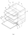
- the Fig.1 shows a schematic perspective view of an embodiment of a household dishwasher 1.
- the household dishwasher 1 comprises a washing container 2 which can be closed by a door 3, in particular in a watertight manner.
- a sealing device can be provided between the door 3 and the washing container 2.
- the washing container 2 is preferably cuboid-shaped.
- the washing container 2 can be arranged in a housing of the household dishwasher 1.
- the washing container 2 and the door 3 can form a washing chamber 4 for washing dishes.
- Door 3 is in the Fig.1 shown in its open position.
- the door 3 can be closed or opened by pivoting about a pivot axis 5 provided at a lower end of the door 3.
- a loading opening 6 of the washing container 2 can be closed or opened.
- the washing container 2 has a base 7, a ceiling 8 arranged opposite the base 7, a rear wall 9 arranged opposite the closed door 3 and two side walls 10, 11 arranged opposite one another.
- the base 7, the ceiling 8, the rear wall 9 and the side walls 10, 11 can be made from a stainless steel sheet, for example.
- the base 7 can be made from a plastic material, for example.
- the household dishwasher 1 further comprises at least one dishware holder 12 to 14.
- dishware holders 12 to 14 can be provided, wherein the dishware holder 12 can be a lower dishware holder or a lower basket, the dishware holder 13 can be an upper dishware holder or an upper basket and the dishware holder 14 can be a cutlery drawer.
- the washware holders 12 to 14 are arranged one above the other in the washing container 2.
- Each washware holder 12 to 14 can be moved either into or out of the washing container 2.
- each washware holder 12 to 14 can be pushed or moved into the washing container 2 in an insertion direction E and pulled or moved out of the washing container 2 in an extraction direction A opposite to the insertion direction E.
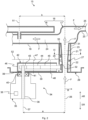
- the Fig. 2 shows a schematic sectional view of an embodiment of a spray device 15 for the household dishwasher 1.
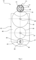
- the Fig.3 shows a schematic Sectional view of the spray device 15 according to the section line III-III of the Fig.2 .
- the following refers to the Fig.2 and 3 referred to at the same time.
- the spray device 15 is arranged inside the washing container 2. In particular, the spray device 15 is positioned below the items to be washed 12. The spray device 15 can be positioned on the floor 7.
- the spray device 15 comprises a spray arm 16 for applying washing liquor and/or fresh water F to items to be washed (not shown) held in the washing container 2.
- the spray arm 16 comprises a boom 17 that is actively driven and a spray arm satellite 18 that is rotatably mounted on the boom 17.
- the spray arm satellite 18 can have a plurality of arms. For example, the spray arm satellite 18 can have three arms that are offset from one another at an angle of 120°.
- the boom 17 can have spray nozzles that are not shown.
- the spray arm satellite 18 is not actively driven. This means that the spray arm satellite 18 does not have its own drive device.
- the spray arm satellite 18 is recoil-driven with the aid of the rinsing liquid and/or the fresh water F.
- "recoil-driven” is to be understood as meaning that the spray arm satellite 18 has several spray nozzles (not shown) through which the rinsing liquid and/or the fresh water F can exit the spray arm satellite 18 and cause it to rotate.
- the boom 17, however, is actively driven in contrast to the spray arm satellite 18.
- the boom 17 can also be recoil-driven.
- the boom 17 comprises a first arm 19, on which the spray arm satellite 18 is rotatably mounted, and a second arm 20.
- the arms 19, 20 can have spray nozzles (not shown).
- two such arms 19, 20 are provided.
- the number of arms 19, 20 is arbitrary. There can also be exactly one arm 19, 20 or more than two arms 19, 20.
- Both the spray arm satellite 18 and the boom 17 are hollow so that the rinsing solution and/or the fresh water F can flow through the boom 17 and the spray arm satellite 18.
- the arms 19, 20 of the boom 17 are connected to a venturi tube or bearing tube 21.
- the bearing tube 21 is a venturi tube or can be referred to as a venturi tube.
- the bearing tube 21 can also be referred to as a bearing part.
- the bearing tube 21 is suitable for supplying the arms 19, 20 with the rinsing solution and/or the fresh water F.
- the bearing tube 21 can be conical.
- a spray arm toothing 22 with a large number of teeth is provided on the outside of the bearing tube 21.
- the arms 19, 20 are made, for example, from polypropylene (PP), in particular glass fiber reinforced polypropylene (PP).
- POM polyoxymethylene
- the bearing tube 21 and the arms 19, 20 can be made from different plastic materials.
- the arms 19, 20 and the bearing tube 21 can be firmly connected to one another in a plastic injection molding process by means of overmolding the various plastic materials.
- the arms 19, 20 can be designed as one piece, in particular as a single piece of material. "One piece” here means that the arms 19, 20 form a common component and are not composed of different components. "One piece of material” here means that the arms 19, 20 are made entirely of the same material. Accordingly, the bearing tube 21 and the spray arm toothing 22 can also be designed as one piece, in particular as a single piece of material.
- the bearing tube 21 comprises on the inside a conical or tapered cavity 23 through which the rinsing liquid and/or the fresh water F can flow into cavities 24, 25 of the arms 19, 20.
- the spray arm 16, in particular the boom 17, is assigned a rotation axis 26 about which the spray arm 16, in particular the boom 17, can rotate.
- a rib geometry 27 running around the rotation axis 26 is provided on the spray arm 16, in particular on the boom 17.
- the rib geometry 27 is provided in particular on the bearing tube 21.
- the rib geometry 27 is formed in one piece, in particular in one piece, with the bearing tube 21.
- the rib geometry 27 runs in a disk shape around the rotation axis 26.
- the rib geometry 27 is arranged between the spray arm teeth 22 and the arms 19, 20.
- the rib geometry 27 is positioned at a distance from the spray arm toothing 22 when viewed along the rotation axis 26.
- the rib geometry 27 comprises a coding groove 28 running along the rotation axis 26, the function of which will be explained below.
- the coding groove 28 represents a interruption of the rib geometry 27. This means that the rib geometry 27 runs completely around the bearing tube 21 except for the coding groove 28.
- the spray device 15 further comprises a pump pot 29.
- the pump pot 29 is preferably a plastic injection-molded component.
- the pump pot 29 has a disk-shaped base section 30. In the orientation of the Fig. 2 On the top, a tubular pump pot dome 31 extends out of the base section 30.
- the pump pot dome 31 extends in the direction of the ceiling 8.
- the bearing tube 21 is accommodated in the pump pot dome 31 and is rotatably mounted. The type of mounting of the bearing tube 21 in the pump pot dome 31 is, however, in the Fig. 2 not shown.
- the pump pot dome 31 comprises a radial opening 32.
- "Radial” is to be understood in relation to a radial direction R of the pump pot dome 31.
- the radial direction R is oriented away from the axis of rotation 26 and perpendicular to it.
- the opening 32 thus breaks through the pump pot dome 31 in the radial direction R.
- the spray arm toothing 22 can be positively engaged through the opening 32, as will be explained below.
- the opening 32 can be rectangular.
- the pump pot dome 31 further comprises a coding rib 33 corresponding to the coding groove 28.
- the coding rib 33 extends from the inside of the tubular pump pot dome 31 in the direction of the bearing tube 21 without contacting it.
- the coding rib 33 runs along the axis of rotation 26.
- the coding rib 33 can be guided through the coding groove 28 along the axis of rotation 26 during assembly and disassembly of the spray arm 16, in particular the boom 17, so that the spray arm 16, in particular the boom 17, can be assembled and disassembled from the pump pot 29 in exactly one angular position.
- the coding rib 33 can have a rectangular or triangular geometry. However, the geometry of the coding rib 33 can also be based on an involute shape of the spray arm toothing 22 or be designed very similarly thereto.
- the coding groove 28 is then designed to correspond thereto.
- the spray device 15 further comprises a drive device 34 for actively driving the spray arm 16.
- the drive device 34 comprises a drive element 35, in particular an electric motor, with a drive shaft 36, which during operation of the drive device 34 rotates about a rotation axis 37.
- “Actively driven” in this case means that the spray arm 16 is set in rotation with the help of the drive element 35 and not with the help of spray nozzles.
- the rotation axis 37 of the drive shaft 36 and the rotation axis 26 of the spray arm 16 are arranged parallel to one another and spaced apart by a distance a.
- the drive element 35 comprises a sensor device 38, with the aid of which an angular position of the drive shaft 36 can be detected.
- the sensor device 38 can comprise, for example, a forked light barrier and a perforated disk or a cam disk and a switching contact or a Hall sensor.
- the type of design of the sensor device 38 is arbitrary. Any type of sensor is suitable for the sensor device 38 with the aid of which the angular position of the drive shaft 36 can be detected.
- the drive shaft 36 is guided through a bore 39 provided in the base section 30 of the pump pot 29.
- the drive shaft 36 is sealed in a fluid-tight manner with respect to a cylindrical receiving section 41 of the pump pot 29 by means of a sealing element 40, in particular by means of a shaft sealing ring.
- the drive device 34 further comprises a gear 42 for transmitting torque from the drive shaft 36 to the spray arm 16, in particular to the spray arm toothing 22 of the boom 17.
- the gear 42 can also be referred to as a gear box, gear module or gear unit.
- the gear 42 can comprise straight-toothed or helical-toothed gears 43 to 45, a bevel gear, a belt drive or a chain drive.
- the gears 43 to 45 bridge the distance a between the drive shaft 36, in particular the axis of rotation 37, and the spray arm 16, in particular the axis of rotation 26.
- the number of gears 43 to 45 is basically arbitrary.
- the transmission 42 comprises a transmission housing 46 in which the gears 43 to 45 are rotatably mounted.
- a first gear 43 is mounted in the transmission housing 46 so as to be rotatable about the rotation axis 37
- a second gear 44 is mounted in the transmission housing 46 so as to be rotatable about a rotation axis 47
- a third gear 45 is mounted in the transmission housing 46 so as to be rotatable about a rotation axis 48.
- the first gear 43 is coupled to the drive shaft 36 in a rotationally fixed manner.
- the drive shaft 36 has an engagement section 49 in the form of a lateral flattening or milling.
- the first gear 43 has a counter-engagement section 50 corresponding to the engagement section 49.
- the engagement section 49 and the counter-engagement section 50 engage with one another in a form-fitting manner.
- a form-fitting connection is created by the engagement or engagement of at least two connection partners, in this case the engagement section 49 and the counter-engagement section 50.
- the engagement section 49 and the counter-engagement section 50 can, however, also be a splined shaft contour with a corresponding coding tooth.
- the third gear 45 is in engagement with the spray arm toothing 22, with the second gear 44 being arranged between the gears 43, 45.
- the axes of rotation 26, 37, 47, 48 are arranged parallel to each other and spaced apart from each other.
- the spray arm satellite 18 rotates about a rotation axis 51 on the boom 17.
- the rotation axes 26, 51 are arranged at a distance b from one another.
- the rotation axes 26, 51 are positioned parallel to one another.
- the pump pot 29 is also assigned a sieve system 52, under which the gear 42 is arranged. This means that the gear 42 is positioned between the base section 30 of the pump pot 29 and the sieve system 52. This can prevent contamination of the gear 42.
- the sieve system 52 can be made up of several parts and can include a fine sieve and a coarse sieve.
- the rinsing liquid and/or the fresh water F is conveyed with the aid of a circulation pump (not shown) and fed to the spray arm 16.
- the rinsing liquid and/or the fresh water F is fed to the spray arm satellite 18 via the boom 17.
- This is set in rotation about the axis of rotation 51 by the rinsing liquid and/or fresh water F emerging from spray nozzles (not shown).
- the spray arm 16 itself is set in rotation about the axis of rotation 26 with the aid of the drive device 34.
- the speed of the boom 17 can be set as desired.
- the speed of the boom 17 can also change during a washing program.
- the boom 17 can also remain in a preselected position so that an intensive rinsing zone can be realized, which is supplied with rinsing liquid and/or fresh water F by means of the spray arm satellite 18 without the boom 17 rotating.
- the spray arm 16 can only be pulled out of the pump pot dome 31 in a withdrawal direction AR along the rotation axis 26 if, as shown in the Fig.3 shown, the coding rib 33 is positioned exactly above the coding groove 28 when viewed along the axis of rotation 26.
- the angular position of the drive shaft 36 of the drive element 35 can be detected with the aid of the sensor device 38. This means that the position of the interlocking gears 43 to 45 is also known.
- the spray arm 16 can only be reassembled if the coding groove 28 is located exactly above the coding rib 33. Only then can the spray arm 16 be pushed or inserted into the pump pot dome 31 in an insertion direction ER such that the spray arm teeth 22 engage positively in the third gear 45.
- the spray arm 16 can always be positioned at 6 o'clock for assembly and disassembly purposes. It is thus possible to determine the angle and control the position of the spray arm 16 via the sensor device 38 of the drive element 35.
Landscapes
- Engineering & Computer Science (AREA)
- Water Supply & Treatment (AREA)
- Washing And Drying Of Tableware (AREA)
Claims (9)
- Lave-vaisselle ménager (1) avec une cuve de lavage (2), un bras d'aspersion (16) pour l'application d'un bain de lavage et/ou d'eau claire (F) sur la vaisselle chargée dans la cuve de lavage (2), un dispositif d'entraînement (34) pour l'entraînement actif du bras d'aspersion (16), et un pot de pompe (29) sur lequel le bras d'aspersion (16) est monté à rotation autour d'un axe de rotation (26), dans lequel le bras d'aspersion (16) comporte un élément à géométrie en ailettes (27) circonférentiel autour de l'axe de rotation (26), lequel comprend une rainure de codage (28) s'étendant le long de l'axe de rotation (26), dans lequel le pot de pompe (29) comporte une ailette de codage (33) correspondant à la rainure de codage (28) et s'étendant le long de l'axe de rotation (26), laquelle peut être passée à travers la rainure de codage (28) lors d'un montage et d'un démontage du bras d'aspersion (16) le long de l'axe de rotation (26) de telle sorte que le bras d'aspersion (16) soit montable dans exactement une position angulaire sur le pot de pompe (29) et démontable de celui-ci, et caractérisé en ce que le pot de pompe (29) comporte un sommet de pot de pompe tubulaire (31) sur lequel le bras d'aspersion (16) est monté à rotation autour de son axe de rotation (26), dans lequel l'ailette de codage (33) est prévue sur la face intérieure au niveau du sommet de pot de pompe (31).
- Lave-vaisselle ménager selon la revendication 1, caractérisé en ce que le dispositif d'entraînement (34) comporte un élément d'entraînement (35) avec un arbre d'entraînement (36) qui est rotatif autour d'un axe de rotation (37).
- Lave-vaisselle ménager selon la revendication 2, caractérisé en ce que l'axe de rotation (26) du bras d'aspersion (16) et l'axe de rotation (37) de l'arbre d'entraînement (36) sont parallèles l'un à l'autre et disposés de manière espacée l'un de l'autre.
- Lave-vaisselle ménager selon la revendication 3, caractérisé par une transmission (42) qui comble une distance (a) entre l'axe de rotation (26) du bras d'aspersion (16) et l'axe de rotation (37) de l'arbre d'entraînement (36).
- Lave-vaisselle ménager selon la revendication 4, caractérisé en ce que l'arbre d'entraînement (36) comporte une section d'engrènement (49), laquelle est conçue pour s'engrener par complémentarité de forme dans une section de contre-engrènement (50) correspondante d'une roue dentée (43) de la transmission (42) de telle sorte que la roue dentée (43) soit montable dans exactement une position angulaire sur l'arbre d'entraînement (36).
- Lave-vaisselle ménager selon la revendication 5, caractérisé en ce que la transmission (42) comporte plusieurs roues dentées (43 à 45), parmi lesquelles une roue dentée (43) est montée sur l'arbre d'entraînement (36) et une autre roue dentée (45) s'engrène par complémentarité de forme dans une denture de bras d'aspersion (22) du bras d'aspersion (16).
- Lave-vaisselle ménager selon la revendication 6, caractérisé en ce que l'élément à géométrie en ailettes (27) est disposé de manière espacée de la denture de bras d'aspersion (22), vu le long de l'axe de rotation (26) du bras d'aspersion (16).
- Lave-vaisselle ménager selon l'une des revendications 2 à 7, caractérisé en ce que l'élément d'entraînement (35) comporte un dispositif de détection (38) pour l'enregistrement d'une position angulaire de l'arbre d'entraînement (36).
- Lave-vaisselle ménager selon l'une des revendications 1 à 8, caractérisé en ce que le bras d'aspersion (16) comporte une potence (17) montée à rotation sur le pot de pompe (29), laquelle est entraînée activement par le dispositif d'entraînement (34), et un satellite de bras d'aspersion (18) monté à rotation sur la potence (17).
Applications Claiming Priority (2)
| Application Number | Priority Date | Filing Date | Title |
|---|---|---|---|
| DE102019211403.2A DE102019211403A1 (de) | 2019-07-31 | 2019-07-31 | Haushalts-Geschirrspülmaschine |
| PCT/EP2020/070116 WO2021018614A1 (fr) | 2019-07-31 | 2020-07-16 | Lave-vaisselle ménager |
Publications (2)
| Publication Number | Publication Date |
|---|---|
| EP4003129A1 EP4003129A1 (fr) | 2022-06-01 |
| EP4003129B1 true EP4003129B1 (fr) | 2024-09-18 |
Family
ID=71741781
Family Applications (1)
| Application Number | Title | Priority Date | Filing Date |
|---|---|---|---|
| EP20744000.9A Active EP4003129B1 (fr) | 2019-07-31 | 2020-07-16 | Lave-vaisselle ménager |
Country Status (5)
| Country | Link |
|---|---|
| US (1) | US11696667B2 (fr) |
| EP (1) | EP4003129B1 (fr) |
| CN (1) | CN114206188B (fr) |
| DE (1) | DE102019211403A1 (fr) |
| WO (1) | WO2021018614A1 (fr) |
Families Citing this family (1)
| Publication number | Priority date | Publication date | Assignee | Title |
|---|---|---|---|---|
| DE102021205923A1 (de) * | 2021-06-11 | 2022-12-15 | BSH Hausgeräte GmbH | Haushalts-Geschirrspülmaschine und Verfahren |
Family Cites Families (15)
| Publication number | Priority date | Publication date | Assignee | Title |
|---|---|---|---|---|
| DE10351785A1 (de) * | 2003-11-06 | 2005-06-09 | BSH Bosch und Siemens Hausgeräte GmbH | Vorrichtung zur Ansteuerung von Sprühkanälen in Geschirrspülmaschinen |
| DE102010042576A1 (de) * | 2010-10-18 | 2012-04-19 | BSH Bosch und Siemens Hausgeräte GmbH | Geschirrspülmaschine mit zumindest einer Sprüheinrichtung |
| DE102011089319B3 (de) | 2011-12-20 | 2013-03-14 | BSH Bosch und Siemens Hausgeräte GmbH | Geschirrspülmaschine mit in Längsrichtung beweglichem Sprüharm |
| US9763554B2 (en) * | 2012-02-14 | 2017-09-19 | Premark Feg L.L.G. | Warewash machine with removable rotating arm and related method |
| ITTO20120200A1 (it) | 2012-03-08 | 2013-09-09 | Bitron Spa | Dispositivo per la movimentazione di giranti di lavaggio per dispositivi di lavaggio e o asciugatura. |
| US9220393B2 (en) * | 2012-09-13 | 2015-12-29 | Whirlpool Corporation | Dishwasher with controlled rotation of lower spray arm |
| RU2647139C2 (ru) * | 2013-12-20 | 2018-03-14 | Электролюкс Апплайнсиз Актиеболаг | Устройство в посудомоечной машине, предназначенное для создания зоны мытья с выбираемым положением |
| US9655494B2 (en) | 2014-06-05 | 2017-05-23 | Wolf Appliance, Inc. | Dishwasher filtration system |
| CN104523208B (zh) * | 2015-01-08 | 2017-08-25 | 佛山市顺德区美的洗涤电器制造有限公司 | 喷臂装置及洗碗机 |
| CN106821250B (zh) * | 2015-02-02 | 2019-01-22 | Lg电子株式会社 | 洗碗机 |
| US9687137B2 (en) * | 2015-06-15 | 2017-06-27 | Haier Us Appliance Solutions, Inc. | Diverter for selective fluid flow in a dishwashing appliance |
| KR101737845B1 (ko) * | 2015-08-03 | 2017-05-19 | 엘지전자 주식회사 | 식기세척기 |
| CN206473287U (zh) * | 2016-10-20 | 2017-09-08 | 珠海格力电器股份有限公司 | 洗碗机喷淋装置及洗碗机 |
| IT201700031111A1 (it) * | 2017-03-21 | 2018-09-21 | Candy Spa | Macchina lavastoviglie con braccio spruzzatore roto-traslante |
| KR102527574B1 (ko) * | 2018-02-12 | 2023-04-28 | 엘지전자 주식회사 | 식기세척기 |
-
2019
- 2019-07-31 DE DE102019211403.2A patent/DE102019211403A1/de active Pending
-
2020
- 2020-07-16 WO PCT/EP2020/070116 patent/WO2021018614A1/fr not_active Ceased
- 2020-07-16 EP EP20744000.9A patent/EP4003129B1/fr active Active
- 2020-07-16 CN CN202080055873.6A patent/CN114206188B/zh active Active
- 2020-07-16 US US17/427,932 patent/US11696667B2/en active Active
Also Published As
| Publication number | Publication date |
|---|---|
| US20220087501A1 (en) | 2022-03-24 |
| DE102019211403A1 (de) | 2021-02-04 |
| WO2021018614A1 (fr) | 2021-02-04 |
| US11696667B2 (en) | 2023-07-11 |
| CN114206188B (zh) | 2024-01-26 |
| EP4003129A1 (fr) | 2022-06-01 |
| CN114206188A (zh) | 2022-03-18 |
Similar Documents
| Publication | Publication Date | Title |
|---|---|---|
| DE69518046T2 (de) | Sprühmethode für Geschirrspüler und Vorrichtung für deren Durchführung | |
| EP1731081B1 (fr) | Lave-vaisselle | |
| DE19832982C2 (de) | Spülvorrichtung für eine Geschirrspülmaschine | |
| DE60223265T2 (de) | Geschirrspülmaschine mit Flachfiltereinrichtung umfassend Bereiche mit unterschiedlichen Lochdimensionen | |
| EP1062049B1 (fr) | Dispositif de nettoyage de reservoir | |
| DE102023103570B3 (de) | Filtrationseinrichtung für ein wasserführendes Haushaltsgerät | |
| EP4003127B1 (fr) | Lave-vaisselle domestique | |
| DE2820311A1 (de) | Zugabevorrichtung fuer die eingabe eines zusatzmittels in die waschkammer einer geschirrspuel- oder waschmaschine | |
| EP4003126B1 (fr) | Lave-vaisselle domestique | |
| EP2452607A2 (fr) | Agencement de bras de lavage pour un chariot de réception de linge de plusieurs jours | |
| EP0292664A2 (fr) | Outil pour la préparation des aliments | |
| DE102019211403A1 (de) | Haushalts-Geschirrspülmaschine | |
| DE102018212992B3 (de) | Wasserweiche für eine Haushalts-Geschirrspülmaschine | |
| DE102008054392A1 (de) | Mitnehmer, Wäschetrommel und Waschmaschine | |
| DE69721211T2 (de) | Geschirrspülmaschine mit einem Ober- und Untersprüharm, einer Umwälzpumpe und einer Entleerungspumpe | |
| WO2020078705A2 (fr) | Lave-vaisselle ménager pourvu d'un système de filtre autonettoyant | |
| EP4003128B1 (fr) | Lave-vaisselle à usage domestique | |
| DE3043657C2 (fr) | ||
| DE4220234C2 (de) | Küchenmaschine | |
| EP2606805A1 (fr) | Lave-vaisselle équipé d'un bras pulvérisateur se déplaçant dans le sens de la longueur | |
| CH617974A5 (en) | Washing machine | |
| DE2741729A1 (de) | Filtereinrichtung zum filtern staubhaltiger luft | |
| EP4004267A1 (fr) | Lave-vaisselle ménager et procédé de fonctionnement d'un lave-vaisselle ménager | |
| DE69312979T2 (de) | Geschirrspüler mit Ablaufwanne | |
| DE113050T1 (de) | Filtertrommel. |
Legal Events
| Date | Code | Title | Description |
|---|---|---|---|
| STAA | Information on the status of an ep patent application or granted ep patent |
Free format text: STATUS: UNKNOWN |
|
| STAA | Information on the status of an ep patent application or granted ep patent |
Free format text: STATUS: THE INTERNATIONAL PUBLICATION HAS BEEN MADE |
|
| PUAI | Public reference made under article 153(3) epc to a published international application that has entered the european phase |
Free format text: ORIGINAL CODE: 0009012 |
|
| STAA | Information on the status of an ep patent application or granted ep patent |
Free format text: STATUS: REQUEST FOR EXAMINATION WAS MADE |
|
| 17P | Request for examination filed |
Effective date: 20220228 |
|
| AK | Designated contracting states |
Kind code of ref document: A1 Designated state(s): AL AT BE BG CH CY CZ DE DK EE ES FI FR GB GR HR HU IE IS IT LI LT LU LV MC MK MT NL NO PL PT RO RS SE SI SK SM TR |
|
| DAV | Request for validation of the european patent (deleted) | ||
| DAX | Request for extension of the european patent (deleted) | ||
| GRAP | Despatch of communication of intention to grant a patent |
Free format text: ORIGINAL CODE: EPIDOSNIGR1 |
|
| STAA | Information on the status of an ep patent application or granted ep patent |
Free format text: STATUS: GRANT OF PATENT IS INTENDED |
|
| RIC1 | Information provided on ipc code assigned before grant |
Ipc: A47L 15/42 20060101ALN20240429BHEP Ipc: A47L 15/22 20060101AFI20240429BHEP |
|
| INTG | Intention to grant announced |
Effective date: 20240521 |
|
| GRAS | Grant fee paid |
Free format text: ORIGINAL CODE: EPIDOSNIGR3 |
|
| GRAA | (expected) grant |
Free format text: ORIGINAL CODE: 0009210 |
|
| STAA | Information on the status of an ep patent application or granted ep patent |
Free format text: STATUS: THE PATENT HAS BEEN GRANTED |
|
| AK | Designated contracting states |
Kind code of ref document: B1 Designated state(s): AL AT BE BG CH CY CZ DE DK EE ES FI FR GB GR HR HU IE IS IT LI LT LU LV MC MK MT NL NO PL PT RO RS SE SI SK SM TR |
|
| REG | Reference to a national code |
Ref country code: GB Ref legal event code: FG4D Free format text: NOT ENGLISH |
|
| REG | Reference to a national code |
Ref country code: CH Ref legal event code: EP |
|
| REG | Reference to a national code |
Ref country code: DE Ref legal event code: R096 Ref document number: 502020009281 Country of ref document: DE |
|
| REG | Reference to a national code |
Ref country code: IE Ref legal event code: FG4D Free format text: LANGUAGE OF EP DOCUMENT: GERMAN |
|
| REG | Reference to a national code |
Ref country code: LT Ref legal event code: MG9D |
|
| PG25 | Lapsed in a contracting state [announced via postgrant information from national office to epo] |
Ref country code: NO Free format text: LAPSE BECAUSE OF FAILURE TO SUBMIT A TRANSLATION OF THE DESCRIPTION OR TO PAY THE FEE WITHIN THE PRESCRIBED TIME-LIMIT Effective date: 20241218 |
|
| PG25 | Lapsed in a contracting state [announced via postgrant information from national office to epo] |
Ref country code: GR Free format text: LAPSE BECAUSE OF FAILURE TO SUBMIT A TRANSLATION OF THE DESCRIPTION OR TO PAY THE FEE WITHIN THE PRESCRIBED TIME-LIMIT Effective date: 20241219 Ref country code: FI Free format text: LAPSE BECAUSE OF FAILURE TO SUBMIT A TRANSLATION OF THE DESCRIPTION OR TO PAY THE FEE WITHIN THE PRESCRIBED TIME-LIMIT Effective date: 20240918 |
|
| PG25 | Lapsed in a contracting state [announced via postgrant information from national office to epo] |
Ref country code: BG Free format text: LAPSE BECAUSE OF FAILURE TO SUBMIT A TRANSLATION OF THE DESCRIPTION OR TO PAY THE FEE WITHIN THE PRESCRIBED TIME-LIMIT Effective date: 20240918 |
|
| PG25 | Lapsed in a contracting state [announced via postgrant information from national office to epo] |
Ref country code: LV Free format text: LAPSE BECAUSE OF FAILURE TO SUBMIT A TRANSLATION OF THE DESCRIPTION OR TO PAY THE FEE WITHIN THE PRESCRIBED TIME-LIMIT Effective date: 20240918 |
|
| PG25 | Lapsed in a contracting state [announced via postgrant information from national office to epo] |
Ref country code: HR Free format text: LAPSE BECAUSE OF FAILURE TO SUBMIT A TRANSLATION OF THE DESCRIPTION OR TO PAY THE FEE WITHIN THE PRESCRIBED TIME-LIMIT Effective date: 20240918 |
|
| REG | Reference to a national code |
Ref country code: NL Ref legal event code: MP Effective date: 20240918 |
|
| PG25 | Lapsed in a contracting state [announced via postgrant information from national office to epo] |
Ref country code: RS Free format text: LAPSE BECAUSE OF FAILURE TO SUBMIT A TRANSLATION OF THE DESCRIPTION OR TO PAY THE FEE WITHIN THE PRESCRIBED TIME-LIMIT Effective date: 20241218 |
|
| PG25 | Lapsed in a contracting state [announced via postgrant information from national office to epo] |
Ref country code: RS Free format text: LAPSE BECAUSE OF FAILURE TO SUBMIT A TRANSLATION OF THE DESCRIPTION OR TO PAY THE FEE WITHIN THE PRESCRIBED TIME-LIMIT Effective date: 20241218 Ref country code: NO Free format text: LAPSE BECAUSE OF FAILURE TO SUBMIT A TRANSLATION OF THE DESCRIPTION OR TO PAY THE FEE WITHIN THE PRESCRIBED TIME-LIMIT Effective date: 20241218 Ref country code: LV Free format text: LAPSE BECAUSE OF FAILURE TO SUBMIT A TRANSLATION OF THE DESCRIPTION OR TO PAY THE FEE WITHIN THE PRESCRIBED TIME-LIMIT Effective date: 20240918 Ref country code: HR Free format text: LAPSE BECAUSE OF FAILURE TO SUBMIT A TRANSLATION OF THE DESCRIPTION OR TO PAY THE FEE WITHIN THE PRESCRIBED TIME-LIMIT Effective date: 20240918 Ref country code: GR Free format text: LAPSE BECAUSE OF FAILURE TO SUBMIT A TRANSLATION OF THE DESCRIPTION OR TO PAY THE FEE WITHIN THE PRESCRIBED TIME-LIMIT Effective date: 20241219 Ref country code: FI Free format text: LAPSE BECAUSE OF FAILURE TO SUBMIT A TRANSLATION OF THE DESCRIPTION OR TO PAY THE FEE WITHIN THE PRESCRIBED TIME-LIMIT Effective date: 20240918 Ref country code: BG Free format text: LAPSE BECAUSE OF FAILURE TO SUBMIT A TRANSLATION OF THE DESCRIPTION OR TO PAY THE FEE WITHIN THE PRESCRIBED TIME-LIMIT Effective date: 20240918 |
|
| PG25 | Lapsed in a contracting state [announced via postgrant information from national office to epo] |
Ref country code: NL Free format text: LAPSE BECAUSE OF FAILURE TO SUBMIT A TRANSLATION OF THE DESCRIPTION OR TO PAY THE FEE WITHIN THE PRESCRIBED TIME-LIMIT Effective date: 20240918 |
|
| PG25 | Lapsed in a contracting state [announced via postgrant information from national office to epo] |
Ref country code: PT Free format text: LAPSE BECAUSE OF FAILURE TO SUBMIT A TRANSLATION OF THE DESCRIPTION OR TO PAY THE FEE WITHIN THE PRESCRIBED TIME-LIMIT Effective date: 20250120 Ref country code: IS Free format text: LAPSE BECAUSE OF FAILURE TO SUBMIT A TRANSLATION OF THE DESCRIPTION OR TO PAY THE FEE WITHIN THE PRESCRIBED TIME-LIMIT Effective date: 20250118 |
|
| PG25 | Lapsed in a contracting state [announced via postgrant information from national office to epo] |
Ref country code: RO Free format text: LAPSE BECAUSE OF FAILURE TO SUBMIT A TRANSLATION OF THE DESCRIPTION OR TO PAY THE FEE WITHIN THE PRESCRIBED TIME-LIMIT Effective date: 20240918 Ref country code: SM Free format text: LAPSE BECAUSE OF FAILURE TO SUBMIT A TRANSLATION OF THE DESCRIPTION OR TO PAY THE FEE WITHIN THE PRESCRIBED TIME-LIMIT Effective date: 20240918 |
|
| PG25 | Lapsed in a contracting state [announced via postgrant information from national office to epo] |
Ref country code: ES Free format text: LAPSE BECAUSE OF FAILURE TO SUBMIT A TRANSLATION OF THE DESCRIPTION OR TO PAY THE FEE WITHIN THE PRESCRIBED TIME-LIMIT Effective date: 20240918 |
|
| PG25 | Lapsed in a contracting state [announced via postgrant information from national office to epo] |
Ref country code: EE Free format text: LAPSE BECAUSE OF FAILURE TO SUBMIT A TRANSLATION OF THE DESCRIPTION OR TO PAY THE FEE WITHIN THE PRESCRIBED TIME-LIMIT Effective date: 20240918 |
|
| PG25 | Lapsed in a contracting state [announced via postgrant information from national office to epo] |
Ref country code: CZ Free format text: LAPSE BECAUSE OF FAILURE TO SUBMIT A TRANSLATION OF THE DESCRIPTION OR TO PAY THE FEE WITHIN THE PRESCRIBED TIME-LIMIT Effective date: 20240918 Ref country code: PL Free format text: LAPSE BECAUSE OF FAILURE TO SUBMIT A TRANSLATION OF THE DESCRIPTION OR TO PAY THE FEE WITHIN THE PRESCRIBED TIME-LIMIT Effective date: 20240918 |
|
| PG25 | Lapsed in a contracting state [announced via postgrant information from national office to epo] |
Ref country code: SK Free format text: LAPSE BECAUSE OF FAILURE TO SUBMIT A TRANSLATION OF THE DESCRIPTION OR TO PAY THE FEE WITHIN THE PRESCRIBED TIME-LIMIT Effective date: 20240918 Ref country code: IT Free format text: LAPSE BECAUSE OF FAILURE TO SUBMIT A TRANSLATION OF THE DESCRIPTION OR TO PAY THE FEE WITHIN THE PRESCRIBED TIME-LIMIT Effective date: 20240918 |
|
| REG | Reference to a national code |
Ref country code: DE Ref legal event code: R097 Ref document number: 502020009281 Country of ref document: DE |
|
| PG25 | Lapsed in a contracting state [announced via postgrant information from national office to epo] |
Ref country code: DK Free format text: LAPSE BECAUSE OF FAILURE TO SUBMIT A TRANSLATION OF THE DESCRIPTION OR TO PAY THE FEE WITHIN THE PRESCRIBED TIME-LIMIT Effective date: 20240918 |
|
| PLBE | No opposition filed within time limit |
Free format text: ORIGINAL CODE: 0009261 |
|
| STAA | Information on the status of an ep patent application or granted ep patent |
Free format text: STATUS: NO OPPOSITION FILED WITHIN TIME LIMIT |
|
| 26N | No opposition filed |
Effective date: 20250619 |
|
| PG25 | Lapsed in a contracting state [announced via postgrant information from national office to epo] |
Ref country code: SE Free format text: LAPSE BECAUSE OF FAILURE TO SUBMIT A TRANSLATION OF THE DESCRIPTION OR TO PAY THE FEE WITHIN THE PRESCRIBED TIME-LIMIT Effective date: 20240918 |
|
| PGFP | Annual fee paid to national office [announced via postgrant information from national office to epo] |
Ref country code: DE Payment date: 20250731 Year of fee payment: 6 |
|
| REG | Reference to a national code |
Ref country code: CH Ref legal event code: H13 Free format text: ST27 STATUS EVENT CODE: U-0-0-H10-H13 (AS PROVIDED BY THE NATIONAL OFFICE) Effective date: 20260224 |
|
| PG25 | Lapsed in a contracting state [announced via postgrant information from national office to epo] |
Ref country code: LU Free format text: LAPSE BECAUSE OF NON-PAYMENT OF DUE FEES Effective date: 20250716 |
|
| GBPC | Gb: european patent ceased through non-payment of renewal fee |
Effective date: 20250716 |
|
| REG | Reference to a national code |
Ref country code: BE Ref legal event code: MM Effective date: 20250731 |
|
| PG25 | Lapsed in a contracting state [announced via postgrant information from national office to epo] |
Ref country code: GB Free format text: LAPSE BECAUSE OF NON-PAYMENT OF DUE FEES Effective date: 20250716 |
|
| PG25 | Lapsed in a contracting state [announced via postgrant information from national office to epo] |
Ref country code: BE Free format text: LAPSE BECAUSE OF NON-PAYMENT OF DUE FEES Effective date: 20250731 |
|
| PG25 | Lapsed in a contracting state [announced via postgrant information from national office to epo] |
Ref country code: FR Free format text: LAPSE BECAUSE OF NON-PAYMENT OF DUE FEES Effective date: 20250731 |
|
| PG25 | Lapsed in a contracting state [announced via postgrant information from national office to epo] |
Ref country code: CH Free format text: LAPSE BECAUSE OF NON-PAYMENT OF DUE FEES Effective date: 20250731 |