EP4003219B1 - Munddusche mit rückflussverhinderung - Google Patents
Munddusche mit rückflussverhinderung Download PDFInfo
- Publication number
- EP4003219B1 EP4003219B1 EP20745202.0A EP20745202A EP4003219B1 EP 4003219 B1 EP4003219 B1 EP 4003219B1 EP 20745202 A EP20745202 A EP 20745202A EP 4003219 B1 EP4003219 B1 EP 4003219B1
- Authority
- EP
- European Patent Office
- Prior art keywords
- channel
- irrigator
- nozzle
- fluid
- oral
- Prior art date
- Legal status (The legal status is an assumption and is not a legal conclusion. Google has not performed a legal analysis and makes no representation as to the accuracy of the status listed.)
- Active
Links
Images


Classifications
-
- A—HUMAN NECESSITIES
- A61—MEDICAL OR VETERINARY SCIENCE; HYGIENE
- A61C—DENTISTRY; APPARATUS OR METHODS FOR ORAL OR DENTAL HYGIENE
- A61C17/00—Devices for cleaning, polishing, rinsing or drying teeth, teeth cavities or prostheses; Saliva removers; Dental appliances for receiving spittle
- A61C17/02—Rinsing or air-blowing devices, e.g. using fluid jets or comprising liquid medication
- A61C17/0202—Hand-pieces
Definitions
- the present disclosure is directed to oral irrigators, and in particular, to mechanisms for oral irrigators to provide back flow prevention.
- JP 2015 217175 A describes an oral cavity washing device including: a tank for storing a washing liquid; a body on which the tank is mounted; a washing unit including a discharge port for discharging the washing liquid; and a tube for connecting the body and the washing unit.
- the oral cavity washing device further includes: a washing passage formed at the body, the tube and the washing unit and for communicating the tank and the discharge port; a pump for discharging the washing liquid stored in the tank to the tube; and an intake passage for supplying air to the washing passage.
- the oral cavity washing device further includes a switch mounted on the washing unit and for opening and closing the intake passage.
- US 2015/148782 A1 describes a delivery device used to deliver a volume of biotechnology treatments to specific areas of the oral cavity or other tissues.
- the treatments and/or therapeutic agents may be delivered to the interproximal area between and around the teeth.
- JP S63 125252 A describes a water supply device for an oral cavity cleaner.
- the device comprises a spinning check valve to reduce the amount of a foreign substance trapped within the seal of the check valve.
- Oral irrigators use a pressurized fluid stream for interdental cleaning and plaque removal.
- pressurized fluid presents a means of potential contamination risk between multiple users of an oral irrigator. For example, when the irrigator is turned off, pressure from the fluid elevated in the nozzle creates a back-siphon, also called backflow, that can pull fluid from a user's mouth into the nozzle and further into the irrigator fluid pathway.
- Fluid in a user's mouth can contain a combination of bodily fluids such as saliva and blood. Exposure to another individual's saliva and blood presents the risk of transmission of saliva or blood borne pathogens.
- pathogens are spread between people through the transmission of bodily fluids, the most common of which are HIV, Hepatitis B, and Hepatitis C. Contracting these pathogens can result in short term and long term health issues.
- Certain pathogens, specifically Hepatitis C are capable of living outside a human host for prolonged periods and do not have immediate symptoms. As such, many who carry the pathogen are unaware they have been exposed until symptoms develop later in life. This makes Hepatitis C of particular risk for shared devices that are exposed to bodily fluids.
- the present disclosure is directed to mechanisms for oral irrigators to provide back flow prevention.
- the oral irrigator comprises a reservoir, pump, tether, irrigator handle, and irrigator nozzle.
- An arrowhead check valve comprising a resilient element and an elastic head element is inserted in the irrigator nozzle, irrigator handle, or irrigator tether, to prevent backflow of contaminated fluid from a user's saliva or blood, especially when the nozzle is removed and the irrigator is shared between multiple users.
- the elastic head element comprises: an elongated portion having a first end and a second end; a frustoconical portion integrally connected to the elongated portion; and, a circular lip or a plurality of tabs integrally connected to the elongated portion.
- the frustoconical portion of the elastic head element comprises a frustoconical surface arranged to contact and deform when in contact with an inner surface of a first channel, which extends within the irrigator nozzle, an inner surface of a second channel, which extends within the irrigator handle, or an inner surface of a third channel, which extends win the irrigator tether.
- the circular lip or the plurality of tabs of the elastic head element comprise one or more surfaces facing the first end of the elongated portion, the one or more surfaces arranged to contact and deform when in contact with the resilient element.
- a first portion of the elongated portion of the elastic head element is arranged within a cavity of the resilient element.
- the nozzle is secured to the handle utilizing a clip, the clip having a first end and a second end and arranged to move from a first position to a second position, wherein in the first position the second end of the clip secures the nozzle.
- the second channel further comprises a sealing member arranged within a second end of the handle.
- the arrowhead check valve comprises a resilient element, such as a spring, and an elastic head element, which further comprises: an elongated portion having a first end and a second end; a frustoconical portion integrally connected to the elongated portion; and a circular lip or a plurality of tabs integrally connected to the elongated portion.
- a resilient element such as a spring
- an elastic head element which further comprises: an elongated portion having a first end and a second end; a frustoconical portion integrally connected to the elongated portion; and a circular lip or a plurality of tabs integrally connected to the elongated portion.
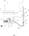
- FIG. 1 is a schematic illustration of an oral irrigator system 100.
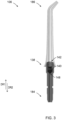
- Oral irrigator 100 includes irrigator tip 102 having a handle 104 and a nozzle 106. Irrigator tip 102 further includes a first channel 108, which extends within and through the nozzle portion 106, and second channel 110, which extends within the handle 104 and is in fluid communication with the first channel 108.
- Oral irrigator 100 further includes housing 112 which contains reservoir 114, pump 116, and power supply 118.
- Reservoir 114 contains a volume of fluid 120 which during operation of oral irrigator 100 is directed through irrigator tip 102 into the mouth of user U.
- Pump 116 comprises motor 122, crank 124, and piston 126. Motor 122, crank 124, and piston 126 work in concert to create a pressurized environment that facilitates flow 128 from reservoir 114, through tether 130, into irrigator tip 102 and into user U's mouth.
- Tether 130 is a substantially hollow, flexible tube, having a first end 132 and a second end 134.
- a third channel 136 is arranged between the first end 132 and the second end 134 of the tether 130.
- the first end 132 of tether 130 is fixedly secured to the handle 104 of the irrigator tip 102 and in fluid communication with the second channel 110, and the second end 134 of tether 130 is fixedly secured to pump 116 and in fluid communication with the pump 116.
- the third channel 136 is in fluid communication with the second channel 110, and the pump 116 is in fluid communication with the third channel 136.
- Tether 130 functions as a conduit through which flow 128 of fluid 120 proceeds from reservoir 114 to irrigator tip 102 and into user U's mouth for cleaning, through the first channel 108, the second channel 110, and the third channel 136.
- Fluid 120 can be selected from, for example, water, a water-gas mixture, oral cleansing concentrate, standard or antiseptic (alcohol based) mouthwash, or any fluid 120 with a viscosity low enough to proceed through the first channel 108, the second channel 110, and third channel 136.
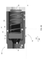
- the oral irrigator system 100 further comprises an arrowhead check valve 138 comprising an elastic head element 140 and a resilient element 142.
- the arrowhead check valve 138 has an inlet 144 and an outlet 146 to allow fluid 120 to flow 128 through the valve 138 when the valve 138 is open and when the flow 128 provides enough pressure to open the valve 138.
- the arrowhead check valve 138 may be arranged, for example, within the first channel 108, with the second channel 110, or within the third channel 136 (shown in FIG. 1 ).
- the elastic head element 140 seals the flow 128 by making contact with an inner surface 148 (shown in FIG.
- the arrowhead check valve 138 is placed in the nozzle 106, removal of the nozzle 106 removes the potentially contamination fluid from the system. Placing the arrowhead check valve 138 in the nozzle also eliminates the risk for diffusion of bodily fluids through the fluid channels. By placing the arrowhead check valve 138 in handle 104 of the irrigator tip 102, the portion of fluid pathway that is at risk for cross contamination due to diffusion or from spilled fluid during nozzle 106 removal is reduced.
- arrowhead check valve 138 is placed in the handle 104 of the oral irrigator 100 as close to the nozzle 106 as possible. It should be appreciated that alternative locations for placement of the arrowhead check valve 138 in the handle 104 may also be utilized.
- the resilient element 142 is a spring, having a cavity 154 through the center of the spring 142 which lies along a first axis A1.
- the elastic head element 140 further comprises an elongated portion 156, having a first end 158 and a second end 160, which extends along the first axis A1.
- a first portion 162 of the elongated portion 156 which begins at the first end 158 of the elongated portion 156, is arranged within the cavity 154 of the resilient element 142.
- a second portion 164 of the elongated portion 156 extends from the first portion 162 to the second end 160 of the elongated portion 156.
- a plurality of tabs 166 adjacent to the second end 160 of the elongated portion 156 are a plurality of tabs 166 (shown in FIG. 2A ).
- the plurality of tabs 166 extend along the second axis A2 which are orthogonal to the first axis A1.
- Each tab of the plurality of tabs 166 has a surface 168 which faces the first end 158 of the elongated portion 156.
- Each surface 168 of each tab of the plurality of tabs 166 makes contact with the resilient element 142.
- a circular lip 170 adjacent to the second end 160 of the elongated portion 156, along a second axis A2, which is orthogonal to the first axis A1, is a circular lip 170 (shown in FIG. 2B ).
- the circular lip 170 has a surface 172 which faces the first end 158 of the elongated portion 156, where the surface 172 makes contact with the resilient element 142.
- a frustoconical portion 174 of the elastic head element 140 Adjacent to the second end 160 of the elongated portion 156 is a frustoconical portion 174 of the elastic head element 140.
- the frustoconical portion 174 has a first surface 176 which connects with the second end 160 of the elongated portion 156 and a frustoconical surface 178.
- the frustoconical surface 178 is arranged to contact and deform when in contact with an inner surface 148 of the first channel 108 (shown in FIG. 3 ), an inner surface 150 of the second channel 110 (shown in FIG. 4 ), or an inner surface 152 of the third channel 136 (shown in FIG. 2B ), depending on where the arrowhead check valve 138 is located, for example, in the nozzle 106 of the oral irrigator 100, in the handle 104 of the oral irrigator 100, or in the tether 130 of the oral irrigator 100.
- fluid 120 flows 128 through the oral irrigator 100, it flows 128 from the pump 116 to the second end 134 of the tether 130 and to the first end 132 of the tether 130 through the third channel 136. Fluid 120 then flows 128 from the first end 180 of the handle 104 to the second end 182 of the handle 104 through the second channel 110. The fluid 120 then flows from the first end 184 of the nozzle 106 to the second end 186 of the nozzle 106 through the first channel 108 (shown in FIG. 3 ) and into the user U's mouth.
- arrowhead check valve 138 is arranged in the handle 104 of the oral irrigator 100.
- the fluid 120 When fluid 120 flows from the first end 180 of the handle 104 to the second end 182 of the handle 104, the fluid 120 creates a force in the first direction DR1 through the second channel 110.
- This force moves the elastic head element 140 in the first direction DR1.
- the elastic head element 140 which was previously in contact with an inner surface of the second channel 150 and blocking flow 128, is moved in the first direction DR1, which opens the second channel 110 for fluid 120 flow 128.
- the force in the first direction DR1 is also applied to the resilient element 142, which may be, for example, a spring.
- the elastic head element 140 is in contact with the resilient element 142 via one or more surfaces 168 of the plurality of tab 166 or a surface 172 of the circular lip 170.
- the force on the elastic head element 140 and the fluid 120 flow 128 through the second channel 110 compresses the resilient element 142.
- the elastic head element 140 provides for an even distribution of pressure on the elastic head element 140 by the resilient element 142, so that the elastic head element 140 does not deform when the valve is closed and a good seal is made between the frustoconical portion 174 and the inner surface of the second channel 150. Additionally, the arrangement of the first portion 162 of the elongated portion 156 of the elastic head element 140 within a cavity 154 of the resilient element 142 allows for the elastic head element 140 to remain aligned as the valve is opened and closed, which provides for a tight seal and prevents leaks.
- This arrangement of the arrowhead check valve 138 make the valve self-sealing to prevent backflow in the event the oral irrigator 100 is turned off before the risk of backflow is removed, for example, by a user U removing the nozzle 106 from the mouth.
Landscapes
- Health & Medical Sciences (AREA)
- Dentistry (AREA)
- Epidemiology (AREA)
- Life Sciences & Earth Sciences (AREA)
- Animal Behavior & Ethology (AREA)
- General Health & Medical Sciences (AREA)
- Public Health (AREA)
- Veterinary Medicine (AREA)
- Infusion, Injection, And Reservoir Apparatuses (AREA)
- Surgical Instruments (AREA)
Claims (4)
- Mundduschensystem (100), umfassend:eine Irrigatorspitze (102), wobei die Irrigatorspitze umfasst:eine Düse (106), die einen ersten Kanal (108) umfasst;einen Griff (104), der einen zweiten Kanal (110) in strömungstechnischer Kommunikation mit dem ersten Kanal umfasst;ein Halteband (130), das ein erstes Ende (132) und ein zweites Ende (134) aufweist, wobei zwischen dem ersten Ende und dem zweiten Ende ein dritter Kanal (136) angeordnet ist und das erste Ende des Haltebandes in strömungstechnischer Kommunikation mit dem zweiten Kanal steht;ein Reservoir (114), das eine Flüssigkeit (120) enthält, wobei das Reservoir in strömungstechnischer Kommunikation mit einer Pumpe (116) steht, wobei die Pumpe in strömungstechnischer Kommunikation mit dem dritten Kanal und dem zweiten Ende des Haltebands steht; undein Pfeilkopf-Rückschlagventil (138), das ein elastisches Element (142) und ein elastisches Kopfelement (140) umfasst, wobei das Pfeilspitzen-Rückschlagventil innerhalb des dritten Kanals angeordnet ist, wobei das elastische Kopfelement umfasst:einen länglichen Abschnitt (156), der ein erstes Ende (158) und ein zweites Ende (160) aufweist;einen kegelstumpfförmigen Abschnitt (174), der integral mit dem länglichen Abschnitt verbunden ist; undeine kreisförmige Lippe (170) oder eine Vielzahl von Laschen (166), die integral mit dem länglichen Abschnitt verbunden sind,wobei der kegelstumpfförmige Abschnitt (174) des elastischen Kopfelements (140) eine kegelstumpfförmige Oberfläche (178) umfasst, die so angeordnet ist, dass sie bei Kontakt mit einer Innenfläche des dritten Kanals (152) in Kontakt kommt und sich verformt, undwobei die kreisförmige Lippe (170) oder die Vielzahl von Laschen (166) des elastischen Kopfelements (140) eine oder mehrere Oberflächen (168, 172) umfassen, die dem ersten Ende (158) des länglichen Abschnitts (156) zugewandt sind, wobei die eine oder mehreren Oberflächen so angeordnet sind, dass sie das elastische Element (142) berühren und sich verformen, wenn sie damit in Kontakt kommen.
- Mundduschensystem nach Anspruch 1, wobei ein erster Abschnitt (162) des länglichen Abschnitts (156) des elastischen Kopfelements (140) innerhalb eines Hohlraums (154) des elastischen Elements (142) angeordnet ist.
- Mundduschensystem nach Anspruch 1, wobei die Düse (106) unter Verwendung einer Klammer (188) an dem Griff (104) befestigt ist, wobei der Clip ein erstes Ende (190) und ein zweites Ende (192) aufweist und so angeordnet ist, dass er von einer ersten Position (198) in eine zweite Position (200) bewegt, wobei in der ersten Position das zweite Ende des Clips die Düse befestigt.
- Mundduschensystem nach Anspruch 1, wobei der zweite Kanal weiter ein Dichtungsglied (202) umfasst, das innerhalb eines zweiten Endes (182) des Griffs (104) angeordnet ist.
Applications Claiming Priority (2)
| Application Number | Priority Date | Filing Date | Title |
|---|---|---|---|
| US201962880175P | 2019-07-30 | 2019-07-30 | |
| PCT/EP2020/070938 WO2021018764A1 (en) | 2019-07-30 | 2020-07-24 | Oral irrigator with back flow prevention |
Publications (3)
| Publication Number | Publication Date |
|---|---|
| EP4003219A1 EP4003219A1 (de) | 2022-06-01 |
| EP4003219B1 true EP4003219B1 (de) | 2025-04-09 |
| EP4003219C0 EP4003219C0 (de) | 2025-04-09 |
Family
ID=71784074
Family Applications (1)
| Application Number | Title | Priority Date | Filing Date |
|---|---|---|---|
| EP20745202.0A Active EP4003219B1 (de) | 2019-07-30 | 2020-07-24 | Munddusche mit rückflussverhinderung |
Country Status (4)
| Country | Link |
|---|---|
| US (1) | US12605238B2 (de) |
| EP (1) | EP4003219B1 (de) |
| CN (1) | CN114401694B (de) |
| WO (1) | WO2021018764A1 (de) |
Families Citing this family (1)
| Publication number | Priority date | Publication date | Assignee | Title |
|---|---|---|---|---|
| CN115778597B (zh) * | 2022-11-04 | 2026-01-02 | 上海飞象健康科技有限公司 | 紧凑型出液系统及口腔清洗方法 |
Citations (1)
| Publication number | Priority date | Publication date | Assignee | Title |
|---|---|---|---|---|
| JPS63125252A (ja) * | 1986-11-15 | 1988-05-28 | 松下電工株式会社 | 口腔洗浄器の送水装置 |
Family Cites Families (35)
| Publication number | Priority date | Publication date | Assignee | Title |
|---|---|---|---|---|
| US1523910A (en) * | 1916-12-28 | 1925-01-20 | Alfred V Sims | Valve |
| US3548868A (en) * | 1968-02-14 | 1970-12-22 | Sealol | Check valve with spring assisted flexible auxiliary valve seat |
| JPS5951299B2 (ja) * | 1980-07-21 | 1984-12-13 | 松下電器産業株式会社 | 口腔清掃器 |
| US4669497A (en) * | 1986-02-11 | 1987-06-02 | Conbraco Industries, Inc. | Backflow preventing device |
| US5036882A (en) * | 1990-07-31 | 1991-08-06 | Jmo Holding, Inc. | Valve assembly for decanter for wastewater treatment facility |
| US5820373A (en) * | 1995-08-29 | 1998-10-13 | Koichi Okano | Cleaning device for periodontal pocket |
| DE19645643A1 (de) * | 1996-11-06 | 1998-05-07 | Braun Ag | Überdruckventil für eine Munddusche |
| US6485303B1 (en) | 1999-11-18 | 2002-11-26 | Parkell, Inc. | Intraoral dental abrading instrument |
| JP2001218775A (ja) | 2000-02-08 | 2001-08-14 | Takahito Kanie | ウォータージェットノズル装置 |
| US6884069B2 (en) * | 2001-07-12 | 2005-04-26 | The Gillette Company | Oral care device |
| US7147468B2 (en) * | 2002-12-31 | 2006-12-12 | Water Pik, Inc. | Hand held oral irrigator |
| US20070203439A1 (en) * | 2006-02-24 | 2007-08-30 | Water Pik, Inc. | Water jet unit and handle |
| CN102215776A (zh) * | 2008-11-17 | 2011-10-12 | 皇家飞利浦电子股份有限公司 | 用于基于液体微滴的邻间清洁器的喷嘴组件 |
| WO2011060327A1 (en) | 2009-11-13 | 2011-05-19 | Dentatek Corporation | Liquid jet apparatus and methods for dental treatments |
| US9061096B2 (en) * | 2009-12-16 | 2015-06-23 | Water Pik, Inc. | Powered irrigator for sinus cavity rinse |
| KR101248594B1 (ko) | 2011-01-31 | 2013-03-28 | 박혜진 | 석션 기능을 갖는 칫솔 |
| EP2727556A1 (de) * | 2012-11-02 | 2014-05-07 | Braun GmbH | Oraler Irrigator |
| US20140272769A1 (en) * | 2013-03-15 | 2014-09-18 | Water Pik, Inc. | Fluid activated switch for oral irrigator |
| US9802010B2 (en) * | 2013-11-22 | 2017-10-31 | Noveome Biotherapeutics, Inc. | Interproximal drug delivery device |
| CN109350282B (zh) * | 2013-11-27 | 2022-03-08 | 洁碧有限公司 | 具有滑动暂停开关的口腔冲洗器 |
| CN203693808U (zh) * | 2013-12-12 | 2014-07-09 | 洁碧有限公司 | 牙科用喷水器 |
| WO2015173699A1 (en) * | 2014-05-13 | 2015-11-19 | Koninklijke Philips N.V. | Nozzle for oral irrigator device including a nozzle spacer assembly |
| CN105338924B (zh) * | 2014-05-16 | 2017-05-03 | 皇家飞利浦有限公司 | 具有可调整流体动力学的口腔清洁设备 |
| EP2946748B1 (de) * | 2014-05-19 | 2017-09-13 | Panasonic Intellectual Property Management Co., Ltd. | Mundreinigungsvorrichtung |
| JP2015217175A (ja) | 2014-05-19 | 2015-12-07 | パナソニックIpマネジメント株式会社 | 口腔洗浄装置 |
| JP6288562B2 (ja) * | 2014-05-19 | 2018-03-07 | パナソニックIpマネジメント株式会社 | 口腔洗浄装置 |
| JP6219806B2 (ja) * | 2014-11-12 | 2017-10-25 | トヨタ自動車株式会社 | 逆止弁およびレセプタクル構造 |
| EP3291761B1 (de) * | 2015-05-07 | 2019-06-12 | Koninklijke Philips N.V. | Federgetriebene pumpe zur abgabe einzelner flüssigkeitsstösse |
| US20170049530A1 (en) * | 2015-08-20 | 2017-02-23 | Water Pik, Inc. | Force exerting assembly for oral irrigating device |
| CN114732549A (zh) * | 2016-01-25 | 2022-07-12 | 洁碧有限公司 | 减小形状因子的口腔冲洗器 |
| KR101726718B1 (ko) | 2017-02-17 | 2017-04-14 | 주식회사 블루레오 | 역류 방지 기능을 갖는 치아세정기구 |
| KR102625450B1 (ko) * | 2017-03-16 | 2024-01-16 | 워어터 피이크, 인코포레이티드 | 구강 작용제와 함께 사용하기 위한 구강 세척기 핸들 |
| KR20180127699A (ko) * | 2017-05-22 | 2018-11-30 | 주식회사 만도 | 체크밸브 |
| US20190195375A1 (en) * | 2017-12-21 | 2019-06-27 | Caltherm Corporation | Cartridge assembly for a thermally responsive by-pass valve |
| CN109528332A (zh) * | 2019-01-10 | 2019-03-29 | 上海携福电器有限公司 | 冲牙器 |
-
2020
- 2020-07-24 US US17/630,587 patent/US12605238B2/en active Active
- 2020-07-24 WO PCT/EP2020/070938 patent/WO2021018764A1/en not_active Ceased
- 2020-07-24 EP EP20745202.0A patent/EP4003219B1/de active Active
- 2020-07-24 CN CN202080064324.5A patent/CN114401694B/zh active Active
Patent Citations (1)
| Publication number | Priority date | Publication date | Assignee | Title |
|---|---|---|---|---|
| JPS63125252A (ja) * | 1986-11-15 | 1988-05-28 | 松下電工株式会社 | 口腔洗浄器の送水装置 |
Also Published As
| Publication number | Publication date |
|---|---|
| US20220249212A1 (en) | 2022-08-11 |
| WO2021018764A1 (en) | 2021-02-04 |
| CN114401694B (zh) | 2024-11-01 |
| CN114401694A (zh) | 2022-04-26 |
| US12605238B2 (en) | 2026-04-21 |
| EP4003219A1 (de) | 2022-06-01 |
| EP4003219C0 (de) | 2025-04-09 |
Similar Documents
| Publication | Publication Date | Title |
|---|---|---|
| US3144867A (en) | Dental prophylactic | |
| US4979504A (en) | Oral irrigator | |
| CN102811678B (zh) | 口腔护理系统 | |
| US6004191A (en) | Particulate matter delivery device | |
| US9022961B2 (en) | Oral care cleaning and treating device | |
| US4863380A (en) | Gum treating method and device | |
| JPH0343892B2 (de) | ||
| JP2002507450A (ja) | 歯を洗浄する方法及び装置 | |
| EP3226804A1 (de) | Zahnärztliches spül-, reinigungs- und debridementsystem, vorrichtung und instrument | |
| US5941703A (en) | Unidirectional valve for preventing back flow in a dental saliva ejector | |
| CN108024848A (zh) | 用于牙周清洁的装置和用于控制牙周清洁装置的方法 | |
| EP4003219B1 (de) | Munddusche mit rückflussverhinderung | |
| CN116849979B (zh) | 一种带有干式水气分离装置的医用牙椅 | |
| US20080096161A1 (en) | Pneumatic dental care device | |
| KR20170068440A (ko) | 일회용 상처 세척 장치 및 연관된 사용 방법 | |
| JP2017522993A (ja) | 使い捨て可能な創傷洗浄装置および関連する使用方法 | |
| WO2010004264A1 (en) | Apparatus for supplying a fluid to the teeth of a subject and method for using the same | |
| JPH04802Y2 (de) | ||
| CN215082065U (zh) | 鼻腔冲洗装置 | |
| JP3124654B2 (ja) | 歯科用インスツルメント | |
| JPH04801Y2 (de) | ||
| WO1999052675A1 (en) | Improved particulate matter delivery device | |
| JPH0343893B2 (de) | ||
| JPH08191846A (ja) | 歯肉下バクテリア除去の新規な装置ならびに器具 |
Legal Events
| Date | Code | Title | Description |
|---|---|---|---|
| STAA | Information on the status of an ep patent application or granted ep patent |
Free format text: STATUS: UNKNOWN |
|
| STAA | Information on the status of an ep patent application or granted ep patent |
Free format text: STATUS: THE INTERNATIONAL PUBLICATION HAS BEEN MADE |
|
| PUAI | Public reference made under article 153(3) epc to a published international application that has entered the european phase |
Free format text: ORIGINAL CODE: 0009012 |
|
| STAA | Information on the status of an ep patent application or granted ep patent |
Free format text: STATUS: REQUEST FOR EXAMINATION WAS MADE |
|
| 17P | Request for examination filed |
Effective date: 20220228 |
|
| AK | Designated contracting states |
Kind code of ref document: A1 Designated state(s): AL AT BE BG CH CY CZ DE DK EE ES FI FR GB GR HR HU IE IS IT LI LT LU LV MC MK MT NL NO PL PT RO RS SE SI SK SM TR |
|
| DAV | Request for validation of the european patent (deleted) | ||
| DAX | Request for extension of the european patent (deleted) | ||
| STAA | Information on the status of an ep patent application or granted ep patent |
Free format text: STATUS: EXAMINATION IS IN PROGRESS |
|
| 17Q | First examination report despatched |
Effective date: 20230926 |
|
| GRAP | Despatch of communication of intention to grant a patent |
Free format text: ORIGINAL CODE: EPIDOSNIGR1 |
|
| STAA | Information on the status of an ep patent application or granted ep patent |
Free format text: STATUS: GRANT OF PATENT IS INTENDED |
|
| INTG | Intention to grant announced |
Effective date: 20241107 |
|
| GRAS | Grant fee paid |
Free format text: ORIGINAL CODE: EPIDOSNIGR3 |
|
| GRAA | (expected) grant |
Free format text: ORIGINAL CODE: 0009210 |
|
| STAA | Information on the status of an ep patent application or granted ep patent |
Free format text: STATUS: THE PATENT HAS BEEN GRANTED |
|
| AK | Designated contracting states |
Kind code of ref document: B1 Designated state(s): AL AT BE BG CH CY CZ DE DK EE ES FI FR GB GR HR HU IE IS IT LI LT LU LV MC MK MT NL NO PL PT RO RS SE SI SK SM TR |
|
| REG | Reference to a national code |
Ref country code: GB Ref legal event code: FG4D |
|
| REG | Reference to a national code |
Ref country code: CH Ref legal event code: EP |
|
| REG | Reference to a national code |
Ref country code: DE Ref legal event code: R096 Ref document number: 602020049105 Country of ref document: DE |
|
| REG | Reference to a national code |
Ref country code: IE Ref legal event code: FG4D |
|
| U01 | Request for unitary effect filed |
Effective date: 20250509 |
|
| U07 | Unitary effect registered |
Designated state(s): AT BE BG DE DK EE FI FR IT LT LU LV MT NL PT RO SE SI Effective date: 20250516 |
|
| U20 | Renewal fee for the european patent with unitary effect paid |
Year of fee payment: 6 Effective date: 20250818 |
|
| PG25 | Lapsed in a contracting state [announced via postgrant information from national office to epo] |
Ref country code: ES Free format text: LAPSE BECAUSE OF FAILURE TO SUBMIT A TRANSLATION OF THE DESCRIPTION OR TO PAY THE FEE WITHIN THE PRESCRIBED TIME-LIMIT Effective date: 20250409 |
|
| PG25 | Lapsed in a contracting state [announced via postgrant information from national office to epo] |
Ref country code: GR Free format text: LAPSE BECAUSE OF FAILURE TO SUBMIT A TRANSLATION OF THE DESCRIPTION OR TO PAY THE FEE WITHIN THE PRESCRIBED TIME-LIMIT Effective date: 20250710 Ref country code: NO Free format text: LAPSE BECAUSE OF FAILURE TO SUBMIT A TRANSLATION OF THE DESCRIPTION OR TO PAY THE FEE WITHIN THE PRESCRIBED TIME-LIMIT Effective date: 20250709 |
|
| PG25 | Lapsed in a contracting state [announced via postgrant information from national office to epo] |
Ref country code: PL Free format text: LAPSE BECAUSE OF FAILURE TO SUBMIT A TRANSLATION OF THE DESCRIPTION OR TO PAY THE FEE WITHIN THE PRESCRIBED TIME-LIMIT Effective date: 20250409 |
|
| PG25 | Lapsed in a contracting state [announced via postgrant information from national office to epo] |
Ref country code: HR Free format text: LAPSE BECAUSE OF FAILURE TO SUBMIT A TRANSLATION OF THE DESCRIPTION OR TO PAY THE FEE WITHIN THE PRESCRIBED TIME-LIMIT Effective date: 20250409 |
|
| PG25 | Lapsed in a contracting state [announced via postgrant information from national office to epo] |
Ref country code: RS Free format text: LAPSE BECAUSE OF FAILURE TO SUBMIT A TRANSLATION OF THE DESCRIPTION OR TO PAY THE FEE WITHIN THE PRESCRIBED TIME-LIMIT Effective date: 20250709 |
|
| PG25 | Lapsed in a contracting state [announced via postgrant information from national office to epo] |
Ref country code: IS Free format text: LAPSE BECAUSE OF FAILURE TO SUBMIT A TRANSLATION OF THE DESCRIPTION OR TO PAY THE FEE WITHIN THE PRESCRIBED TIME-LIMIT Effective date: 20250809 |
|
| PG25 | Lapsed in a contracting state [announced via postgrant information from national office to epo] |
Ref country code: SM Free format text: LAPSE BECAUSE OF FAILURE TO SUBMIT A TRANSLATION OF THE DESCRIPTION OR TO PAY THE FEE WITHIN THE PRESCRIBED TIME-LIMIT Effective date: 20250409 |
|
| PG25 | Lapsed in a contracting state [announced via postgrant information from national office to epo] |
Ref country code: CZ Free format text: LAPSE BECAUSE OF FAILURE TO SUBMIT A TRANSLATION OF THE DESCRIPTION OR TO PAY THE FEE WITHIN THE PRESCRIBED TIME-LIMIT Effective date: 20250409 |
|
| PG25 | Lapsed in a contracting state [announced via postgrant information from national office to epo] |
Ref country code: SK Free format text: LAPSE BECAUSE OF FAILURE TO SUBMIT A TRANSLATION OF THE DESCRIPTION OR TO PAY THE FEE WITHIN THE PRESCRIBED TIME-LIMIT Effective date: 20250409 |
|
| PLBE | No opposition filed within time limit |
Free format text: ORIGINAL CODE: 0009261 |
|
| STAA | Information on the status of an ep patent application or granted ep patent |
Free format text: STATUS: NO OPPOSITION FILED WITHIN TIME LIMIT |
|
| REG | Reference to a national code |
Ref country code: CH Ref legal event code: L10 Free format text: ST27 STATUS EVENT CODE: U-0-0-L10-L00 (AS PROVIDED BY THE NATIONAL OFFICE) Effective date: 20260218 |
|
| REG | Reference to a national code |
Ref country code: CH Ref legal event code: H13 Free format text: ST27 STATUS EVENT CODE: U-0-0-H10-H13 (AS PROVIDED BY THE NATIONAL OFFICE) Effective date: 20260224 |
|
| 26N | No opposition filed |
Effective date: 20260112 |
|
| GBPC | Gb: european patent ceased through non-payment of renewal fee |
Effective date: 20250724 |
|
| PG25 | Lapsed in a contracting state [announced via postgrant information from national office to epo] |
Ref country code: GB Free format text: LAPSE BECAUSE OF NON-PAYMENT OF DUE FEES Effective date: 20250724 |
|
| PG25 | Lapsed in a contracting state [announced via postgrant information from national office to epo] |
Ref country code: CH Free format text: LAPSE BECAUSE OF NON-PAYMENT OF DUE FEES Effective date: 20250731 |