EP4003660B1 - Robot mobile autonome à plateforme modulaire unique - Google Patents
Robot mobile autonome à plateforme modulaire unique Download PDFInfo
- Publication number
- EP4003660B1 EP4003660B1 EP20764146.5A EP20764146A EP4003660B1 EP 4003660 B1 EP4003660 B1 EP 4003660B1 EP 20764146 A EP20764146 A EP 20764146A EP 4003660 B1 EP4003660 B1 EP 4003660B1
- Authority
- EP
- European Patent Office
- Prior art keywords
- amr
- chassis
- standoffs
- top plate
- unit
- Prior art date
- Legal status (The legal status is an assumption and is not a legal conclusion. Google has not performed a legal analysis and makes no representation as to the accuracy of the status listed.)
- Active
Links
Images


Classifications
-
- B—PERFORMING OPERATIONS; TRANSPORTING
- B25—HAND TOOLS; PORTABLE POWER-DRIVEN TOOLS; MANIPULATORS
- B25J—MANIPULATORS; CHAMBERS PROVIDED WITH MANIPULATION DEVICES
- B25J5/00—Manipulators mounted on wheels or on carriages
- B25J5/007—Manipulators mounted on wheels or on carriages mounted on wheels
-
- B—PERFORMING OPERATIONS; TRANSPORTING
- B62—LAND VEHICLES FOR TRAVELLING OTHERWISE THAN ON RAILS
- B62D—MOTOR VEHICLES; TRAILERS
- B62D61/00—Motor vehicles or trailers, characterised by the arrangement or number of wheels, not otherwise provided for, e.g. four wheels in diamond pattern
- B62D61/10—Motor vehicles or trailers, characterised by the arrangement or number of wheels, not otherwise provided for, e.g. four wheels in diamond pattern with more than four wheels
-
- B—PERFORMING OPERATIONS; TRANSPORTING
- B62—LAND VEHICLES FOR TRAVELLING OTHERWISE THAN ON RAILS
- B62D—MOTOR VEHICLES; TRAILERS
- B62D63/00—Motor vehicles or trailers not otherwise provided for
- B62D63/02—Motor vehicles
-
- B—PERFORMING OPERATIONS; TRANSPORTING
- B62—LAND VEHICLES FOR TRAVELLING OTHERWISE THAN ON RAILS
- B62D—MOTOR VEHICLES; TRAILERS
- B62D63/00—Motor vehicles or trailers not otherwise provided for
- B62D63/02—Motor vehicles
- B62D63/04—Component parts or accessories
-
- B—PERFORMING OPERATIONS; TRANSPORTING
- B65—CONVEYING; PACKING; STORING; HANDLING THIN OR FILAMENTARY MATERIAL
- B65G—TRANSPORT OR STORAGE DEVICES, e.g. CONVEYORS FOR LOADING OR TIPPING, SHOP CONVEYOR SYSTEMS OR PNEUMATIC TUBE CONVEYORS
- B65G1/00—Storing articles, individually or in orderly arrangement, in warehouses or magazines
- B65G1/02—Storage devices
- B65G1/04—Storage devices mechanical
- B65G1/137—Storage devices mechanical with arrangements or automatic control means for selecting which articles are to be removed
- B65G1/1373—Storage devices mechanical with arrangements or automatic control means for selecting which articles are to be removed for fulfilling orders in warehouses
- B65G1/1378—Storage devices mechanical with arrangements or automatic control means for selecting which articles are to be removed for fulfilling orders in warehouses the orders being assembled on fixed commissioning areas remote from the storage areas
Definitions
- the disclosure herein generally relates to robotics system, and, more particularly, to an autonomous mobile robot with a single modular platform.
- AMRs autonomous mobile robots
- Functionality & sub functions of AMRs are specific to each function.
- the challenges in mobile platform are numerous, with a main challenge being space constraint. Providing flexibility to employ all the functionalities, the mobile platform on which the robots are mounted should not take much space to encapsulate required installations.
- the space constraints which include narrow aisles with small turning radii for maneuvering turns, safety spaces with humans working in the vicinity, small workspaces, all these tend to make the mobile platform smaller and smaller.
- Other technological challenges in bringing modularity are possible.
- a kind of mobile robot for installing suspended shock absorbing mechanism additional including chassis, multilayer bracket ;
- Mobile system hardware, infrared distance sensor, ultrasonic sensor, laser radar are housed on chassis ;
- Multilayer bracket is provided with industrial computer and vision sensor ;
- Mobile system hardware includes base plate cut, welding body, motor, suspension holdfast, driving wheel, spring base, spring, bearing and bearing block ;
- Driving wheel and motor are made up of spring with machine human organism to be movably connected.
- a kind of mobile robot for installing suspended shock absorbing mechanism additional of the present invention mobile robot can be travelled steadily on hogwallow, and can steadily be cleared the jumps using itself mechanism, real-time monitoring robot location information, explore and path planning, global map is obtained, and can realize that recognition of face and intelligence are followed ; It is simple in construction, easy to operate, smooth ride safety, with very strong convenience and practicality (Abstract).
- the omni-directional mobile platform comprises a platform body and wheel sets.
- the wheel sets are installed at the bottom of the platform body and comprise at least two steering wheels and at least two drive wheels. Both the steering wheels and the drive wheels have the steering motion freedom and the drive motion freedom.
- the steering motion freedom of the steering wheels is actively controlled, and the drive motion freedom of the steering wheels flows up.
- the drive motion freedom of the drive wheels is actively controlled, and the steering motion freedom of the drive wheels follows up.
- the omni-directional mobile platform can well finish motions of the straight movement, the lateral movement, the oblique movement, pivot steering and the like, and control is easy (Abstract).
- an automated guided vehicle that is configured to operate with a navigation and guidance system includes a base frame structure that supports a material handling apparatus. Casters may be attached at peripheral portions of the base frame structure to movably support the base frame structure away from a ground surface.
- Drive wheel assemblies may be disposed between two of the casters and configured to propel and steer the AGV.
- a suspension system may have intersecting swing arms that are pivotally mounted at the base frame structure and independently attach at each of the drive wheel assemblies. The suspension system biases the drive wheel assemblies against the ground surface to maintain friction of the drive wheel assemblies against the ground surface, such as for traversing sloped or uneven surfaces (Abstract).
- AGV vehicle ontology includes vehicle frame, mechanical arm, control device, driving device, power supply unit, vehicle frame is from top to bottom sequentially connected equipped with the first fixed plate, second fixed plate, third fixed plate, mechanical arm is connected to the top of the first fixed plate, mechanical arm be arranged right below respectively with the first fixed plate, the mechanical arm pedestal of second fixed plate connection, it is also connected at the top of second fixed plate equipped with gripper library, the surface in gripper library is set to the fluting in the first fixed plate, control device, power supply unit is all set in the top of third fixed plate, driving device includes driving wheel, take turns sub-motor, driver, the bottom of second fixed plate is equipped with the suspension of connection driving wheel, wheel sub-motor and driver are all set in the top of third fixed plate Portion, guided radar is additionally provided at the top of third fixed plate, and the bottom Opposite direction connection of third fixed plate is equipped with support cylinder
- Patent Document discloses an order-picking method includes autonomously routing a plurality of mobile robotic units in an order fulfillment facility and picking articles to or putting articles from the robotic units in the order fulfillment facility.
- a material-handling robotic unit that is adapted for use in an order fulfillment facility includes an autonomous mobile vehicle base and a plurality of article receptacles positioned on the base.
- a visual indicator associated with the receptacle facilitates picking articles to or putting articles from the robotic unit (Abstract).
- Document ( WO2017121747 A1 ) discloses a robot (2) adapted to pick up and transport objects (1002) comprising a base plate (4), a drive unit (6), a pick up unit (10) and a shelf unit (8), wherein the drive unit (6), the pick up unit (10) and the shelf unit (8) are positioned on the base plate (4).
- the present invention is also directed to a method of transporting at least one object (1002), comprising: providing the robot (2), the robot (2) going to a first storing location where a first object (1002) is stored, the robot (2) picking up the first object (1002), and the robot (2) transporting the first object (1002) to a first destiny location (Abstract).
- WO2008149018 A2 discloses a robot including a rolling frame (12), actuators for the movement of the rolling frame (12), monitoring-control means receiving information from the sensors, characterised in that the rolling frame (12) includes two driving wheels (16) having rotation axes in transverse planes and rolling members (22) about at least two rotation and/or pivot axes each having a vertical pivoting axis (24) located in the longitudinal median plane of the robot, and in that it comprises a laser or radar arranged in a horizontal slot formed in the cowling of the robot the bottom of which has shapes optimising the visual field of the laser (Abstract).
- Embodiments of the present disclosure present technological improvements as solutions to one or more of the above-mentioned technical problems recognized by the inventors in conventional systems.
- the invention is defined by the features of independent claim 1.
- Preferred embodiments are defined by the dependent claims.
- an autonomous mobile robot (AMR) with a single modular platform to mount plurality of material handling units is provided.
- the autonomous mobile robot includes a monolithic chassis; a top plate includes a plurality of standoffs to mount at least one material handling units; the plurality of standoffs are integrated on top of the top plate; drive wheels are coupled to a wheel mount as a single unit to form a drive wheel assembly; a suspension unit is coupled symmetrically in between two main bodies which corresponds to the monolithic chassis and the drive wheel assembly with spring enclosures, suspension shafts and coil springs; and a set of side plates connect the monolithic chassis on either sides of the AMR.
- the top plate is sandwiched between the plurality of standoffs and the monolithic chassis.
- a load is transferred from the plurality of material handling units through the plurality of standoffs and the top plate to the monolithic chassis.
- the suspension shafts are connected to the wheel mount.
- the wheel mount is rigidly connected to the drive wheels and the spring enclosure are rigidly connected to the monolithic chassis.
- the suspension unit with plurality of linear bearings and a bearing shaft allows the drive wheels to move up and down together as one unit in a vertical direction so that the drive wheels touch ground to produce a driving torque.
- the plurality of standoffs may further correspond to a plurality of short length standoffs and a plurality of long standoffs.
- a monolithic casting of the monolithic chassis may act as a base frame of the AMR with four swivel wheels coupled directly and the drive wheels coupled indirectly with the wheel mount.
- the monolithic chassis may be symmetric about X-X and Y-Y axis including plurality of ribs to hold the top plate.
- a plurality of ribs may be configured to strengthen the four corners of the monolithic chassis.
- the four swivel wheels may be coupled to the monolithic chassis.
- the plurality of linear bearings and the suspension unit may be connected to the monolithic chassis which is further coupled with the drive wheels through the wheel mount.
- the drive wheels may be placed at a centre of the AMR to control at least one mechanism of the AMR includes: (i) a forward, (ii) a reverse, (iii) a turning, (iv) a swivelling, and (v) braking.
- the monolithic chassis may be rigid.
- rigidity may be provided by connecting the set of side plates and connecting plates at a front side and a rear side.
- the coil springs may be placed in between two rigid links.
- the two rigid links may refer to the suspension shaft and the spring enclosures, which creates a damping action of the AMR.
- at least one of a robot or a cobot may be placed on the modular platform of the AMR to pick and place at least one object from one location to another location.
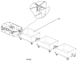
- a tugger pin may be mounted on the top plate of the monolithic chassis to attach at least one cart.
- FIGS. 1 through 6F Reference numerals of one or more components of an autonomous mobile robot (AMR) as depicted in the FIGS. 1 through 6F are provided below for ease of description: S.NO NAME OF COMPONENT REFERENCE NUMERALS 1 Autonomous Mobile Robot (AMR) 100 2 Top plate 102 3 Top plate cover 102A 4 Short length standoffs 104A-N 5 Long standoffs 106A-N 6 set of side plates 108A-B 7 a front and a rear cover 110A-B 8 an emergency switch 112A-B 9 LED covers 114A-B 10 Display unit 116 11 a tugger pin 118 12 Interface cover 120 13 LIDAR sensor 122 14 IR sensors 124A-N 15 Connecting plates 126A-B 16 Chassis 128 17 Drive wheels 130A-B 18 Battery sliding block 132A-B 19 Swivel wheel 134A-D 20 Wheel mount 136 21 Battery sub-assembly 138A-B 22 Front side counterweights 140 23 Rear side Counterweights 142
- FIG. 1A-1D illustrates an autonomous mobile robot (AMR) 100 with a single modular platform to perform plurality of tasks according to embodiments of the present disclosure.
- the mobile platform corresponds to the autonomous mobile robot (AMR) 100 which is designed to be modular and compact in order to perform plurality of tasks in one or more workspace environment.
- the chassis 128 is supported with four swivel wheels 134A-D and two motorized drive wheels 130A-B.
- the drive wheels 130A-B with a wheel mount 136 forming the drive wheel assembly 144 is isolated from the chassis 128 by means of the suspension unit.
- the interface cover 120 is configured to mount any communication ports or connecting paths for one or more base unit (e.g., the AMR 100) to plurality of handling units (e.g. tugger unit, cobot mounting unit, a lift and index table unit as shown FIG. 6A- 6F ).
- the AMR 100 includes the suspension unit in between the drive wheel assembly 144 and the chassis 128 which helps the AMR 100 to move on the ground providing damping for the platform.
- the AMR 100 is capable to operate on own program of automatic navigation system (e.g., SLAM - Simultaneous localization and Mapping) through various obstacles.
- the top plate 102 is resting on the chassis 128 and supported/located by the long stand offs 106A-N.
- the four swivel wheels 134A-D are connected at four corners of the chassis 128 allowing the AMR 100 to move freely on ground.
- the AMR 100 include the pair of motorized drive wheels 130A-B mounted on the wheel mount 136 is coupled underneath the chassis 128 forming two-wheel drive (with additional four follower wheels which are the 360 degree swivel wheels).
- the suspension unit is sandwiched in between the chassis 128 and the drive wheel housing.
- the AMR 100 may include one or more processors, communication interface device(s) or input/output (I/O) interface(s), and one or more data storage devices or memory operatively coupled to the one or more processors.
- the memory comprises a database.
- the one or more processors that are hardware processors can be implemented as one or more microprocessors, microcomputers, microcontrollers, digital signal processors, central processing units, state machines, logic circuitries, and/or any devices that manipulate signals based on operational instructions.
- the processor(s) is configured to fetch and execute computer-readable instructions stored in the memory.
- the AMR 100 can interact with variety of computing systems, such as laptop computers, notebooks, hand-held devices, workstations, mainframe computers, servers, a network cloud and the like.
- the I/O interface device(s) can include a variety of software and hardware interfaces, for example, a web interface, a graphical user interface, LCD displays and the like and can facilitate multiple communications within a wide variety of networks N/W and protocol types, including wired networks, for example, LAN, cable, etc., and wireless networks, such as WLAN, cellular, or satellite.
- the I/O interface device(s) can include one or more ports for connecting a number of devices to one another or to another server.
- the memory may include any computer-readable medium known in the art including, for example, volatile memory, such as static random access memory (SRAM) and dynamic random access memory (DRAM), and/or non-volatile memory, such as read only memory (ROM), erasable programmable ROM, flash memories, hard disks, optical disks, and magnetic tapes.
- volatile memory such as static random access memory (SRAM) and dynamic random access memory (DRAM)
- DRAM dynamic random access memory
- non-volatile memory such as read only memory (ROM), erasable programmable ROM, flash memories, hard disks, optical disks, and magnetic tapes.
- the database may store information such as but are not limited to, a plurality of parameters obtained from one or more sensors, whereas the plurality of parameters are specific to e.g., a user, a machine, a plurality of components and the like.
- the one or more sensors may be a LIDAR sensor 122, IR sensors 124A-N, an IMU sensor, a load cell, a vision sensor and the like.
- the parameters may include sensor data captured through the sensors either connected to the user and/or to the machine.
- the database stores information pertaining to inputs fed to the AMR 100 and/or outputs generated by the AMR 100 (e.g., data/output generated at each stage of the data processing), specific to the methodology described herein. More specifically, the database stores information being processed at each step of the proposed methodology.
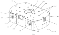
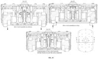
- FIG. 2A illustrates the monolithic chassis 128 of the autonomous mobile robot 100 according to embodiments of present disclosure.
- the chassis 128 corresponds to the monolithic chassis.
- the monolithic chassis 128 is designed to be symmetrical among both XX & YY central planes which are vertical and passing through centre of the AMR 100.
- the monolithic chassis (128) is symmetric about X-X and Y-Y axis comprising plurality of ribs to hold the top plate (102) and the four swivel wheels (134A-D) are coupled at four corners.
- the chassis 128 comparatively being heaviest part of the AMR 100 brings in stability to the AMR 100 under one or more applications conditions.
- the chassis 128 also houses one or more heavier components such as a battery 226, the top plate 102, plurality of standoffs, plurality of sensors and other electrical and electronics parts.
- the chassis 128 rests on the four swivel wheels 134A-D.
- the swivel wheels 134A-D provides support to the top plate 102 and associated components on top which also are very heavy.
- the chassis 128 also houses other end of elements of a suspension system i.e. the drive wheel assembly 144.
- the chassis 128 further include a provision to accommodate counterweights at bottom, counterweights can be added to balance the AMR 100 depending on one or more applications.
- the chassis 128 of the AMR 100 also made with plurality of circular cutouts at each side (widthwise) for air circulations provided extra mounting holes 210A-N around cutout to mount one or more cooling fans.
- the one or more cooling fans are used to cool electrical components and the drive wheels 130A-B.
- the cooling fan is configured to remove heat generated by electrical components in the AMR 100.
- there are a plurality of ribs 214A-N (e.g., six ribs and equal number at each side) provided from top of the chassis 128 and supports the top plate 102.
- a plurality of ribs 212A-D strengthen the chassis 128 by providing rigidity.
- each corner includes a machined surface 216 for fixing a battery sliding block 132A-B.
- the autonomous mobile robot (AMR) 100 includes the top plate 102 which holds different short length standoffs on which the different material handling units like robot/cobot mounting unit, lift and indexing table unit to carry racks, tugger unit etc., get mounted on.
- load from the different material handling units acts on the standoff then the load is configured to transfer to the top plate 102 to the chassis 128.
- the top plate 102 is mounted on the chassis 128 and located by long standoffs 106A-N whereas these stand offs also help to transfer the load directly from the top plate 102 to the chassis 128.
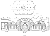
- FIG. 2B illustrates utilization of plurality of standoffs of the autonomous mobile robot (AMR) 100 according to embodiments of present disclosure.
- the AMR 100 shown in FIG. 2B which highlights standoffs used for mounting Robot/ cobot option 220A-C, standoffs used for mounting Automated tugger unit 222A-B, standoffs used for mounting Lift and indexing unit, an object identification unit & conveyor bed unit 224.
- the plurality of standoffs are integrated on top of the top plate 102.
- the top plate is sandwiched between the plurality of standoffs and the monolithic chassis (128).
- a load is transferred from the plurality of material handling units through the plurality of standoffs and the top plate (102) to the monolithic chassis (128), such a way that the top plate 102 deflection is minimal.
- the plurality of stand offs are placed in such a way that the load distribution due to additional options is transferred uniformly on to the chassis 128.
- the top plate 102 also includes a circular opening at the center and covered by a small cover to protect the IMU sensor unit and also to mount or connect one or more interfacing connectors to the one or more material handling units.
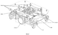
- the autonomous mobile robot (AMR) 100 includes the drive wheel assembly 144 according to embodiments of present disclosure.
- the wheel mount 136 with the two drive wheels 130A-B in center of the AMR 100 and six shafts coupled at the one end of the wheel mount 136 which forms the drive wheel assembly 144.
- the shafts are mounted on the wheel mount 136 with hexagonal bolts from the bottom side, and at the other end two center shafts receives the coil springs 308A-B and embossed in spring enclosure 306A-B, whereas remaining four shafts freely slide in the linear bearings 302A-D as the suspension unit starts actuating.
- the autonomous mobile robot includes the suspension unit according to embodiments of present disclosure.
- the suspension unit consists of the four linear bearings 302A-D and two coil springs 308A-B with the spring enclosures 306A-B and the shaft stopper 304A-B. Both the linear bearings 302A-D and spring with enclosure is supported by six shafts from the wheel mount 136. In an embodiment, arrangement is made symmetrical.
- a suspension sub assembly makes the entire drive wheel assembly 144 to move up and down in a vertical direction to ensure that the drive wheels 130A-B always be touching ground while traversing through small inclinations, bumps, ramps etc.
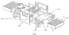
- FIG. 2C illustrates the battery housing unit of the autonomous mobile robot (AMR) 100 according to embodiments of present disclosure.
- the battery housing unit consists of two battery sliding blocks 132A-B, two connecting plates 126A-B and two batteries with battery holding tray.
- the two battery sliding blocks 132A-B are fastened on the chassis 128.
- the two blocks are further connected by the two connecting plates 126 A-B and configure the chassis 128 rigid by connecting itself in between the two left out regions of chassis cutouts.
- the monolithic chassis (128) is rigid by connecting the two side plates and connecting plates (126A-B) at front and rear side.
- the connecting plates 126A-B there provided a small space in which a battery tray with the battery can slide forward and backward by just unthreading one or more hex bolts 314 used to connect the plates.
- the connecting plates 126A-B is provided with holes for mounting the electric and electronic components.
- the autonomous mobile robot (AMR) 100 includes the set of side plates 108A-B according to embodiments of present disclosure.
- the set of side plates 108A-B connects the chassis 128 on either sides to strengthen the chassis 128.
- a plurality of pins 228A-B on the set of side plates 108A-B to the chassis 128 takes the load and prevents from deflection of the chassis 128.
- the set of side plates 108A-B improves aesthetics and holds a sheet metal outer cover as well.
- one of the set of side plate 108A-B holds a case for a display unit 116 (a HMI display).
- the autonomous mobile robot (AMR) 100 further includes the tugger pin 118 according to embodiments of present disclosure.
- the top plate 102 includes a hole at the rear end where the tugger pin 118 sits in.
- the tugger pin 118 is fixed using the hex nut 314 from the top of the top plate 102 and helps in manual tugging.
- the tugger pin 118 is made up of high strength steel to take the load so that should not fail during the operation.
- the autonomous mobile robot (AMR) 100 further includes the front and rear cover 110A-B according to embodiments of present disclosure.
- the AMR 100 includes two sheet metal curved covers one is placed at the front side and another one is placed at rear side of the AMR 100. The two covers are connected between the top plate 102 and to the chassis 128 at the bottom.
- the front cover 110A comprises enough opening space for the LIDAR sensor 122 to sense the presence of obstacle in front of the AMR 100.
- the cover also includes the cutouts for IR/ultrasonic sensor 124A-N placed at bottom.
- the rear cover 110B includes a special cutout for the tugger pin 118 and charging port of the AMR 100.
- the autonomous mobile robot (AMR) 100 further includes the top plate cover 102A that is screwed on the main top plate, which can be easily removed to access the wiring from an AMR base to the material handling units.
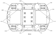
- FIG. 2D illustrates a positioning of counterweights in the autonomous mobile robot (AMR) 100 according to embodiments of the present disclosure.
- the AMR 100 in which the chassis 128 includes four positions intentionally made for counterweights placements or counterweights mounting arrangement in order to counterbalance the AMR 100.
- adding the counterweights at the bottom of the AMR 100 purely depends on application and position of the material handling unit.
- four different counterbalance weight position can be used independently or collectively for different material handling apparatus as per requirements.
- design is made adaptable for other robots with higher payloads by adding counterweights.
- the counter weights needs to be added based on at least one of following conditions: (i) If the robot/cobot is mounting on the front side of the AMR 100 then the counter weight needs to be added at the rear side of the AMR 100, (ii) During manual tugging of the train of the carts, counter weight needs to be added at the front side of the AMR 100, (iii) For automated tugging unit the counter weights needs to be added at the front side of the AMR 100, (iv) For lift and indexing table unit the counter weights may/may not be added at the either side of the AMR 100 depending on the application load characteristics, since the lift and indexing table unit is mounted at the center of the AMR 100, and (v) For robot/cobot mounting unit the counter weight needs to be added at the rear side of the AMR 100.
- a table 1 which refers to adding of the counterweight to balance the AMR 100: Table 1 S.No Material Handling units Position of material handling units (On TOP of Base vehicle) Counter weight Position of counterweights (At Bottom of Base vehicle) Payload 1 Cobot mounting Front side of the AMR Required Rear side of the AMR Yes Center of the AMR Required Both Front & rear side of the AMR Yes Rear side of the AMR Required Front side of the AMR Yes 2 Tugging (Automatic or Manual) N.A Required Front side of the AMR Yes 3 Lift and Indexing Center of the AMR Not required N.A Yes 4 Transfer conveyor Center of the AMR Required Both Front & rear side of the AMR Yes
- FIG. 3A-3D illustrates a suspension unit of the autonomous mobile robot (AMR) 100 according to embodiments of present disclosure.
- the suspension unit forms a mono-suspension unit for the drive wheels 130A-B.
- the mono-suspension unit isolates the chassis 128 from the drive wheel assembly 144.
- the wheel mount 136 with the two drive wheels 130A-B in center of the vehicle and six shafts coupled at the one end of wheel mount forms the drive wheel assembly 144.
- the suspension unit includes two spring enclosures 306A-B, two suspension shafts 312A-B, two suspension stroke restrictor 316 and two coil springs 308A-B.
- the shafts are connected to the wheel mount 136 (e.g., whereas the wheel mount 136 is rigidly connected to the drive wheels 130A-B forming the drive wheel assembly 144) and the spring enclosure 306A-B is rigidly connected to the chassis 128.
- the coils springs 308A-B is placed and compressed in between the spring enclosure 306A-B from the chassis 128 and the shafts from the wheel mount 136. Since the coil springs 308A-B is now placed in between two rigid links (i.e. the suspension shaft 312A-B and the spring enclosure 306A-B) and in compressed condition creates damping action of the AMR's platform while moving on uneven surface of the ground.
- a spring behavior is such that, can push the drive wheels 130A-B towards the ground (always ensuring the positive contact between the ground and the drive wheel) and also provides sufficient force to maintain required driving torque while moving on horizontal as well as when there is upward or downward slope (ramp).
- features which also holds the chassis 128 with a top unit of the AMR 100 and ensures that should not come out from the suspension system due to spring force.
- the suspension unit is supported by the four linear bearings 302A-D mounted on the base frame allowing the sliding contact for four another shafts (placed axially with the bearing axis) from the wheel mount 136.
- the AMR 100 includes parallel suspension through which both the drive wheels move up and down simultaneously whereas width from end of drive wheel to drive wheel is very compact & the values are not changed.
- the configuration makes the AMR 100 very compact for working in narrow aisles, and for the same vehicle with individual pivoted suspension, the system cannot be made as compact.
- individual pivoted mechanism makes arc movement of wheels which cause more width of vehicle.
- there are three position in the current suspension system actuates.
- emergency module is interfaced directly to the motor drive controller, any safety breach on the laser defined boundary are taken as emergency command and the robot starts.
- Collision avoidance is a second level of laser breach defined in software, in which any obstacle comes in that range of zone, the robot slows down and try to avoid by re-routing the AMR movement, this enables the robot to work in a collaborative environment.
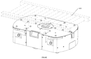
- FIG. 6D is an exemplary view illustrating a Lift and Indexing table unit 608 mounted on the platform of the AMR 100 by using the short length standoffs according to embodiments of the present disclosure.
- the Lift and Indexing table unit 608 through which the AMR 100 can transfer the different racks from one place to another place in the warehouses.
- whole unit can be mount using the center set of short length stand offs of the AMR.
- FIG. 6E is an exemplary view illustrating the AMR 100 mounted with a conveyor bed 610 according to embodiments of the present disclosure.
- small motorized roller conveyor can be fixed on to the top of the AMR 100.
- the AMR 100 mounted with the conveyor bed 610 e.g., Transfer conveyor
- the AMR 100 mounted with the conveyor bed 610 can move from one place to another place and able to receive the objects from main roller/belt conveyor and delivers to another place and vice versa.
- the AMR 100 is used only for guidance/transport and roller conveyor is used as receiver and transmitter.
- FIG. 6F is an exemplary view illustrating the object identification unit 612 required to scan and count number of parts/objects being processed according to embodiments of the present disclosure.
- the AMR 100 with scanner can be used for this application, whereas the object identification unit 612 is fixed on to the top of the AMR 100 on certain standoffs.
- the objective is to design a common mobile platform that can perform various tasks without consuming much room of the industry workspace that is being compact.
- the embodiments of the present disclosure make use of a single modular platform for more than a particular application (e.g., Pick and place, lift and transport, tugging) additional flexibility are achieved.
- the single modular platform drives down cost of manufacturing substantially since now smaller of part types to handle in order to attend the variety of applications as well as volumes.
- a load carrying capacity of the mobile platform is constrained by parameters like drive wheel power, strength of the chassis, working area and load capacity of wheels.
- the design challenge is the optimization for rise in vehicle weight for balancing and drop in vehicle weight for increasing the load carrying.
- the set of side plates are connected to the chassis to make the chassis very rigid and also to improve the aesthetic look of the AMR and also to hide the drive wheels from exposing to outside.
- the single modular platform in which one or more swivel wheels are selected to obtain compactness for complete 360-degree rotation without compromising on the load carrying capacity.
- the chassis is designed to be structurally strong with light weight material e.g., Aluminum, grade being high strength alloy. A safety factor is applied to wheel capacity and designs. After all these considerations, the required load carrying capacity of the vehicle is achieved.
- Major parts of the AMR were made up of light weight material like aluminum to reduce weight.
- Two main casting parts of the AMR i.e. chassis and wheel mount is made up of aluminum to provide the optimum weight which are the major contribution to the entire AMRs weight.
- total weight optimization of the AMR is achieved and at the same time number of parts used to form the chassis is reduced to one as name indicates "Monolithic".
- Cost reduction is a main factor to be achieved by optimizing the overall vehicle weight and reducing the total parts count and without affecting the operable load capacity and the modularization functionality of the AMR.
- the chassis includes an extra mounting holes at the bottom to add the counterweights to counterbalance the AMR if required in any of the options (material handling units) mounted on the AMR.
Landscapes
- Engineering & Computer Science (AREA)
- Mechanical Engineering (AREA)
- Chemical & Material Sciences (AREA)
- Combustion & Propulsion (AREA)
- Transportation (AREA)
- Robotics (AREA)
- Manipulator (AREA)
Claims (13)
- Robot mobile autonome (AMR) (100) avec une plate-forme modulaire unique pour monter une pluralité d'unités de manutention de matériaux, comprenant :un châssis monolithique (128) ;une plaque supérieure (102) comprenant une pluralité d'entretoises pour monter au moins une unité de manutention de matériaux ;dans lequel la pluralité d'entretoises est intégrée sur le dessus de la plaque supérieure (102), dans lequel la pluralité d'entretoises relie la plaque supérieure (102) et le châssis monolithique (128) pour fournir une zone de transfert de charge pour la plaque supérieure (102) de sorte que la charge est transférée de la pluralité d'unités de manutention de matériaux à travers la pluralité d'entretoises vers la plaque supérieure (102) puis vers le châssis monolithique (128), dans lequel la liaison de la pluralité d'entretoises avec la plaque supérieure (102) et le châssis monolithique (128) empêche la déflexion de la plaque supérieure (102), et dans lequel la pluralité d'entretoises agit comme des points de positionnement pour la plaque supérieure (102) ;des roues motrices (130A-B) couplées à un support de roue (136) comme une unité unique pour former un ensemble de roues motrices (144) ;une unité de suspension couplée entre le châssis monolithique (128) et l'ensemble de roues motrices (144), dans lequel l'unité de suspension comprend (a) des logements de ressort (306A-B), (b) des axes de suspension (312A-B), et (c) des ressorts hélicoïdaux (308A-B) agencés symétriquement, dans lequel les axes de suspension (312A-B) sont reliés au support de roue (136), dans lequel le support de roue (136) est relié rigidement aux roues motrices (130A-B), et les logements de ressort (306A-B) sont reliées rigidement au châssis monolithique (128), et dans lequel l'unité de suspension est supportée par une pluralité de paliers linéaires (302A-D) qui permet aux roues motrices (130A-B) de se déplacer verticalement ensemble en une seule unité, et dans lequel les roues motrices (130A-B) touchent le sol pour produire un couple d'entraînement, et quatre roues pivotantes (134A-D) étant fixés aux quatre coins du châssis monolithique (128) permettant à l'AMR (100) de se déplacer librement sur le sol ; etun ensemble de plaques latérales (108A-B) reliées au châssis monolithique (128) de chaque côté de l'AMR (100).
- AMR (100) selon la revendication 1, dans lequel la pluralité d'entretoises sont variées en longueur.
- AMR (100) selon la revendication 1, dans lequel un moulage monolithique du châssis monolithique (128) agit comme cadre de base de l'AMR (100).
- AMR (100) selon la revendication 1, dans lequel le châssis monolithique (128) comprend une pluralité de découpes circulaires de chaque côté de trous de fixation supplémentaires (210AN) pour monter une pluralité de ventilateurs de refroidissement, dans lequel la pluralité de ventilateurs de refroidissement assurent une circulation d'air pour refroidir des composants électriques et les roues motrices (130A-B), dans lequel le châssis monolithique (128) est conçu pour être symétrique selon les plans centraux XX et YY qui sont verticaux et passent par le centre de l'AMR (100), dans lequel le châssis monolithique (128) comprend en outre une pluralité de nervures (214A-N) pour maintenir la plaque supérieure (102), dans lequel le châssis monolithique (128) est rigidifié par la connexion de l'ensemble de plaques latérales (108A-B) et des plaques de connexion (126A-B) respectivement à l'avant et à l'arrière, dans lequel une pluralité de nervures (212A-D) est configurée pour renforcer les quatre coins du châssis monolithique (128).
- AMR (100) selon la revendication 1, dans lequel les roues motrices (130A-B) sont placées au centre de l'AMR (100) pour contrôler au moins un mouvement de l'AMR (100) parmi : (i) une avancée, (ii) une marche arrière, (iii) un mouvement de rotation, (iv) un mouvement de pivotement, et (v) un mouvement de freinage.
- AMR (100) selon la revendication 1, dans lequel un contrepoids est ajouté au bas de l'AMR (100).
- AMR (100) selon la revendication 1, dans lequel une pluralité d'axes sont montées sur le support de roue (136) avec une pluralité de fixations depuis le dessous, et dans lequel certains des axes reçoivent les ressorts hélicoïdaux (308A-B) et sont intégrés dans les logements de ressort (306A-B), dans lequel les aces restants coulissent librement dans la pluralité de paliers linéaires (302A-D) si la suspension est activée.
- AMR (100) selon la revendication 1, dans lequel les ressorts hélicoïdaux (308A-B) sont placés entre deux liens rigides, dans lequel les deux liens rigides font référence à l'axe de suspension (312A-B) et aux logements de ressort (306A-B), ce qui crée un effet d'amortissement de l'AMR (100).
- AMR (100) selon la revendication 1, dans lequel au moins l'un parmi : un robot, un cobot est monté sur la plate-forme modulaire de l'AMR (100) pour saisir et déplacer au moins un objet d'un emplacement à un autre emplacement.
- AMR (100) selon la revendication 1, dans lequel une cheville d'attelage (118) est montée sur la plaque supérieure (102) du châssis monolithique (128) pour attacher au moins un chariot, et dans lequel une unité de remorquage automatique (606) est montée à travers la pluralité d'entretoises sur la plaque supérieure (102) pour attacher automatiquement l'au moins un chariot.
- AMR (100) selon la revendication 1, dans lequel une unité de levage et de table d'indexation (608) est montée à travers la pluralité d'entretoises de l'AMR (100) pour transférer une pluralité de racks d'un emplacement à un autre emplacement.
- AMR (100) selon la revendication 1, dans lequel un convoyeur de transfert (610) est monté à travers la pluralité d'entretoises de l'AMR (100) pour livrer une pluralité d'objets d'un emplacement à un autre emplacement.
- AMR (100) selon la revendication 1, dans lequel une unité d'identification d'objet (612) est montée à travers la pluralité d'entretoises de l'AMR (100).
Applications Claiming Priority (2)
| Application Number | Priority Date | Filing Date | Title |
|---|---|---|---|
| IN201921031019 | 2019-07-31 | ||
| PCT/IB2020/056961 WO2021019383A1 (fr) | 2019-07-31 | 2020-07-23 | Robot mobile autonome à plateforme modulaire unique |
Publications (3)
| Publication Number | Publication Date |
|---|---|
| EP4003660A1 EP4003660A1 (fr) | 2022-06-01 |
| EP4003660C0 EP4003660C0 (fr) | 2025-06-25 |
| EP4003660B1 true EP4003660B1 (fr) | 2025-06-25 |
Family
ID=72266597
Family Applications (1)
| Application Number | Title | Priority Date | Filing Date |
|---|---|---|---|
| EP20764146.5A Active EP4003660B1 (fr) | 2019-07-31 | 2020-07-23 | Robot mobile autonome à plateforme modulaire unique |
Country Status (3)
| Country | Link |
|---|---|
| US (1) | US12128554B2 (fr) |
| EP (1) | EP4003660B1 (fr) |
| WO (1) | WO2021019383A1 (fr) |
Families Citing this family (24)
| Publication number | Priority date | Publication date | Assignee | Title |
|---|---|---|---|---|
| FI3908502T3 (fi) | 2019-01-11 | 2025-07-22 | Duerr Systems Ag | Kuljetuslaite, käsittelylaitos, menettelytapa esineiden kuljettamista ja/tai käsittelyä varten |
| EP3800113B1 (fr) * | 2019-10-01 | 2024-03-06 | Mobile Industrial Robots A/S | Robot mobile à poids de traction réglables |
| CN112829854A (zh) * | 2021-02-08 | 2021-05-25 | 深圳优艾智合机器人科技有限公司 | 牵引机器人和牵引设备 |
| DE102021106584B4 (de) * | 2021-03-18 | 2024-02-22 | Sick Ag | System mit mindestens einem Anlagesystem mit mindestens mehreren Anlageteilen |
| CN113212601B (zh) * | 2021-04-13 | 2025-01-24 | 深圳墨影科技有限公司 | 模块化agv |
| US12162681B2 (en) | 2021-05-19 | 2024-12-10 | Gpcp Ip Holdings Llc | Vehicle suspension system, conveyor system, and autonomous vehicles incorporating the same |
| DE102021114824A1 (de) * | 2021-06-09 | 2022-12-15 | Saurer Technologies GmbH & Co. KG | Transportfahrzeug für eine Textilfabrik |
| USD1065755S1 (en) * | 2021-06-22 | 2025-03-04 | Vmi Holland B.V. | Transport plate |
| US11724878B2 (en) | 2021-07-06 | 2023-08-15 | Intelligrated Headquarters, Llc | Modular vertical lift system |
| CN113581110B (zh) * | 2021-09-01 | 2023-03-24 | 蓝莓极客(武汉)智能科技有限公司 | 一种工业运输机器人碰撞防护装置 |
| CN113859159B (zh) * | 2021-10-28 | 2023-09-01 | 英利新能源(宁夏)有限公司 | 一种工业运输机器人碰撞防护装置及机器人用抬升装置 |
| US12240550B2 (en) * | 2021-11-17 | 2025-03-04 | Locus Robotics Corp. | Mobile robot having a removable wheel-drive assembly |
| CA3184052A1 (fr) * | 2021-12-17 | 2023-06-17 | Moyer Diebel Ltd. | Lave-verres sur demande et methode d'exploitation |
| WO2023244171A1 (fr) * | 2022-06-13 | 2023-12-21 | Globotix Pte. Ltd. | Robot modulaire autonome et procédés associés |
| JP7816222B2 (ja) * | 2023-03-06 | 2026-02-18 | 株式会社ダイフク | 物品搬送車 |
| CN116639448A (zh) * | 2023-05-29 | 2023-08-25 | 福建钰融科技有限公司 | 一种光刻剥离废液制品存储装置 |
| CN116551716A (zh) * | 2023-06-12 | 2023-08-08 | 广东爱吉尔机器人科技有限公司 | 一种高柔性移动复合机器人作业机组 |
| CN116853385A (zh) * | 2023-06-19 | 2023-10-10 | 柳州赛克科技发展有限公司 | 一种agv车体及其路面适应调节方法 |
| CN121620485A (zh) * | 2023-08-03 | 2026-03-06 | 英特诺控股公司 | 具有输送轨道的自主移动机器人 |
| WO2025048843A1 (fr) * | 2023-08-29 | 2025-03-06 | Jin Kim Yi | Robot de ramassage et de transport autonome |
| CN117184276A (zh) * | 2023-10-16 | 2023-12-08 | 本溪钢铁(集团)信息自动化有限责任公司 | 具有物品智能监测机构的冶金用搬运系统及其工作方法 |
| WO2025083073A1 (fr) * | 2023-10-16 | 2025-04-24 | Robotique Occitane - Rob'occ | Robot autonome compact à charge bidirectionnelle et accès de maintenance modulaire |
| CN221455922U (zh) * | 2023-12-01 | 2024-08-02 | 杭州海康机器人股份有限公司 | 一种机器人车架及移动机器人 |
| CN118358672B (zh) * | 2024-05-31 | 2025-09-12 | 安徽神通物联网科技集团有限公司 | 一种无车承运调度机器人 |
Family Cites Families (17)
| Publication number | Priority date | Publication date | Assignee | Title |
|---|---|---|---|---|
| SE0004465D0 (sv) | 2000-12-04 | 2000-12-04 | Abb Ab | Robot system |
| DK1587725T3 (en) | 2002-08-30 | 2014-03-17 | Aethon Inc | Trolley-pulling robot vehicle |
| US7991505B2 (en) | 2003-08-29 | 2011-08-02 | Casepick Systems, Llc | Materials-handling system using autonomous transfer and transport vehicles |
| FR2916152B1 (fr) * | 2007-05-14 | 2010-03-05 | Robosoft | Robot polyvalent |
| DE102013106640B8 (de) | 2013-06-25 | 2015-03-05 | Motum | Lager- und Kommissioniersystem zum Kommissionieren mit autonom verfahrbaren Regalbediengeräten |
| MX364080B (es) | 2013-09-09 | 2019-04-11 | Dematic Corp | Recolección móvil autónoma. |
| DK178498B1 (en) | 2015-04-13 | 2016-04-18 | Mobile Ind Robots Aps | ROBOT-BASED VEHICLE TO TOUGH A CAR |
| US10124359B2 (en) * | 2015-06-17 | 2018-11-13 | Integrated Construction Enterprises, Inc. | Autonomous painting systems and related methods |
| EP3192616B1 (fr) | 2016-01-14 | 2024-09-25 | Jungheinrich AG | Robot pour ramasser et transporter des objets et procédé utilisant un tel robot |
| CN105946451B (zh) * | 2016-05-06 | 2019-10-25 | 中国科学院宁波材料技术与工程研究所 | 全向移动平台及其舵轮和驱动轮 |
| US10434924B2 (en) * | 2016-09-09 | 2019-10-08 | Dematic Corp. | Free ranging automated guided vehicle and operational system |
| US11142399B2 (en) | 2016-10-06 | 2021-10-12 | Doerfer Corporation | Automated warehouse fulfillment system and method of operation |
| KR101973245B1 (ko) * | 2016-12-22 | 2019-04-26 | 한채진 | 무인 자동운반대차 |
| CN107323194A (zh) * | 2017-08-16 | 2017-11-07 | 苏州索亚机器人技术有限公司 | 一种加装悬挂减震机构的移动机器人 |
| CN109015587A (zh) * | 2018-05-28 | 2018-12-18 | 上海锐铎自动化有限公司 | 一种设有手爪库的agv车 |
| US11199853B1 (en) * | 2018-07-11 | 2021-12-14 | AI Incorporated | Versatile mobile platform |
| US11633848B2 (en) * | 2019-07-31 | 2023-04-25 | X Development Llc | Independent pan of coaxial robotic arm and perception housing |
-
2020
- 2020-07-23 WO PCT/IB2020/056961 patent/WO2021019383A1/fr not_active Ceased
- 2020-07-23 US US17/631,276 patent/US12128554B2/en active Active
- 2020-07-23 EP EP20764146.5A patent/EP4003660B1/fr active Active
Also Published As
| Publication number | Publication date |
|---|---|
| US20220258327A1 (en) | 2022-08-18 |
| EP4003660A1 (fr) | 2022-06-01 |
| US12128554B2 (en) | 2024-10-29 |
| WO2021019383A1 (fr) | 2021-02-04 |
| EP4003660C0 (fr) | 2025-06-25 |
Similar Documents
| Publication | Publication Date | Title |
|---|---|---|
| EP4003660B1 (fr) | Robot mobile autonome à plateforme modulaire unique | |
| EP3660619B1 (fr) | Combinaisons de robots deux roues. | |
| KR102889717B1 (ko) | 무인 지상 기반 운송 차량 및 물품 운송 방법 | |
| EP3944930B1 (fr) | Véhicule de maintenance d'hygiène au sol sans pilote et méthode d'amélioration des conditions d'hygiène | |
| KR102539465B1 (ko) | 서스펜션 모듈을 포함하는 이동 로봇 | |
| US9731641B2 (en) | Tilting platform for stability control | |
| EP3347290B1 (fr) | Véhicule guidé automatisé avec bras robotique de prélèvement par lots | |
| CN117355392A (zh) | 集成移动机械手机器人 | |
| US9890025B2 (en) | Mechanical tipping assembly for mobile drive unit of inventory system | |
| CN111771176A (zh) | 运输设备的控制器和方法 | |
| US12280672B2 (en) | Autonomous mobile robot for outdoor applications | |
| CN118574709A (zh) | 用于致动机器人操纵器的系统和方法 | |
| US20220009712A1 (en) | Assembly Material Logistics System and Methods | |
| JP7668875B2 (ja) | 倉庫内でペイロードを保管及び回収するための移動台車 | |
| US20250353681A1 (en) | Transport Vehicle With Lift And Rotate Functionality | |
| CN223644872U (zh) | 输送机器人 | |
| US20250375875A1 (en) | Modular robotic pod system | |
| CN116788734A (zh) | 仓储系统 | |
| Grasz et al. | Novel transport-vehicle design for moving optic modules in the National Ignition Facility |
Legal Events
| Date | Code | Title | Description |
|---|---|---|---|
| STAA | Information on the status of an ep patent application or granted ep patent |
Free format text: STATUS: UNKNOWN |
|
| STAA | Information on the status of an ep patent application or granted ep patent |
Free format text: STATUS: THE INTERNATIONAL PUBLICATION HAS BEEN MADE |
|
| PUAI | Public reference made under article 153(3) epc to a published international application that has entered the european phase |
Free format text: ORIGINAL CODE: 0009012 |
|
| STAA | Information on the status of an ep patent application or granted ep patent |
Free format text: STATUS: REQUEST FOR EXAMINATION WAS MADE |
|
| 17P | Request for examination filed |
Effective date: 20220128 |
|
| AK | Designated contracting states |
Kind code of ref document: A1 Designated state(s): AL AT BE BG CH CY CZ DE DK EE ES FI FR GB GR HR HU IE IS IT LI LT LU LV MC MK MT NL NO PL PT RO RS SE SI SK SM TR |
|
| DAV | Request for validation of the european patent (deleted) | ||
| DAX | Request for extension of the european patent (deleted) | ||
| STAA | Information on the status of an ep patent application or granted ep patent |
Free format text: STATUS: EXAMINATION IS IN PROGRESS |
|
| 17Q | First examination report despatched |
Effective date: 20240820 |
|
| REG | Reference to a national code |
Ref country code: DE Free format text: PREVIOUS MAIN CLASS: B25J0005000000 Ref country code: DE Ref legal event code: R079 Ref document number: 602020053355 Country of ref document: DE Free format text: PREVIOUS MAIN CLASS: B25J0005000000 Ipc: B62D0061100000 |
|
| GRAP | Despatch of communication of intention to grant a patent |
Free format text: ORIGINAL CODE: EPIDOSNIGR1 |
|
| STAA | Information on the status of an ep patent application or granted ep patent |
Free format text: STATUS: GRANT OF PATENT IS INTENDED |
|
| RIC1 | Information provided on ipc code assigned before grant |
Ipc: B25J 5/00 20060101ALI20250117BHEP Ipc: B65G 1/137 20060101ALI20250117BHEP Ipc: B62D 63/02 20060101ALI20250117BHEP Ipc: B62D 61/10 20060101AFI20250117BHEP |
|
| INTG | Intention to grant announced |
Effective date: 20250214 |
|
| GRAS | Grant fee paid |
Free format text: ORIGINAL CODE: EPIDOSNIGR3 |
|
| GRAA | (expected) grant |
Free format text: ORIGINAL CODE: 0009210 |
|
| STAA | Information on the status of an ep patent application or granted ep patent |
Free format text: STATUS: THE PATENT HAS BEEN GRANTED |
|
| AK | Designated contracting states |
Kind code of ref document: B1 Designated state(s): AL AT BE BG CH CY CZ DE DK EE ES FI FR GB GR HR HU IE IS IT LI LT LU LV MC MK MT NL NO PL PT RO RS SE SI SK SM TR |
|
| REG | Reference to a national code |
Ref country code: GB Ref legal event code: FG4D |
|
| REG | Reference to a national code |
Ref country code: CH Ref legal event code: EP |
|
| REG | Reference to a national code |
Ref country code: CH Ref legal event code: EP |
|
| REG | Reference to a national code |
Ref country code: IE Ref legal event code: FG4D |
|
| REG | Reference to a national code |
Ref country code: DE Ref legal event code: R096 Ref document number: 602020053355 Country of ref document: DE |
|
| U01 | Request for unitary effect filed |
Effective date: 20250625 |
|
| U07 | Unitary effect registered |
Designated state(s): AT BE BG DE DK EE FI FR IT LT LU LV MT NL PT RO SE SI Effective date: 20250702 |
|
| U20 | Renewal fee for the european patent with unitary effect paid |
Year of fee payment: 6 Effective date: 20250725 |
|
| PG25 | Lapsed in a contracting state [announced via postgrant information from national office to epo] |
Ref country code: NO Free format text: LAPSE BECAUSE OF FAILURE TO SUBMIT A TRANSLATION OF THE DESCRIPTION OR TO PAY THE FEE WITHIN THE PRESCRIBED TIME-LIMIT Effective date: 20250925 Ref country code: GR Free format text: LAPSE BECAUSE OF FAILURE TO SUBMIT A TRANSLATION OF THE DESCRIPTION OR TO PAY THE FEE WITHIN THE PRESCRIBED TIME-LIMIT Effective date: 20250926 |
|
| PGFP | Annual fee paid to national office [announced via postgrant information from national office to epo] |
Ref country code: GB Payment date: 20250722 Year of fee payment: 6 |
|
| PG25 | Lapsed in a contracting state [announced via postgrant information from national office to epo] |
Ref country code: HR Free format text: LAPSE BECAUSE OF FAILURE TO SUBMIT A TRANSLATION OF THE DESCRIPTION OR TO PAY THE FEE WITHIN THE PRESCRIBED TIME-LIMIT Effective date: 20250625 |
|
| PGFP | Annual fee paid to national office [announced via postgrant information from national office to epo] |
Ref country code: CH Payment date: 20250801 Year of fee payment: 6 |
|
| PG25 | Lapsed in a contracting state [announced via postgrant information from national office to epo] |
Ref country code: RS Free format text: LAPSE BECAUSE OF FAILURE TO SUBMIT A TRANSLATION OF THE DESCRIPTION OR TO PAY THE FEE WITHIN THE PRESCRIBED TIME-LIMIT Effective date: 20250925 |
|
| PG25 | Lapsed in a contracting state [announced via postgrant information from national office to epo] |
Ref country code: IS Free format text: LAPSE BECAUSE OF FAILURE TO SUBMIT A TRANSLATION OF THE DESCRIPTION OR TO PAY THE FEE WITHIN THE PRESCRIBED TIME-LIMIT Effective date: 20251025 |
|
| PG25 | Lapsed in a contracting state [announced via postgrant information from national office to epo] |
Ref country code: SM Free format text: LAPSE BECAUSE OF FAILURE TO SUBMIT A TRANSLATION OF THE DESCRIPTION OR TO PAY THE FEE WITHIN THE PRESCRIBED TIME-LIMIT Effective date: 20250625 |
|
| PG25 | Lapsed in a contracting state [announced via postgrant information from national office to epo] |
Ref country code: CZ Free format text: LAPSE BECAUSE OF FAILURE TO SUBMIT A TRANSLATION OF THE DESCRIPTION OR TO PAY THE FEE WITHIN THE PRESCRIBED TIME-LIMIT Effective date: 20250625 |
|
| PG25 | Lapsed in a contracting state [announced via postgrant information from national office to epo] |
Ref country code: PL Free format text: LAPSE BECAUSE OF FAILURE TO SUBMIT A TRANSLATION OF THE DESCRIPTION OR TO PAY THE FEE WITHIN THE PRESCRIBED TIME-LIMIT Effective date: 20250625 |
|
| PG25 | Lapsed in a contracting state [announced via postgrant information from national office to epo] |
Ref country code: SK Free format text: LAPSE BECAUSE OF FAILURE TO SUBMIT A TRANSLATION OF THE DESCRIPTION OR TO PAY THE FEE WITHIN THE PRESCRIBED TIME-LIMIT Effective date: 20250625 |
|
| PG25 | Lapsed in a contracting state [announced via postgrant information from national office to epo] |
Ref country code: ES Free format text: LAPSE BECAUSE OF FAILURE TO SUBMIT A TRANSLATION OF THE DESCRIPTION OR TO PAY THE FEE WITHIN THE PRESCRIBED TIME-LIMIT Effective date: 20250625 |
|
| PG25 | Lapsed in a contracting state [announced via postgrant information from national office to epo] |
Ref country code: MC Free format text: LAPSE BECAUSE OF FAILURE TO SUBMIT A TRANSLATION OF THE DESCRIPTION OR TO PAY THE FEE WITHIN THE PRESCRIBED TIME-LIMIT Effective date: 20250625 |
|
| PLBE | No opposition filed within time limit |
Free format text: ORIGINAL CODE: 0009261 |
|
| STAA | Information on the status of an ep patent application or granted ep patent |
Free format text: STATUS: NO OPPOSITION FILED WITHIN TIME LIMIT |