EP4003662B1 - Module de bras, bras de robot et robot industriel - Google Patents
Module de bras, bras de robot et robot industriel Download PDFInfo
- Publication number
- EP4003662B1 EP4003662B1 EP20747371.1A EP20747371A EP4003662B1 EP 4003662 B1 EP4003662 B1 EP 4003662B1 EP 20747371 A EP20747371 A EP 20747371A EP 4003662 B1 EP4003662 B1 EP 4003662B1
- Authority
- EP
- European Patent Office
- Prior art keywords
- arm module
- contact device
- connection side
- fluid
- connection
- Prior art date
- Legal status (The legal status is an assumption and is not a legal conclusion. Google has not performed a legal analysis and makes no representation as to the accuracy of the status listed.)
- Active
Links
Images








Classifications
-
- B—PERFORMING OPERATIONS; TRANSPORTING
- B25—HAND TOOLS; PORTABLE POWER-DRIVEN TOOLS; MANIPULATORS
- B25J—MANIPULATORS; CHAMBERS PROVIDED WITH MANIPULATION DEVICES
- B25J9/00—Program-controlled manipulators
- B25J9/08—Program-controlled manipulators characterised by modular constructions
-
- B—PERFORMING OPERATIONS; TRANSPORTING
- B25—HAND TOOLS; PORTABLE POWER-DRIVEN TOOLS; MANIPULATORS
- B25J—MANIPULATORS; CHAMBERS PROVIDED WITH MANIPULATION DEVICES
- B25J15/00—Gripping heads and other end effectors
- B25J15/04—Gripping heads and other end effectors with provision for the remote detachment or exchange of the head or parts thereof
- B25J15/0408—Connections means
- B25J15/045—Connections means having screw means
-
- B—PERFORMING OPERATIONS; TRANSPORTING
- B25—HAND TOOLS; PORTABLE POWER-DRIVEN TOOLS; MANIPULATORS
- B25J—MANIPULATORS; CHAMBERS PROVIDED WITH MANIPULATION DEVICES
- B25J17/00—Joints
-
- B—PERFORMING OPERATIONS; TRANSPORTING
- B25—HAND TOOLS; PORTABLE POWER-DRIVEN TOOLS; MANIPULATORS
- B25J—MANIPULATORS; CHAMBERS PROVIDED WITH MANIPULATION DEVICES
- B25J18/00—Arms
-
- B—PERFORMING OPERATIONS; TRANSPORTING
- B25—HAND TOOLS; PORTABLE POWER-DRIVEN TOOLS; MANIPULATORS
- B25J—MANIPULATORS; CHAMBERS PROVIDED WITH MANIPULATION DEVICES
- B25J19/00—Accessories fitted to manipulators, e.g. for monitoring, for viewing; Safety devices combined with or specially adapted for use in connection with manipulators
- B25J19/0025—Means for supplying energy to the end effector
- B25J19/0029—Means for supplying energy to the end effector arranged within the different robot elements
-
- B—PERFORMING OPERATIONS; TRANSPORTING
- B25—HAND TOOLS; PORTABLE POWER-DRIVEN TOOLS; MANIPULATORS
- B25J—MANIPULATORS; CHAMBERS PROVIDED WITH MANIPULATION DEVICES
- B25J19/00—Accessories fitted to manipulators, e.g. for monitoring, for viewing; Safety devices combined with or specially adapted for use in connection with manipulators
- B25J19/0025—Means for supplying energy to the end effector
- B25J19/0029—Means for supplying energy to the end effector arranged within the different robot elements
- B25J19/0041—Means for supplying energy to the end effector arranged within the different robot elements having rotary connection means
-
- B—PERFORMING OPERATIONS; TRANSPORTING
- B25—HAND TOOLS; PORTABLE POWER-DRIVEN TOOLS; MANIPULATORS
- B25J—MANIPULATORS; CHAMBERS PROVIDED WITH MANIPULATION DEVICES
- B25J9/00—Program-controlled manipulators
- B25J9/0009—Constructional details, e.g. manipulator supports, bases
Definitions
- the invention relates to an arm module according to patent claim 1, a robot arm according to patent claim 13 and an industrial robot according to patent claim 15.
- the technical discipline of automation technology has the task of making machines incl.
- a degree of automation in an automation system is all the higher, the more independent a respective machine in a plant and/or a relevant plant is or are from human intervention.
- the goals of automation technology are to relieve people of dangerous, strenuous and/or monotonous activities, to improve the quality of the goods produced by the technical system, to increase the efficiency of the system and to reduce costs through the system.
- the degree of automation of an existing or a new system can be significantly increased in comparison with the prior art.
- An automation system has appropriate components for communication, which usually communicate with one another in what is known as a local area network, which is a spatially limited network in which the various network components are coupled to one another wirelessly, optically, electrically and/or optoelectrically.
- the network components can be one or more servers and one or more workstations, so-called network elements or topologically: network nodes, which, for. B. are connected to each other via radio links, fiber optics, coaxial cable and / or twisted pair cable and can communicate via them.
- An automation communication network used in automation technology generally corresponds to a so-called fieldbus system.
- a fieldbus system is a bus system in which decentrally arranged components of a machine periphery such as input modules, output modules, drives, operating terminals, etc. are connected to control units via the fieldbus system.
- a common transmission channel is available for data transmission, e.g. B. in the form of the fieldbus or as a radio link.
- the communication between the network components within the LAN is based on network protocols.
- An industrial robot is a programmable machine for handling, assembling and/or processing workpieces.
- the industrial robot generally comprises a robot base, a robot arm with a plurality of proximal and distal arm members that can be pivoted and/or rotated relative to one another, an end effector, a local controller/regulator and, if appropriate, a global controller/regulator.
- Industrial robots are often equipped with different sensors. When programmed, the industrial robot is able to carry out a work process autonomously or to vary the execution of a task depending on information from a sensor.
- the U.S. 2018/0111275 A1 a modular robotic arm.
- the modular robotic arm has a set of modular robotic components that are connected together.
- a ring section is provided in each case to connect the modular robot components to one another. In this configuration, high forces act on the connection between the two robot components.
- the robotic manipulator arm has a first joint comprising a first end assembly having a mechanical coupling interface and an electrical interface; a second end assembly having a mechanical docking interface and an electrical interface; and a second joint.
- the second joint includes a third end assembly having a mechanical coupling interface and an electrical interface; and a fourth end assembly with a mechanical Coupling interface and an electrical interface.
- the first and fourth end assemblies are connectable at the first and fourth mechanical mating interfaces to form a first adapter between the first and second joints having an operable electrical connection between the first and fourth electrical interfaces.
- the first and second hinges are releasable at the first adapter and reconnectable at the second and third mechanical docking interfaces to form a second adapter between the first and second hinges that provides an operative electrical connection between the second and third electrical interface contains.
- the object of the invention is to provide an arm module for a robot arm that is particularly quick and easy to assemble, a robot arm that is particularly easy and flexible to assemble, and an industrial robot.
- an improved arm module can be provided in that the arm module has a first housing, a first connection side and a second connection side.
- the first connection side has a first connection plate, a first fluid contact device and a first contact device.
- the second connection side is mechanically non-rotatably connected to the first housing and has a second connection plate, the first fluid contact device and the first contact device being arranged on the first connection plate and extending parallel to a first assembly axis.
- the first connection side can be mechanically connected to a further arm module of the robot arm, with a fluid, in particular compressed air or a hydraulic fluid, being exchangeable via the first fluid contact device and an optical signal and/or an electrical signal for data transmission to the further arm module being exchangeable via the first contact device.
- an external thread is arranged circumferentially around the first assembly axis, the second connecting plate being surrounded peripherally by a fastening ring and the fastening ring having an internal thread corresponding to the external thread on an inner peripheral side.
- the mounting ring is axially fixed and rotatably connected about the second mounting axis to a first housing of the arm module, wherein at a first end toothing is arranged on the first connecting plate.
- the second connecting plate has a second spur gearing, the first spur gearing and the second spur gearing being designed to complement and/or correspond to one another.
- This configuration has the advantage that in a single assembly step for connecting the arm module to the further arm module, both a fluid connection and the data connection and additionally a mechanically resilient connection to the further arm module can be established.
- the arm module can be assembled with the other active arm module particularly quickly and easily to form a modular robot arm.
- high torques can be transmitted via the first and second face gearing, so that the arm module can be accelerated particularly quickly.
- the arm module can support a heavy load of, for example, an object to be lifted.
- the optical signal or electrical signal for data transmission can be routed on the inside of the arm module and a fluid line and/or data line can be dispensed with on the outside of the arm module. Unintentional damage to the arm module, for example by getting caught and/or snagging on the fluid line and/or data line, is thus reliably avoided.
- the arm module can be manufactured particularly quickly and automatically in large series.
- the arm module for a modular system of a modular robot can be manufactured particularly cost-effectively.
- first spur gearing and/or the second spur gearing is designed as Hirth gearing.
- first face gearing and/or the second face gearing is designed to be self-centering and automatic centering can be provided when the further arm module is installed on the first connection side.
- the second end toothing is arranged on the inside adjoining the fastening ring.
- the second end toothing can be designed to be particularly slim in the radial direction, so that overall the space required for the first and second connection sides is particularly small.
- the second spur gearing is arranged on the inside adjacent to the fastening ring.
- the first connecting plate and the first face gearing are formed in one piece and from the same material.
- the first connection side can be produced in an injection molding process in a particularly cost-effective and mechanically stable manner.
- the second connecting plate and the second end toothing are formed in one piece and from the same material.
- the second connection side can be produced in an injection molding process in a particularly cost-effective and mechanically stable manner.
- the first end toothing has at least one first tooth, the first tooth having a first indentation which extends in the axial direction along the first assembly axis, the second connection side being non-rotatably connected to the first housing by means of a third fastening means, wherein the third fastening means protrudes over the second connection plate, wherein the first indentation is formed at least in sections corresponding to the third fastening means.
- the first face toothing adjoins the first outer peripheral side in the radial direction on the inside, the first fluid contact device being arranged radially between the first power contact device and the first face toothing.
- the first power contact device is arranged in the radial direction relative to the first assembly axis between the first contact device and the first fluid contact device, with the first fluid contact device being arranged radially on the outside of the first power contact device between the first power contact device and the first outer peripheral side on the first connection plate with a fluid, in particular compressed air or a hydraulic fluid, being transmitted via the first fluid contact device, an optical signal and/or an electrical signal for data transmission via the first contact device, and electrical power for supplying the Arm module with electrical energy away is transferable.
- This configuration has the advantage that an optimally compact configuration of the first connection side can thereby be provided, via which a high fluid flow and a high electrical current can be transmitted. Due to the centered arrangement of the contact device, unrestricted rotatability of the first connection side can be ensured with a simultaneously high data transmission rate, in particular in accordance with the EtherCAT standard.
- the second connection side has a second fluid contact device designed to correspond to the first fluid contact device, a second power contact device designed to correspond to the first power contact device, and a second contact device designed to correspond to the first contact device, with the second fluid contact device, the second power contact device and the second contact device are arranged and the second fluid contact device, the second power contact device and the second contact device extend along a second assembly axis, the first fluid contact device being fluidically connected to the second fluid contact device directly or indirectly in the first housing and the first contact device being connected to the second contact device in terms of data technology for transmission of the optical and/or electrical signal directly or indirectly t are connected in the first housing, the first power contact device and the second power contact device being electrically connected to one another directly or indirectly in the first housing, the first power contact device and the second power contact device being electrically connected to one another, the fluid via the second fluid contact device the electrical power can be transmitted via the second power contact device and the optical and/or the electrical signal can be transmitted via the second contact device.
- the first fluid contact device has a plurality of first fluid contacts which are offset in the circumferential direction relative to the first assembly axis, the first fluid contacts being arranged concentrically with respect to the first assembly axis and being identical to one another, the first fluid contacts being fluidically separate from one another and/or at least are partially fluidically connected in parallel. This allows different fluids, for example, with a different pressure level or a fluid in different directions or a particularly large mass flow of the fluid can be transmitted via the first connection side.
- the second fluid contact device has at least one second fluid contact, the second fluid contact extending parallel to the second assembly axis, the first fluid contact being connected to the second fluid contact for the exchange of a fluid, the first fluid contact being a pipe receptacle and the second Fluid contact have a tube section, wherein the tube receptacle and the tube section are formed at least circumferentially corresponding to each other.
- the first connection side is designed to be particularly compact in the axial direction.
- the arm module has a pin running at a distance and parallel to the first mounting axis, the pin being electrically and mechanically connected to the first connection plate and protruding over the first connection plate, the pin being designed into a pin receptacle of the further arm module for coding and/or positioning of the arm module in relation to the further arm module and/or wherein the second connecting plate has a pin receptacle, the pin receptacle being designed to correspond to the pin and being set up to receive a pin of a further arm module. In this way, incorrect assembly can be avoided.
- the arm module is designed as an active arm module and has a drive device, with the first connection side being mounted such that it can rotate about the first assembly axis and being connected to the drive device in a torque-locking manner, with the drive device being designed to controllably reverse the first connection side to rotate the first mounting axis. Due to the embodiment of the arm module described above, the drive device can rotate the first connection side around the first mounting axis without limitation.
- the arm module is designed as a passive arm module, with the first connection plate being connected in a rotationally fixed manner to the first housing on a side of the first housing which faces away from the second connection side.
- the first connection side has a hollow shaft, the hollow shaft being torque-locked to an output side of the drive device, the hollow shaft extending through the drive device and a first axial end of the hollow shaft being non-rotatably connected to the first connection plate and a second axial end of the hollow shaft is arranged at a distance from the drive device, at least one fluid channel fluidically connected to the first fluid contact device and at least one electrical data connection connected to the first contact device being arranged in the hollow shaft.
- the arm module can be designed to be particularly compact in the radial direction relative to the assembly axis.
- An improved robot arm for an industrial robot can be provided in that the robot arm has at least a first arm module and a second arm module, the first arm module and the second arm module being designed as described above.
- the fastening ring of the first arm module is screwed onto the first connection side of the second arm module in such a way that the internal thread of the first arm module and the external thread of the first connection side of the second arm module engage with one another and the first face serration of the first connection side and the second face serration of the second connection side engage with one another.
- the first connection side of the second arm module is mechanically connected to the second connection side of the first arm module for the transmission of supporting forces and/or driving forces between the first arm module and the second arm module.
- the fluid for an end effector that can be connected to the robot arm and/or the optical signal and/or the electrical signal for data transmission and for controlling the two arm modules and/or the end effector can be exchanged via the interconnected first and second connection sides of the first arm module and second arm module .
- the internal thread can be quickly and easily screwed onto the external thread using the fastening ring, thus ensuring that the spur gears engage in one another axially.
- a particularly high torque can be exchanged between the first arm module and the second arm module.
- the robot arm can move particularly heavy loads and/or be moved particularly quickly.
- first spur gearing and the second spur gearing are formed in relation to one another in such a way that the two spur gearings are aligned centered on the first assembly axis when the first connection side is mounted on the second connection side by the two spur gearings sliding along one another.
- the second connection side has the pin receptacle, the pin receptacle for orienting and/or coding the second connection side relative to the first connection side and is arranged in the second connection plate, wherein when the first connection side and the second connection side are in the assembled state, the pin engages in the pin receptacle and preferably the first connection plate of the first connection side is electrically connected to the second connection plate to form a ground contact between the connects both arm modules. This means that no additional ground connection is required.
- a particularly advantageous industrial robot has a robot arm and a robot base as described above, the first connection side of the first arm module facing the robot base, the fluid and/or the optical signal passing over the first connection side of the second arm module and the second connection side of the first arm module and/or the electrical signal can be transmitted between the first connection side of the first arm module that faces the robot base and a second connection side of the second arm module that faces away from the robot base.
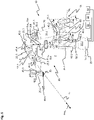
- an (automatic) machine with multiple degrees of freedom (in figure 1 e.g. six rotational degrees of freedom) for automation technology, which can perform various functions in a work environment in (limited) personal contribution by means of a pre-programmed control/regulation.
- the industrial robot 10 comprises a robot base 15, a robot arm 20 and a preferably exchangeable end effector (in figure 1 not shown), can also be described as a robot hand, with e.g. B .: a tool, a gripper, etc., which is arranged at a free end of the robot arm 20.
- the present robot arm 20 of the industrial robot 10 is in particular designed in a modular manner from a modular construction kit with a plurality of arm modules 18 .
- the arm modules 18 can, for example, be constructed as an active arm module 25 or as a passive arm module 30 or as an end effector.
- the modular system can also have other (arm and/or end) modules.
- the structure of the robot arm 20 with active arm modules 25 and passive arm modules 30 can be selected as desired and is only limited in terms of a maximum carrying capacity of the arm modules 18 .
- the active arm modules 25 are numbered, where in figure 1 is numbered from the robot base 15 towards the end effector.
- the passive arm modules 30 are also numbered for better differentiation.
- a third passive arm module 30.3 is connected to the robot base 15 at one end and to a first active arm module 25.1 at the other end.
- the first active arm module 25.1 is connected at its second end to a second active arm module 25.2.
- a first passive arm module 30.1 is arranged between the second active arm module 25.2 and a third active arm module 25.3.
- the third active arm module 25.3 is connected to a fourth active arm module 25.4 on a side remote from the first passive arm module 30.1, which is connected to a second passive arm module 30.2 on a side remote from the third active arm module 25.3.
- the second passive arm module 30.2 is connected to a fifth active arm module 25.5.
- a sixth active arm module 25.6 is arranged on the side facing away from the second passive arm module 30.2, on which the end effector is arranged on a first connection side 40.6 facing away from the fifth active arm module 25.5.
- the first connection side 40.6 of the sixth active arm module 25.6 thus forms an end effector connection side 35 to which the end effector can be connected.
- the active arm modules 25 each have a drive device, by means of which a further active arm module 25 that can be connected to it or a passive arm module 30 can be rotated about an associated axis of rotation Ra n of the active arm module 25 .
- the passive arm modules 30 do not have the drive device. So you are designed as a kind of extension part.
- the robot arm 20 also comprises a corresponding number of rotation axes Ra n .
- any number of complete revolutions of a relevant active arm module 25 of the robot arm 20 can preferably be carried out in preferably both circumferential directions Ura n of a relevant axis of rotation Ra n .
- the explanation below refers to a polar coordinate system of an active arm module 25 in each case.
- the polar coordinate system in each case has an axis of rotation Ra n pointing in general and not to a specific active arm module 25 .
- An axial direction Ara n of the active arm module 25 runs along the axis of rotation Ra n .
- a radial direction Rra n of the respective active arm module 25 runs perpendicularly outwards in relation to the respective axis of rotation Ra n .
- a circumferential direction Ura n of the respective active arm module 25 runs on a (circle -) Path about the axis of rotation Ra n of the active arm module 25.
- the general nomenclature is used to explain the construction of the active arm module 25 in general.
- the axes of rotation Ra n , the axial directions Ara n and the circumferential directions Ura n of the respective active arm module 25 are denoted according to their numbering.
- a first axis of rotation Ra 1 of the first active arm module 25.1 carries the index 1 as an index at the point of n.
- a second axis of rotation Ra 2 of the second active arm module 25.2 is correspondingly in figure 1 labeled.
- the axial directions Ara n , the radial directions Rra n and the circumferential directions Ura n of the active arm modules 25 are also designated analogously.
- the first axis of rotation Rai, the first axial direction Ara 1 and the first circumferential direction Ura 1 are drawn in.
- each coordinate system has a longitudinal axis La n .
- An axial direction Arp n of the respective passive arm module 30 runs along the longitudinal axis La n .
- a force and/or torque sensor and, if necessary, a first and/or second sensor device of an active arm module 25 is preferably assigned to a respective axis of rotation Ra n of the active arm module 25, with which a force and/or a torque can be applied to the active arm module 25 and a position of the active arm module 25 relative to the axis of rotation Ra n can be detected.
- the axis of rotation Ra n is, for example, an ideal “joint” (rotational joint, rotary joint and/or swivel joint) of the multi-part or preferably modular robot arm 20, e.g. B. opposite the robot base 15 formed.
- a force, torque and/or position sensor for monitoring forces and/or torques occurring on the robot arm 20 and/or a relative position of the arm modules 18 to one another can be provided for the respective axis of rotation Ra n . This may also be limited to a portion of the robotic arm 20 .
- a specific modular system for a robot arm 20 has at least one type of active arm module 25 configured, for example, I, J, L, or T-shaped, and preferably at least one type of, for example, I, J, L, or T -shaped passive arm module 30 on. Examples are in figure 1 the active arm modules 25 are J- or L-shaped, while the passive arm modules 30 are, for example, I-shaped.
- All arm modules 18 of the modular system for robot arms 20 are preferably designed in such a way that each of the arm modules 18 has at least two first, second, third and/or fourth connection sides 40, 45, 50, 55.
- the first to fourth connection sides 40, 45, 50, 55 of the arm modules 18 can correspond to one another and can be connected to one another.
- each active arm module 25 has a first connection side 40 and a second connection side 45 .
- Each passive arm module 30 has a third connection side 50 and a fourth connection side 55 .
- each active arm module 25 has two first connection sides 40 or two second connection sides 45 .
- each passive arm module 30 it is also possible for each passive arm module 30 to have two third connection sides 50 or two fourth connection sides 55 .
- first to fourth connection side 40, 45, 50, 55 the assignment of the first to fourth connection sides 40, 45, 50, 55 corresponds to the numbering of the active arm modules 25 or the passive arm modules 30. This is the first connection side of the first active arm module 25.1 with the reference number 40.1 in figure 1 designated.
- the first connection side 40, the second connection side 45, the third connection sides 50 and the fourth connection sides 55 are designed to correspond to one another. This means that a second connection side 45 of another active arm module 25 or a third connection side 50 of a passive arm module 30 could be connected to each first connection side 40 of an active arm module 25 . Likewise, a first connection side 40 of another active arm module 25 or a fourth connection side 55 of a passive arm module 30 could be connected to every second connection side 45 of an active arm module 25 .
- the fourth connection side 55.3 of the third passive arm module 30.3 is connected to the robot base 15.
- the robot arm 20 is connected to a (pressure) fluid 51 via the fourth connection side 55.3 of the third passive arm module 30.3, in particular with compressed air or a pressurized hydraulic fluid, which is introduced into the robot arm 20 via the fourth connection side 55.3 of the third passive arm module 30.3.
- the robot arm 20 is connected electrically to an electrical energy source 52 in terms of power and to a data network 53 in terms of data technology.
- a second connection side 45.1 of the first active arm module 25.1 is connected to a first connection side 40.2 of the second active arm module 25.2.
- the first passive arm module 30.1 is arranged between a second connection side 45.2 of the second active arm module 25.2 and a second connection side 45.3 of the third active arm module 25.3, with a fourth connection side 55.1 of the first passive arm module 30.1 being connected to the second connection side 45.2 of the second active arm module 25.2 on one End and at the other end another fourth connection side 55.1 of the first passive arm module 30.1 is connected to a second connection side 45.3 of the third active arm module 25.3.
- both connection sides of the first passive arm module 30.1 are thus exemplary as fourth connection sides 55.1 of the first passive arm module 30.1 and thus corresponding and/or complementary to the second Connection side 45.2 of the second active arm module 25.2 and the second connection side 45.3 of the third active arm module 25.3 formed.
- the second connection side 45.2 of the second active arm module 25.2 can be arranged at a distance from the second connection side 45.3 of the third active arm module 25.3 in a simple manner and a predefined design of the robot arm 20 can be implemented in a simple manner.
- An example is in figure 1 a first connection side 40.3 of the third active arm module 25.3 is connected to a second connection side 45.4 of a fourth active arm module 25.4.
- a second passive arm module 30.2 is, for example, designed differently in the modular system than the first passive arm module 30.1. In the axial direction of the second passive arm module 30.2, the second passive arm module 30.2 is shorter than the first passive arm module 30.1. Furthermore, a third connection side 50.2 of the second passive arm module 30.2 is identical to the second connection side 45.4 of the fourth active arm module 25.4 and a fourth connection side 55.2 of the second passive arm module 30.2 corresponds to and/or complements the second connection side 45.5 of the fifth active arm module 25.5 and is therefore identical formed to the first connection side 40.5 of the fifth active arm module 25.5. Thus, in contrast to the first passive arm module 30.1, the second passive arm module 30.2 has at its ends the third connection side 50.2 and the fourth connection side 55.2 of the second passive arm module 30.2, which are different from one another.
- the fifth active arm module 25.5 is connected to a second connection side 45.6 of the sixth active arm module 25.6.
- a first connection side 40.6 of the sixth active arm module 25.6 is connected to the end effector.
- the end effector is supplied with the fluid 51 via the arm modules 18 and their first to fourth connection sides 40, 45, 50, 55, as described in detail below, and is electrically connected to the electrical energy source 52 and to the data network 53 in terms of data technology.
- the active and passive arm modules 25, 30 are also connected via their first to fourth connection sides 40, 45, 50, 55 to the data network 53, for example to a fieldbus or an EtherCAT network, in terms of data technology and to the electrical energy source 52 in terms of power.
- Each of the active arm modules 25 has a first housing 60, each of the first housings 60 defining a first housing interior 65 on the inside.
- the first connection side 40 is in each case arranged at one end of the first housing 60 .
- the first connection side 40 is rotatably mounted about the axis of rotation Ra n relative to the first housing 60 and is controllably driven by the drive device of the respective active arm module 25 .
- the second connection side 45 is inclined, for example, preferably aligned perpendicularly with respect to the first connection side 40 and is connected to the first housing 60 in a torque-proof manner.
- Means for the fluidic, electrical and data-technical connection of the first connection side 40 to the second connection side 45 are arranged in the first housing interior 65, which will be discussed in detail later.
- the drive device of the active arm module 25 When the drive device of the active arm module 25 is activated, the drive device rotates the first connection side 40 relative to the first housing 60. Depending on the configuration of the robot arm 20, the drive device thus pivots the active arm module 25, with the exception of its own first connection side 40, about the assigned axis of rotation Ra n or only the first connection side 40 around the associated axis of rotation Ra n .
- the drive device of the first active arm module 25.1 pivots the first active arm module 25.1 and the arm modules 18 further attached to the second connection side 45.1 of the first active arm module 25.1 and the end effector about the first axis of rotation Ra 1 .
- the sixth active arm module 25.6 is, for example, mounted in an identical orientation to the first active arm module 25.1.
- the drive device of the sixth active arm module 25.6 drives, for example, the first connection side 40.6 and rotates the end effector attached to the first connection side 40.6 of the sixth active arm module 25.6.
- the first housing 60 and the second connection side 45.6 of the sixth active arm module 25.6 are stationary.
- the robot arm 20 shown is not limited to the first axis of rotation Ra 1 , ie the robot arm 10 can be rotated permanently in the same circumferential direction Ura 1 .
- an arbitrarily designed robot arm 20 can be formed, which can map numerous common kinematics.
- a movement of the relevant active arm module 25 is limited to a specific angle, such as. B. to angles smaller than: 720°, 540°, 360°, 270°, 180°, 90° or 45°.
- the second Rotational axis Ra 2 is limited to a predefined angle of, for example, 180° in order to prevent the robot arm 20 from striking the robot base 15 .
- the movement of the active arm modules 25 can also be restricted in such a way that the arm modules 18 do not collide with one another.
- the restriction can be mechanical or control-related, in particular software-related.
- the passive arm modules 30 each have a second housing 70, the second housing 70 being designed in the manner of a hollow body and extending along the longitudinal axis La n in the axial direction Arp n .
- the second housing 70 is frustoconical in shape with a circular cross-section.
- the third connection side 50 of the passive arm module 30 is arranged in a rotationally fixed manner with the second housing 70 at a front end of the second housing 70 and is connected in a rotationally fixed manner to the second housing 70 .
- the fourth connection side 55 of the passive arm module 30 is arranged on another front end of the second housing 70 and is connected to the second housing 70 in a rotationally fixed manner. Due to the hollow body-like design of the second housing 70, the second housing 70 has a particularly high flexural and torsional rigidity, so that the passive arm module 30 can transfer a high load.
- the arm module 18 can have different sizes.
- the first or second housing 60, 70 can have different lengths and/or different cross-sectional areas of the first to fourth connection sides 40, 45, 50, 55 in order to achieve a desired geometric configuration of the robot arm 20 when the arm modules 18 from the modular system are combined easy way to get.
- the modular system can be designed in such a way that the arm modules 18 each belong to different assemblies that have different geometric configurations but are functionally identical to one another.
- first active arm module 25.1 and the second active arm module 25.2 are of identical design and have the same geometric design in terms of their structural design.
- first active arm module 25.1 and the second active arm module 25.2 belong to a first subassembly, which has the largest geometric configuration and the largest extent.
- the third active arm module 25.3 and the fourth active arm module 25.4 are geometrically smaller than the first and second active arm module 25.1, 25.2, so that moments and forces for the first and second active arm module 25.1 and 25.2 are reduced. They belong to a second group.
- the fifth active arm module 25.5 and the sixth active arm module 25.6 belong to a third assembly, which has the smallest configuration. Due to the fact that the arm modules 18 belong to smaller assemblies as the distance from the robot base 15 increases, the passive arm module 30 connected to the robot base 15, in the embodiment the third passive arm module 30.3, is mechanically relieved.
- the configuration of the modular system described above has the advantage that a multi-axis robot arm 20 can be individually tailored to the needs of the active or passive arm modules 25, 30 of the modular system in a simple manner by means of the individual active arm modules 25 and optionally at least one passive arm module 30 can.
- the in figure 1 Industrial robot 10 shown can be assembled in a particularly short time (within a few minutes).
- the industrial robot 10 can also be flexibly adapted and possibly expanded or reduced by further (arm) modules of the modular system for adapting the industrial robot 10 to a different task.
- an existing robot arm with four rotational axes Ra n (not in figure 1 shown) by two additional active arm modules 25 (possibly subsequently) mounted between the end effector and the existing arm modules 18, for example on the figure 1 shown industrial robot 10, are rebuilt.
- the arrangement of lines, cables or other connecting means on the outside of the industrial robot 10 can be dispensed with due to the internal routing of the fluid 51, the electrical energy and the data connection, so that unwanted damage to the industrial robot 10 can be avoided.
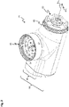
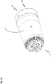
- figure 2 shows a perspective view of the in figure 1 shown active arm module 25.
- the active arm module 25 is also constructed identically in each case across the subassemblies, although only the geometric design is correspondingly adapted in a different manner. In other words, the active J-shaped active arm modules 25 of the different assemblies are scaled relative to one another.
- the first connection side 40 is arranged in a plane of rotation perpendicular to the axis of rotation Ra n .
- the second connection side 45 is arranged at an incline radially on the outside with respect to the axis of rotation Ra n and is aligned at an incline, preferably perpendicularly, with respect to the first connection side 40 .
- the first housing 60 has an essentially cylindrical first housing section 80 .
- the first housing section 80 extends essentially around the axis of rotation Ra n .
- a second housing section 85 is arranged laterally on a peripheral side of the first housing section 80 on the first housing section 80, the second housing section 85 being narrower than the first housing section 80 in the axial direction Ara n .
- the second housing section 85 is essentially trough-shaped.
- the second connection side 45 is arranged on the second housing section 85 on a side facing away from the first housing section 80 . In this case, the second connection side 45 protrudes beyond the second housing section 85 .
- the second connection side 45 can be arranged eccentrically in relation to a maximum longitudinal extent in the axial direction Ara n .
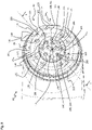
- figure 3 shows a perspective view of a section of the active arm module 25.
- the first connection side 40 has a first connection plate 95 .
- the first connection plate 95 is, for example, circular in plan view and extends perpendicularly to a first assembly axis 100, the first assembly axis 100 being configured as an active arm module 25 as a rotation axis Ra n in an embodiment of the arm module. In other words, the first assembly axis 100 and the axis of rotation Ra n overlap.
- the first connection plate 95 preferably has an external thread 110 on a first outer peripheral side 105 .
- the external thread 110 has multiple threads. It is of particular advantage here if the external thread 110 has at least three, preferably four, threads. It is also advantageous if the external thread 110 is in the form of a fine thread.
- the first connection side 40 has a first contact side 101 .
- the first contact side 101 has a first end face 115 and a second end face 155 , the first end face 115 being arranged radially on the outside of the second end face 155 .
- a first end toothing 116 adjoins the first outer circumferential side 105 on the first end face 115 of the first connecting plate 95 in the radial direction Rra n inward.
- the first spur gearing 116 is designed, for example, as a Hirth gearing.
- the first end toothing 116 has a plurality of first teeth 120 which are offset in the circumferential direction and which, in the embodiment example, are identical to one another.
- a first tooth tip 121 of the first tooth 120 is flat and runs in a plane of rotation perpendicular to the axis of rotation Ra n and thus parallel to the first end face 115.
- a first tooth base 122 which is arranged between two first teeth 120 in the circumferential direction Ura n , is formed by the first face 115 .
- Each of the first tooth flanks 123 of the first tooth 120 is oriented towards the axis of rotation Ra n with at least one direction.
- the first tooth base 122 is arranged in the circumferential direction between two facing first tooth flanks 122 .
- a first tooth space 124 is arranged between each of two first teeth 120 and is delimited in the circumferential direction by the first tooth flanks 123 and in the axial direction by the first tooth base 122 .
- At least one first fastening means 140 is arranged, for example, radially on the inside of the first face toothing 116 .
- the first fastening means 140 can be embodied as a first screw, for example.
- a first screw head of the first screw can be countersunk in the first connecting plate 95 .
- a plurality of first fastening means 140 are preferably arranged on the first connecting plate 95 , with each of the first fastening means 140 being arranged radially on the inside of the first tooth 120 .
- the first fastening means 140 is arranged on a first circular path 145 running around the axis of rotation Ra n . In this case, for example, per first tooth 120 there are two first fastening means 140 radially on the inside of a first tooth 120 arranged.
- At least one first indentation 125 can be arranged in the first tooth 120 .
- the first indentation 125 can be formed like a bore.
- the first indentation 125 may open radially inward to an inner tooth peripheral side 130 of the first tooth 120 .
- the first indentation 125 extends to approximately the level of the first end face 125, so that an indentation base of the first indentation 125 and the first end face 115 merge seamlessly.
- two identical first indentations 125 are provided for each first tooth 120 .
- the first indentations 125 can be arranged on a common fourth circular path 335 around the axis of rotation Ra n .
- the first connection side 40 has a first connection element 150 radially on the inside of the first fastening means 140 .
- the first connecting element 150 has the second end face 155 , the second end face 155 being configured to run parallel to the first end face 115 .
- the first connecting element 150 is arranged on a second circular path 165 about the axis of rotation Ra n by means of at least one second fastening means 160, preferably several in the circumferential direction Ura n offset from one another.
- the second fastening means 160 is embodied as a second screw, for example, with a second screw head of the second fastening means 160 being countersunk in the first connecting element 150 .
- the second circular path 165 and the first circular path 145 are arranged concentrically to one another.
- a center point lies on the axis of rotation Ra n and thus on the first assembly axis 100.
- three second fastening means 160 are arranged at 90° angles to one another with respect to the axis of rotation Ra n , so that between two second fastening means 160 a Angle of 180° is present as an example.
- the first connecting element 150 has a first pin receptacle 170 in the circumferential direction Ura n between the two second fastening means 160, which are arranged, for example, at a distance of 180° from one another.
- the first pin receptacle 170 is designed as a through opening, for example, and is arranged in the circumferential direction Ura n centrally on the second circular path 165 between the two second fastening means 160, which are arranged by 180°, for example.
- the first connection side 40 also has a pin 175, the pin 175 on the back (in figure 3 not shown) is screwed into the first connection plate 95. Included the pin 175 passes through the first pin receptacle 170 and, together with the second fastening means 160, fastens the first connection element 150 to the first connection plate 95. The pin 175 protrudes over the second end face 155 and extends parallel to the first assembly axis 100 or the axis of rotation Ra n .
- the first connecting plate 95 has at least one of the following first materials: metal, aluminum, steel, titanium-aluminum alloy, high-strength aluminum alloy, AW7075, fiber-reinforced plastic, glass-fiber-reinforced plastic (GRP), carbon-fiber-reinforced plastic (CRP).
- the first connection element 150 has at least one of the following second materials: an electrically non-conductive material, plastic, thermoplastic, polyamide, PA GF30, PA6 GF 30.
- the pin 175 has at least one of the following third materials: metal, aluminum, steel, electrically conductive plastic, brass, copper. Because the pin 175 is screwed into the first connection plate 95 on the back, the pin 175 is electrically connected to the first connection plate 95 . Furthermore, the pin 175 fastens the first connection element 150 to the first connection plate 95.
- the first connection element 150 also has a first fluid contact device 180 .
- the first fluid contact device 180 is embodied in the embodiment as a socket or female, for example.
- the first fluid contact device 180 has at least one first fluid contact 185 .
- the fluid contact device 180 has second to fourth fluid contacts 186 to 188 in addition to the first fluid contact 185 .
- Each of the first through fourth fluid contacts 185-188 is fluidically isolated from the other first through fourth fluid contacts 185-188.
- the first to fourth fluid contacts 185 to 188 are formed by a tube receptacle 190 embodied as a blind hole in the first connection element 150 .
- the first to fourth fluid contacts 185 to 188 are formed identical to each other.
- the tube receptacle 190 opens out at the second end face 155.
- the tube receptacle 190 has a sealing surface 195 on a first inner peripheral side.
- a fluid connection channel 200 each opens out at a base of the tube receptacle 190.
- the fluid connection channels 200 run fluidically separated from one another in the first connection plate 95.
- the first to fourth fluid contacts 185 to 188 are arranged at least partially on the second circular path 165. There are the first to fourth fluid contacts 185 to 188 are arranged with their central axis offset slightly inwards in relation to the second circular path 165 .
- the first to fourth fluid contacts 185 to 188 are offset from one another by 90° in the circumferential direction Ura n .
- One of the first to fourth fluid contacts 185 to 188 is arranged in the circumferential direction Ura n centrally between two second fastening means 160 or centrally between the pin 175 and a second fastening means 160 arranged closest to the pin 175 in the circumferential direction Ura n .
- the first connection side 40 on the first connection element 150 has a first power contact device 205 radially on the inside of the second circular path 165 and thus also of the first fluid contact device 180 and the second fastening means 160 .
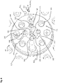
- figure 4 shows an enlarged section of the in figure 3 shown first connection side 40 of the active arm module 25.
- the first connection side 40 also has a first contact device 220, the first contact device 220 being designed for data transmission and having a first contact element 225, for example.
- the first contact element 225 is arranged to run on the first mounting axis 100 and extends along the first mounting axis 100.
- the first contact element 225 is, for example, light-conducting and designed to transmit the optical signal.
- the first contact device 220 is designed as a socket and has a contact receptacle 230 , the contact receptacle 230 being formed like a blind hole in the first connection element 150 , the first contact element 225 extending in the contact receptacle 230 .
- the first contact receptacle 230 opens out on the second end face 155.
- the first power contact device 205 is arranged in the radial direction Rra n between the first fluid contact device 180 and the first contact device 220 .
- This configuration has the advantage that the first connection side 40 has a particularly low installation space requirement in the radial direction Rra n .
- the first power contact device 205 has, for example, in addition to a first power contact 210, at least one second power contact 211, preferably also a third and fourth power contact 212, 213.
- the first to fourth power contacts 210 to 213 are each arranged offset to one another in the circumferential direction Ura n , for example, at a 90° angle.
- the connecting element 150 has a first power contact receptacle 235 for each first to fourth power contact 210, 211, 212, 213.
- the first power contact receptacle 235 is designed as a through opening in the first connection element 150 .
- the first power contact receptacle 235 opens into the second end face 155.
- Each of the first to fourth power contacts 210 to 213 is designed identically to the other first to fourth power contacts 210 to 213, for example.
- Each of the first through fourth power contacts 210 through 213 is socket-shaped.
- the first to fourth power contacts 210 to 213 protrude beyond the first end face 155 and each have an associated contact surface 240, 245 on an inner peripheral side.
- the contact surface 240, 245 is cylindrical.
- the contact surface 240, 245 can further extend beyond a bottom of the first to fourth power contacts 210 to 213.
- the first power contact 210 has a first contact surface 240 and the second power contact 211 has a second contact surface 245 .
- first power contact 210 can be connected to a first pole, generally referred to as the first connection
- second power contact 211 can be connected to a second pole, generally referred to as the second connection, of the electrical energy source.
- the first to fourth power contacts 210 to 213 are formed in a circular shape. In this case, a cross-sectional area is significantly smaller than that of the first to fourth fluid contacts.
- the first to fourth power contacts 210 to 213 are electrically insulated from one another by the electrically non-conductive first connection element 150 .
- the first to fourth power contacts 210 to 213 are arranged together in a plane in which the axis of rotation Ra n and the second fastening means 160 are arranged.
- the first to fourth power contacts 210 to 213 are arranged, for example, concentrically on a third circular path 215 around the first assembly axis 100 or the axis of rotation Ra n .
- the first power contact device 205 is designed to transmit electrical power, for example for supplying the active arm module 25 and/or the passive arm module with electrical energy.
- the electrical energy source can be embodied as a DC voltage source, for example.
- the first and second power contacts 210, 211 can each be connected to a pole of the DC voltage energy source.
- the third and fourth power contacts 212, 213 can each be connected to a further pole of a further DC voltage energy source or an AC voltage energy source, with the two DC voltage energy sources being able to have a different voltage, for example.
- electrical power from two (different) electrical energy sources can be transmitted separately from one another via the first connection side 40 .
- figure 5 shows a perspective view of the in figure 3 active arm module 25.
- the second connection side 45 is mechanically connected to the first housing 60 in a torque-proof manner.
- the second connection side 45 has a second connection plate 300 , a second fluid contact device 305 , a second contact device 310 , a second power contact device 315 and a second contact side 320 .
- the second connection plate 300 is oriented parallel to the first assembly axis 100 and the axis of rotation Ra n , for example.
- the second connection plate 300 essentially has a circular shape in plan view.
- a second mounting axis 325 is inclined, preferably aligned perpendicular to the first mounting axis 100 .
- the second contact side 320 and the second connection plate 300 are aligned perpendicular to the second mounting axis 325 .
- the second fluid contact device 305, the second contact device 310 and the second power contact device 315 are fastened to the second connection plate 300.
- the second fluid contact device 305, the second contact device 310 and the second power contact device 315 extend along or parallel to the second mounting axis 325.
- the second connection plate 300 is non-rotatably connected to the first housing 60 by means of a third fastening means 330, preferably a plurality of third fastening means 330 which are offset relative to one another in the circumferential direction with respect to the second mounting axis 325 and which can be embodied, for example, as third screws mechanically connected.
- the third fastening means 330 are arranged on the fourth circular path 335 circumferentially around the second mounting axis 325 at regular intervals, for example.
- the third screw can have a third screw head 331 , the third screw head 331 protruding beyond a second end face 380 of the second contact side 320 and resting on the second end face 380 .
- the third screw head 331 has a smaller maximum outer diameter than the first indentation (in figure 3 shown) of the first connection side 40.
- the second connection plate 300 is surrounded on the circumference by a fastening ring 340 of the active arm module 25 .
- the fastening ring 340 has an internal thread 350 on a second inner peripheral side 345 , the internal thread 350 being designed to correspond or at least complement the external thread 110 on the first connection side 40 .
- the fastening ring 340 is arranged in an axially fixed manner with respect to the first housing 60 . However, the fastening ring 340 can be rotated about the second mounting axis 325 relative to the first housing 60 .
- the first connection side 40.2 of the second active arm module 25.2 is placed on the second connection side 45.1 of the first active arm module 40.1 and the internal thread 350 is screwed onto the external thread 110 by rotating the fastening ring 340.
- the first contact side 101 is pressed against the second contact side 320 .
- the fastening ring 340 preferably has at least one of the following fourth materials: metal, aluminum, steel, titanium, aluminum alloy, high-strength aluminum alloy, AW7075, fiber-reinforced plastic, glass fiber-reinforced plastic (GRP), carbon fiber-reinforced plastic (CRP).
- fourth materials metal, aluminum, steel, titanium, aluminum alloy, high-strength aluminum alloy, AW7075, fiber-reinforced plastic, glass fiber-reinforced plastic (GRP), carbon fiber-reinforced plastic (CRP).
- a tool holder 360 is arranged on a second outer peripheral side 355, which is essentially cylindrical in the embodiment, tool holder 360 being an example is designed as a blind hole.
- a (raised) Torque can be introduced into the fastening ring 340 in order to loosen the fastening ring 340 from the external thread 110 .
- the fastening ring 340 encompasses the second connecting plate 300 on the peripheral side.
- the second end toothing 365 is preferably designed as a Hirth toothing.
- the second end toothing 365 can be designed to complement or preferably correspond to the first end toothing 116 .
- the second end toothing 365 is arranged in the radial direction between the fourth circular path 335 and/or the third fastening means 300 and the fastening ring 340 .
- the third fastening means 300 connects the second connection side 45 to the first housing
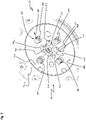
- figure 6 shows a top view of the second connection side 45 of the in figure 2 shown active arm module 25.
- the first face gear 116 and the second face gear 365 are designed to correspond to one another.
- the second end toothing 365 has a plurality of second teeth 370 which are offset from one another in the circumferential direction and which are arranged on a common reference circle around the second assembly axis 325 .
- a second indentation 375 can be arranged in each second tooth 370 of the second face toothing 365, with a third fastening means 330 being arranged in each case in the second indentation 375.
- the second indentation 375 is designed to be open radially inwards.
- the second indentation 375 is designed to correspond to the second screw head 331 and accommodates the second screw head 331 .
- Each of the second teeth 370 has a second tooth flank 371 in each case.
- the second spur toothing 365 has a second tooth base 372 , which extends in a plane perpendicular to the second assembly axis 325 .
- the second tooth base 372 and the third end face 380 are arranged in a common plane and are designed to be stepless with respect to one another.
- Each of the second teeth 370 has a second crest 373 that is planar and extends in a plane perpendicular to the second mounting axis 325 .
- a second interdental space 374 is arranged in each case between second teeth 370 which are arranged closest in the circumferential direction with respect to the second assembly axis.
- the second contact side 320 is designed to essentially correspond to the first contact side.
- the second contact side 320 has the third end face 380 and a fourth end face 385 , the third end face 380 being arranged radially on the inside adjacent to the fastening ring 340 .
- the third end face 380 has an approximately ring-shaped configuration in the plan view, the second end face toothing 365 and the third fastening means 330 being arranged on the third end face 380 .
- the second connection plate 300 has a connection receptacle 390 for receiving the first connection element 150 .
- the connection receptacle 390 is designed to correspond to the first connection element 150 and is delimited at its base by the fourth end face 385 .
- the second fluid contact device 305 is arranged on the fourth end face 385 .
- the second fluid contact device 305 corresponds to the first fluid contact device (cf. Figures 3 and 4 ) educated.
- the second fluid contact device 305 can have a fifth fluid contact 395 .
- the second fluid contact device 305 preferably also has a sixth to eighth fluid contact 396 to 398, so that the second fluid contact device 305 and the first fluid contact device 180 have the same number of fluid contacts 395 to 398.
- the fifth to eighth fluid contacts 395 to 398 are arranged, for example, offset by 90° in the circumferential direction in relation to the second assembly axis 325 on a fifth circular path 400 around the second assembly axis 325 .
- a second pin receptacle 405 is arranged centrally in the second connecting plate 300, for example.
- the second pin receptacle 405 can be designed, for example, as a blind hole or as a bore in the second connection plate 300 .
- the second pin receptacle 405 corresponds to the pin 175 (cf. Figures 3 and 4 ) educated. Pin receptacle 405 is offset radially outwards from fifth circular path 400, but partially overlaps fifth circular path 400.
- the second contact device 310 is arranged on the second mounting axis 325 and extends along the second mounting axis 325.
- the second power contact device 315 is arranged radially between the second contact device 310 and the second fluid contact device 305 .
- the second power contact device 315 is designed to correspond to the first power contact device 205 and is designed in the form of a plug or as a male configuration in the embodiment.
- figure 7 shows a perspective view of the in figure 6 shown second connection side 45 of the active arm module 25.
- the second contact device 310 is designed as a plug/male and corresponds to the first contact device 220 .
- the second contact device 310 has a second contact element 421, wherein the second contact element 421 is arranged centrally on the second mounting axis 325 and is sleeve-shaped.
- the second contact element 421 at least one in figure 7 non-illustrated lens or a lens arrangement of the second contact device 310 can be arranged.
- the second contact element 421 protrudes beyond the fourth end face 385 .
- the second power contact device 315 has a fifth power contact 410 designed to correspond to the first power contact, with the fifth power contact 410 being designed in the form of a pin.
- the fifth power contact 410 has a third contact surface 415 on the circumference and/or on the end face.
- the fifth power contact 410 is arranged in a second power contact receptacle 409 and is set back with respect to the fourth end face 385 .
- the fifth power contact 410 can be spring-mounted in the second contact receptacle 409 .
- the second power contact device 315 also has, for example, a sixth, seventh and eighth power contact 411, 412, 413, which are also designed as pin-shaped, for example, and are designed identically to the fifth power contact 410 in the embodiment.
- the sixth to eighth power contacts 411 to 413 are also set back in a second power contact receptacle 409 .
- the set-back arrangement of the fifth to eighth power contacts 410, 411, 412, 413 protects the fifth to eighth power contacts 410, 411, 412, 413 from being touched.
- the fifth to eighth fluid contacts 395 to 398 are formed identically to each other in the embodiment, for example.
- the fifth fluid contact 395 is embodied in a tubular manner, for example.
- the fifth fluid contact 395 extends parallel to the second mounting axis 325.
- the fifth fluid contact 395 is connected to the fourth end face 385 with a fixed end.
- the fifth fluid contact 395 is embodied as a male, for example.
- the second fluid contact 395 opens out at a distance on a side facing away from the fourth end face 385 .
- each fifth fluid contact 395 has a first sealing element 425, preferably an O-ring, which can be arranged in a groove, for example, on the fifth fluid contact 395 on the peripheral side.
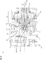
- figure 8 shows a perspective half longitudinal section through the in figure 2 shown active arm module 25.
- the active arm module 25 has a drive device 430 , a transfer device 435 , a control device 445 and at least one converter 450 in the first housing 60 .
- the drive device 430 has an electrical machine 455 and a transmission 460, the transmission 460 being connected to the electrical machine 455 on the input side.
- the transmission 460 On the output side, the transmission 460 has an output flange 491 .
- the output flange 461 is non-rotatably connected to the connection plate 95 by means of the first fastening means 140 . In this case, for example, a screw of the first fastening means 140 is screwed into the output flange 461 .
- the electric machine 455 drives the transmission 460 at an engine speed.
- the transmission 460 reduces the engine speed to an output speed, preferably with a reduction ratio of 1:30 to 1:200.
- the output speed is present at the output flange 461.
- the output flange 461 of the transmission 460 drives the first connection side 40 via the first fastening means 140 and in this case in particular the first connection plate 95 .
- the transmission 460 is arranged axially between the electrical machine 455 and the first connection side 40 in relation to the axis of rotation Ra n , which overlaps with the first assembly axis 100 .
- the first hollow shaft 470 Due to the non-rotatable connection with the first connecting plate 95, the first hollow shaft 470 is non-rotatably coupled to the output flange 461 and rotates at the output speed.
- the transfer device 435 is arranged axially on a side of the drive device 430 facing away from the first connection side 40 .
- the transfer device 435 is preferably connected fluidly to the second fluid contact device 305 on the outlet side, for example with a plurality of hose lines 465 .
- the control device 445 is arranged at the opposite end of the first housing 60 to the first connection side 40 in the axial direction relative to the axis of rotation Ra n .
- the converter 450 is arranged on top of the transfer device 435 , ie on a side facing the second connection side 45 .
- the first connection side 40 also has a first hollow shaft 470 .
- the drive device 430 also has a second hollow shaft 475, the second hollow shaft 475 connecting the electric machine 455 to the transmission 460.
- the second hollow shaft 475 thus runs at the engine speed and the first hollow shaft 470 at the output speed.
- the second hollow shaft 475 is shorter in the axial direction than the first hollow shaft 470.
- the first hollow shaft 470 extends essentially in the longitudinal direction over the entire drive device 430 and the transfer device 435.
- the first hollow shaft 470 extends through the second hollow shaft 475 and the drive device 430 and the transfer device 435.
- a first optical waveguide 480 is arranged centrally in the first hollow shaft 470, the first optical waveguide 480 being connected to the first contact device 220 at one (axial) end.
- the first optical fiber 480 is optically connected to the converter 450 at another end.
- the first optical waveguide 480 is arranged to run on the axis of rotation Ra n and is rotationally fixed to the hollow shafts 470, 475.
- the first contact device 220 is designed as a rotary transmitter and couples the (rotatable) first contact element 225 to the first, which is arranged rotationally fixed Fiber Optic 480.
- the optical signal is transmitted from the first contact device 220 via the first optical waveguide 480 to the converter 450.
- the converter 450 converts the optical signal into an electrical data signal.
- the converter 450 is optically connected to the second contact element 421 on the output side by means of a second optical waveguide 485 .
- the converter 450 converts the electrical data signal detected by the converter 450 back into a (further) optical signal and the further optical signal is transmitted via the second optical waveguide 485 to the second contact element 421 .
- first optical waveguide 480 Arranged radially on the outside of the first optical waveguide 480, in alignment with the first to fourth power contacts 210 to 213, is an associated bore 490 in the first hollow shaft 470 and the first connection plate 95, which essentially extends over the entire length of the first hollow shaft 470 in the axial direction .
- the first to fourth power contacts 210 to 213 are arranged in the bore 490, although an insulating element can be provided in the bore 490 in order to establish an electrical contact in the first connection plate 95 between the first to fourth power contacts 210 to 213 and the to prevent electrically conductive connection plate 95.
- a first electrical connection 495 is arranged in each bore 490 so as to be electrically insulated from the first hollow shaft 470 .
- the first electrical connection 495 is electrically connected at one end to the associated first through fourth power contacts 210 through 213, respectively.
- the transfer device 435 has a slip ring unit 500 for each first to fourth power contact, with a first electrical connection 495 being electrically connected at the other end to a slip ring unit 500 in each case.
- a further slip ring unit 500 is provided for a ground contact between the first housing 60 and the first hollow shaft 470 or via the first hollow shaft 470 with the first connecting plate 95 .
- Each slip ring unit 500 is connected to one of the assigned fifth to eighth power contacts 410 to 413 in each case by means of a second electrical connection 505 .
- the first power contact 210 is electrically connected to the fifth power contact 410 via the first and second electrical connection 495, 505 and the slip ring unit 500.
- the control unit 445 is electrically connected via an in figure 8 third electrical connection (not shown) is electrically connected to at least two, preferably four, of the first to eighth power contacts 210 to 413 via the slip ring unit 500 .
- the third and fourth power contacts 212, 213 and the seventh and eighth power contacts 412, 413 can be used individually for electrical power transmission from the other electrical (direct or alternating voltage) energy source, so that, for example, the seventh and eighth power contacts 412, 413 have a different voltage level is present than at the fifth and sixth power contacts 410, 411.
- figure 9 shows a perspective sectional view along an in figure 3 Section plane XX shown through an active arm module 25.
- the first connecting plate 95 and the first hollow shaft 470 are formed in one piece and from the same material.
- the first hollow shaft 470 has a smaller outside diameter than the first connecting plate 95.
- the first fluid connection channel 200 is arranged in the first connection plate 95 .
- the first fluid connection channel 200 opens out on the first connection side 40 at the first fluid contact 185.
- the first fluid connection channel 200 opens out into a fluid channel 510.
- the fluid channel 510 is arranged both in the first hollow shaft 470 and running in the axial direction in the first connecting plate 95.
- the first fluid connection channel 200 runs obliquely to the fluid channel 510 radially from the outside inwards.
- the fluid channel 510 can be formed as a bore.
- the fluid channel 510 is arranged radially on the inside of the first fluid contact 185 .
- a second sealing element 515 is provided on the first connection side 40 for fluidic sealing of the fluid connection channel 200 and the fluid channel 510 .
- the second sealing element 515 is arranged axially between the first connection element 150 and the first connection plate 95 .
- the second sealing element 515 can be designed as an O-ring.
- a second sealing element 515 is provided for each first to fourth fluid contact 185, 186, 187, 188 and is arranged concentrically to the respective first to fourth fluid contact 185, 186, 187, 188.
- the slip ring unit 500 On the axial end of the first hollow shaft 470 facing away from the first connection side 40, the slip ring unit 500 has a closing element 520, which closes the fluid channel 510 at the rear, so that on the front side, on the axial end facing away from the first connection side 40, the fluid channel 510, which is designed as a bore, is closed in a fluid-tight manner in a simple manner .
- the closing element 520 can be part of the slip ring unit 500 .
- a fluid connection channel 200 and a fluid channel 510 are provided for each of the first to fourth fluid contacts 185, 186, 187, 188, with the fluid connection channel 200 and the fluid channel 510 being arranged fluidically separate from the other fluid connection channels and fluid channels 510.
- the fluidic separation of the first to fourth fluid contacts 185 to 188 is also maintained in the first hollow shaft 470 and the first connection plate 95 .
- the transfer device 435 is embodied as a rotary transmitter and fluidly couples the first hollow shaft 470 to a hose line 465 arranged in a rotationally fixed manner in the first housing interior.
- the fluid channel 510 is fluidically connected via the transfer device 435 to a hose line 465 each with an assigned fifth to eighth fluid contact of the second fluid contact device .
- each (first to fourth) fluid contact 185, 187 is fluidically connected to an associated and correspondingly arranged (fifth to eighth) fluid contact on the second connection side.
- the fluidic connection is also maintained when the first connection side 40 rotates about the axis of rotation Ra n .
- the rotation about the axis of rotation Ra n is not limited by the configuration described above and can be almost unlimited.
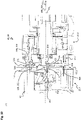
- figure 10 shows a sectional view along an in figure 1 Section plane YY shown through the first active arm module 25.1 and the second active arm module 25.2 of the in figure 1 Robot arm 20 of the industrial robot 10.
- the active and passive arm modules 25, 30 shown are analogous to the connection explained below between the second connection side 45.1 of the first active arm module 25.1 and the first connection side 40.2 of the second active arm module 25.2.
- the fastening ring 340 is screwed with the internal thread 350 onto the external thread 110, so that the first contact side 101 and the second Contact side 320 are pressed together axially and the first and second contact sides 101, 320 at least partially flat against each other.
- the first connection side 40.2 of the second active arm module 25.2 and the second connection side 45.1 of the first active arm module 25.1 are moved towards one another along the first and second assembly axes 100, 325 until the contact sides abut one another.
- the fastening ring 340 has a collar 525 which extends radially inwards and engages between the second connecting plate 300 and the housing 60 .
- the fastening ring 340 is arranged such that it can be rotated in the circumferential direction about the second assembly axis 325, which overlaps with a second axis of rotation Ra 2 .
- the attachment ring 340 is screwed onto the external thread 110 and tightened around the first and second assembly axis 100, 325 with a predefined tightening torque.
- the fastening ring 340 is supported on the collar 525 at the rear. Due to the predefined tightening torque, the first connection side 40 and the second connection side 45 are pressed against one another with an axial force F A resulting from the tightening torque.
- the first and second fluid contact devices 180, 305 also interlock and provide a fluid-tight connection between the first connection side 40.2 of the second active arm module 25.2 and the second connection side 45.1 of the first arm module 25.1.
- the fifth fluid contact 395 engages in the first fluid contact 185 .
- the first sealing element 425 arranged in the groove seals off the fifth fluid contact 395 from the first fluid contact 185 .
- the second fluid contact 395 opens out axially opposite to the first fluid connection channel 200.
- the fluid 51 preferably compressed air or coolant, for example for cooling a machining process or hydraulic fluid, can be provided, which is first introduced via the robot base 15 into the third passive arm module 30.3 and then into the first active arm module 25.1.
- the fluid 51 is transferred and forwarded via the first active arm module 25.1 from the first connection side to the second connection side 45.1 of the first active arm module 25.1.
- the forwarding takes place via the first connection side 40.1 of the first active arm module 25.1 (hereinafter referred to figures 1 , 9 and 10 referred together), via the fluid connection channel 200 and fluid channel 510, the transfer device 435 and the hose line 465 to the second fluid contact device 305.
- the first and second fluid contact devices 180, 305 in contact fluidly connect the second active arm module 25.2 to the second connection side 45.1 of the first active arm module 25.1 on the first connection side 40.2 of the second active arm module 25.2.
- the fluid 51 is transferred via the second active arm module 25.2, just as just described, in the first active arm module 25.1 to the second connection side 45.2 of the second active arm module 25.2.
- the fluid 51 can be transferred from the robot base 15 in the direction of the end effector.
- the same fluid 51 can flow through the individual first and second fluid contacts 185, 395 in parallel, or the individual first and second fluid contacts 185, 395 can be fluidically separated from one another and/or in different directions be flowed through with fluid 51.
- Different fluids 51 can also be routed via the fluid channels and fluid connection channels that are fluidically separated from one another.
- the end effector can be supplied via up to four separately switchable fluidic connections.
- the end effector can also be controlled from the robot base 15 by means of solenoid valves, for example.
- Two or more fluid connection channels and fluid channels can also be connected in parallel so that, for example, a particularly high mass flow of fluid 51 can be transmitted from the robot base 15 to the end effector via the first and second fluid contact devices 180, 305.
- figure 11 shows a sectional view along an in figure 1 Section plane ZZ shown by the in the figures 1 shown first and second active arm module 25.1, 25.2.
- the pin 175 engages in the second pin receptacle 405 assigned to it.
- the second terminal board 300, the first terminal board 95, and the pin 175 are formed of an electrically conductive material.
- the second connection side 45.1 of the first active arm module 25.1 is electrically connected to a ground contact, for example via the robot base 15.
- the pin 175 contacts the second pin receptacle 405 electrically and thus not only provides an orientation of the first connection side 40.2 of the second active arm module 25.2 to the second connection side 45.1 of the first active arm module 25.1 about the second axis of rotation Ra 2 , which overlaps with the first and second mounting axis 100, 325, but also provides also ensures a ground contact via the electrically conductive first hollow shaft 470, the transfer device 435 and the first housing 60 to the second connection side 45.2 of the second active arm module 25.2.
- the first contact device 220 also makes contact with the second contact device 310, so that the robot base 15 via the third passive arm module 30.3, the first active arm module 25.1 and then via the second connection side 45.1 of the first active arm module 25.1 and the first connection side 40.2 of the second active arm module 25.2 away the optical signal can be transmitted to the second arm module 25.2.
- the optical signal is further in the active arm module 25, for example the second active arm module 25.2 as in figure 8 explained, to the second connection side 45.2 of the second active arm module 25.2.
- the first power contact device 205 also makes contact with the second power contact device 315.
- the fifth to eighth power contacts 410 to 413 rest on the respective associated first to fourth power contacts 210 to 213 on the face side.
- the fifth to eighth power contact 410 to 413 can be resiliently mounted in the second connection side 45.1 of the first active arm module 25.1 and pressed against the respectively associated second to fourth power contact 210 to 213 by means of a prestressing force.
- the electrical power can be used to operate the drive device 430 of the first active arm module 25.1 and to operate the control unit 445.
- the electrical power can be transmitted at least partially to the second active arm module 25.2 via the second connection side 45.1 of the first active arm module 25.1 and the first connection side 40.2 of the second active arm module 25.2.
- the second active arm module 25.2 also provides the electrical power on the second connection side 45.2 of the second active arm module 25.2 through the electrical connection between the first and second power contact device 205, 315 and the second active arm module 25.2.
- the electrical power can be transferred from the robot base 15 in the direction of the end effector via the active arm modules 25 and the passive arm modules 30 the connection pages are transferred.
- the active arm module 25 can also be supplied with the electrical power to operate the control unit 445, the converter 450 and the drive device 430 and electrical power can also be passed on to operate the end effector or electrical power can be transmitted to operate additional units or peripheral devices of the robot arm 20 will.
- figure 12 shows an in figure 1 marked section V of the in figure 1 shown industrial robot 10.
- the first face gearing 116 and the second face gearing 365 mesh a.
- the first end toothing 116 and the second end toothing 365 are designed to be at least complementary, preferably corresponding to one another.
- the first and second end teeth 116, 365 are preferably designed as Hirth teeth, so that when the first connection side 40.2 of the second active arm module 25.2 is mounted on the second connection side 45.1 of the first active arm module 25.1, the two connection sides 40.2, 45.1 mentioned are relatively radial to one another Direction to the first and second assembly axis 100, 325, which then correspond to the second axis of rotation Ra 2 in the assembled state, center.
- a pre-centering can be done by engaging the pin 175 in the pin receptacle 405 (in figure 10 shown).
- first tooth flank 123 and the second tooth flank 371 slide on one another and orient the first connection side 40.2 and the second connection side 45.1 both in the circumferential direction Ura 2 and in the radial direction in relation to the first and second assembly axis 100, 325.
- first and second tooth flanks 123, 371 arranged opposite one another in the circumferential direction rest against one another.
- the first tooth 123 engages in the second tooth gap 372 between two second teeth 370 that are closest in the circumferential direction.
- the first end toothing 116 and the second end toothing 365 are flank-centered, for example, so that a first axial gap 590 is arranged between the first tooth crest 221 and the second tooth root 372 .
- the second tooth 370 also engages in the first tooth space 124 .
- the second tooth crest 373 is arranged at a distance from the first tooth base 122 in the axial direction by a second axial gap 595 .
- the transmission of the resulting axial force F A between the first spur gearing 116 and the second spur gearing 365 thus takes place exclusively via the first and second tooth flanks 123, 371.
- the torque to be transmitted between the first connection side 40.2 and the second connection side 45.1 is also essentially exclusively transmitted via the first and second tooth flanks 123, 371. This avoids mechanical loading of the contact device, the power contact device and the fluid contact device in the circumferential direction.
- figure 13 shows a detail of a sectional view along an in figure 1 shown cutting plane WW through the in figure 1 shown industrial robot 10.
- the interface is not shown closed.
- the first indentation 125 is designed to correspond, at least in sections, to the second screw head 331 of the third fastening means 330 .
- the second screw head 331 engages in the first indentation 125 , the second screw head 331 being arranged at a distance from the indentation bottom of the first indentation 125 in the axial direction. This avoids overdetermination on the first and second connection sides 40, 45.
- the centering in the circumferential direction and radial direction ensures reliable insertion of the first and second contact device 220, 310 and the first and second fluid contact device 180, 305 and the first and second power contact device 205, 315.
- the orientation in the circumferential direction and the coding in the circumferential direction take place when the pin 175 engages in the second pin receptacle 405.
- the drive device 430 of the second active arm module 25.2 is activated, for example, the first connection side 40.2 of the second active arm module 25.2 is rotated relative to the first housing 60 of the second active arm module 25.2 and to the second connection side 45.1 of the first active arm module 25.1.
- the industrial robot 10 can be controlled according to all six first to sixth axes of rotation Ra 1 to Ra 2 .
- Both the electrical power, the fluid 51 and the optical signal for data communication which is transmitted according to the EtherCAT standard, for example, can be transmitted from the robot base 15 to the end effector on the inside of the robot arm 20 without limiting a rotation about the rotation axis Ra n .
- the industrial robots 10 shown, in particular the active arm modules 25, have the advantage that they have a standardized and/or uniform and/or identical design and by means of the individual active and/or passive arm modules 25, 30 and the corresponding first and second connection sides 40 , 45 can be easily mounted together depending on the required rotation axes Ra n .
- figure 14 12 shows a perspective view of a passive arm module 30 according to a first embodiment.
- passive arm modules 30 can also be provided in addition to the active arm modules 25 .
- the passive arm module 30 shown can, for example, be the one shown in figure 1 shown second passive arm module 30.2.
- the passive arm module 30 is essentially identical to the active arm module 25 .
- the third connection side 50 is connected to the fourth connection side 55 within the second housing interior 75 of the respective passive arm module 30 in terms of fluids, data technology, preferably optically, and power-electrically.
- both the third connection side 50 and the fourth connection side 55 are connected to the second housing 70 in a rotationally fixed manner.
- the fourth connection side 55 is formed analogously to the first connection side of the active arm module, so that with regard to the detailed description on FIG Figures 3 and 4 is referenced.
- the third connection side 50 is designed analogously to the second connection side of the active arm module, so here on the detailed description of the Figures 5 to 7 is referenced.
- the first and second transfer device, the converter, the control device and the drive device waived.
- the first fluid contact device on the third connection side 50 is fluidic directly by means of a fluid connection with the second fluid contact device on the fourth connection side 55
- the first contact device is preferably optical with the second contact device directly by means of a further optical waveguide and the first power contact device is directly, for example by means of electrical cables, with the second contact device electrically connected.
- figure 15 12 shows a perspective view of a passive arm module 30 according to a second embodiment.
- the passive arm module 30 shown is essentially identical to that shown in FIG figure 14 shown passive arm module 30 is formed.
- the passive arm module 30 shown here has two fourth connection sides 55, which are each designed analogously to the first connection side of the active arm module.
- the arm module 30 shown can be used, for example, as the first arm module 30.1 of the in figure 1 shown robot arm 15 can be used.
- figure 16 shows a sectional representation of an active arm module 25 according to a second embodiment.
- the active arm module 25 is essentially identical to that shown in FIGS Figures 1 to 13 shown active arm module 25 of in figure 1 shown industrial robot 10 formed. In the following, only the differences of the in figure 16 shown active arm module 25 compared to that in FIGS Figures 1 to 13 shown embodiment of the active arm module 25 received.
- the first connection side 40 and the second connection side 45 are identical to one another.
- the second connection side 45 substantially as in the Figures 1 to 13 explain first connection side 40 is formed.
- both connection sides 40, 45 are designed as females, for example.
- the first and second end teeth on the two connection sides 40, 45 are dispensed with.
- the fastening ring on the second connection side 45 is also dispensed with.
- the first outer peripheral side 105 is essentially cylindrical, with a groove 535, for example V-shaped, being arranged in the first outer peripheral side 105.
- the groove 535 is circumferential to the respective axis of rotation Ra n arranged.
- the robot arm additionally has a connector between each two active arm modules 25 to be connected.
- figure 17 shows a longitudinal section through connector 540.
- the connector 540 has a connector connection side 545 on both sides, the connector connection sides 545 being configured identically to one another.
- the connector 540 forms a kind of passive arm module, which is designed to be particularly short in the axial direction.
- the connector connection side 545 is, for example, as a male at least complementary, preferably corresponding to the first connection side 40 or the second connection side 45 of the in figure 16 shown active arm module formed.
- each connector connection side 545 has on the outside a web 555 which is arranged on a connector housing 550 and is of cylindrical design.
- a clamping ring 560 which can be rotated about the axis of rotation Ra n is arranged radially on the outside of the web 555 .
- First ball receptacles 565 are provided at regular intervals in the web 555 , one ball 570 being arranged in each ball receptacle 565 .
- figure 18 shows a cross section through the in figure 17 shown clamping ring 560 of the connector.
- the clamping ring 560 On a third inner peripheral side 575, the clamping ring 560 has a second ball receptacle 580 at regular intervals, which is closed to the outside. This is followed in the circumferential direction Ura n in relation to the axis of rotation Ra n in each case by a cone section 585, the cone section 585 narrowing in its radius R in the circumferential direction in relation to the axis of rotation Ra n .
- the connector 540 is attached with a connector connection side 545 to one of the two connection sides 40, 45 of the in figure 16 shown active arm module 25 postponed.
- the first or second connection side 40, 45 is connected to the connector 540 in terms of data, power and fluids.
- the balls 570 engage in the groove 535 for mechanical attachment. Does the connector 540 have a final position through it achieved that the first or second contact side rests against a base of the connector terminal side 545, the clamping ring 560 is rotated in the circumferential direction Ura n .
- the balls 570 are pressed radially inwards into the groove 535 by the cone section 585 .
- connection side 40, 45 This creates a frictional connection between the connector 540 and the connection side 40, 45.
- the other connection side 40, 45 of the next active arm module 25 is then pushed in on the other connector connection side 545 and the connection of the further active arm module 25 to the connector 540 takes place analogously, as just explained.
- two active arm modules 25 can be connected to one another.
- a passive arm module has two identical third and fourth connection sides that are identical to the first connection side and can also be connected to a corresponding connection side 40 , 45 of the active arm module 25 using the connector 540 .
- a torque can also be transmitted via the connector 540, so that the (active) first connection side 40 of the connector 540, but also the next active or passive arm module 25, 30 attached to the connector 540, can be rotated.
- This configuration has the advantage that the arm modules 18 can be fitted to one another particularly quickly.
Landscapes
- Engineering & Computer Science (AREA)
- Robotics (AREA)
- Mechanical Engineering (AREA)
- Manipulator (AREA)
Claims (15)
- Module de bras (18) pour un bras de robot modulaire (20) d'un robot industriel (10),- présentant un premier boîtier (60), un premier côté de raccordement (40) et un deuxième côté de raccordement (45),- dans lequel le premier côté de raccordement (40) présente une première plaque de raccordement (95) et un premier dispositif de contact (220), et le deuxième côté de raccordement (45) est relié mécaniquement au premier boîtier (60) de manière solidaire en rotation et présente une deuxième plaque de raccordement (300),- dans lequel le premier dispositif de contact (220) est disposé au niveau de la première plaque de raccordement (95) et s'étend en parallèle à un premier axe de montage (100),- dans lequel le premier côté de raccordement (40) peut être relié à un autre module de bras (18) du bras de robot (20),- dans lequel un signal optique et/ou un signal électrique peuvent être transmis par le premier dispositif de contact (220) pour la transmission de données,- dans lequel la deuxième plaque de raccordement (300) est entourée côté circonférence par une bague de fixation (340), et la bague de fixation (340) présente un taraudage (350) sur un côté circonférentiel intérieur (345),- dans lequel la bague de fixation (340) est reliée à un premier boîtier (60) du module de bras (18) en rotation autour du deuxième axe de montage (325),- dans lequel une première denture frontale (116) est disposée sur la première plaque de raccordement (95),- dans lequel la deuxième plaque de raccordement (300) présente une deuxième denture frontale (365),- dans lequel la première denture frontale (116) et la deuxième denture frontale (365) sont réalisées de manière complémentaire et/ou de manière à se correspondre mutuellement,- dans lequel un filetage (110) est disposé sur un premier côté circonférentiel extérieur (105) de la première plaque de raccordement (95) de manière périphérique autour du premier axe de montage (100),- dans lequel le taraudage (35) est réalisé de manière à correspondre au filetage (110),caractérisé en ce que- le premier côté de raccordement (40) présente un premier dispositif de contact fluidique (180),- dans lequel le premier dispositif de contact fluidique (180) est disposé au niveau de la première plaque de raccordement (95) et s'étend en parallèle à un premier axe de montage (100),- dans lequel un fluide (51), en particulier de l'air comprimé ou un liquide hydraulique, peut être transmis par l'intermédiaire du premier dispositif de contact fluidique (180),- dans lequel la bague de fixation (340) est reliée de manière axialement fixe à un premier boîtier (60) du module de bras (18).
- Module de bras (18) selon la revendication 1,- dans lequel la première denture frontale (116) et/ou la deuxième denture frontale (365) est/sont réalisée(s) sous forme de denture Hirth, et/ou- dans lequel la deuxième denture frontale (365) est disposée côté intérieur à la suite de la bague de fixation (340).
- Module de bras (18) selon l'une quelconque des revendications précédentes,- dans lequel la première plaque de raccordement (95) et la première denture frontale (116) sont réalisées d'un seul tenant et en venant de matière, et/ou- dans lequel la deuxième plaque de raccordement (300) et la deuxième denture frontale (365) sont réalisées d'un seul tenant et en venant de matière.
- Module de bras (18) selon l'une quelconque des revendications précédentes,- dans lequel la première denture frontale (116) est adjacente côté intérieur au premier côté circonférentiel extérieur (105) dans la direction radiale (Ran, Rpn),- dans lequel le premier dispositif de contact fluidique (180) est disposé radialement entre le premier dispositif de contact de puissance (205) et la première denture frontale (116).
- Module de bras (18) selon l'une quelconque des revendications précédentes,- dans lequel la première denture frontale (116) présente au moins une première dent (120),- dans lequel la première dent (120) présente une première encoche (125) qui s'étend dans la direction axiale le long du premier axe de montage (100),- dans lequel le deuxième côté de raccordement (45) est relié au premier boîtier (60) de manière solidaire en rotation au moyen d'un troisième moyen de fixation (330),- dans lequel le troisième moyen de fixation (330) dépasse de la deuxième plaque de raccordement (300),- dans lequel la première encoche (125) est réalisée au moins par endroits de façon à correspondre au troisième moyen de fixation (330), et/ou- dans lequel le premier dispositif de contact de puissance (205) est disposé entre le premier dispositif de contact (220) et le premier dispositif de contact fluidique (180) dans la direction radiale (Ran, Rpn) par rapport au premier axe de montage (100),- dans lequel, radialement côté extérieur par rapport au premier dispositif de contact de puissance (205), le premier dispositif de contact fluidique (180) est disposé entre le premier dispositif de contact de puissance (205) et le premier côté circonférentiel extérieur (105) au niveau de la première plaque de raccordement (95),- dans lequel un fluide (51), en particulier de l'air comprimé ou un liquide hydraulique, peut être transmis par l'intermédiaire du premier dispositif de contact fluidique (180), un signal optique et/ou un signal électrique pour la transmission de données peut/peuvent être transmis par l'intermédiaire du premier dispositif de contact (220), et une puissance électrique pour alimenter le module de bras (18) en énergie électrique peut être transmise par l'intermédiaire du premier dispositif de contact de puissance (205).
- Module de bras (18) selon l'une quelconque des revendications précédentes,- dans lequel le deuxième côté de raccordement (45) présente un deuxième dispositif de contact fluidique (305) réalisé de façon à correspondre au premier dispositif de contact fluidique (180), un deuxième dispositif de contact de puissance (315) réalisé de façon à correspondre au premier dispositif de contact de puissance (205), et un deuxième dispositif de contact (310) réalisé de façon à correspondre au premier dispositif de contact (220),- dans lequel le deuxième dispositif de contact fluidique (305), le deuxième dispositif de contact de puissance (315) et le deuxième dispositif de contact (310) sont disposés au niveau de la deuxième plaque de raccordement (300), et le deuxième dispositif de contact fluidique (305), le deuxième dispositif de contact de puissance (315) et le deuxième dispositif de contact (310) s'étendent le long d'un deuxième axe de montage (325),- dans lequel le premier dispositif de contact fluidique (180) est relié au deuxième dispositif de contact fluidique (305) de manière directement ou indirectement fluidique dans le premier boîtier (60), et le premier dispositif de contact (220) est relié au deuxième dispositif de contact (310) de manière directement ou indirectement informatique pour la transmission du signal optique et/ou électrique dans le premier boîtier (60),- dans lequel le premier dispositif de contact de puissance (205) et le deuxième dispositif de contact de puissance (315) sont reliés ensemble de manière directement ou indirectement électrique dans le premier boîtier (60),- dans lequel le premier dispositif de contact de puissance (205) et le deuxième dispositif de contact de puissance (315) sont reliés ensemble de manière électrique,- dans lequel le fluide (51) peut être transmis par l'intermédiaire du deuxième dispositif de contact fluidique (305), la puissance électrique peut être transmise par l'intermédiaire du deuxième dispositif de contact de puissance (315), et le signal optique et/ou électrique peut/peuvent être transmis par l'intermédiaire du deuxième dispositif de contact (310) .
- Module de bras (18) selon l'une quelconque des revendications précédentes,- dans lequel le premier dispositif de contact (220) présente plusieurs premiers éléments de contact (225) disposés dans la direction circonférentielle par rapport au premier axe de montage (100),- dans lequel les premiers éléments de contact (225) sont disposés de manière concentrique par rapport au premier axe de montage (100),- dans lequel le signal de données électrique peut être transmis par l'intermédiaire du premier élément de contact (225).
- Module de bras (18) selon l'une quelconque des revendications précédentes,- dans lequel le premier dispositif de contact fluidique (180) présente plusieurs premiers contacts fluidiques (185) disposés de manière décalée dans la direction circonférentielle (Uran, Urp) par rapport au premier axe de montage (100),- dans lequel les premiers contacts fluidiques (185) sont disposés de manière concentrique par rapport au premier axe de montage (100) et sont réalisés de manière identique entre eux,- dans lequel les premiers contacts fluidiques (185) sont séparés fluidiquement les uns des autres et/ou sont au moins partiellement connectés fluidiquement en parallèle.
- Module de bras (18) selon la revendication 8,- dans lequel le deuxième dispositif de contact fluidique (305) présente au moins un deuxième contact fluidique (395),- dans lequel le deuxième contact fluidique (395) s'étend en parallèle au deuxième axe de montage (325),- dans lequel le premier contact fluidique (185) est relié au deuxième contact fluidique (395) pour échanger un fluide (530) entre eux,- dans lequel le premier contact fluidique (185) présente un logement de tuyau (190) et le deuxième contact fluidique (395) présente une section de tuyau (396),- dans lequel le logement de tuyau (190) et la section de tuyau (396) sont réalisés de façon à se correspondre au moins côté circonférence.
- Module de bras (18) selon l'une quelconque des revendications précédentes,- présentant une broche (175) s'étendant à distance et en parallèle au premier axe de montage (100),- dans lequel la broche (175) est reliée électriquement et mécaniquement à la première plaque de raccordement (95) et dépasse de la première plaque de raccordement (95),- dans lequel la broche (175) est réalisée pour venir en prise dans un logement de broche (405) de l'autre module de bras (18) pour le codage et/ou le positionnement du module de bras (25) par rapport à l'autre module de bras (18), et/ou- dans lequel la deuxième plaque de raccordement (300) présente un logement de broche (405),- dans lequel le logement de broche (405) est réalisé de façon à correspondre à la broche (175) et est conçu pour recevoir une broche (175) d'un autre module de bras (18).
- Module de bras (18) selon l'une quelconque des revendications précédentes,- dans lequel le module de bras (18) est réalisé comme un module de bras actif (25),- présentant un dispositif d'entraînement (430),- dans lequel le premier côté de raccordement (40) est monté en rotation autour du premier axe de montage (100) et est relié au dispositif d'entraînement (430) par liaison de transmission de couple,- dans lequel le dispositif d'entraînement (430) est réalisé pour faire tourner le premier côté de raccordement (40) de manière contrôlable autour du premier axe de montage (100),- ou- dans lequel le module de bras (18) est réalisé comme un module de bras passif (30),- dans lequel la première plaque de raccordement (95) est reliée au premier boîtier (60) de manière solidaire en rotation sur un côté du premier boîtier (60) détourné vers le deuxième côté de raccordement (45) .
- Module de bras (25) qui est réalisé comme un module de bras (25) actif selon la revendication 11,- dans lequel le premier côté de raccordement (40) présente un arbre creux (470),- dans lequel l'arbre creux (470) est relié à un côté sortie du dispositif d'entraînement (430) par liaison de transmission de couple,- dans lequel l'arbre creux (470) traverse le dispositif d'entraînement (430), et une première extrémité axiale de l'arbre creux (470) est reliée à la première plaque de raccordement (95) de manière solidaire en rotation, et une deuxième extrémité axiale de l'arbre creux (470) est disposée à distance du dispositif d'entraînement (430),- dans lequel au moins un canal de fluide (510) relié fluidiquement au premier dispositif de contact fluidique (180) et au moins une liaison de données électrique reliée au premier dispositif de contact (220) sont disposés dans l'arbre creux (470).
- Bras de robot (20) pour un robot industriel (10) comprenant au moins un premier module de bras (18) et un deuxième module de bras (18),- dans lequel le premier module de bras (18) et le deuxième module de bras (18) sont réalisés respectivement selon l'une quelconque des revendications 1 à 12,- dans lequel la bague de fixation (340) du premier module de bras (18) est vissée sur le premier côté de raccordement (40) du deuxième module de bras (18) de telle sorte que le taraudage (350) du premier module de bras (18) et le filetage (110) du premier côté de raccordement (40) du deuxième module de bras (18) viennent en prise l'un dans l'autre,- dans lequel la première denture frontale (116) du premier côté de raccordement (40) et la deuxième denture frontale (365) du deuxième côté de raccordement (45) viennent en prise l'une dans l'autre,- dans lequel le premier côté de raccordement (40) du deuxième module de bras (18) est relié mécaniquement au deuxième côté de raccordement (45) du premier module de bras (18) pour transmettre des forces d'appui et/ou des forces d'entraînement entre le premier module de bras (18) et le deuxième module de bras (18),- dans lequel le fluide (51) pour un effecteur terminal pouvant être raccordé au bras de robot (20) et/ou le signal optique et/ou le signal électrique pour une transmission de données et pour la commande des deux modules de bras (18) et/ou de l'effecteur terminal peuvent être échangés par l'intermédiaire des premiers et deuxièmes côtés de raccordement (40, 45), reliés ensemble, du premier module de bras (18) et du deuxième module de bras (18).
- Bras de robot (20) selon la revendication 13,- dans lequel la première denture frontale (116) et la deuxième denture frontale (365) sont réalisées l'une par rapport à l'autre de telle sorte que lors d'un montage du premier côté de raccordement (40) sur le deuxième côté de raccordement (45), la deuxième plaque de raccordement (300) est alignée de manière centrée par rapport au premier axe de montage (100) suite à un coulissement des deux dentures frontales (116, 365) l'une contre l'autre, et/ou- dans lequel le deuxième côté de raccordement (45) présente le logement de broche (405),- dans lequel le logement de broche (405) est réalisé pour l'orientation et/ou le codage du deuxième côté de raccordement (45) par rapport au premier côté de raccordement (40) et est disposé dans la deuxième plaque de raccordement (300),- dans lequel, à l'état monté du premier côté de raccordement (40) et du deuxième côté de raccordement (45) l'un contre l'autre, la broche (175) vient en prise dans le logement de broche (405) et relie électriquement de préférence la première plaque de raccordement (95) du premier côté de raccordement (40) à la deuxième plaque de raccordement (300) pour réaliser un contact de masse entre les deux modules de bras (18).
- Robot industriel (10),- présentant un bras de robot (20) selon la revendication 13 ou 14 et une base de robot (15),- dans lequel le premier côté de raccordement (40) du premier module de bras (18) est tourné vers la base de robot (15),- dans lequel le fluide (51) et/ou le signal optique et/ou le signal électrique peuvent être transmis par l'intermédiaire du premier côté de raccordement (40) du deuxième module de bras (18) et du deuxième côté de raccordement (45) du premier module de bras (18) entre le premier côté de raccordement (40), tourné vers la base de robot (15), du premier module de bras (18) et un deuxième côté de raccordement (45), détourné de la base de robot (15), du deuxième module de bras (18).
Applications Claiming Priority (2)
| Application Number | Priority Date | Filing Date | Title |
|---|---|---|---|
| DE102019120128.4A DE102019120128A1 (de) | 2019-07-25 | 2019-07-25 | Armmodul, Roboterarm und Industrieroboter |
| PCT/EP2020/070974 WO2021013995A1 (fr) | 2019-07-25 | 2020-07-24 | Module de bras, bras de robot et robot industriel |
Publications (2)
| Publication Number | Publication Date |
|---|---|
| EP4003662A1 EP4003662A1 (fr) | 2022-06-01 |
| EP4003662B1 true EP4003662B1 (fr) | 2023-01-04 |
Family
ID=71846378
Family Applications (1)
| Application Number | Title | Priority Date | Filing Date |
|---|---|---|---|
| EP20747371.1A Active EP4003662B1 (fr) | 2019-07-25 | 2020-07-24 | Module de bras, bras de robot et robot industriel |
Country Status (5)
| Country | Link |
|---|---|
| US (1) | US12208518B2 (fr) |
| EP (1) | EP4003662B1 (fr) |
| CN (1) | CN114174004B (fr) |
| DE (1) | DE102019120128A1 (fr) |
| WO (1) | WO2021013995A1 (fr) |
Families Citing this family (34)
| Publication number | Priority date | Publication date | Assignee | Title |
|---|---|---|---|---|
| DE102019120135A1 (de) | 2019-07-25 | 2021-01-28 | Beckhoff Automation Gmbh | Armmodul für einen modularen Roboterarm eines Industrieroboters |
| DE102019120116A1 (de) | 2019-07-25 | 2021-01-28 | Beckhoff Automation Gmbh | Aktives und passives Armmodul, Endmodul, Roboterarm und Industrieroboter |
| DE102019120131B4 (de) | 2019-07-25 | 2023-01-12 | Beckhoff Automation Gmbh | Optische Rotations-Übertragungseinrichtung für ein Automatisierungssystem, Armmodul für einen modularen Roboterarm sowie Industrieroboter |
| JP1666996S (fr) * | 2019-12-13 | 2020-08-31 | ||
| JP1666999S (fr) * | 2019-12-13 | 2020-08-31 | ||
| JP1666998S (fr) * | 2019-12-13 | 2020-08-31 | ||
| JP1693581S (fr) * | 2019-12-13 | 2021-08-30 | ||
| JP6872050B1 (ja) * | 2020-02-03 | 2021-05-19 | 日本航空電子工業株式会社 | ロボット装置及び無線コネクタ |
| DE102020103058B3 (de) | 2020-02-06 | 2021-07-08 | Beckhoff Automation Gmbh | Armmodul, Roboterarm und Industrieroboter |
| US11673257B2 (en) * | 2020-03-17 | 2023-06-13 | Faro Technologies, Inc. | Long-bolt cartridge clamping system |
| USD937334S1 (en) * | 2020-08-24 | 2021-11-30 | Beijing Keyi Technology Co., Ltd. | Joint robot module |
| USD937333S1 (en) * | 2020-08-24 | 2021-11-30 | Beijing Keyi Technology Co., Ltd. | Robot arm |
| USD937335S1 (en) * | 2020-08-24 | 2021-11-30 | Beijing Keyi Technology Co., Ltd. | Brain robot module |
| USD942518S1 (en) * | 2020-08-24 | 2022-02-01 | Beijing Keyi Technology Co., Ltd. | Two-wheel car robot |
| USD937336S1 (en) * | 2020-08-24 | 2021-11-30 | Beijing Keyi Technology Co., Ltd. | Snap robot module |
| JP1707772S (ja) * | 2021-06-23 | 2022-02-17 | 産業用ロボット | |
| JP1707768S (ja) * | 2021-06-23 | 2022-02-17 | 産業用ロボット | |
| JP1717780S (ja) * | 2021-06-23 | 2022-06-21 | 産業用ロボット | |
| JP1707770S (ja) * | 2021-06-23 | 2022-02-17 | 産業用ロボット | |
| JP1707769S (ja) * | 2021-06-23 | 2022-02-17 | 産業用ロボット | |
| JP1707771S (ja) * | 2021-06-23 | 2022-02-17 | 産業用ロボット | |
| JP1708715S (ja) * | 2021-06-23 | 2022-03-02 | 産業用ロボット | |
| USD1059450S1 (en) * | 2021-12-14 | 2025-01-28 | Agile Robots AG | Round lightcap for robotic arm |
| US12528205B2 (en) * | 2022-03-04 | 2026-01-20 | Fanuc Corporation | Wrist device and joint device |
| CN114347084B (zh) * | 2022-03-22 | 2022-06-14 | 北京九服机器人科技有限公司 | 人工、机器人柔性交互应用的标准快换装置 |
| USD1020828S1 (en) * | 2022-03-31 | 2024-04-02 | Agile Robots AG | Robotic arm for medical and industrial purposes |
| TWI810960B (zh) | 2022-06-02 | 2023-08-01 | 直得科技股份有限公司 | 機器手臂關節、連接件及機器手臂 |
| USD1061651S1 (en) * | 2022-06-10 | 2025-02-11 | Agile Robots AG | Oval lightcap for robotic arm |
| USD1034728S1 (en) * | 2022-08-10 | 2024-07-09 | Boston Dynamics, Inc. | Robotic device |
| USD1033501S1 (en) * | 2022-08-10 | 2024-07-02 | Boston Dynamics, Inc. | Robotic device |
| USD1102502S1 (en) * | 2023-06-16 | 2025-11-18 | Agile Robots AG | Robotic arm head |
| USD1102504S1 (en) * | 2023-06-16 | 2025-11-18 | Agile Robots AG | Robotic arm head |
| USD1102503S1 (en) * | 2023-06-16 | 2025-11-18 | Agile Robots AG | Robotic arm link |
| CN121245890B (zh) * | 2025-12-05 | 2026-02-27 | 昆山市华霆精密机械有限公司 | 一种多向定位防偏移机器人手臂末端法兰连接结构 |
Citations (3)
| Publication number | Priority date | Publication date | Assignee | Title |
|---|---|---|---|---|
| US4370091A (en) * | 1979-07-18 | 1983-01-25 | Ateliers Et Chantiers De Bretagne | Remote manipulator arm |
| EP3372354A1 (fr) * | 2017-03-09 | 2018-09-12 | SUPSI (Scuola Universitaria Della Svizzera Italiana) | Articulation de robot modulaire et robot reconfigurable fabriqué en l'utilisant |
| WO2019081662A1 (fr) * | 2017-10-27 | 2019-05-02 | Creaholic S.A. | Module matériel pour système robotique, et dispositif d'accouplement mécanique |
Family Cites Families (59)
| Publication number | Priority date | Publication date | Assignee | Title |
|---|---|---|---|---|
| DE2904867A1 (de) * | 1979-02-09 | 1980-08-21 | Gewerk Eisenhuette Westfalia | Steckkupplung fuer mehradrige hydraulische kabel |
| FR2496185A1 (fr) | 1980-12-16 | 1982-06-18 | Renault | Articulation a motorisation hydraulique |
| DE3105105C2 (de) * | 1981-02-12 | 1984-05-17 | Kuka Schweissanlagen + Roboter Gmbh, 8900 Augsburg | Haltevorrichtung für bewegliche Schweißwerkzeuge mit einem Drehanschluß für die Beschickung des Werkzeuges |
| DE3435119C2 (de) * | 1984-09-25 | 1986-08-07 | Gildemeister-De Vlieg System-Werkzeuge Gmbh, 4800 Bielefeld | Werkzeug- oder Werkstückhalteranordnung für spanende Werkzeugmaschinen |
| JPS61246806A (ja) | 1985-04-24 | 1986-11-04 | Fanuc Ltd | ロボツト制御装置 |
| DE3717597A1 (de) | 1986-07-09 | 1988-01-21 | Eisenmann Foerdertech Gmbh | Robotergelenkkopf in modulbauweise |
| CH672898A5 (fr) * | 1987-05-11 | 1990-01-15 | Praezisions Werkzeuge Ag | |
| US5069524A (en) * | 1988-03-07 | 1991-12-03 | Honda Giken Kogyo Kabushiki Kaisha | Robot hand optical fiber connector coupling assembly |
| US4990839A (en) | 1988-12-09 | 1991-02-05 | Schonlau William J | Modular robotic system |
| US5039193A (en) | 1990-04-03 | 1991-08-13 | Focal Technologies Incorporated | Fibre optic single mode rotary joint |
| US5205701A (en) * | 1990-06-04 | 1993-04-27 | Canon Kabushiki Kaisha | Industrial robot |
| SE512968C2 (sv) * | 1991-10-21 | 2000-06-12 | Rotech Tooling Ab | Svivelkoppling |
| AUPM570694A0 (en) | 1994-05-19 | 1994-06-09 | O'Brien, Brian Jonathan | Shape variable structure |
| WO1996008675A1 (fr) * | 1994-09-12 | 1996-03-21 | Westinghouse Electric Corporation | Systeme robotise de maintenance gere et telecommande |
| DE19517852A1 (de) | 1995-05-16 | 1995-12-14 | Uwe Kochanneck | Multiblock Robot |
| US5633963A (en) | 1995-12-12 | 1997-05-27 | Raytheon Company | Optical rotary joint for single and multimode fibers |
| GB9713765D0 (en) * | 1997-07-01 | 1997-09-03 | Engineering Services Inc | Reconfigurable mudular drive system |
| DE19738934A1 (de) | 1997-09-05 | 1999-03-11 | Fibro Gmbh | Drehdurchführung für Drehvorrichtungen, insbesondere für Handhabungseinrichtungen und Industrieroboter |
| DE29808801U1 (de) | 1998-05-15 | 1999-09-23 | KUKA Schweissanlagen GmbH, 86165 Augsburg | Drehanschluß mit modularen Baueinsätzen |
| US6628338B1 (en) | 1998-07-08 | 2003-09-30 | Elbex Video Ltd. | Direct drive electric motor apparatus incorporating slip ring assembly |
| DE29912409U1 (de) | 1999-07-15 | 1999-09-23 | Schunk GmbH & Co. KG Fabrik für Spann- und Greifwerkzeuge, 74348 Lauffen | Elektrisches Dreh- oder Schwenkmodul |
| DE10006226A1 (de) | 2000-02-11 | 2001-08-23 | Schunk Gmbh & Co Kg | Werkzeugadapter an einer Roboterschnittstelle |
| JP4150992B2 (ja) | 2000-04-07 | 2008-09-17 | 日本サーボ株式会社 | ステップリング付同軸出力中空軸減速体を有する回転電機 |
| CN2735363Y (zh) | 2004-09-23 | 2005-10-19 | 天津大学 | 动态数据传输光电混合光纤旋转连接器 |
| DE102006047207B3 (de) | 2006-10-05 | 2008-07-03 | Fachhochschule Koblenz | Optischer Drehverteiler für Lichtwellenleiter |
| DE202007016161U1 (de) * | 2007-11-16 | 2009-03-26 | Dinse Gmbh | Roboterhalterung für fluidgekühlte Fügewerkzeuge |
| US8786385B1 (en) | 2009-11-12 | 2014-07-22 | Curtis D Lorenc | Rotary joint for radio frequency electromagnetic waves and light waves |
| WO2011107144A1 (fr) | 2010-03-02 | 2011-09-09 | Abb Research Ltd | Système pour connecter électriquement un outil à un poignet de robot, et procédé pour cette opération |
| WO2012136645A1 (fr) | 2011-04-04 | 2012-10-11 | GAT Gesellschaft für Antriebstechnik mbH | Transmetteur optique de rotation et procédé et dispositif pour la fabrication dudit transmetteur optique de rotation |
| JP5834473B2 (ja) | 2011-04-28 | 2015-12-24 | セイコーエプソン株式会社 | ロボット |
| CN103085082B (zh) | 2011-11-04 | 2015-10-14 | 鸿富锦精密工业(深圳)有限公司 | 机器人臂部件 |
| US8909008B1 (en) | 2012-03-26 | 2014-12-09 | Owlink Technology, Inc. | Active optical rotary coupler |
| US9475199B2 (en) * | 2012-06-05 | 2016-10-25 | TRACLabs, Inc. | Apparatus, systems, and methods for reconfigurable robotic manipulator and coupling |
| JP5729410B2 (ja) | 2013-03-19 | 2015-06-03 | 株式会社安川電機 | ロボット |
| US20150068350A1 (en) | 2013-09-10 | 2015-03-12 | Seiko Epson Corporation | Robot arm and robot |
| EP3044536B1 (fr) * | 2013-09-13 | 2017-11-22 | Carl Zeiss Industrielle Messtechnik GmbH | Procédé et dispositif de mesure de taraudages d'une pièce usinée au moyen d'un capteur optique |
| US9677602B1 (en) | 2013-11-25 | 2017-06-13 | Space Systems/Loral, Llc | Caging mechanism for a single- or multi-axis positioning mechanism |
| DE102013019869B4 (de) | 2013-11-28 | 2022-01-13 | Abb Schweiz Ag | Roboterarm mit Eingabemodul |
| US20180111275A1 (en) | 2014-08-01 | 2018-04-26 | Kugar Inc. | Modular system for constructing robots |
| KR101699040B1 (ko) * | 2014-08-14 | 2017-01-23 | (주)케이엔알시스템 | 유압 로터리 액추에이터 |
| DE202014010032U1 (de) | 2014-12-18 | 2016-03-21 | Kuka Systems Gmbh | Kupplung mit kontaktloser Energie- und Datenübertragung |
| US9751220B2 (en) | 2015-03-31 | 2017-09-05 | Google Inc. | Flexure based torque sensor |
| WO2016168470A1 (fr) | 2015-04-15 | 2016-10-20 | Moog Inc. | Connexion électrique rotative optique |
| CN106541398A (zh) | 2015-09-21 | 2017-03-29 | 深圳市恒科通机器人有限公司 | 组合型机器人及其活动关节机构 |
| JP6506195B2 (ja) | 2016-03-09 | 2019-04-24 | ファナック株式会社 | 回転軸モジュールおよび多関節ロボット |
| DE202016104373U1 (de) | 2016-08-09 | 2016-08-29 | HARTING Deutschland GmbH & Co. KG | Drehübertrager |
| JP6533200B2 (ja) | 2016-09-20 | 2019-06-19 | 平田機工株式会社 | 部品支持装置および製造方法 |
| JP2018094703A (ja) | 2016-12-16 | 2018-06-21 | セイコーエプソン株式会社 | ロボット |
| DE102017001943A1 (de) * | 2017-02-28 | 2018-08-30 | Eisele Pneumatics Gmbh & Co. Kg | Anschlusssystem |
| JP6988152B2 (ja) | 2017-05-08 | 2022-01-05 | セイコーエプソン株式会社 | ロボット |
| US10780575B2 (en) | 2017-06-22 | 2020-09-22 | Phd, Inc. | Robot end effector cuff |
| DE102017119179A1 (de) | 2017-08-22 | 2019-02-28 | Schunk Gmbh & Co. Kg Spann- Und Greiftechnik | Drehdurchführung für eine Handhabungseinheit |
| JP6958200B2 (ja) | 2017-09-29 | 2021-11-02 | セイコーエプソン株式会社 | ロボット |
| US10981281B2 (en) * | 2017-12-01 | 2021-04-20 | Macdonald, Dettwiler And Associates Inc. | Low-profile manipulator interface system |
| US11413761B2 (en) * | 2018-05-29 | 2022-08-16 | Abb Schweiz Ag | Modular platform for robotic end effector |
| US11433534B2 (en) | 2019-03-07 | 2022-09-06 | Abb Schweiz Ag | Robotic arm including edge computer and cabling arrangement facilitating flexible function advanced distal arm end tooling |
| DE102019120135A1 (de) | 2019-07-25 | 2021-01-28 | Beckhoff Automation Gmbh | Armmodul für einen modularen Roboterarm eines Industrieroboters |
| DE102019120116A1 (de) | 2019-07-25 | 2021-01-28 | Beckhoff Automation Gmbh | Aktives und passives Armmodul, Endmodul, Roboterarm und Industrieroboter |
| DE102019120131B4 (de) | 2019-07-25 | 2023-01-12 | Beckhoff Automation Gmbh | Optische Rotations-Übertragungseinrichtung für ein Automatisierungssystem, Armmodul für einen modularen Roboterarm sowie Industrieroboter |
-
2019
- 2019-07-25 DE DE102019120128.4A patent/DE102019120128A1/de not_active Withdrawn
-
2020
- 2020-07-24 CN CN202080053383.2A patent/CN114174004B/zh active Active
- 2020-07-24 WO PCT/EP2020/070974 patent/WO2021013995A1/fr not_active Ceased
- 2020-07-24 EP EP20747371.1A patent/EP4003662B1/fr active Active
-
2022
- 2022-01-21 US US17/581,382 patent/US12208518B2/en active Active
Patent Citations (3)
| Publication number | Priority date | Publication date | Assignee | Title |
|---|---|---|---|---|
| US4370091A (en) * | 1979-07-18 | 1983-01-25 | Ateliers Et Chantiers De Bretagne | Remote manipulator arm |
| EP3372354A1 (fr) * | 2017-03-09 | 2018-09-12 | SUPSI (Scuola Universitaria Della Svizzera Italiana) | Articulation de robot modulaire et robot reconfigurable fabriqué en l'utilisant |
| WO2019081662A1 (fr) * | 2017-10-27 | 2019-05-02 | Creaholic S.A. | Module matériel pour système robotique, et dispositif d'accouplement mécanique |
Also Published As
| Publication number | Publication date |
|---|---|
| WO2021013995A1 (fr) | 2021-01-28 |
| EP4003662A1 (fr) | 2022-06-01 |
| CN114174004B (zh) | 2024-06-14 |
| DE102019120128A1 (de) | 2021-01-28 |
| CN114174004A (zh) | 2022-03-11 |
| US20220143815A1 (en) | 2022-05-12 |
| US12208518B2 (en) | 2025-01-28 |
Similar Documents
| Publication | Publication Date | Title |
|---|---|---|
| EP4003662B1 (fr) | Module de bras, bras de robot et robot industriel | |
| EP3983179B1 (fr) | Module de bras actif et passif, module d'extrémité, bras de robot et robot industriel | |
| EP3983178B1 (fr) | Module de bras pour un bras robotisé modulaire d'un robot industriel | |
| EP4142987B1 (fr) | Ensemble bras conçu pour un bras de robot modulaire d'un robot industriel | |
| DE102020103058B3 (de) | Armmodul, Roboterarm und Industrieroboter | |
| EP3481605B1 (fr) | Procédé et système de changement automatique d'arbres | |
| EP3800015B1 (fr) | Robots de préhension et/ou de retenue d'objets | |
| DE102016004787A1 (de) | Antriebsvorrichtung für einen Roboter und Verfahren zu ihrer Herstellung | |
| DE102013216449A1 (de) | Industrieroboter mit wenigstens einem Antrieb | |
| DE102016004788A1 (de) | Verfahren zur Herstellung eines Roboters und Vorrichtung zur Durchführung dieses Verfahrens | |
| DE102014009892B4 (de) | Antriebseinheit mit magnetischer Schnittstelle | |
| DE102019120131A1 (de) | Optische Rotations-Übertragungseinrichtung für ein Automatisierungssystem, Armmodul für einen modularen Roboterarm sowie Industrieroboter | |
| EP3797943B1 (fr) | Installation de manutention | |
| DE9313310U1 (de) | Werkzeugwechseleinrichtung für Manipulatoren | |
| DE202011002899U1 (de) | Werkzeugwechsler für einen Roboterarm mit einer Drehdurchführung für Medien | |
| EP1123784B1 (fr) | Adaptateur d'outil à l'interface d'un robot | |
| DE112019004638T5 (de) | Elektrischer Werkzeugwechsler | |
| WO2018158097A1 (fr) | Système de raccordement | |
| DE102012022252B4 (de) | Antriebseinheit für einen Werkzeugwechsler | |
| DE102020119499A1 (de) | Angetriebene Linearachse sowie Industrieroboter | |
| DE102022108814B4 (de) | Kupplungsvorrichtung zur Verbindung von Bauteilen | |
| EP4056335B1 (fr) | Dispositif pourvu de composants connectés par l'intermédiaire d'une interface de connexion et procédé de connexion de composants | |
| DE102010006617A1 (de) | Betätigungseinrichtung zur mehrachsigen räumlichen Positionierung eines Hilfsmittels und Verfahren zur Steuerung einer Betätigungseinrichtung | |
| DE20213734U1 (de) | Roboterarm mit Greifersystem und Endlosachse |
Legal Events
| Date | Code | Title | Description |
|---|---|---|---|
| STAA | Information on the status of an ep patent application or granted ep patent |
Free format text: STATUS: UNKNOWN |
|
| STAA | Information on the status of an ep patent application or granted ep patent |
Free format text: STATUS: THE INTERNATIONAL PUBLICATION HAS BEEN MADE |
|
| PUAI | Public reference made under article 153(3) epc to a published international application that has entered the european phase |
Free format text: ORIGINAL CODE: 0009012 |
|
| STAA | Information on the status of an ep patent application or granted ep patent |
Free format text: STATUS: REQUEST FOR EXAMINATION WAS MADE |
|
| 17P | Request for examination filed |
Effective date: 20220225 |
|
| AK | Designated contracting states |
Kind code of ref document: A1 Designated state(s): AL AT BE BG CH CY CZ DE DK EE ES FI FR GB GR HR HU IE IS IT LI LT LU LV MC MK MT NL NO PL PT RO RS SE SI SK SM TR |
|
| GRAP | Despatch of communication of intention to grant a patent |
Free format text: ORIGINAL CODE: EPIDOSNIGR1 |
|
| STAA | Information on the status of an ep patent application or granted ep patent |
Free format text: STATUS: GRANT OF PATENT IS INTENDED |
|
| DAV | Request for validation of the european patent (deleted) | ||
| DAX | Request for extension of the european patent (deleted) | ||
| INTG | Intention to grant announced |
Effective date: 20220713 |
|
| GRAS | Grant fee paid |
Free format text: ORIGINAL CODE: EPIDOSNIGR3 |
|
| GRAA | (expected) grant |
Free format text: ORIGINAL CODE: 0009210 |
|
| STAA | Information on the status of an ep patent application or granted ep patent |
Free format text: STATUS: THE PATENT HAS BEEN GRANTED |
|
| AK | Designated contracting states |
Kind code of ref document: B1 Designated state(s): AL AT BE BG CH CY CZ DE DK EE ES FI FR GB GR HR HU IE IS IT LI LT LU LV MC MK MT NL NO PL PT RO RS SE SI SK SM TR |
|
| REG | Reference to a national code |
Ref country code: GB Ref legal event code: FG4D Free format text: NOT ENGLISH |
|
| REG | Reference to a national code |
Ref country code: CH Ref legal event code: EP |
|
| REG | Reference to a national code |
Ref country code: AT Ref legal event code: REF Ref document number: 1541602 Country of ref document: AT Kind code of ref document: T Effective date: 20230115 |
|
| REG | Reference to a national code |
Ref country code: DE Ref legal event code: R096 Ref document number: 502020002318 Country of ref document: DE |
|
| REG | Reference to a national code |
Ref country code: IE Ref legal event code: FG4D Free format text: LANGUAGE OF EP DOCUMENT: GERMAN |
|
| REG | Reference to a national code |
Ref country code: LT Ref legal event code: MG9D |
|
| REG | Reference to a national code |
Ref country code: NL Ref legal event code: MP Effective date: 20230104 |
|
| PG25 | Lapsed in a contracting state [announced via postgrant information from national office to epo] |
Ref country code: NL Free format text: LAPSE BECAUSE OF FAILURE TO SUBMIT A TRANSLATION OF THE DESCRIPTION OR TO PAY THE FEE WITHIN THE PRESCRIBED TIME-LIMIT Effective date: 20230104 |
|
| PG25 | Lapsed in a contracting state [announced via postgrant information from national office to epo] |
Ref country code: RS Free format text: LAPSE BECAUSE OF FAILURE TO SUBMIT A TRANSLATION OF THE DESCRIPTION OR TO PAY THE FEE WITHIN THE PRESCRIBED TIME-LIMIT Effective date: 20230104 Ref country code: PT Free format text: LAPSE BECAUSE OF FAILURE TO SUBMIT A TRANSLATION OF THE DESCRIPTION OR TO PAY THE FEE WITHIN THE PRESCRIBED TIME-LIMIT Effective date: 20230504 Ref country code: NO Free format text: LAPSE BECAUSE OF FAILURE TO SUBMIT A TRANSLATION OF THE DESCRIPTION OR TO PAY THE FEE WITHIN THE PRESCRIBED TIME-LIMIT Effective date: 20230404 Ref country code: LV Free format text: LAPSE BECAUSE OF FAILURE TO SUBMIT A TRANSLATION OF THE DESCRIPTION OR TO PAY THE FEE WITHIN THE PRESCRIBED TIME-LIMIT Effective date: 20230104 Ref country code: LT Free format text: LAPSE BECAUSE OF FAILURE TO SUBMIT A TRANSLATION OF THE DESCRIPTION OR TO PAY THE FEE WITHIN THE PRESCRIBED TIME-LIMIT Effective date: 20230104 Ref country code: HR Free format text: LAPSE BECAUSE OF FAILURE TO SUBMIT A TRANSLATION OF THE DESCRIPTION OR TO PAY THE FEE WITHIN THE PRESCRIBED TIME-LIMIT Effective date: 20230104 Ref country code: ES Free format text: LAPSE BECAUSE OF FAILURE TO SUBMIT A TRANSLATION OF THE DESCRIPTION OR TO PAY THE FEE WITHIN THE PRESCRIBED TIME-LIMIT Effective date: 20230104 |
|
| PG25 | Lapsed in a contracting state [announced via postgrant information from national office to epo] |
Ref country code: SE Free format text: LAPSE BECAUSE OF FAILURE TO SUBMIT A TRANSLATION OF THE DESCRIPTION OR TO PAY THE FEE WITHIN THE PRESCRIBED TIME-LIMIT Effective date: 20230104 Ref country code: PL Free format text: LAPSE BECAUSE OF FAILURE TO SUBMIT A TRANSLATION OF THE DESCRIPTION OR TO PAY THE FEE WITHIN THE PRESCRIBED TIME-LIMIT Effective date: 20230104 Ref country code: IS Free format text: LAPSE BECAUSE OF FAILURE TO SUBMIT A TRANSLATION OF THE DESCRIPTION OR TO PAY THE FEE WITHIN THE PRESCRIBED TIME-LIMIT Effective date: 20230504 Ref country code: GR Free format text: LAPSE BECAUSE OF FAILURE TO SUBMIT A TRANSLATION OF THE DESCRIPTION OR TO PAY THE FEE WITHIN THE PRESCRIBED TIME-LIMIT Effective date: 20230405 Ref country code: FI Free format text: LAPSE BECAUSE OF FAILURE TO SUBMIT A TRANSLATION OF THE DESCRIPTION OR TO PAY THE FEE WITHIN THE PRESCRIBED TIME-LIMIT Effective date: 20230104 |
|
| REG | Reference to a national code |
Ref country code: DE Ref legal event code: R097 Ref document number: 502020002318 Country of ref document: DE |
|
| PG25 | Lapsed in a contracting state [announced via postgrant information from national office to epo] |
Ref country code: SM Free format text: LAPSE BECAUSE OF FAILURE TO SUBMIT A TRANSLATION OF THE DESCRIPTION OR TO PAY THE FEE WITHIN THE PRESCRIBED TIME-LIMIT Effective date: 20230104 Ref country code: RO Free format text: LAPSE BECAUSE OF FAILURE TO SUBMIT A TRANSLATION OF THE DESCRIPTION OR TO PAY THE FEE WITHIN THE PRESCRIBED TIME-LIMIT Effective date: 20230104 Ref country code: EE Free format text: LAPSE BECAUSE OF FAILURE TO SUBMIT A TRANSLATION OF THE DESCRIPTION OR TO PAY THE FEE WITHIN THE PRESCRIBED TIME-LIMIT Effective date: 20230104 Ref country code: DK Free format text: LAPSE BECAUSE OF FAILURE TO SUBMIT A TRANSLATION OF THE DESCRIPTION OR TO PAY THE FEE WITHIN THE PRESCRIBED TIME-LIMIT Effective date: 20230104 Ref country code: CZ Free format text: LAPSE BECAUSE OF FAILURE TO SUBMIT A TRANSLATION OF THE DESCRIPTION OR TO PAY THE FEE WITHIN THE PRESCRIBED TIME-LIMIT Effective date: 20230104 |
|
| PLBE | No opposition filed within time limit |
Free format text: ORIGINAL CODE: 0009261 |
|
| STAA | Information on the status of an ep patent application or granted ep patent |
Free format text: STATUS: NO OPPOSITION FILED WITHIN TIME LIMIT |
|
| PG25 | Lapsed in a contracting state [announced via postgrant information from national office to epo] |
Ref country code: SK Free format text: LAPSE BECAUSE OF FAILURE TO SUBMIT A TRANSLATION OF THE DESCRIPTION OR TO PAY THE FEE WITHIN THE PRESCRIBED TIME-LIMIT Effective date: 20230104 |
|
| 26N | No opposition filed |
Effective date: 20231005 |
|
| PG25 | Lapsed in a contracting state [announced via postgrant information from national office to epo] |
Ref country code: SI Free format text: LAPSE BECAUSE OF FAILURE TO SUBMIT A TRANSLATION OF THE DESCRIPTION OR TO PAY THE FEE WITHIN THE PRESCRIBED TIME-LIMIT Effective date: 20230104 |
|
| PG25 | Lapsed in a contracting state [announced via postgrant information from national office to epo] |
Ref country code: MC Free format text: LAPSE BECAUSE OF FAILURE TO SUBMIT A TRANSLATION OF THE DESCRIPTION OR TO PAY THE FEE WITHIN THE PRESCRIBED TIME-LIMIT Effective date: 20230104 |
|
| PG25 | Lapsed in a contracting state [announced via postgrant information from national office to epo] |
Ref country code: MC Free format text: LAPSE BECAUSE OF FAILURE TO SUBMIT A TRANSLATION OF THE DESCRIPTION OR TO PAY THE FEE WITHIN THE PRESCRIBED TIME-LIMIT Effective date: 20230104 |
|
| REG | Reference to a national code |
Ref country code: BE Ref legal event code: MM Effective date: 20230731 |
|
| PG25 | Lapsed in a contracting state [announced via postgrant information from national office to epo] |
Ref country code: LU Free format text: LAPSE BECAUSE OF NON-PAYMENT OF DUE FEES Effective date: 20230724 |
|
| PG25 | Lapsed in a contracting state [announced via postgrant information from national office to epo] |
Ref country code: LU Free format text: LAPSE BECAUSE OF NON-PAYMENT OF DUE FEES Effective date: 20230724 |
|
| REG | Reference to a national code |
Ref country code: IE Ref legal event code: MM4A |
|
| PG25 | Lapsed in a contracting state [announced via postgrant information from national office to epo] |
Ref country code: BE Free format text: LAPSE BECAUSE OF NON-PAYMENT OF DUE FEES Effective date: 20230731 |
|
| PG25 | Lapsed in a contracting state [announced via postgrant information from national office to epo] |
Ref country code: IE Free format text: LAPSE BECAUSE OF NON-PAYMENT OF DUE FEES Effective date: 20230724 |
|
| PG25 | Lapsed in a contracting state [announced via postgrant information from national office to epo] |
Ref country code: IE Free format text: LAPSE BECAUSE OF NON-PAYMENT OF DUE FEES Effective date: 20230724 |
|
| PG25 | Lapsed in a contracting state [announced via postgrant information from national office to epo] |
Ref country code: BG Free format text: LAPSE BECAUSE OF FAILURE TO SUBMIT A TRANSLATION OF THE DESCRIPTION OR TO PAY THE FEE WITHIN THE PRESCRIBED TIME-LIMIT Effective date: 20230104 |
|
| PG25 | Lapsed in a contracting state [announced via postgrant information from national office to epo] |
Ref country code: BG Free format text: LAPSE BECAUSE OF FAILURE TO SUBMIT A TRANSLATION OF THE DESCRIPTION OR TO PAY THE FEE WITHIN THE PRESCRIBED TIME-LIMIT Effective date: 20230104 |
|
| GBPC | Gb: european patent ceased through non-payment of renewal fee |
Effective date: 20240724 |
|
| PG25 | Lapsed in a contracting state [announced via postgrant information from national office to epo] |
Ref country code: GB Free format text: LAPSE BECAUSE OF NON-PAYMENT OF DUE FEES Effective date: 20240724 |
|
| PG25 | Lapsed in a contracting state [announced via postgrant information from national office to epo] |
Ref country code: CY Free format text: LAPSE BECAUSE OF FAILURE TO SUBMIT A TRANSLATION OF THE DESCRIPTION OR TO PAY THE FEE WITHIN THE PRESCRIBED TIME-LIMIT; INVALID AB INITIO Effective date: 20200724 |
|
| PG25 | Lapsed in a contracting state [announced via postgrant information from national office to epo] |
Ref country code: HU Free format text: LAPSE BECAUSE OF FAILURE TO SUBMIT A TRANSLATION OF THE DESCRIPTION OR TO PAY THE FEE WITHIN THE PRESCRIBED TIME-LIMIT; INVALID AB INITIO Effective date: 20200724 |
|
| PGFP | Annual fee paid to national office [announced via postgrant information from national office to epo] |
Ref country code: DE Payment date: 20250704 Year of fee payment: 6 |
|
| PGFP | Annual fee paid to national office [announced via postgrant information from national office to epo] |
Ref country code: IT Payment date: 20250731 Year of fee payment: 6 |
|
| PGFP | Annual fee paid to national office [announced via postgrant information from national office to epo] |
Ref country code: FR Payment date: 20250723 Year of fee payment: 6 Ref country code: AT Payment date: 20250721 Year of fee payment: 6 |
|
| PGFP | Annual fee paid to national office [announced via postgrant information from national office to epo] |
Ref country code: CH Payment date: 20250801 Year of fee payment: 6 |
|
| PG25 | Lapsed in a contracting state [announced via postgrant information from national office to epo] |
Ref country code: TR Free format text: LAPSE BECAUSE OF FAILURE TO SUBMIT A TRANSLATION OF THE DESCRIPTION OR TO PAY THE FEE WITHIN THE PRESCRIBED TIME-LIMIT Effective date: 20230104 |