EP4003717B1 - Verfahren und anlage zur herstellung von reifen für fahrzeugräder - Google Patents
Verfahren und anlage zur herstellung von reifen für fahrzeugräder Download PDFInfo
- Publication number
- EP4003717B1 EP4003717B1 EP20757666.1A EP20757666A EP4003717B1 EP 4003717 B1 EP4003717 B1 EP 4003717B1 EP 20757666 A EP20757666 A EP 20757666A EP 4003717 B1 EP4003717 B1 EP 4003717B1
- Authority
- EP
- European Patent Office
- Prior art keywords
- path
- location
- stage forming
- crown
- carcass
- Prior art date
- Legal status (The legal status is an assumption and is not a legal conclusion. Google has not performed a legal analysis and makes no representation as to the accuracy of the status listed.)
- Active
Links
Images


Classifications
-
- B—PERFORMING OPERATIONS; TRANSPORTING
- B29—WORKING OF PLASTICS; WORKING OF SUBSTANCES IN A PLASTIC STATE IN GENERAL
- B29D—PRODUCING PARTICULAR ARTICLES FROM PLASTICS OR FROM SUBSTANCES IN A PLASTIC STATE
- B29D30/00—Producing pneumatic or solid tyres or parts thereof
- B29D30/06—Pneumatic tyres or parts thereof (e.g. produced by casting, moulding, compression moulding, injection moulding, centrifugal casting)
- B29D30/08—Building tyres
-
- B—PERFORMING OPERATIONS; TRANSPORTING
- B29—WORKING OF PLASTICS; WORKING OF SUBSTANCES IN A PLASTIC STATE IN GENERAL
- B29D—PRODUCING PARTICULAR ARTICLES FROM PLASTICS OR FROM SUBSTANCES IN A PLASTIC STATE
- B29D30/00—Producing pneumatic or solid tyres or parts thereof
- B29D30/005—General arrangement or lay-out of plants for the processing of tyres or parts thereof
-
- B—PERFORMING OPERATIONS; TRANSPORTING
- B29—WORKING OF PLASTICS; WORKING OF SUBSTANCES IN A PLASTIC STATE IN GENERAL
- B29D—PRODUCING PARTICULAR ARTICLES FROM PLASTICS OR FROM SUBSTANCES IN A PLASTIC STATE
- B29D30/00—Producing pneumatic or solid tyres or parts thereof
- B29D30/06—Pneumatic tyres or parts thereof (e.g. produced by casting, moulding, compression moulding, injection moulding, centrifugal casting)
- B29D30/08—Building tyres
- B29D30/10—Building tyres on round cores, i.e. the shape of the core is approximately identical with the shape of the completed tyre
- B29D30/16—Applying the layers; Guiding or stretching the layers during application
-
- B—PERFORMING OPERATIONS; TRANSPORTING
- B29—WORKING OF PLASTICS; WORKING OF SUBSTANCES IN A PLASTIC STATE IN GENERAL
- B29D—PRODUCING PARTICULAR ARTICLES FROM PLASTICS OR FROM SUBSTANCES IN A PLASTIC STATE
- B29D30/00—Producing pneumatic or solid tyres or parts thereof
- B29D30/06—Pneumatic tyres or parts thereof (e.g. produced by casting, moulding, compression moulding, injection moulding, centrifugal casting)
- B29D30/08—Building tyres
- B29D30/20—Building tyres by the flat-tyre method, i.e. building on cylindrical drums
- B29D30/24—Drums
- B29D30/244—Drums for manufacturing substantially cylindrical tyre components with cores or beads, e.g. carcasses
- B29D30/246—Drums for the multiple stage building process, i.e. the building-up of the cylindrical carcass is realised on one drum and the toroidal expansion is realised after transferring on another drum
-
- B—PERFORMING OPERATIONS; TRANSPORTING
- B29—WORKING OF PLASTICS; WORKING OF SUBSTANCES IN A PLASTIC STATE IN GENERAL
- B29D—PRODUCING PARTICULAR ARTICLES FROM PLASTICS OR FROM SUBSTANCES IN A PLASTIC STATE
- B29D30/00—Producing pneumatic or solid tyres or parts thereof
- B29D30/0016—Handling tyres or parts thereof, e.g. supplying, storing, conveying
- B29D2030/0022—Handling green tyres, e.g. transferring or storing between tyre manufacturing steps
-
- B—PERFORMING OPERATIONS; TRANSPORTING
- B29—WORKING OF PLASTICS; WORKING OF SUBSTANCES IN A PLASTIC STATE IN GENERAL
- B29D—PRODUCING PARTICULAR ARTICLES FROM PLASTICS OR FROM SUBSTANCES IN A PLASTIC STATE
- B29D30/00—Producing pneumatic or solid tyres or parts thereof
- B29D30/005—General arrangement or lay-out of plants for the processing of tyres or parts thereof
- B29D2030/0055—Optimization of the cycle times of the tyre manufacturing process, e.g. adaptation of the tyre building process to the vulcanization process
-
- B—PERFORMING OPERATIONS; TRANSPORTING
- B29—WORKING OF PLASTICS; WORKING OF SUBSTANCES IN A PLASTIC STATE IN GENERAL
- B29D—PRODUCING PARTICULAR ARTICLES FROM PLASTICS OR FROM SUBSTANCES IN A PLASTIC STATE
- B29D30/00—Producing pneumatic or solid tyres or parts thereof
- B29D30/06—Pneumatic tyres or parts thereof (e.g. produced by casting, moulding, compression moulding, injection moulding, centrifugal casting)
- B29D30/08—Building tyres
- B29D30/20—Building tyres by the flat-tyre method, i.e. building on cylindrical drums
- B29D2030/202—Building tyres by the flat-tyre method, i.e. building on cylindrical drums the building drums being movable, i.e. not permanently connected to a fixed frame
-
- B—PERFORMING OPERATIONS; TRANSPORTING
- B29—WORKING OF PLASTICS; WORKING OF SUBSTANCES IN A PLASTIC STATE IN GENERAL
- B29D—PRODUCING PARTICULAR ARTICLES FROM PLASTICS OR FROM SUBSTANCES IN A PLASTIC STATE
- B29D30/00—Producing pneumatic or solid tyres or parts thereof
- B29D30/06—Pneumatic tyres or parts thereof (e.g. produced by casting, moulding, compression moulding, injection moulding, centrifugal casting)
- B29D30/08—Building tyres
- B29D30/20—Building tyres by the flat-tyre method, i.e. building on cylindrical drums
- B29D2030/204—Building tyres by the flat-tyre method, i.e. building on cylindrical drums the fixtures supporting the cylindrical drums, e.g. turrets, being displaceable, e.g. movable along a path, rail or the like
-
- B—PERFORMING OPERATIONS; TRANSPORTING
- B29—WORKING OF PLASTICS; WORKING OF SUBSTANCES IN A PLASTIC STATE IN GENERAL
- B29D—PRODUCING PARTICULAR ARTICLES FROM PLASTICS OR FROM SUBSTANCES IN A PLASTIC STATE
- B29D30/00—Producing pneumatic or solid tyres or parts thereof
- B29D30/06—Pneumatic tyres or parts thereof (e.g. produced by casting, moulding, compression moulding, injection moulding, centrifugal casting)
- B29D30/08—Building tyres
- B29D30/20—Building tyres by the flat-tyre method, i.e. building on cylindrical drums
- B29D30/24—Drums
- B29D30/26—Accessories or details, e.g. membranes, transfer rings
- B29D30/2607—Devices for transferring annular tyre components during the building-up stage, e.g. from the first stage to the second stage building drum
Definitions
- axial and axially are meant to indicate references/magnitudes arranged/measured or extending in a direction substantially parallel to the rotation axis of the tyre or of the drum.
- circumferential and circumferentially are meant to indicate references/magnitudes arranged/measured or extending along a circumference that extends around the rotation axis of the tyre or of the drum.
- component or “structural component” of a tyre is meant to indicate any portion thereof capable of performing its own function or a part thereof.
- the semi-finished products can have their own length pre-sized so as to be equal to the length (measured in a circumferential direction of the tyre) of the structural component of the tyre that the semi-finished product is adapted to form.
- the structural component of the tyre is formed through circumferential winding of the semi-finished product on a cylindrical or toroidal deposition surface, transversal cutting to size of the semi-finished product and butt-joining of the ends of the cut semi-finished product.
- the cutting step is omitted.
- the pre-fabricated semi-finished product lends itself to be stored (for example on suitable storage reels) to then be used in a tyre production plant.
- the semi-finished product can be made of only elastomeric material or can be reinforced with at least one cord of textile and/or metallic and/or hybrid material.
- the manufactured product has a profile in cross section with a flat shape.
- building cycle time is meant to indicate the time that elapses between the exit of one tyre being processed from a plant and the exit of the next tyre, in steady state operating conditions.
- the invention relates to a plant for building tyres for vehicle wheels.
- the second final location coincides with the second initial location.
- the second manipulator is configured to support the N first stage forming drums with rotation axis thereof oriented vertically.
- the second path of the carcass structure building line comprises at least one work station adapted to build the second part of components of the carcass structure through deposition of elementary semi-finished products.
- the plant comprises at least one transfer device for moving said N first stage forming drums inside the second path of the carcass structure building line.
- the first path of the carcass structure building line is substantially rectilinear.
- the first path of the carcass structure building line is associated with a storage area adapted to store said semi-finished products.
- the storage area and the relative feeders are located outside of the first path of the carcass structure building line.
- the first path of the crown structure building line is associated with feeders adapted to receive the semi-finished products stored in the relative storage area and deposit them on said M second stage forming drums.
- each dispensing device is associated with a suitable container of the material constituting the elementary semi-finished product.
- the tyre 2 has a mid-plane A perpendicular to the rotation axis R thereof (it should be specified that in figure 2 the position of the rotation axis R with respect to the section of the tyre 2 is shown in a totally indicative and schematic manner).
- the mid-plane A divides the tyre 2 into a first axial half 2a and into a second axial half.
- figure 2 shows only the first axial half 2a of the tyre 2, the other half being substantially the mirror image (except for the tread pattern that may not be symmetrical with respect to the aforementioned mid-plane A).
- the second stage forming drums 210 have a variable geometry from cylindrical to slightly convex.
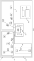
- the M second stage forming drums 210 are moved in the crown structure building line 200 independently and simultaneously with respect to the N first stage forming drums 110 in the carcass structure building line 100, to then convey towards the shaping and assembly station 301.
- N different from M and/or different building cycle times between the carcass structure building line 100 and the crown structure building line 200, it is possible to provide suitable waiting locations for the drums waiting to release the respective crown and carcass structures to the shaping and assembly station 301.
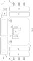
- the axes X, Y, Z, and the rotations about the aforementioned axes X and Y are schematically illustrated in figure 4 .
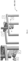
- the second manipulator 400 is capable of operating on the first stage drums 110 in a working area (not illustrated) inside which the second loading/unloading device 320, the third final location P32 and the third intermediate location PI3 of the carcass structure building line 100 are located.
- the first path 220 of the crown structure building line 200 is associated with a storage area 260 adapted to store said semi-finished products.
- the first path 220 of the crown structure building line 200 is associated with feeders 270 adapted to receive the semi-finished products stored by the relative storage area 260 and deposit them on the second stage forming drum 210.
- the transfer devices 282 are anthropomorphic robots, preferably with a robotized arm having at least 6 movement axes.
- the second path 230 of the crown structure building line 200 comprises a first translating support 283 adapted to transfer in sequence, one at a time, said M second stage forming drums 210 from said first intermediate location PI1 to a first seat S1 of the second path 230 of the crown structure building line 200, which is outside of the working area of the first manipulator 500.
- the first path 120 of the carcass structure building line 100 comprises a plurality of work stations (not illustrated). Along the first path 120 of the carcass structure building line 100 one of the N first stage forming drums 110 is moved at a time.
- the first path 120 of the carcass structure building line 100 is associated with a storage area 160 adapted to store said semi-finished products.
- the first path 120 of the carcass structure building line 100 is associated with feeders 170 adapted to receive the semi-finished products stored by the relative storage area 160 and depositing them on the first stage forming drum 110.
Landscapes
- Engineering & Computer Science (AREA)
- Mechanical Engineering (AREA)
- Manufacturing & Machinery (AREA)
- Tyre Moulding (AREA)
- Tires In General (AREA)
- Packaging Of Special Articles (AREA)
Claims (15)
- Verfahren zur Herstellung von Reifen (2) für Fahrzeugräder, umfassend:- Bewegen von M Formtrommeln der zweiten Stufe (210) in einer Kronenstrukturherstellungslinie (200) zum Herstellen von M jeweiligen Kronenstrukturen, wobei M eine ganze Zahl größer oder gleich 1 ist, wobei die Bewegung entlang eines ersten Weges (220) von einer ersten Ausgangsposition (P11) zu einer ersten Endposition (P12) zum Herstellen eines ersten Teils von Komponenten der Kronenstruktur, der mindestens eine Gürtelschicht umfasst, und entlang eines zweiten Weges (230) von einer zweiten Ausgangsposition (P21) über eine erste Zwischenposition (PI1) und eine zweite Zwischenposition (PI2) zu einer zweiten Endposition (P22) zum Herstellen eines zweiten Teils von Komponenten der Kronenstruktur, der zumindest das Laufflächenband umfasst, durchgeführt wird;- Bewegen von N Formtrommeln der ersten Stufe (110) in einer Karkassenstrukturherstellungslinie (100) zum Herstellen von N jeweiligen Karkassenstrukturen, wobei N eine ganze Zahl größer oder gleich 1 ist, von einer dritten Ausgangsposition (P31) über eine dritte Zwischenposition (PI3) zu einer dritten Endposition (P32);- Steuern des Flusses der M Formtrommeln der zweiten Stufe (210), die M jeweilige Kronenstrukturen tragen, die verarbeitet werden, und in den zweiten Weg (220) der Kronenstrukturherstellungslinie (200) eintreten, mithilfe eines ersten Manipulators (500), der für die Übertragung der M Formtrommeln der zweiten Stufe (210), die die M jeweiligen Kronenstrukturen tragen, die verarbeitet werden, von der zweiten Ausgangsposition (P21) zur ersten Zwischenposition (PI1) des zweiten Weges (230) der Kronenstrukturherstellungslinie (200) sorgt;- Steuern des Flusses der M Formtrommeln der zweiten Stufe (210), die in der zweiten Zwischenposition (PI2) ankommen und die M jeweiligen Kronenstrukturen tragen, mithilfe des ersten Manipulators (500), der dafür sorgt, dass:- die Kronenstruktur zu einer ersten Lade-/Entladevorrichtung (310) geliefert wird, die mit einer Formgebungs- und Montagemaschine (300) verbunden ist, und- die jeweilige Formtrommel der zweiten Stufe (210) in diezweite Endposition gebracht wird (P22); und
gekennzeichnet durch- Steuern des Flusses der N Formtrommeln der ersten Stufe (110), die in der dritten Zwischenposition (PI3) ankommen und die N jeweiligen Karkassenstrukturen tragen, mithilfe eines zweiten Manipulators (400), der dafür sorgt, dass:- die Karkassenstruktur zu einer zweiten Lade-/Entladevorrichtung (320) geliefert wird, die mit der Formgebungs- und Montagemaschine (300) verbunden ist, und- die jeweilige Formtrommel der ersten Stufe (110) in die dritte Endposition (P32) gebracht wird;wobei die erste Lade-/Entladevorrichtung (310) und die zweite Lade-/Entladevorrichtung (320) für das jeweilige Verbinden der Kronenstruktur und der Karkassenstruktur auf einer Formgebungstrommel (330) der Formgebungs- und Montagemaschine (300) sorgen, die für die Durchführung der Kreisringformgebung der Karkassenstruktur sorgt und diese mit der Kronenstruktur zusammenfügt. - Verfahren nach Anspruch 1, wobei die Herstellung des ersten Teils von Komponenten der Kronenstruktur durch Ablegen von Halbfertigprodukten durchgeführt wird und/oder die Herstellung des zweiten Teils von Komponenten der Kronenstruktur durch Ablegen von elementaren Halbfertigprodukten durchgeführt wird.
- Verfahren nach einem der vorhergehenden Ansprüche, wobei die Bewegung in der Karkassenstrukturherstellungslinie entlang eines ersten Weges (120), der in der dritten Ausgangsposition (P31) beginnt, zum Herstellen eines ersten Teils von Komponenten der Karkassenstruktur durchgeführt wird, der mindestens eine Karkassenlage umfasst.
- Verfahren nach Anspruch 3, wobei die Bewegung in der Karkassenstrukturherstellungslinie entlang eines zweiten Weges (130), der in der dritten Endposition (P32) endet und durch die dritte Zwischenposition (PI3) verläuft, zum Herstellen eines zweiten Teils von Komponenten der Karkassenstruktur durchgeführt wird, der mindestens eines von einem Anti-Abrieb-Einsatz und einem Abschnitt von Seitenwänden umfasst.
- Verfahren nach Anspruch 3 oder 4, wobei die Bewegung in der Karkassenstrukturherstellungslinie (100) außerdem die Bewegung der N Formtrommeln der ersten Stufe (110) in eine Wulstformungsstation (140) zwischen dem ersten Weg (120) und dem zweiten Weg (130) der Karkassenstrukturherstellungslinie (100) umfasst, um auf den N Formtrommeln der ersten Stufe (110) den Eingriff von axial gegenüberliegenden Enden der jeweiligen Karkassenstruktur, die verarbeitet wird, mit jeweiligen ringförmigen Verankerungsstrukturen durchzuführen.
- Verfahren nach einem der Ansprüche 3 bis 5, wobei die Herstellung des ersten Teils von Komponenten der Karkassenstruktur durch Ablegen von Halbfertigprodukten durchgeführt wird und/oder die Herstellung des zweiten Teils von Komponenten der Karkassenstruktur durch Ablegen von elementaren Halbfertigprodukten durchgeführt.
- Verfahren nach einem der vorhergehenden Ansprüche, wobei:- die erste Endposition (P12) mit der ersten Ausgangsposition (P11) übereinstimmt; und/oder- die zweite Endposition (P22) mit der zweiten Ausgangsposition (P21) übereinstimmt; und/oder- die zweite Endposition (P22) mit der ersten Ausgangsposition (P11) übereinstimmt.
- Anlage (1) zur Herstellung von Reifen (2) für Fahrzeugräder, umfassend:- eine Kronenstrukturherstellungslinie (200) zum Herstellen von M Kronenstrukturen auf M Formtrommeln der zweiten Stufe (210), wobei M eine ganze Zahl größer oder gleich 1 ist, wobei die Kronenstrukturherstellungslinie (200) einen ersten Weg (210), der in einer ersten Ausgangsposition (P11) beginnt und in einer ersten Endposition (P12) endet, zum Herstellen eines ersten Teils von Komponenten der Kronenstruktur, der mindestens eine Gürtelschicht umfasst, und einen zweiten Weg (230), der in einer zweiten Ausgangsposition (P21) beginnt und in einer zweiten Endposition (P22) endet und durch eine erste Zwischenposition (PI1) und eine zweite Zwischenposition (PI2) verläuft, zum Herstellen eines zweiten Teils von Komponenten der Kronenstruktur umfasst, der zumindest das Laufflächenband umfasst;- eine Karkassenstrukturherstellungslinie (100) zum Herstellen von N Karkassenstrukturen auf N Formtrommeln der ersten Stufe (110), wobei N eine ganze Zahl größer oder gleich 1 ist, von einer dritten Ausgangsposition (P31) über eine dritte Zwischenposition (PI3) zu einer dritten Endposition (P32);- eine Formgebungs- und Montagestation (301), die eine erste Lade-/Entladevorrichtung (310), eine zweiten Lade-/Entladevorrichtung (320) und eine Formgebungs- und Montagemaschine (300) mit einer Formgebungstrommel (330) umfasst;- einen ersten Manipulator (500) mit einem Arbeitsbereich, innerhalb dessen die zweite Ausgangsposition (P21), die zweite Endposition (P22), die erste Zwischenposition (PI1) und die zweiten Zwischenposition (PI2) des zweiten Weges (230) der Kronenstrukturherstellungslinie (200) und die erste Lade-/Entladevorrichtung (310) angeordnet sind;- einen zweiten Manipulator (400) mit einem Arbeitsbereich, innerhalb dessen die dritte Endposition (P31) und die dritte Zwischenposition (PI3) der Karkassenstrukturherstellungslinie (100) und die zweite Lade-/Entladevorrichtung (320) angeordnet sind, wobei:- der erste Manipulator (500) sowohl zum Übertragen der M Formtrommeln der zweiten Stufe (210), die M jeweilige Kronenstrukturen tragen, die verarbeitet werden, von der zweiten Ausgangsposition (P21) zur ersten Zwischenposition (PI1) des zweiten Weges (230) der Kronenstrukturherstellungslinie (200) als auch zum Steuern der M Formtrommeln der zweiten Stufe (210), die in der zweiten Zwischenposition (PI2) ankommen und die M jeweiligen Kronenstrukturen tragen, durch Liefern der M Kronenstrukturen zur ersten Lade-/Entladevorrichtung (310) und der jeweiligen Formtrommeln der zweiten Stufe (210) zur zweiten Endposition (P21) konfiguriert ist;- der zweite Manipulator (400) zum Steuern der N Formtrommeln der ersten Stufe (110), die in der dritten Zwischenposition (PI3) ankommen und die N jeweiligen Karkassenstrukturen tragen, durch Liefern der N Karkassenstrukturen zur zweiten Lade-/Entladevorrichtung (320) und der jeweiligen Formtrommeln der ersten Stufe (110) zur dritten Endposition (P31) konfiguriert ist.
- Anlage (1) nach Anspruch 8, wobei der erste Manipulator (500) ein nichtanthropomorpher kartesischer Roboter mit mindestens fünf Freiheitsgraden ist, um die Bewegung der M Formtrommeln der zweiten Stufe entlang dreier kartesischer Achsen (X, Y, Z) und eine Drehung um zwei der kartesischen Achsen (X, Y) zu ermöglichen.
- Anlage (1) nach Anspruch 8 oder 9, wobei der zweite Manipulator (400) ein nichtanthropomorpher kartesischer Roboter mit mindestens fünf Freiheitsgraden ist, um die Bewegung der N Formtrommeln der ersten Stufe entlang dreier kartesischer Achsen (X, Y, Z) und eine Drehung um zwei der kartesischen Achsen (X, Y) zu ermöglichen.
- Anlage (1) nach einem der Ansprüche 8 bis 10, außerdem umfassend einen ersten Verschiebungsträger (283), der zum Übertragen der M Formtrommeln der zweiten Stufe (210) von der ersten Zwischenstation (PH) zu einem ersten Sitz (S1) des zweiten Weges (230) der Kronenstrukturherstellungslinie (200) ausgelegt ist, der sich außerhalb des Arbeitsbereichs des ersten Manipulators (500) befindet.
- Anlage (1) nach einem der Ansprüche 8 bis 11, außerdem umfassend einen zweiten Verschiebungsträger (284), der zum Übertragen der M Formtrommeln der zweiten Stufe (210) von einem zweiten Sitz (S2) des zweiten Weges (230) der Kronenstrukturherstellungslinie (200), der sich außerhalb des Arbeitsbereichs des ersten Manipulators (500) befindet, zur zweiten Zwischenposition (PI2) ausgelegt ist.
- Anlage (1) nach einem der Ansprüche 8 bis 12, außerdem umfassend einen dritten Verschiebungsträger (183), der zum Übertragen der N Formtrommeln der ersten Stufe (110) von einem dritten Sitz (S3) des zweiten Weges (130) der Karkassenstrukturherstellungslinie (100), der sich außerhalb des Arbeitsbereichs des zweiten Manipulators (400) befindet, zur dritten Zwischenposition (PI3) ausgelegt ist.
- Anlage (1) nach einem der Ansprüche 8 bis 13, wobei der erste Weg (220) der Kronenstrukturherstellungslinie (200) eine Mehrzahl von Arbeitsstationen, die der Reihe nach zwischen zwei Enden des ersten Weges (220) angeordnet sind, und einen mobilen Shuttle umfasst, der zum Bewegen der M Formtrommeln der zweiten Stufe (210) zwischen der Mehrzahl von Arbeitsstationen konfiguriert ist.
- Anlage (1) nach Anspruch 14, wobei an mindestens einem der zwei Enden des ersten Weges (220) der Kronenstrukturherstellungslinie (200) eine Lade-/Entladestation vorhanden ist, die mit der ersten Ausgangsposition (P11) übereinstimmt, die wiederum mit der ersten Endposition (P12) übereinstimmt.
Applications Claiming Priority (2)
| Application Number | Priority Date | Filing Date | Title |
|---|---|---|---|
| IT102019000012615A IT201900012615A1 (it) | 2019-07-23 | 2019-07-23 | Metodo ed impianto per confezionare pneumatici per ruote di veicoli |
| PCT/IB2020/056877 WO2021014366A1 (en) | 2019-07-23 | 2020-07-22 | Method and plant for building tyres for vehicle wheels |
Publications (3)
| Publication Number | Publication Date |
|---|---|
| EP4003717A1 EP4003717A1 (de) | 2022-06-01 |
| EP4003717C0 EP4003717C0 (de) | 2023-09-06 |
| EP4003717B1 true EP4003717B1 (de) | 2023-09-06 |
Family
ID=68733475
Family Applications (1)
| Application Number | Title | Priority Date | Filing Date |
|---|---|---|---|
| EP20757666.1A Active EP4003717B1 (de) | 2019-07-23 | 2020-07-22 | Verfahren und anlage zur herstellung von reifen für fahrzeugräder |
Country Status (8)
| Country | Link |
|---|---|
| US (2) | US12049053B2 (de) |
| EP (1) | EP4003717B1 (de) |
| JP (1) | JP7196361B2 (de) |
| KR (1) | KR102468555B1 (de) |
| CN (1) | CN114340882B (de) |
| IT (1) | IT201900012615A1 (de) |
| MX (1) | MX2022000799A (de) |
| WO (1) | WO2021014366A1 (de) |
Families Citing this family (1)
| Publication number | Priority date | Publication date | Assignee | Title |
|---|---|---|---|---|
| IT201900012615A1 (it) | 2019-07-23 | 2021-01-23 | Pirelli | Metodo ed impianto per confezionare pneumatici per ruote di veicoli |
Family Cites Families (20)
| Publication number | Priority date | Publication date | Assignee | Title |
|---|---|---|---|---|
| EP1424182B1 (de) * | 2001-08-10 | 2007-07-04 | Bridgestone Corporation | Reifenvulkanisiersystem |
| US20060169392A1 (en) * | 2002-11-25 | 2006-08-03 | Naruhiro Akiyama | Tire building system, tire manufacturing system having the same, and tire manufacturing method |
| DE10260883B3 (de) * | 2002-12-23 | 2004-07-08 | Yxlon International X-Ray Gmbh | Vorrichtung und Verfahren zur Prüfung von Prüfteilen, insbesondere von Kraftfahrzeugreifen, mittels Röntgenstrahlung |
| WO2006046162A1 (en) | 2004-10-27 | 2006-05-04 | Pirelli Tyre S.P.A. | Method and apparatus for manufacturing layered articles made of elastomeric material |
| ATE544588T1 (de) | 2007-12-21 | 2012-02-15 | Pirelli | Verfahren und anlage zum bau von reifen für fahrzeugräder |
| CN101903163B (zh) | 2007-12-21 | 2014-08-27 | 倍耐力轮胎股份公司 | 用于构造车辆车轮的轮胎的方法和设备 |
| JP4621272B2 (ja) * | 2008-08-04 | 2011-01-26 | 住友ゴム工業株式会社 | 生タイヤ成形装置 |
| CN102300700B (zh) | 2008-12-17 | 2015-09-02 | 倍耐力轮胎股份公司 | 用于构造车轮的生轮胎的处理和设备 |
| EP2516142B1 (de) | 2009-12-22 | 2015-04-08 | Pirelli Tyre S.p.A. | Verfahren und anlage zur herstellung verschiedenen arten von rohreifen für fahrzeugräder |
| JP5641560B2 (ja) | 2010-07-30 | 2014-12-17 | Necエナジーデバイス株式会社 | 二次電池用正極活物質及びそれを使用した二次電池 |
| US20140034220A1 (en) | 2011-04-28 | 2014-02-06 | Gianni Mancini | Process and plant for building tyres for vehicle wheels |
| KR102060516B1 (ko) | 2011-12-23 | 2019-12-30 | 피렐리 타이어 소시에떼 퍼 아찌오니 | 차륜용 타이어 제조를 제어하는 방법, 공정, 및 설비 |
| ITMI20121757A1 (it) * | 2012-10-17 | 2014-04-18 | Pirelli | Metodo e impianto per confezionare pneumatici per ruote di veicoli |
| ITMI20122214A1 (it) * | 2012-12-21 | 2014-06-22 | Pirelli | Metodo e impianto per confezionare pneumatici per ruote di veicoli |
| WO2016075576A1 (en) | 2014-11-14 | 2016-05-19 | Pirelli Tyre S.P.A. | Process and plant for building tyres |
| JP2015098180A (ja) | 2015-02-27 | 2015-05-28 | ピレリ・タイヤ・ソチエタ・ペル・アツィオーニ | 車両の車輪用タイヤを製造するための方法及びプラント |
| WO2017051267A1 (en) * | 2015-09-21 | 2017-03-30 | Pirelli Tyre S.P.A. | Process and plant for building tyres |
| NL2019085B1 (en) | 2017-06-16 | 2018-12-24 | Vmi Holland Bv | Tire building system and method |
| CN111491786B (zh) * | 2017-12-28 | 2021-07-23 | 倍耐力轮胎股份公司 | 用于生产车辆车轮用轮胎的工艺和设备 |
| IT201900012615A1 (it) | 2019-07-23 | 2021-01-23 | Pirelli | Metodo ed impianto per confezionare pneumatici per ruote di veicoli |
-
2019
- 2019-07-23 IT IT102019000012615A patent/IT201900012615A1/it unknown
-
2020
- 2020-07-22 KR KR1020227005588A patent/KR102468555B1/ko active Active
- 2020-07-22 US US17/628,789 patent/US12049053B2/en active Active
- 2020-07-22 JP JP2022503997A patent/JP7196361B2/ja active Active
- 2020-07-22 MX MX2022000799A patent/MX2022000799A/es unknown
- 2020-07-22 CN CN202080062981.6A patent/CN114340882B/zh active Active
- 2020-07-22 WO PCT/IB2020/056877 patent/WO2021014366A1/en not_active Ceased
- 2020-07-22 EP EP20757666.1A patent/EP4003717B1/de active Active
-
2024
- 2024-06-27 US US18/757,376 patent/US12311623B2/en active Active
Also Published As
| Publication number | Publication date |
|---|---|
| IT201900012615A1 (it) | 2021-01-23 |
| US20240343008A1 (en) | 2024-10-17 |
| CN114340882B (zh) | 2022-10-28 |
| EP4003717A1 (de) | 2022-06-01 |
| CN114340882A (zh) | 2022-04-12 |
| US20220274361A1 (en) | 2022-09-01 |
| EP4003717C0 (de) | 2023-09-06 |
| JP2022532448A (ja) | 2022-07-14 |
| US12049053B2 (en) | 2024-07-30 |
| KR20220028152A (ko) | 2022-03-08 |
| BR112022001073A2 (pt) | 2022-03-15 |
| KR102468555B1 (ko) | 2022-11-18 |
| JP7196361B2 (ja) | 2022-12-26 |
| WO2021014366A1 (en) | 2021-01-28 |
| US12311623B2 (en) | 2025-05-27 |
| MX2022000799A (es) | 2022-04-06 |
Similar Documents
| Publication | Publication Date | Title |
|---|---|---|
| EP2387500B1 (de) | Verfahren und anlage zum bau von reifenrohlingen für fahrzeugräder | |
| EP2258541B1 (de) | Verfahren und anlage zur herstellung von fahrzeugreifen | |
| US11198266B2 (en) | Process and plant for building green tyres for vehicle wheels | |
| US12311623B2 (en) | Plant for building tyres for vehicle wheels | |
| EP3732031B1 (de) | Verfahren und anlage zur herstellung von reifen für fahrzeugräder | |
| EP3157739B1 (de) | Verfahren und anlage zur herstellung von rohreifen für fahrzeugräder | |
| US12384126B2 (en) | Method for building belt assemblies for tyres for vehicle wheels | |
| EP4263194B1 (de) | Verfahren zur verwaltung eines verfahrens zur herstellung von reifen für fahrzeugräder und baulinie | |
| EP4076918B1 (de) | Verfahren und anlage zum produzieren von reifen für fahrzeugräder | |
| US20260014766A1 (en) | Plant for producing tyres for vehicle wheels | |
| BR112022001073B1 (pt) | Método e instalação para construir pneus para rodas de veículos |
Legal Events
| Date | Code | Title | Description |
|---|---|---|---|
| STAA | Information on the status of an ep patent application or granted ep patent |
Free format text: STATUS: UNKNOWN |
|
| STAA | Information on the status of an ep patent application or granted ep patent |
Free format text: STATUS: THE INTERNATIONAL PUBLICATION HAS BEEN MADE |
|
| PUAI | Public reference made under article 153(3) epc to a published international application that has entered the european phase |
Free format text: ORIGINAL CODE: 0009012 |
|
| STAA | Information on the status of an ep patent application or granted ep patent |
Free format text: STATUS: REQUEST FOR EXAMINATION WAS MADE |
|
| 17P | Request for examination filed |
Effective date: 20220128 |
|
| AK | Designated contracting states |
Kind code of ref document: A1 Designated state(s): AL AT BE BG CH CY CZ DE DK EE ES FI FR GB GR HR HU IE IS IT LI LT LU LV MC MK MT NL NO PL PT RO RS SE SI SK SM TR |
|
| DAV | Request for validation of the european patent (deleted) | ||
| DAX | Request for extension of the european patent (deleted) | ||
| GRAP | Despatch of communication of intention to grant a patent |
Free format text: ORIGINAL CODE: EPIDOSNIGR1 |
|
| STAA | Information on the status of an ep patent application or granted ep patent |
Free format text: STATUS: GRANT OF PATENT IS INTENDED |
|
| INTG | Intention to grant announced |
Effective date: 20230309 |
|
| GRAS | Grant fee paid |
Free format text: ORIGINAL CODE: EPIDOSNIGR3 |
|
| GRAA | (expected) grant |
Free format text: ORIGINAL CODE: 0009210 |
|
| STAA | Information on the status of an ep patent application or granted ep patent |
Free format text: STATUS: THE PATENT HAS BEEN GRANTED |
|
| AK | Designated contracting states |
Kind code of ref document: B1 Designated state(s): AL AT BE BG CH CY CZ DE DK EE ES FI FR GB GR HR HU IE IS IT LI LT LU LV MC MK MT NL NO PL PT RO RS SE SI SK SM TR |
|
| REG | Reference to a national code |
Ref country code: GB Ref legal event code: FG4D |
|
| REG | Reference to a national code |
Ref country code: CH Ref legal event code: EP |
|
| REG | Reference to a national code |
Ref country code: IE Ref legal event code: FG4D |
|
| REG | Reference to a national code |
Ref country code: DE Ref legal event code: R096 Ref document number: 602020017329 Country of ref document: DE |
|
| U01 | Request for unitary effect filed |
Effective date: 20230913 |
|
| U07 | Unitary effect registered |
Designated state(s): AT BE BG DE DK EE FI FR IT LT LU LV MT NL PT SE SI Effective date: 20230921 |
|
| PG25 | Lapsed in a contracting state [announced via postgrant information from national office to epo] |
Ref country code: GR Free format text: LAPSE BECAUSE OF FAILURE TO SUBMIT A TRANSLATION OF THE DESCRIPTION OR TO PAY THE FEE WITHIN THE PRESCRIBED TIME-LIMIT Effective date: 20231207 |
|
| PG25 | Lapsed in a contracting state [announced via postgrant information from national office to epo] |
Ref country code: RS Free format text: LAPSE BECAUSE OF FAILURE TO SUBMIT A TRANSLATION OF THE DESCRIPTION OR TO PAY THE FEE WITHIN THE PRESCRIBED TIME-LIMIT Effective date: 20230906 Ref country code: NO Free format text: LAPSE BECAUSE OF FAILURE TO SUBMIT A TRANSLATION OF THE DESCRIPTION OR TO PAY THE FEE WITHIN THE PRESCRIBED TIME-LIMIT Effective date: 20231206 Ref country code: HR Free format text: LAPSE BECAUSE OF FAILURE TO SUBMIT A TRANSLATION OF THE DESCRIPTION OR TO PAY THE FEE WITHIN THE PRESCRIBED TIME-LIMIT Effective date: 20230906 Ref country code: GR Free format text: LAPSE BECAUSE OF FAILURE TO SUBMIT A TRANSLATION OF THE DESCRIPTION OR TO PAY THE FEE WITHIN THE PRESCRIBED TIME-LIMIT Effective date: 20231207 |
|
| PG25 | Lapsed in a contracting state [announced via postgrant information from national office to epo] |
Ref country code: IS Free format text: LAPSE BECAUSE OF FAILURE TO SUBMIT A TRANSLATION OF THE DESCRIPTION OR TO PAY THE FEE WITHIN THE PRESCRIBED TIME-LIMIT Effective date: 20240106 |
|
| PG25 | Lapsed in a contracting state [announced via postgrant information from national office to epo] |
Ref country code: ES Free format text: LAPSE BECAUSE OF FAILURE TO SUBMIT A TRANSLATION OF THE DESCRIPTION OR TO PAY THE FEE WITHIN THE PRESCRIBED TIME-LIMIT Effective date: 20230906 |
|
| PG25 | Lapsed in a contracting state [announced via postgrant information from national office to epo] |
Ref country code: SM Free format text: LAPSE BECAUSE OF FAILURE TO SUBMIT A TRANSLATION OF THE DESCRIPTION OR TO PAY THE FEE WITHIN THE PRESCRIBED TIME-LIMIT Effective date: 20230906 Ref country code: IS Free format text: LAPSE BECAUSE OF FAILURE TO SUBMIT A TRANSLATION OF THE DESCRIPTION OR TO PAY THE FEE WITHIN THE PRESCRIBED TIME-LIMIT Effective date: 20240106 Ref country code: ES Free format text: LAPSE BECAUSE OF FAILURE TO SUBMIT A TRANSLATION OF THE DESCRIPTION OR TO PAY THE FEE WITHIN THE PRESCRIBED TIME-LIMIT Effective date: 20230906 Ref country code: CZ Free format text: LAPSE BECAUSE OF FAILURE TO SUBMIT A TRANSLATION OF THE DESCRIPTION OR TO PAY THE FEE WITHIN THE PRESCRIBED TIME-LIMIT Effective date: 20230906 Ref country code: SK Free format text: LAPSE BECAUSE OF FAILURE TO SUBMIT A TRANSLATION OF THE DESCRIPTION OR TO PAY THE FEE WITHIN THE PRESCRIBED TIME-LIMIT Effective date: 20230906 |
|
| PG25 | Lapsed in a contracting state [announced via postgrant information from national office to epo] |
Ref country code: PL Free format text: LAPSE BECAUSE OF FAILURE TO SUBMIT A TRANSLATION OF THE DESCRIPTION OR TO PAY THE FEE WITHIN THE PRESCRIBED TIME-LIMIT Effective date: 20230906 |
|
| REG | Reference to a national code |
Ref country code: DE Ref legal event code: R097 Ref document number: 602020017329 Country of ref document: DE |
|
| PLBE | No opposition filed within time limit |
Free format text: ORIGINAL CODE: 0009261 |
|
| STAA | Information on the status of an ep patent application or granted ep patent |
Free format text: STATUS: NO OPPOSITION FILED WITHIN TIME LIMIT |
|
| 26N | No opposition filed |
Effective date: 20240607 |
|
| U20 | Renewal fee for the european patent with unitary effect paid |
Year of fee payment: 5 Effective date: 20240729 |
|
| PG25 | Lapsed in a contracting state [announced via postgrant information from national office to epo] |
Ref country code: MC Free format text: LAPSE BECAUSE OF FAILURE TO SUBMIT A TRANSLATION OF THE DESCRIPTION OR TO PAY THE FEE WITHIN THE PRESCRIBED TIME-LIMIT Effective date: 20230906 |
|
| REG | Reference to a national code |
Ref country code: CH Ref legal event code: PL |
|
| PG25 | Lapsed in a contracting state [announced via postgrant information from national office to epo] |
Ref country code: CH Free format text: LAPSE BECAUSE OF NON-PAYMENT OF DUE FEES Effective date: 20240731 |
|
| PG25 | Lapsed in a contracting state [announced via postgrant information from national office to epo] |
Ref country code: IE Free format text: LAPSE BECAUSE OF NON-PAYMENT OF DUE FEES Effective date: 20240722 |
|
| U20 | Renewal fee for the european patent with unitary effect paid |
Year of fee payment: 6 Effective date: 20250728 |
|
| PGFP | Annual fee paid to national office [announced via postgrant information from national office to epo] |
Ref country code: GB Payment date: 20250728 Year of fee payment: 6 |
|
| PGFP | Annual fee paid to national office [announced via postgrant information from national office to epo] |
Ref country code: RO Payment date: 20250707 Year of fee payment: 6 |
|
| PG25 | Lapsed in a contracting state [announced via postgrant information from national office to epo] |
Ref country code: CY Free format text: LAPSE BECAUSE OF FAILURE TO SUBMIT A TRANSLATION OF THE DESCRIPTION OR TO PAY THE FEE WITHIN THE PRESCRIBED TIME-LIMIT; INVALID AB INITIO Effective date: 20200722 |
|
| PG25 | Lapsed in a contracting state [announced via postgrant information from national office to epo] |
Ref country code: HU Free format text: LAPSE BECAUSE OF FAILURE TO SUBMIT A TRANSLATION OF THE DESCRIPTION OR TO PAY THE FEE WITHIN THE PRESCRIBED TIME-LIMIT; INVALID AB INITIO Effective date: 20200722 |