EP4003768B1 - Steuerung der aufladung einer batterie eines fahrzeuges im leerlauf - Google Patents
Steuerung der aufladung einer batterie eines fahrzeuges im leerlauf Download PDFInfo
- Publication number
- EP4003768B1 EP4003768B1 EP20747025.3A EP20747025A EP4003768B1 EP 4003768 B1 EP4003768 B1 EP 4003768B1 EP 20747025 A EP20747025 A EP 20747025A EP 4003768 B1 EP4003768 B1 EP 4003768B1
- Authority
- EP
- European Patent Office
- Prior art keywords
- coupled
- driving machine
- torque
- battery
- gearbox
- Prior art date
- Legal status (The legal status is an assumption and is not a legal conclusion. Google has not performed a legal analysis and makes no representation as to the accuracy of the status listed.)
- Active
Links
Images


Classifications
-
- B—PERFORMING OPERATIONS; TRANSPORTING
- B60—VEHICLES IN GENERAL
- B60W—CONJOINT CONTROL OF VEHICLE SUB-UNITS OF DIFFERENT TYPE OR DIFFERENT FUNCTION; CONTROL SYSTEMS SPECIALLY ADAPTED FOR HYBRID VEHICLES; ROAD VEHICLE DRIVE CONTROL SYSTEMS FOR PURPOSES NOT RELATED TO THE CONTROL OF A PARTICULAR SUB-UNIT
- B60W20/00—Control systems specially adapted for hybrid vehicles
- B60W20/10—Controlling the power contribution of each of the prime movers to meet required power demand
- B60W20/13—Controlling the power contribution of each of the prime movers to meet required power demand in order to stay within battery power input or output limits; in order to prevent overcharging or battery depletion
-
- B—PERFORMING OPERATIONS; TRANSPORTING
- B60—VEHICLES IN GENERAL
- B60K—ARRANGEMENT OR MOUNTING OF PROPULSION UNITS OR OF TRANSMISSIONS IN VEHICLES; ARRANGEMENT OR MOUNTING OF PLURAL DIVERSE PRIME-MOVERS IN VEHICLES; AUXILIARY DRIVES FOR VEHICLES; INSTRUMENTATION OR DASHBOARDS FOR VEHICLES; ARRANGEMENTS IN CONNECTION WITH COOLING, AIR INTAKE, GAS EXHAUST OR FUEL SUPPLY OF PROPULSION UNITS IN VEHICLES
- B60K6/00—Arrangement or mounting of plural diverse prime-movers for mutual or common propulsion, e.g. hybrid propulsion systems comprising electric motors and internal combustion engines
- B60K6/20—Arrangement or mounting of plural diverse prime-movers for mutual or common propulsion, e.g. hybrid propulsion systems comprising electric motors and internal combustion engines the prime-movers consisting of electric motors and internal combustion engines, e.g. HEVs
- B60K6/42—Arrangement or mounting of plural diverse prime-movers for mutual or common propulsion, e.g. hybrid propulsion systems comprising electric motors and internal combustion engines the prime-movers consisting of electric motors and internal combustion engines, e.g. HEVs characterised by the architecture of the hybrid electric vehicle
- B60K6/48—Parallel type
-
- B—PERFORMING OPERATIONS; TRANSPORTING
- B60—VEHICLES IN GENERAL
- B60W—CONJOINT CONTROL OF VEHICLE SUB-UNITS OF DIFFERENT TYPE OR DIFFERENT FUNCTION; CONTROL SYSTEMS SPECIALLY ADAPTED FOR HYBRID VEHICLES; ROAD VEHICLE DRIVE CONTROL SYSTEMS FOR PURPOSES NOT RELATED TO THE CONTROL OF A PARTICULAR SUB-UNIT
- B60W10/00—Conjoint control of vehicle sub-units of different type or different function
- B60W10/04—Conjoint control of vehicle sub-units of different type or different function including control of propulsion units
- B60W10/06—Conjoint control of vehicle sub-units of different type or different function including control of propulsion units including control of combustion engines
-
- B—PERFORMING OPERATIONS; TRANSPORTING
- B60—VEHICLES IN GENERAL
- B60W—CONJOINT CONTROL OF VEHICLE SUB-UNITS OF DIFFERENT TYPE OR DIFFERENT FUNCTION; CONTROL SYSTEMS SPECIALLY ADAPTED FOR HYBRID VEHICLES; ROAD VEHICLE DRIVE CONTROL SYSTEMS FOR PURPOSES NOT RELATED TO THE CONTROL OF A PARTICULAR SUB-UNIT
- B60W10/00—Conjoint control of vehicle sub-units of different type or different function
- B60W10/04—Conjoint control of vehicle sub-units of different type or different function including control of propulsion units
- B60W10/08—Conjoint control of vehicle sub-units of different type or different function including control of propulsion units including control of electric propulsion units, e.g. motors or generators
-
- B—PERFORMING OPERATIONS; TRANSPORTING
- B60—VEHICLES IN GENERAL
- B60W—CONJOINT CONTROL OF VEHICLE SUB-UNITS OF DIFFERENT TYPE OR DIFFERENT FUNCTION; CONTROL SYSTEMS SPECIALLY ADAPTED FOR HYBRID VEHICLES; ROAD VEHICLE DRIVE CONTROL SYSTEMS FOR PURPOSES NOT RELATED TO THE CONTROL OF A PARTICULAR SUB-UNIT
- B60W30/00—Purposes of road vehicle drive control systems not related to the control of a particular sub-unit, e.g. of systems using conjoint control of vehicle sub-units
- B60W30/18—Propelling the vehicle
- B60W30/18009—Propelling the vehicle related to particular drive situations
- B60W30/18054—Propelling the vehicle related to particular drive situations at stand still, e.g. engine in idling state
-
- B—PERFORMING OPERATIONS; TRANSPORTING
- B60—VEHICLES IN GENERAL
- B60K—ARRANGEMENT OR MOUNTING OF PROPULSION UNITS OR OF TRANSMISSIONS IN VEHICLES; ARRANGEMENT OR MOUNTING OF PLURAL DIVERSE PRIME-MOVERS IN VEHICLES; AUXILIARY DRIVES FOR VEHICLES; INSTRUMENTATION OR DASHBOARDS FOR VEHICLES; ARRANGEMENTS IN CONNECTION WITH COOLING, AIR INTAKE, GAS EXHAUST OR FUEL SUPPLY OF PROPULSION UNITS IN VEHICLES
- B60K6/00—Arrangement or mounting of plural diverse prime-movers for mutual or common propulsion, e.g. hybrid propulsion systems comprising electric motors and internal combustion engines
- B60K6/20—Arrangement or mounting of plural diverse prime-movers for mutual or common propulsion, e.g. hybrid propulsion systems comprising electric motors and internal combustion engines the prime-movers consisting of electric motors and internal combustion engines, e.g. HEVs
- B60K6/42—Arrangement or mounting of plural diverse prime-movers for mutual or common propulsion, e.g. hybrid propulsion systems comprising electric motors and internal combustion engines the prime-movers consisting of electric motors and internal combustion engines, e.g. HEVs characterised by the architecture of the hybrid electric vehicle
- B60K6/48—Parallel type
- B60K2006/4825—Electric machine connected or connectable to gearbox input shaft
-
- B—PERFORMING OPERATIONS; TRANSPORTING
- B60—VEHICLES IN GENERAL
- B60W—CONJOINT CONTROL OF VEHICLE SUB-UNITS OF DIFFERENT TYPE OR DIFFERENT FUNCTION; CONTROL SYSTEMS SPECIALLY ADAPTED FOR HYBRID VEHICLES; ROAD VEHICLE DRIVE CONTROL SYSTEMS FOR PURPOSES NOT RELATED TO THE CONTROL OF A PARTICULAR SUB-UNIT
- B60W50/00—Details of control systems for road vehicle drive control not related to the control of a particular sub-unit, e.g. process diagnostic or vehicle driver interfaces
- B60W2050/0001—Details of the control system
- B60W2050/0019—Control system elements or transfer functions
- B60W2050/0026—Lookup tables or parameter maps
-
- B—PERFORMING OPERATIONS; TRANSPORTING
- B60—VEHICLES IN GENERAL
- B60W—CONJOINT CONTROL OF VEHICLE SUB-UNITS OF DIFFERENT TYPE OR DIFFERENT FUNCTION; CONTROL SYSTEMS SPECIALLY ADAPTED FOR HYBRID VEHICLES; ROAD VEHICLE DRIVE CONTROL SYSTEMS FOR PURPOSES NOT RELATED TO THE CONTROL OF A PARTICULAR SUB-UNIT
- B60W2510/00—Input parameters relating to a particular sub-units
- B60W2510/02—Clutches
- B60W2510/0241—Clutch slip, i.e. difference between input and output speeds
-
- B—PERFORMING OPERATIONS; TRANSPORTING
- B60—VEHICLES IN GENERAL
- B60W—CONJOINT CONTROL OF VEHICLE SUB-UNITS OF DIFFERENT TYPE OR DIFFERENT FUNCTION; CONTROL SYSTEMS SPECIALLY ADAPTED FOR HYBRID VEHICLES; ROAD VEHICLE DRIVE CONTROL SYSTEMS FOR PURPOSES NOT RELATED TO THE CONTROL OF A PARTICULAR SUB-UNIT
- B60W2510/00—Input parameters relating to a particular sub-units
- B60W2510/02—Clutches
- B60W2510/0275—Clutch torque
-
- B—PERFORMING OPERATIONS; TRANSPORTING
- B60—VEHICLES IN GENERAL
- B60W—CONJOINT CONTROL OF VEHICLE SUB-UNITS OF DIFFERENT TYPE OR DIFFERENT FUNCTION; CONTROL SYSTEMS SPECIALLY ADAPTED FOR HYBRID VEHICLES; ROAD VEHICLE DRIVE CONTROL SYSTEMS FOR PURPOSES NOT RELATED TO THE CONTROL OF A PARTICULAR SUB-UNIT
- B60W2510/00—Input parameters relating to a particular sub-units
- B60W2510/06—Combustion engines, Gas turbines
- B60W2510/0638—Engine speed
-
- B—PERFORMING OPERATIONS; TRANSPORTING
- B60—VEHICLES IN GENERAL
- B60W—CONJOINT CONTROL OF VEHICLE SUB-UNITS OF DIFFERENT TYPE OR DIFFERENT FUNCTION; CONTROL SYSTEMS SPECIALLY ADAPTED FOR HYBRID VEHICLES; ROAD VEHICLE DRIVE CONTROL SYSTEMS FOR PURPOSES NOT RELATED TO THE CONTROL OF A PARTICULAR SUB-UNIT
- B60W2510/00—Input parameters relating to a particular sub-units
- B60W2510/08—Electric propulsion units
- B60W2510/081—Speed
-
- B—PERFORMING OPERATIONS; TRANSPORTING
- B60—VEHICLES IN GENERAL
- B60W—CONJOINT CONTROL OF VEHICLE SUB-UNITS OF DIFFERENT TYPE OR DIFFERENT FUNCTION; CONTROL SYSTEMS SPECIALLY ADAPTED FOR HYBRID VEHICLES; ROAD VEHICLE DRIVE CONTROL SYSTEMS FOR PURPOSES NOT RELATED TO THE CONTROL OF A PARTICULAR SUB-UNIT
- B60W2510/00—Input parameters relating to a particular sub-units
- B60W2510/10—Change speed gearings
- B60W2510/1005—Transmission ratio engaged
- B60W2510/101—Transmission neutral state
-
- B—PERFORMING OPERATIONS; TRANSPORTING
- B60—VEHICLES IN GENERAL
- B60W—CONJOINT CONTROL OF VEHICLE SUB-UNITS OF DIFFERENT TYPE OR DIFFERENT FUNCTION; CONTROL SYSTEMS SPECIALLY ADAPTED FOR HYBRID VEHICLES; ROAD VEHICLE DRIVE CONTROL SYSTEMS FOR PURPOSES NOT RELATED TO THE CONTROL OF A PARTICULAR SUB-UNIT
- B60W2520/00—Input parameters relating to overall vehicle dynamics
- B60W2520/10—Longitudinal speed
-
- B—PERFORMING OPERATIONS; TRANSPORTING
- B60—VEHICLES IN GENERAL
- B60W—CONJOINT CONTROL OF VEHICLE SUB-UNITS OF DIFFERENT TYPE OR DIFFERENT FUNCTION; CONTROL SYSTEMS SPECIALLY ADAPTED FOR HYBRID VEHICLES; ROAD VEHICLE DRIVE CONTROL SYSTEMS FOR PURPOSES NOT RELATED TO THE CONTROL OF A PARTICULAR SUB-UNIT
- B60W2710/00—Output or target parameters relating to a particular sub-units
- B60W2710/06—Combustion engines, Gas turbines
- B60W2710/0666—Engine torque
-
- Y—GENERAL TAGGING OF NEW TECHNOLOGICAL DEVELOPMENTS; GENERAL TAGGING OF CROSS-SECTIONAL TECHNOLOGIES SPANNING OVER SEVERAL SECTIONS OF THE IPC; TECHNICAL SUBJECTS COVERED BY FORMER USPC CROSS-REFERENCE ART COLLECTIONS [XRACs] AND DIGESTS
- Y02—TECHNOLOGIES OR APPLICATIONS FOR MITIGATION OR ADAPTATION AGAINST CLIMATE CHANGE
- Y02T—CLIMATE CHANGE MITIGATION TECHNOLOGIES RELATED TO TRANSPORTATION
- Y02T10/00—Road transport of goods or passengers
- Y02T10/60—Other road transportation technologies with climate change mitigation effect
- Y02T10/62—Hybrid vehicles
Definitions
- the present invention claims the priority of the application French 1908319 filed on 23.07.2019 .
- the invention relates to vehicles comprising first and second driving machines coupled via a clutch, and more precisely the control of the recharging of the battery which is coupled to the second driving machine in these vehicles.
- Some vehicles include a transmission chain comprising a first driving machine, such as for example a heat engine or an electric or hydraulic machine, coupled to a clutch also coupled to a second driving machine, electric and also coupled to a rechargeable battery and to a primary shaft of a gearbox coupled to a train.
- a first driving machine such as for example a heat engine or an electric or hydraulic machine
- a clutch also coupled to a second driving machine, electric and also coupled to a rechargeable battery and to a primary shaft of a gearbox coupled to a train.
- the first and second motive machines are part of what is commonly referred to as the powertrain (or GMP).
- the term "driving machine” means a machine arranged so as to supply or recover torque to move a vehicle, either alone or in addition to at least one other thermal or non-thermal driving machine.
- a non-thermal driving machine can, for example, be an electric machine (or motor), a hydraulic machine, a pneumatic (or compressed air) machine, or a flywheel.
- a thermal motor machine can, for example, be a thermal engine.
- the second motor machine it is common for the second motor machine to use a speed regulating function in order to oppose the first motor machine and thus stabilize the optimum speed.
- the speed of the first driving machine (curve c1) is linked to the speed of the second driving machine (curve c2) because the clutch is closed (clutch torque greater than the torque of the first driving machine).
- the first driving machine provides a positive torque (curve c3) while the second driving machine provides the same torque but of opposite sign (curve c4) in order to maintain the primary shaft speed (which is here equal to the second speed) constant and equal to the primary shaft speed setpoint (curve c5).
- the object of the invention is therefore in particular to improve the situation.
- the invention also proposes a computer program product comprising a set of instructions which, when it is executed by processing means, is suitable for implementing a control method of the type from that presented above for controlling a charging of a battery of a vehicle comprising a first driving machine coupled to a clutch also coupled to a second driving machine, electric and also coupled to this battery and to a primary shaft of a gearbox which is coupled to a train.
- the invention also proposes a control device making it possible to control a recharging of a battery of a vehicle according to claim 9.
- the invention also proposes a vehicle, possibly of the automotive type, and comprising, on the one hand, a first driving machine coupled to a clutch also coupled to a second driving machine, electric and also coupled to a rechargeable battery and to a primary shaft of a gearbox coupled to a train, and, on the other hand, a control device of the type presented above.
- the first driving machine can be a heat engine or an electric machine supplied with electrical energy by the battery.
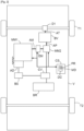
- the object of the invention is in particular to propose a control method, and an associated control device DC, intended to allow the control of the recharging of a battery BR of a vehicle V comprising a first driving machine MM1 coupled to a clutch EM, also coupled to a second driving machine MM2, electric and also coupled to this battery BR and to a primary shaft AP of a gearbox BV coupled to a train T1.
- the vehicle V is of the automobile type. This is for example a car, as illustrated without limitation in the picture 2 . But the invention is not limited to this type of vehicle. It relates in fact to any type of vehicle comprising a transmission chain comprising at least a first driving machine, thermal or non-thermal and coupled to a clutch also coupled to a second driving machine, electric and also coupled to a primary shaft of a gearbox coupled to a train. Therefore, the invention relates not only to land vehicles, but also to ships and aircraft.
- a non-thermal driving machine can, for example, be an electric machine (or motor), a hydraulic machine, a pneumatic (or compressed air) machine, or a flywheel.
- a thermal motor machine can, for example, be a thermal engine.
- a vehicle V comprising a transmission chain, a supervision computer CS capable of supervising (or managing) the operation of the transmission chain, and a control device DC according to the invention.
- the transmission chain here comprises, in particular, a first driving machine MM1, a driving shaft AM, a clutch EM, a second electric driving machine MM2, a gearbox BV, a rechargeable battery BR and a transmission shaft AT.
- the first prime mover MM1 is thermal. This is for example a heat engine. But the invention is not limited to this type of first driving machine. Indeed, the first driving machine MM1 can be thermal or non-thermal (and in particular electric).
- This first prime mover MM1 (here a heat engine) comprises a crankshaft (not shown) which is fixedly attached to the motor shaft AM in order to drive the latter (AM) in rotation. Furthermore, this first driving machine MM1 is intended to provide a first torque for at least a first train T1 (here of wheels), via the clutch EM, the second driving machine MM2, and the gearbox BV.
- this first train T1 is located at the front of the vehicle V, and coupled to the transmission shaft AT, preferably, and as illustrated, via a differential (here front) D1. But in a variant this first train T1 could be located at the rear of the vehicle V.
- the clutch EM is responsible for coupling/decoupling the motor shaft AM (coupled to the first motor machine MM1) to/from the second motor machine MM2, on the order of the supervision computer CS, in order to communicate a second torque from the first torque produced by the first motor machine MM1.
- This clutch EM can be of any type as long as it can assume at least a first state (coupled or engaged or even closed) in which it ensures maximum coupling between the first MM1 and second MM2 driving machines, a second state (uncoupled or disengaged or even open) in which it completely decouples the first driving machine MM1 from the second driving machine MM2, and a third sliding state.
- the second driving machine MM2 (electric) is coupled to the battery BR in order to be supplied with energy or to supply the latter (BR) with energy. It is also coupled to the output of the clutch EM, to receive the second torque, and to the primary shaft AP of the gearbox BV, to supply it with a third torque.
- the BR battery is of the low voltage type (typically 220 V for illustrative purposes). But it could be medium voltage or high voltage.
- the primary shaft AP of the gearbox BV is intended to receive the third torque from the second prime mover MM2.
- the gearbox BV also comprises at least one secondary shaft (not shown) intended to receive the third torque via the primary shaft AP in order to communicate it to the transmission shaft AT to which it is coupled and which is coupled indirectly to the driving wheels (here front) of the vehicle V via the differential D1.
- the transmission chain may also include a starter or an alternator AD coupled to the first driving machine MM1 and responsible for launching the latter (MM1) in order to allow it to start.
- This launch is done using electrical energy which is, for example and as illustrated without limitation, stored in a service battery BS.
- the latter (BS) can be arranged in the form of a battery of the very low voltage type (for example 12 V, 24 V or 48 V), and can also, for example, supply an on-board network to which electrical equipment of the vehicle V is connected.
- the service battery BS can, as illustrated without limitation, be coupled to the battery BR and to the second driving machine MM2 via a converter CV of the DC/DC type, in order to be able to be recharged.
- the operations of the first MM1 and second MM2 driving machines and of the clutch EM can be controlled by the supervision computer CS.
- the transmission chain could also include a third non-thermal driving machine in addition to its first MM1 and second MM2 driving machines.
- this third non-thermal driving machine is responsible for providing torque for a second train T2 of the vehicle V, for example located at the rear, from the energy stored in the battery BR. It then operates either alone or in addition to the first driving machine MM1 and/or the second driving machine MM2, depending on the commands supplied by the supervision computer CS.
- control device DC is part of the supervision computer CS. But this is not mandatory. This control device DC could in fact be an item of equipment coupled to the supervision computer CS, directly or indirectly.
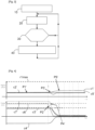
- the control method comprises a step 10-40 which begins in a sub-step 10 when it is decided (internally (for example by the supervision CS) or by the driver) to carry out a charging phase of the battery BR while the gearbox BV is in a neutral (or neutral) position.
- one begins by monitoring in a sub-step 20 a difference er between the first and second speeds respectively of the first MM1 and second MM2 driving machines.
- step 10-40 (of the method) the first torque which is produced by the first prime mover MM1 as a function of this deviation er.
- first driving machine MM1 provides a first positive torque (curve c3') while the second driving machine MM2 provides a third torque (curve c4') slightly lower than the first torque but of opposite sign in order to maintain the speed of the primary shaft AP (which is here equal to the third speed) constant and equal to the speed setpoint of the primary shaft (curve c5').
- second part referenced P2' an unwanted drop in the second clutch torque is observed (curve c6'), which is automatically detected by the control device DC which monitors the difference er between the first and second speeds.
- the first prime mover MM1 is no longer retained by the clutch EM and therefore its first speed (curve c1') begins to increase while the second speed of the second driving machine MM2 (curve c2') begins to decrease (because the latter (MM2) applies a negative torque at the start of the opening of the clutch EM), which causes an increase in the difference er in a third part referenced P3'.
- the control device DC then immediately decides to reduce the first torque produced by the first prime mover MM1 (curve c3') in a fourth part referenced P4'.
- the invention when the first prime mover MM1 is a heat engine, the invention also makes it possible to avoid performing injection cut-offs and therefore the generation of noise and vibrations (as happens in a vehicle of the prior art).
- At least two embodiments can be envisaged for carrying out the control of the operation of the first prime mover MM1 as a function of the deviation er.
- step 10-40 of the method on can reduce the first torque produced by the first prime mover MM1 as a function of the difference er between the first and second speeds.
- step 10-40 of the method one (the DC control device) can impose on the first prime mover MM1 to produce a first chosen limiting torque when the difference er between the first and second speeds becomes greater than a threshold sr (i.e. er > sr).
- a threshold sr i.e. er > sr.
- the control device DC If the deviation er is less than the threshold sr, the control device DC returns to perform sub-step 20. On the other hand, if the deviation er is greater than the threshold s2, the control device DC performs a sub-step 40 in which it reduces the first torque by imposing a chosen limiting torque (curve c7' of the figure 4 ).
- the first limiting torque imposed can, for example, be either predefined (and therefore constant regardless of the value of the deviation er), or chosen as a function of the deviation er.
- the threshold sr can be chosen as a function of the second speed or of the speed setpoint of the primary shaft AP.
- step 10-40 of the method one (the control device DC) can determine a first limiting torque for the first motor machine MM1 according to stored data which establishes a correspondence between differences between the first and second speeds and first limiting torques.
- These data (stored in the control device DC) can constitute what those skilled in the art frequently call a map.
- one can reduce the first speed of the first prime mover MM1 as a function of the difference er between the first and second speeds.
- the control device DC can reduce the first speed of the first prime mover MM1 as a function of the difference er between the first and second speeds.
- the control device DC it is possible to define a limiting torque value dependent on the difference er between the first and second speeds.
- the limiting torque will be configured so that it decreases and can completely cancel out when the difference in speed er increases. This definitely results in a stabilization of the speed of the first prime mover MM1.
- This second embodiment consumes more computing resources than the first and, moreover, takes longer to configure.
- the DC control device may also comprise, in addition to its random access memory MD and its processor PR, a mass memory MM, in particular for storing the values of the first and second speeds and the various torque and speed setpoints, and intermediate data involved in all its calculations and processing.
- this DC control device can also comprise an input interface IE for receiving at least the values of the first and second speeds and of the various torque and speed setpoints to use them in calculations or processing, possibly after having them shaped and/or demodulated and/or amplified, in a manner known per se, by means of a digital signal processor PR′.
- this control device DC can also comprise an output interface IS, in particular for delivering orders, commands and messages (at least for the supervision computer CS).
- the invention also proposes a computer program product (or computer program) comprising a set of instructions which, when it is executed by processing means of the electronic circuit (or hardware) type, such as for example the processor PR, is suitable for implementing the control method described above for controlling the charging of the battery BR of the vehicle V.
- control method can be implemented by a plurality of digital signal processors, random access memory, mass memory, input interface, output interface.
Landscapes
- Engineering & Computer Science (AREA)
- Chemical & Material Sciences (AREA)
- Combustion & Propulsion (AREA)
- Transportation (AREA)
- Mechanical Engineering (AREA)
- Automation & Control Theory (AREA)
- Electric Propulsion And Braking For Vehicles (AREA)
- Hybrid Electric Vehicles (AREA)
- Control Of Transmission Device (AREA)
Claims (10)
- Steuerverfahren für ein Fahrzeug (V), das eine erste Antriebsmaschine (MM1) umfasst, die mit einer Kupplung (EM) gekoppelt ist, die auch mit einer zweiten Antriebsmaschine (MM2) gekoppelt ist, elektrisch und auch mit einer wiederaufladbaren Batterie (BR) und einer primären Welle gekoppelt (AP) eines an einen Zug gekoppelten Getriebes (BV), wobei dieses Verfahren einen Schritt (10-40) umfasst, in dem, wenn sich das Getriebe (BV) in einer neutralen Position befindet und sich die Batterie (BR ) in einer Wiederaufladephase befindet, ein von der ersten Antriebsmaschine (MM1) erzeugtes erstes Drehmoment überwacht wird, dadurch gekennzeichnet, dass zusätzlich eine Differenz zwischen ersten bzw. zweiten Drehzahlen der ersten (MM1) und zweiten (MM2) Antriebsmaschine und dieses erste Drehmoment überwacht wird die von der ersten Antriebsmaschine (MM1) erzeugt wird, wird als Funktion dieser Differenz gesteuert.
- Verfahren nach Anspruch 1, dadurch gekennzeichnet, dass in Schritt (10-40) das von der ersten Antriebsmaschine (MM1) erzeugte erste Drehmoment als Funktion der Differenz zwischen der ersten und der zweiten Geschwindigkeit reduziert wird.
- Verfahren nach Anspruch 2, dadurch gekennzeichnet, dass in Schritt (10-40) ein erstes Grenzdrehmoment für die erste Antriebsmaschine (MM1) als eine Funktion gespeicherter Daten bestimmt wird, die eine Entsprechung zwischen Abweichungen zwischen der ersten und der zweiten Motordrehzahl herstellen die ersten limitierenden Paare.
- Verfahren nach Anspruch 2, dadurch gekennzeichnet, dass in Schritt (10-40) die erste Antriebsmaschine (MM1) ein erstes gewähltes Grenzdrehmoment erzeugen muss, wenn die Differenz zwischen der ersten und der zweiten Geschwindigkeit größer als ein Schwellenwert wird.
- Verfahren nach Anspruch 4, dadurch gekennzeichnet, dass das erste auferlegte Grenzdrehmoment vordefiniert ist.
- Verfahren nach Anspruch 4, dadurch gekennzeichnet, dass das erste auferlegte Grenzdrehmoment in Abhängigkeit von der Abweichung gewählt wird.
- Verfahren nach Anspruch 1, dadurch gekennzeichnet, dass in Schritt (10-40) die erste Geschwindigkeit der ersten Antriebsmaschine (MM1) als Funktion der Differenz zwischen der ersten und der zweiten Geschwindigkeit reduziert wird.
- Computerprogrammprodukt, umfassend einen Satz von Anweisungen, die, wenn sie von Verarbeitungsmitteln ausgeführt werden, in der Lage sind, das Steuerverfahren nach einem der vorangehenden Ansprüche zum Steuern eines Wiederaufladens einer Batterie (BR) eines Fahrzeugs (V) zu implementieren, umfassend a erste Antriebsmaschine (MM1), die mit einer Kupplung (EM) gekoppelt ist, die auch mit einer zweiten Antriebsmaschine (MM2) gekoppelt ist, elektrisch und auch mit der Batterie (BR) und mit einer Primärwelle (AP) eines Getriebes (BV) gekoppelt ist ein Zug.
- Steuervorrichtung (DC) für ein Fahrzeug (V), umfassend eine erste Antriebsmaschine (MM1), die mit einer Kupplung (EM) gekoppelt ist, die auch mit einer zweiten Antriebsmaschine (MM2) gekoppelt ist, elektrisch und auch gekoppelt mit einer wiederaufladbaren Batterie (BR) und an eine Primärwelle (AP) eines Getriebes (BV), das mit einem Zug gekoppelt ist und mindestens einen Prozessor (PR) und mindestens einen Speicher (MD) umfasst, die angeordnet sind, um die Operationen durchzuführen, die bestehen, wenn sich das Getriebe (BV) in a befindet Neutralstellung befindet und sich die Batterie (BR) in einer Wiederaufladephase befindet, um ein von der ersten Antriebsmaschine (MM1) erzeugtes erstes Drehmoment zu steuern, dadurch gekennzeichnet, dass sie ferner angeordnet ist, um die Operationen durchzuführen, die ferner darin bestehen, eine Differenz zwischen der ersten und der zweiten zu überwachen Drehzahlen der ersten (MM1) bzw. zweiten (MM2) Antriebsmaschine, und beim Steuern dieses ersten Drehmoments, das von der ersten Antriebsmaschine (MM1) erzeugt wird, als eine Funktion der Differenz.
- Fahrzeug (V), umfassend eine erste Antriebsmaschine (MM1), die mit einer Kupplung (EM) gekoppelt ist, die auch mit einer zweiten Antriebsmaschine (MM2) gekoppelt ist, elektrisch und auch gekoppelt mit einer wiederaufladbaren Batterie (BR) und mit einer Primärwelle (AP) d 'ein an einen Zug gekoppeltes Schaltgetriebe (BV), dadurch gekennzeichnet, dass es ferner eine Steuervorrichtung (DC) nach Anspruch 9 umfasst.
Applications Claiming Priority (2)
| Application Number | Priority Date | Filing Date | Title |
|---|---|---|---|
| FR1908319A FR3099112B1 (fr) | 2019-07-23 | 2019-07-23 | Contrôle des recharges d’une batterie d’un véhicule dont la boîte de vitesses est au neutre |
| PCT/FR2020/051090 WO2021014060A1 (fr) | 2019-07-23 | 2020-06-23 | Contrôle des recharges d'une batterie d'un véhicule dont la boîte de vitesses est au neutre |
Publications (2)
| Publication Number | Publication Date |
|---|---|
| EP4003768A1 EP4003768A1 (de) | 2022-06-01 |
| EP4003768B1 true EP4003768B1 (de) | 2023-07-26 |
Family
ID=68733255
Family Applications (1)
| Application Number | Title | Priority Date | Filing Date |
|---|---|---|---|
| EP20747025.3A Active EP4003768B1 (de) | 2019-07-23 | 2020-06-23 | Steuerung der aufladung einer batterie eines fahrzeuges im leerlauf |
Country Status (4)
| Country | Link |
|---|---|
| EP (1) | EP4003768B1 (de) |
| CN (1) | CN114144343B (de) |
| FR (1) | FR3099112B1 (de) |
| WO (1) | WO2021014060A1 (de) |
Family Cites Families (7)
| Publication number | Priority date | Publication date | Assignee | Title |
|---|---|---|---|---|
| FR2955715B1 (fr) * | 2010-01-28 | 2015-08-07 | Peugeot Citroen Automobiles Sa | Procede pour optimiser la recharge de la batterie d'un vehicule hybride |
| KR101807009B1 (ko) * | 2012-06-05 | 2017-12-08 | 현대자동차 주식회사 | 친환경 자동차의 엔진 클러치 전달토크 학습장치 및 방법 |
| DE102012216998A1 (de) * | 2012-09-21 | 2014-03-27 | Zf Friedrichshafen Ag | Verfahren zum Betreiben eines Hybridantriebsstrangs eines Fahrzeugs |
| FR3002906B1 (fr) * | 2013-03-06 | 2015-03-27 | Peugeot Citroen Automobiles Sa | Dispositif de detection d'envolee de regime d'un moteur thermique couple a une boite de vitesses manuelle d'un vehicule |
| DE112013006999T5 (de) * | 2013-04-24 | 2016-01-07 | Mitsubishi Electric Corporation | Getriebesteuervorrichtung und Getriebesteuerverfahren |
| US9145133B2 (en) * | 2013-11-08 | 2015-09-29 | Ford Global Technologies, Llc | Method and system for selecting an engine operating point for a hybrid vehicle |
| SE540867C2 (en) * | 2017-04-21 | 2018-12-11 | Scania Cv Ab | A method and arrangement for controlling a hybrid powertrain |
-
2019
- 2019-07-23 FR FR1908319A patent/FR3099112B1/fr not_active Expired - Fee Related
-
2020
- 2020-06-23 CN CN202080052497.5A patent/CN114144343B/zh active Active
- 2020-06-23 EP EP20747025.3A patent/EP4003768B1/de active Active
- 2020-06-23 WO PCT/FR2020/051090 patent/WO2021014060A1/fr not_active Ceased
Also Published As
| Publication number | Publication date |
|---|---|
| EP4003768A1 (de) | 2022-06-01 |
| CN114144343A (zh) | 2022-03-04 |
| FR3099112A1 (fr) | 2021-01-29 |
| WO2021014060A1 (fr) | 2021-01-28 |
| CN114144343B (zh) | 2026-04-07 |
| FR3099112B1 (fr) | 2021-07-16 |
Similar Documents
| Publication | Publication Date | Title |
|---|---|---|
| FR3101289A1 (fr) | Contrôle de l’utilisation d’une batterie de servitude d’un véhicule pour éviter des délestages | |
| EP3658404B1 (de) | Verfahren für ein hybridfahrzeug zur steuerung einer bordeigenen netzbatterieaufladenden lichtmaschine | |
| EP4003768B1 (de) | Steuerung der aufladung einer batterie eines fahrzeuges im leerlauf | |
| FR2996510A1 (fr) | Procede et dispositif d’aide aux decisions de couplage/ decouplage d'une machine d'un vehicule hybride, en fonction du couple offert par le moteur thermique | |
| EP3672819B1 (de) | Steuerung der startzeiten eines kriechvorgangs durch einen verbrennungsmotor und eine nicht-thermische antriebsmaschine eines hybridfahrzeugs | |
| FR3104104A1 (fr) | Véhicule à gmp à contrôle de couplage anticipé, et procédé de contrôle associé | |
| FR3136706A1 (fr) | Surveillance du fonctionnement d’un circuit d’échange thermique associé à l’onduleur d’une machine motrice électrique d’un véhicule | |
| FR3037303A1 (fr) | Dispositif de controle d’une consigne de couple d’un embrayage de vehicule hybride, lors d’un (re)demarrage du moteur thermique | |
| FR3064575B1 (fr) | Dispositif de controle des couplages/decouplages d'une machine motrice non-thermique d'un vehicule en fonction d'un parametre d'etat de moyens de stockage associes | |
| FR3025474A1 (fr) | Procede de pilotage de l'accouplement d'une machine de traction d'un vehicule hybride | |
| FR3104100A1 (fr) | Véhicule à contrôle du couple total fourni par le gmp hybride en cas de forte demande, et procédé de contrôle associé | |
| EP3678910B1 (de) | Verfahren zur bereitstellung eines zusätzlichen, nicht-verbrennungsmotorischen drehmoments in einem hybridfahrzeug in abhängigkeit vom beschleunigungspotential | |
| FR3152466A1 (fr) | Contrôle des débuts de déplacement d’un véhicule terrestre à gmp hybride | |
| WO2026087831A1 (fr) | Contrôle du régime d'une machine électrique couplée à un arbre primaire d'une boîte de vitesses d'un véhicule | |
| WO2026074237A1 (fr) | Surveillance du couple moteur fourni aux roues motrices d'un véhicule terrestre à groupe motopropulseur hybride | |
| FR3155184A1 (fr) | Contrôle du couple de déplacement fourni par une machine motrice électrique d’un gmp hybride d’un véhicule dans une phase de roulage électrique | |
| FR3158942A1 (fr) | Surveillance des communications entre le calculateur de supervision du gmp d’un véhicule terrestre et le calculateur d’une machine motrice électrique | |
| FR3152775A1 (fr) | Gestion de l’état de charge d’une batterie rechargeable d’un véhicule à gmp hybride, pour les démarrages à froid | |
| WO2025046176A1 (fr) | Surveillance du placement dans l'état bloqué d'un différentiel couplé à une machine motrice électrique d'un véhicule terrestre | |
| FR3139676A1 (fr) | Surveillance de l’état de santé d’une batterie rechargeable d’un véhicule à chaîne de transmission à architecture hybride | |
| FR3139531A1 (fr) | Contrôle du mode zéro émission dans un véhicule à chaîne de transmission hybride | |
| FR3160147A1 (fr) | Contrôle de l’huile dans les embrayages d’une boîte de vitesses à double embrayage d’un gmp hybride d’un véhicule terrestre | |
| WO2025168892A1 (fr) | Contrôle des détections de l'état glissant d'un dispositif de couplage entre machines motrices thermique et électrique d'un véhicule | |
| FR3160931A1 (fr) | Contrôle des recharges par récupération de couple de freinage d’une batterie cellulaire d’un véhicule terrestre | |
| FR3145915A1 (fr) | Contrôle optimisé de consignes de couple pour des machines motrices d’un véhicule associées à des trains différents |
Legal Events
| Date | Code | Title | Description |
|---|---|---|---|
| STAA | Information on the status of an ep patent application or granted ep patent |
Free format text: STATUS: UNKNOWN |
|
| STAA | Information on the status of an ep patent application or granted ep patent |
Free format text: STATUS: THE INTERNATIONAL PUBLICATION HAS BEEN MADE |
|
| PUAI | Public reference made under article 153(3) epc to a published international application that has entered the european phase |
Free format text: ORIGINAL CODE: 0009012 |
|
| STAA | Information on the status of an ep patent application or granted ep patent |
Free format text: STATUS: REQUEST FOR EXAMINATION WAS MADE |
|
| 17P | Request for examination filed |
Effective date: 20211206 |
|
| AK | Designated contracting states |
Kind code of ref document: A1 Designated state(s): AL AT BE BG CH CY CZ DE DK EE ES FI FR GB GR HR HU IE IS IT LI LT LU LV MC MK MT NL NO PL PT RO RS SE SI SK SM TR |
|
| DAV | Request for validation of the european patent (deleted) | ||
| DAX | Request for extension of the european patent (deleted) | ||
| GRAP | Despatch of communication of intention to grant a patent |
Free format text: ORIGINAL CODE: EPIDOSNIGR1 |
|
| STAA | Information on the status of an ep patent application or granted ep patent |
Free format text: STATUS: GRANT OF PATENT IS INTENDED |
|
| INTG | Intention to grant announced |
Effective date: 20230323 |
|
| GRAS | Grant fee paid |
Free format text: ORIGINAL CODE: EPIDOSNIGR3 |
|
| GRAA | (expected) grant |
Free format text: ORIGINAL CODE: 0009210 |
|
| STAA | Information on the status of an ep patent application or granted ep patent |
Free format text: STATUS: THE PATENT HAS BEEN GRANTED |
|
| AK | Designated contracting states |
Kind code of ref document: B1 Designated state(s): AL AT BE BG CH CY CZ DE DK EE ES FI FR GB GR HR HU IE IS IT LI LT LU LV MC MK MT NL NO PL PT RO RS SE SI SK SM TR |
|
| REG | Reference to a national code |
Ref country code: CH Ref legal event code: EP |
|
| REG | Reference to a national code |
Ref country code: IE Ref legal event code: FG4D Free format text: LANGUAGE OF EP DOCUMENT: FRENCH |
|
| REG | Reference to a national code |
Ref country code: DE Ref legal event code: R096 Ref document number: 602020014528 Country of ref document: DE |
|
| REG | Reference to a national code |
Ref country code: DE Ref legal event code: R084 Ref document number: 602020014528 Country of ref document: DE |
|
| REG | Reference to a national code |
Ref country code: GB Ref legal event code: 746 Effective date: 20231004 |
|
| REG | Reference to a national code |
Ref country code: LT Ref legal event code: MG9D |
|
| REG | Reference to a national code |
Ref country code: NL Ref legal event code: MP Effective date: 20230726 |
|
| RAP4 | Party data changed (patent owner data changed or rights of a patent transferred) |
Owner name: STELLANTIS AUTO SAS |
|
| REG | Reference to a national code |
Ref country code: AT Ref legal event code: MK05 Ref document number: 1591591 Country of ref document: AT Kind code of ref document: T Effective date: 20230726 |
|
| PG25 | Lapsed in a contracting state [announced via postgrant information from national office to epo] |
Ref country code: NL Free format text: LAPSE BECAUSE OF FAILURE TO SUBMIT A TRANSLATION OF THE DESCRIPTION OR TO PAY THE FEE WITHIN THE PRESCRIBED TIME-LIMIT Effective date: 20230726 |
|
| PG25 | Lapsed in a contracting state [announced via postgrant information from national office to epo] |
Ref country code: GR Free format text: LAPSE BECAUSE OF FAILURE TO SUBMIT A TRANSLATION OF THE DESCRIPTION OR TO PAY THE FEE WITHIN THE PRESCRIBED TIME-LIMIT Effective date: 20231027 |
|
| PG25 | Lapsed in a contracting state [announced via postgrant information from national office to epo] |
Ref country code: IS Free format text: LAPSE BECAUSE OF FAILURE TO SUBMIT A TRANSLATION OF THE DESCRIPTION OR TO PAY THE FEE WITHIN THE PRESCRIBED TIME-LIMIT Effective date: 20231126 |
|
| PG25 | Lapsed in a contracting state [announced via postgrant information from national office to epo] |
Ref country code: SE Free format text: LAPSE BECAUSE OF FAILURE TO SUBMIT A TRANSLATION OF THE DESCRIPTION OR TO PAY THE FEE WITHIN THE PRESCRIBED TIME-LIMIT Effective date: 20230726 Ref country code: RS Free format text: LAPSE BECAUSE OF FAILURE TO SUBMIT A TRANSLATION OF THE DESCRIPTION OR TO PAY THE FEE WITHIN THE PRESCRIBED TIME-LIMIT Effective date: 20230726 Ref country code: PT Free format text: LAPSE BECAUSE OF FAILURE TO SUBMIT A TRANSLATION OF THE DESCRIPTION OR TO PAY THE FEE WITHIN THE PRESCRIBED TIME-LIMIT Effective date: 20231127 Ref country code: NO Free format text: LAPSE BECAUSE OF FAILURE TO SUBMIT A TRANSLATION OF THE DESCRIPTION OR TO PAY THE FEE WITHIN THE PRESCRIBED TIME-LIMIT Effective date: 20231026 Ref country code: LV Free format text: LAPSE BECAUSE OF FAILURE TO SUBMIT A TRANSLATION OF THE DESCRIPTION OR TO PAY THE FEE WITHIN THE PRESCRIBED TIME-LIMIT Effective date: 20230726 Ref country code: LT Free format text: LAPSE BECAUSE OF FAILURE TO SUBMIT A TRANSLATION OF THE DESCRIPTION OR TO PAY THE FEE WITHIN THE PRESCRIBED TIME-LIMIT Effective date: 20230726 Ref country code: IS Free format text: LAPSE BECAUSE OF FAILURE TO SUBMIT A TRANSLATION OF THE DESCRIPTION OR TO PAY THE FEE WITHIN THE PRESCRIBED TIME-LIMIT Effective date: 20231126 Ref country code: HR Free format text: LAPSE BECAUSE OF FAILURE TO SUBMIT A TRANSLATION OF THE DESCRIPTION OR TO PAY THE FEE WITHIN THE PRESCRIBED TIME-LIMIT Effective date: 20230726 Ref country code: GR Free format text: LAPSE BECAUSE OF FAILURE TO SUBMIT A TRANSLATION OF THE DESCRIPTION OR TO PAY THE FEE WITHIN THE PRESCRIBED TIME-LIMIT Effective date: 20231027 Ref country code: FI Free format text: LAPSE BECAUSE OF FAILURE TO SUBMIT A TRANSLATION OF THE DESCRIPTION OR TO PAY THE FEE WITHIN THE PRESCRIBED TIME-LIMIT Effective date: 20230726 Ref country code: AT Free format text: LAPSE BECAUSE OF FAILURE TO SUBMIT A TRANSLATION OF THE DESCRIPTION OR TO PAY THE FEE WITHIN THE PRESCRIBED TIME-LIMIT Effective date: 20230726 |
|
| PG25 | Lapsed in a contracting state [announced via postgrant information from national office to epo] |
Ref country code: PL Free format text: LAPSE BECAUSE OF FAILURE TO SUBMIT A TRANSLATION OF THE DESCRIPTION OR TO PAY THE FEE WITHIN THE PRESCRIBED TIME-LIMIT Effective date: 20230726 |
|
| REG | Reference to a national code |
Ref country code: DE Ref legal event code: R081 Ref document number: 602020014528 Country of ref document: DE Owner name: STELLANTIS AUTO SAS, FR Free format text: FORMER OWNER: PSA AUTOMOBILES SA, POISSY, FR |
|
| PG25 | Lapsed in a contracting state [announced via postgrant information from national office to epo] |
Ref country code: ES Free format text: LAPSE BECAUSE OF FAILURE TO SUBMIT A TRANSLATION OF THE DESCRIPTION OR TO PAY THE FEE WITHIN THE PRESCRIBED TIME-LIMIT Effective date: 20230726 |
|
| REG | Reference to a national code |
Ref country code: DE Ref legal event code: R097 Ref document number: 602020014528 Country of ref document: DE |
|
| PG25 | Lapsed in a contracting state [announced via postgrant information from national office to epo] |
Ref country code: SM Free format text: LAPSE BECAUSE OF FAILURE TO SUBMIT A TRANSLATION OF THE DESCRIPTION OR TO PAY THE FEE WITHIN THE PRESCRIBED TIME-LIMIT Effective date: 20230726 Ref country code: RO Free format text: LAPSE BECAUSE OF FAILURE TO SUBMIT A TRANSLATION OF THE DESCRIPTION OR TO PAY THE FEE WITHIN THE PRESCRIBED TIME-LIMIT Effective date: 20230726 Ref country code: ES Free format text: LAPSE BECAUSE OF FAILURE TO SUBMIT A TRANSLATION OF THE DESCRIPTION OR TO PAY THE FEE WITHIN THE PRESCRIBED TIME-LIMIT Effective date: 20230726 Ref country code: EE Free format text: LAPSE BECAUSE OF FAILURE TO SUBMIT A TRANSLATION OF THE DESCRIPTION OR TO PAY THE FEE WITHIN THE PRESCRIBED TIME-LIMIT Effective date: 20230726 Ref country code: DK Free format text: LAPSE BECAUSE OF FAILURE TO SUBMIT A TRANSLATION OF THE DESCRIPTION OR TO PAY THE FEE WITHIN THE PRESCRIBED TIME-LIMIT Effective date: 20230726 Ref country code: CZ Free format text: LAPSE BECAUSE OF FAILURE TO SUBMIT A TRANSLATION OF THE DESCRIPTION OR TO PAY THE FEE WITHIN THE PRESCRIBED TIME-LIMIT Effective date: 20230726 Ref country code: SK Free format text: LAPSE BECAUSE OF FAILURE TO SUBMIT A TRANSLATION OF THE DESCRIPTION OR TO PAY THE FEE WITHIN THE PRESCRIBED TIME-LIMIT Effective date: 20230726 |
|
| PG25 | Lapsed in a contracting state [announced via postgrant information from national office to epo] |
Ref country code: IT Free format text: LAPSE BECAUSE OF FAILURE TO SUBMIT A TRANSLATION OF THE DESCRIPTION OR TO PAY THE FEE WITHIN THE PRESCRIBED TIME-LIMIT Effective date: 20230726 |
|
| PLBE | No opposition filed within time limit |
Free format text: ORIGINAL CODE: 0009261 |
|
| STAA | Information on the status of an ep patent application or granted ep patent |
Free format text: STATUS: NO OPPOSITION FILED WITHIN TIME LIMIT |
|
| 26N | No opposition filed |
Effective date: 20240429 |
|
| PG25 | Lapsed in a contracting state [announced via postgrant information from national office to epo] |
Ref country code: SI Free format text: LAPSE BECAUSE OF FAILURE TO SUBMIT A TRANSLATION OF THE DESCRIPTION OR TO PAY THE FEE WITHIN THE PRESCRIBED TIME-LIMIT Effective date: 20230726 |
|
| PG25 | Lapsed in a contracting state [announced via postgrant information from national office to epo] |
Ref country code: BG Free format text: LAPSE BECAUSE OF FAILURE TO SUBMIT A TRANSLATION OF THE DESCRIPTION OR TO PAY THE FEE WITHIN THE PRESCRIBED TIME-LIMIT Effective date: 20230726 |
|
| PG25 | Lapsed in a contracting state [announced via postgrant information from national office to epo] |
Ref country code: BG Free format text: LAPSE BECAUSE OF FAILURE TO SUBMIT A TRANSLATION OF THE DESCRIPTION OR TO PAY THE FEE WITHIN THE PRESCRIBED TIME-LIMIT Effective date: 20230726 |
|
| PG25 | Lapsed in a contracting state [announced via postgrant information from national office to epo] |
Ref country code: MC Free format text: LAPSE BECAUSE OF FAILURE TO SUBMIT A TRANSLATION OF THE DESCRIPTION OR TO PAY THE FEE WITHIN THE PRESCRIBED TIME-LIMIT Effective date: 20230726 |
|
| REG | Reference to a national code |
Ref country code: CH Ref legal event code: PL |
|
| PG25 | Lapsed in a contracting state [announced via postgrant information from national office to epo] |
Ref country code: LU Free format text: LAPSE BECAUSE OF NON-PAYMENT OF DUE FEES Effective date: 20240623 |
|
| PG25 | Lapsed in a contracting state [announced via postgrant information from national office to epo] |
Ref country code: IE Free format text: LAPSE BECAUSE OF NON-PAYMENT OF DUE FEES Effective date: 20240623 |
|
| PG25 | Lapsed in a contracting state [announced via postgrant information from national office to epo] |
Ref country code: BE Free format text: LAPSE BECAUSE OF NON-PAYMENT OF DUE FEES Effective date: 20240630 Ref country code: CH Free format text: LAPSE BECAUSE OF NON-PAYMENT OF DUE FEES Effective date: 20240630 |
|
| REG | Reference to a national code |
Ref country code: BE Ref legal event code: MM Effective date: 20240630 |
|
| PGFP | Annual fee paid to national office [announced via postgrant information from national office to epo] |
Ref country code: DE Payment date: 20250520 Year of fee payment: 6 |
|
| PGFP | Annual fee paid to national office [announced via postgrant information from national office to epo] |
Ref country code: GB Payment date: 20250520 Year of fee payment: 6 |
|
| PGFP | Annual fee paid to national office [announced via postgrant information from national office to epo] |
Ref country code: FR Payment date: 20250520 Year of fee payment: 6 |
|
| PG25 | Lapsed in a contracting state [announced via postgrant information from national office to epo] |
Ref country code: CY Free format text: LAPSE BECAUSE OF FAILURE TO SUBMIT A TRANSLATION OF THE DESCRIPTION OR TO PAY THE FEE WITHIN THE PRESCRIBED TIME-LIMIT; INVALID AB INITIO Effective date: 20200623 |
|
| PG25 | Lapsed in a contracting state [announced via postgrant information from national office to epo] |
Ref country code: HU Free format text: LAPSE BECAUSE OF FAILURE TO SUBMIT A TRANSLATION OF THE DESCRIPTION OR TO PAY THE FEE WITHIN THE PRESCRIBED TIME-LIMIT; INVALID AB INITIO Effective date: 20200623 |