EP4003811B1 - Accouplement entre des cabines mobiles d'un système de transport - Google Patents
Accouplement entre des cabines mobiles d'un système de transport Download PDFInfo
- Publication number
- EP4003811B1 EP4003811B1 EP20843887.9A EP20843887A EP4003811B1 EP 4003811 B1 EP4003811 B1 EP 4003811B1 EP 20843887 A EP20843887 A EP 20843887A EP 4003811 B1 EP4003811 B1 EP 4003811B1
- Authority
- EP
- European Patent Office
- Prior art keywords
- car
- cars
- extender
- connector
- vehicle
- Prior art date
- Legal status (The legal status is an assumption and is not a legal conclusion. Google has not performed a legal analysis and makes no representation as to the accuracy of the status listed.)
- Active
Links
Images


Classifications
-
- B—PERFORMING OPERATIONS; TRANSPORTING
- B61—RAILWAYS
- B61G—COUPLINGS; DRAUGHT AND BUFFING APPLIANCES
- B61G5/00—Couplings for special purposes not otherwise provided for
-
- B—PERFORMING OPERATIONS; TRANSPORTING
- B61—RAILWAYS
- B61G—COUPLINGS; DRAUGHT AND BUFFING APPLIANCES
- B61G3/00—Couplings comprising mating parts of similar shape or form which can be coupled without the use of any additional element or elements
- B61G3/16—Couplings comprising mating parts of similar shape or form which can be coupled without the use of any additional element or elements with coupling heads rigidly connected by rotatable hook plates or discs and balancing links, the coupling members forming a parallelogram, e.g. "Scharfenberg" type
-
- B—PERFORMING OPERATIONS; TRANSPORTING
- B61—RAILWAYS
- B61G—COUPLINGS; DRAUGHT AND BUFFING APPLIANCES
- B61G7/00—Details or accessories
- B61G7/08—Adjustable coupling heads
-
- B—PERFORMING OPERATIONS; TRANSPORTING
- B61—RAILWAYS
- B61K—AUXILIARY EQUIPMENT SPECIALLY ADAPTED FOR RAILWAYS, NOT OTHERWISE PROVIDED FOR
- B61K1/00—Transferring passengers, articles, or freight to and from moving trains; Slipping or coupling vehicles from or to moving trains
-
- B—PERFORMING OPERATIONS; TRANSPORTING
- B61—RAILWAYS
- B61L—GUIDING RAILWAY TRAFFIC; ENSURING THE SAFETY OF RAILWAY TRAFFIC
- B61L15/00—Indicators provided on the vehicle or train for signalling purposes
- B61L15/0072—On-board train data handling
Definitions
- the present invention relates generally to transportation systems, and particularly to methods and systems for coupling between moving cars of non-stop transportation systems.
- U.S. Patent Application Publication 2016/0274591 describes a vehicle combination and a method for forming and operating a vehicle combination that includes at least first and second autonomous vehicles.
- Each of the autonomous vehicles is configured to automatically control its motions in a state wherein the first and second autonomous vehicles do not form the vehicle combination.
- the two autonomous vehicles are connected via a communications connection and the first autonomous vehicle automatically controls the motion of the second autonomous vehicle via the communication connection.
- U.S. Patent 5,312,007 describes a slackless railcar coupler assembly, which is mountable in a railcar center sill, has a draft gear subassembly operable against a rear stop, and a slackfree coupler apparatus mounted in a coupler pocket forward of said draft gear subassembly.
- US593195 discloses a car-coupling arranged to provide a strong and durable system automatic coupling between cars.
- the system is able to be readily uncoupled from the tops and sides of coupled cars.
- the system includes a draw head as part of a connecting arm having a shoulder for engagement with a recess on a draw head on another connecting arm.
- the processor is configured to control one or more parameters selected from a list consisting of: (a) speed, (b) acceleration and deceleration, (c) a distance between the first and second cars, (d) a distance to a nearest station, (e) a distance to a hazard, and (f) braking capabilities.
- the extender is configured to collapse toward the first car for disconnecting from the second car.
- a first car which is configured to move at a given speed relative to a second car, has a coupling assembly comprising an extender, such as but not limited to a telescopic extender (TE), and a connector (CN) coupled to the TE. While the first and second cars are both in motion, and are located at a predefined distance from one another, the TE is configured to extend away from the first car for connecting with the second car, or with a coupling assembly thereof.
- an extender such as but not limited to a telescopic extender (TE)
- CN connector
- the connected CNs have a latching or locking mechanism so that after coupling therebetween, the first and second cars constitute two coupled cars of a train or any other suitable type of vehicle.
- At least the first car may have a processor, which is configured, in response to receiving a first signal, to control the TE to extend away from the first car, and in response to receiving a second signal, to control the TE to collapse toward the first car.
- the processor of at least one of the cars is configured to disconnect between the first and second cars by extending the TE away from the first car, followed by disconnecting between the CNs, and subsequently, collapsing the TE toward the first car.
- the processor is configured to control various parameters, such as but not limited to relative speed and distance between the first and second cars.
- the first and second cars are moving along a route, such that the first car is a leading car and the second car is following the first car but is not mechanically connected to the first car.
- a sensor of the first car may detect a hazard along the route, and the communication device of the first car may transmit, to the communication device of the second car, an alert signal indicative of the detected hazard.
- the first and second processors are configured to coordinate a deceleration of the first and second cars.
- the processor of the second car is configured to control a deceleration of the second car
- the processor of the first car is configured to control a deceleration of the first car, such that a safety margin is maintained between the first and second cars.
- the processors are configured to control any suitable relative speed between the first and second cars, e.g., maintaining the same level of relative speed controlled before detecting the hazard.
- the first and second processors are configured to coordinate an emergency stop of the first and second cars. For example, when the second car follows the first car, the processor of the second car is configured to control an emergency stop of the second car, and subsequently, the processor of the first car is configured to control an emergency stop of the first car, such that the safety margin is maintained between the first and second cars.
- At least the first car may comprise an extender other than the telescopic extender (TE) described above.
- the extender may be extended and/or collapsed using any suitable mechanical mechanism, which is powered mechanically and/or electrically and/or pneumatically, and/or using any suitable combination thereof.
- any other suitable type of extender may be used, in addition to at least one of the aforementioned TEs.
- the transportation system may comprise any other type of transportation vehicle, such as but not limited to a bus, an intercity train, a light train, a suburban rail, an underground train, metropolitan trains, a boat, an automobile, a truck and an aircraft.
- the transportation system may transport any suitable types of objects, e.g., passengers, parcels, cargo and/or freight or any suitable combination thereof.
- the disclosed techniques improve the efficiency of transportation systems by enabling connecting and disconnecting between at least two moving cars, so as to reduce the commuting time of passengers and other objects, connecting two trains to reduce headways (the term headway refers to safety distance required from each car and/or train), and therefore, use more cars in a given transportation line for improving line capacity.
- the disclosed techniques improve efficiency of connecting trains in staging yards.
- the term staging yards refers to side tracks of route 33, used for connecting between cars.
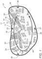
- Fig. 1 is a schematic, pictorial illustration of a system 10 for transporting objects without stopping, in accordance with an embodiment of the present invention.
- system 10 comprises a vehicle 11 having one or more cars.
- vehicle 11 comprises a train having cars 12, 14 and 16 coupled to one another and arranged in a column along a track, referred to herein as a route 33.
- vehicle 11 is configured to move, in direction 44 along route 33 having one or more stations (e.g., stations 22, 24, 29 and 30), without stopping at any of the aforementioned stations. Moreover, vehicle 11 continuously moves along route 33, typically at a predefined speed, without changing its velocity when passing by a station or when moving between stations. The speed of vehicle 11 may be constant along route 33, or may change to a desired speed in accordance with the administrative requirements of system 10.
- stations e.g., stations 22, 24, 29 and 30
- vehicle 11 continuously moves along route 33, typically at a predefined speed, without changing its velocity when passing by a station or when moving between stations.
- the speed of vehicle 11 may be constant along route 33, or may change to a desired speed in accordance with the administrative requirements of system 10.
- route 33 appears to be circular.
- route 33 may have any other suitable shape and/or configuration, such as but not limited to a linear shape (e.g., north to south), a curved shape, and/or two routes crossing one another.
- system 10 comprises one or more cars, such as cars 18, 26, 27 and 28, each of which is configured to load an object (e.g., a passenger) from a station and to move for integrating with vehicle 11.
- object e.g., a passenger
- car 18 loads passengers from station 22 and, when vehicle 11 is located at a predefined distance from station 22, car 18 starts moving along route 33 in direction 44.
- car 18 accelerates after departing from station 22 and system 10 is configured to match the speed of vehicle 11 and car 18 when making a physical contact therebetween.
- car 18 departs from station 22 before vehicle 11 passes by station 22, e.g., when vehicle 11 is located at the aforementioned predefined distance from station 22. Subsequently, car 18 accelerates, for a predefined time interval, so as to obtain approximately the speed of vehicle 11. During the predefined time interval, vehicle 11 that moves at a speed higher than that of car 18, reduces the distance therebetween. At the end of the predefined time interval, vehicle 11 makes physical contact with car 18 when the speeds of car 18 and vehicle 11 are approximately matched. Subsequently, vehicle 11 and car 18 are making a dynamic coupling therebetween so that car 18 is integrated into vehicle 11 and constitutes the front car thereof.
- the terms “about” or “approximately” for any numerical values or ranges indicate a suitable dimensional tolerance that allows the part or collection of components, or a physical parameters such as speed and time, to function for its intended purpose as described herein. More specifically, “about” or “approximately” may refer to the range of values ⁇ 20% of the recited value, e.g. "about 90%” may refer to the range of values from 71% to 99%.
- At least one of (and typically all of) the cars of system 10 is configured to detach from vehicle 11 (when vehicle 11 moves) and to decelerate for a given time interval from a respective station, so as to obtain a full stop at the respective station for unloading another object (e.g., another passenger).
- another object e.g., another passenger
- car 20 detaches from vehicle 11 and decelerates so as to stop at station 22 and to unload passengers at station 22 when vehicle 11 continues moving at a desired speed and integrates with car 18 as described above.
- car 20 which is the unloading car, is positioned at the rear of vehicle 11. Moreover, after integrating with vehicle 11, car 18 constitutes the front car of vehicle 11 as described above.
- only one car loads passengers from station 22, and only one car (e.g., car 20) unloads passengers at station 22.
- at least one of the loading and unloading cars may comprise any suitable number of cars.
- the unloading car e.g., car 20
- the loading car e.g., car 18
- the loading car may comprise multiple cars.
- car 26 is loading passengers at station 24, and starts moving along route 33 in direction 44 when vehicle 11 is positioned (while moving) at a predefined distance from station 24. Note that after integrating with vehicle 11, car 26 is the front car of vehicle 11 and car 18 will become the second car of vehicle 11.
- the position of one or more cars of vehicle 11 within vehicle 11, is changing along route 33.
- car 12 is at the front position and car 20 is at the rear position, and when approaching station 22, car 20 detaches from vehicle 11 and car 16 turns into the rear car of vehicle 11.
- car 18 is at the front position and car 16 is at the rear position, and when approaching station 24, car 16 may detach from vehicle 11 and car 14 may turn into the rear car of vehicle 11.
- vehicle 11 may pass by a given station without detaching one or more cars, and/or without integrating with a car loading passengers from the given station.
- car 16 may not detach from vehicle 11 between stations 22 and 24, and may remain the rear car having a different destination, e.g., station 29.
- vehicle 11 may integrate with car 26 between stations 24 and 29 and may have five cars (e.g., cars 26, 18, 12, 14 and 16) before detaching from car 16 when approaching station 29.
- a passenger typically boards an origin car that, after the integration, is located at the front of vehicle 11. During the ride the passenger moves within vehicle 11 in a direction 77 (opposite to direction 44), toward a destination car that is located at the rear of vehicle 11.
- the destination station of the passenger is station 29, he or she may walk from car 12 to car 14, which is designated to stop at station 29 and de-board from car 14. Note that moving passengers, within vehicle 11 in direction 77, prevents crowding and passengers congestion, and therefore, improves the mobility and flow of the passengers within vehicle 11.
- each car is a direct car to its destination station.
- direct car refers to the fact that once boarding an origin car at the origin station, a given passenger moves along vehicle 11 to its destination car and typically stops only at its destination station. In other words, the given passenger does not waste time due to a stop at any station located between the origin and destination stations, because vehicle 11 constantly moves. Therefore, from the passenger perspective, after boarding, the destination car stop only at the destination station. Moreover, a passenger sits at his or her destination car until the car is detached from vehicle 11 and stops at the destination station, while typically vehicle 11 has not changed its original (e.g., cruising) speed since departure from the origin station.
- system 10 is configured to route the cars and vehicles to transport the passenger to its destination station using various techniques described below. Moreover, due to the direct car and non-stop vehicles, the transportation is faster and the passenger spends less time commuting.
- the passengers may await at one of the cars of vehicle 11, for a notice that their destination car is integrated with vehicle 11 and is available for them.
- a passenger may (a) remain in the origin car that has a destination station that matches the passenger's destination station, or (b) move to the destination car that has not yet been integrated with vehicle 11. Note that in scenario (a), the passenger will not move in direction 77, and simply de-board the same car at the destination station.
- system 10 comprises at least the following elements: vehicles having one or more cars, cars not connected to vehicles, and the aforementioned stations located along route 33.
- system 10 has signs for assisting the passengers in reaching their destination in the most effective manner.
- digital (electronic) signs are positioned (a) in every station, (b) in every car, and (c) the passengers may have a handheld device, such as a smartphone or a head-mounted display (HMD), which is connected to a control sub-system of system 10 and displays information regarding the schedule and destination of each car of system 10.
- HMD head-mounted display
- each station has signs indicative of the departure and arrival times of cars at the station, and optionally on departures and arrivals of cars at other stations of system 10.
- the signs of station 22 may display the arrival time of car 20 and the departure of car 20 that will be integrated with the next vehicle (not shown) following vehicle 11.
- the signs of station 24 may display (a) the departure time of car 26, and in case car 16 is scheduled to detach from vehicle 11 and to stop at station 24, the signs will display (b) the arrival time of car 16.
- the signs of each station may also display information regarding other stations along route 33 and the destination of each car currently integrated in vehicle 11.
- each car has a sign that marks the destination station thereof.
- the sign may also comprise a mapping of all the cars of system 10, which are lit according to coupling and destination station.
- Such signs provide the passengers with information on the destinations of all cars currently integrated in vehicle 11. Thus, each passenger knows his or her destination car in order to reach the respective destination station.
- the signage may display the status and destination of each car of system 10, or of some of the cars of system 10.
- the term "status" may refer to at least one of (a) whether the car moves or stops, (b) whether the car (i) loads passengers, or (ii) unloads passengers, or (iii) in idle or mode (e.g., for technical maintenance, or cleaning).
- a moving car may be highlighted, and displays its corresponding destination.
- a car that is positioned at a given station, and therefore is not moving may have a corresponding indication of its status as described above, and a sign indicative of its destination that may be displayed at all stations, cars and personal displays.
- the signage may provide users with an indication of whether or not each car is dynamically coupled to a respective vehicle. In the example of Fig. 1 , the signage will indicate that cars 12, 14 and 16 are dynamically coupled to one another, whereas cars 18 and 20 are moving but are not coupled to any car of vehicle 11.
- the signage may be carried out using color-coding, letters, lit and unlit, characters, or any other suitable marking indicative of the status of the respective car.
- each car may have the destination thereof shown on the outer surface of the car so that passengers at the respective stations will be able to see the destination of the respective car.
- passengers having a personal displaying device such as but not limited to the aforementioned smartphone or HMD, may have all the information described above displayed on the personal device.
- the personal device may provide the user with the destination of the car he or she is currently located in, and may further provide the user with the position of its destination car and the estimated arrival time of the destination car at the destination station.
- system 10 comprises the aforementioned control sub-system.
- the control sub-system may be centralized, referred to herein as a central control unit (CCU).
- the control sub-system may be distributed, referred to herein as a distributed control unit (DCU).
- a DCU may be positioned at the large stations of system 10 that are distributed along route 33 and/or as local-control units (LCUs) coupled to at least some of the aforementioned cars of system 10, as will be described in detail in Fig. 2 below.
- LCUs local-control units
- the CCU may comprise various types of sensors, communication devices, controllers and processors (described in detail below), which are configured to accurately assess the position, speed and acceleration of each car in real-time.
- a processor of the CCU is configured to estimate and/or specify various parameters related to components (e.g., each car and vehicle) of system 10.
- the processor is configured to control (a) speed, (b) acceleration and deceleration, (c) a distance between adjacent car or vehicle, (d) a distance to and/or from a nearest station, (e) a distance to a closest obstacle or hazard, (f) status of each car, such as but not limited to detaching from a vehicle, integrating with a vehicle, awaiting at a station, (g) status of the vehicle, e.g., number of cars and motors integrated in the vehicle, and (h) braking capabilities.
- braking capability refers to at least one of (i) reducing the power applied to a motor (e.g., electrical, diesel) driving the respective car, and (ii) applying a mechanical braking assembly (e.g., friction-based) for stopping the respective car.
- a motor e.g., electrical, diesel
- a mechanical braking assembly e.g., friction-based
- Both braking capabilities are affected by various parameters, such as but not limited to (a) total weight of the car, (b) materials of the mechanical braking assembly, (c) number of mechanical braking actuators used (e.g., not bypassed) in the braking assembly, (d) latency period for activating a braking actuator (e.g., building a pressure in braking pistons), and (e) temperature of the braking environment and of elements of the mechanical braking assembly.
- the CCU is configured for signaling and controlling the components speed, acceleration and for commanding coupling and/or de-coupling between at least two cars and between a car and a vehicle.
- the CCU is further configured to command cars and/or vehicles to abort coupling and/or decoupling processes when required.
- one or more of the control sub-systems e.g., CCU, and/or in stations, and/or in cars
- the control sub-system is configured to specify the configuration of at least one of the vehicle (e.g., vehicle 11) and one or more of the aforementioned cars of system 10.
- control sub-system comprises a general-purpose computer having at least a processor and/or a controller, which is programmed in software to carry out the functions described herein.
- the software may be downloaded to the computer in electronic form, over a network, for example, or it may, alternatively or additionally, be provided and/or stored on non-transitory tangible media, such as magnetic, optical, or electronic memory.
- vehicle 11 may have less cars than number of stations.
- one or more given cars of vehicle 11 may have respective destination stations, but also intermediate destination stations. In such embodiments, the passengers will wait in the given car they boarded until the car of their destination is picked up later, and then pass to their destination car at the front of vehicle 11.
- system 10 is configured to manage connection of passengers between different routes having at least one common station. For example, a passenger departing from Pittsburgh Pennsylvania with a destination station at Richmond Virginia, will wait at a given car dropped-off at the Baltimore station, and the given car will be integrated with the vehicle coming from New York using the same techniques described above for car 18 and vehicle 11. After the integration, the passenger may walk to the destination car intended to stop at Richmond as its destination station.
- an alternative embodiment of system 10 is possible in cases where destination car is unavailable due to a short vehicle 11.
- the passengers remain in an "intermediate car" but may not de-board from the intermediate car even though the intermediate car is detached from vehicle 11 and stops at a station, because the intermediate car will integrate with a subsequent vehicle (other than vehicle 11). After the integration with the subsequent vehicle, the passengers will move towards the back of the subsequent vehicle, to the destination car of their destination.
- the cars constituting vehicle 11 may be concatenated or split to allow better utilization of the shared vehicles. Because the passengers typically sit in their destination car before the splitting, the passengers do not move while vehicle 11 is being split, thus avoiding safety events. In such embodiments, when accessing a station (e.g., by foot), each passenger may relate to the car awaiting at the platform as his or her next car, assuming that all cars and vehicles that are sharing the same line are concatenated and/or split as needed. These embodiments are applicable for all passengers because each vehicle that passes through a station can arrive to all possible stations by concatenating and splitting.
- a vehicle having a first set of cars of system 10 is configured to merge with another vehicle having a second set of cars, and/or to split into multiple sub-vehicles.
- the rear-most-sub-vehicle also referred to herein as the second set of cars
- reduces its speed to a predefined speed so as to have a safety distance and to allow the one or more front sub-vehicles (also referred to herein as the first set of cars) to leave the splitting point.
- the one or more front sub-vehicles and the rear-most-sub-vehicle are routed, each, by the CCU of system 10 to their respective routes, and the rear-most-sub-vehicle restores its original or planned speed.
- safety is obtained using a transition mechanism, which allows both cars (the rear and the front) to know, with sufficiently-high accuracy and confidence level, the actual distance and speed difference during the entire coupling process between adjacent cars and thereafter.
- the rear car in case of a communication-loss event during the dynamic coupling, stops immediately and the front car (or vehicle) also stops but after a time interval (depending on the position and speed of the cars), and at a lower deceleration rate, so as to maintain a safety distance therebetween.
- the front car in case of a communication-loss event during dynamic coupling of front and rear cars, the front car will always move faster than the rear car so as to prevent a collision and to obtain a safety distance therebetween.
- each car of system 10 is configured to use the same communication and synchronization techniques in case of a need for an emergency stop at a given car.
- the vehicle may start decelerating and/or stopping, and send a signal to the car in front of it that it can start decelerating and/or stopping at a slightly lower rate than the vehicle (e.g., vehicle 11), in order to maintain the safe distance between the vehicle and the front car.
- the same emergency stop technique may be applied to any car within vehicle 11 or to any other vehicle.
- a vehicle comprising three cars, referred to herein as a front car, a middle car, and a rear car, which may have an uncontrolled fire event in the middle car.
- the front car decouples from the burning middle car and moves at the fastest speed from among the three cars.
- the burning middle car moves at a speed slower than that of the front car, and the rear car, which is also decoupled from the burning middle car, moves at the slowest speed from among the three cars.
- the CCU may control a diversion apparatus in route 33 to divert the burning car to a suitable different route and to stop the burning car for extinguishing the fire and other types of emergency activities at a designated safety area.
- the distance between two or more adjacent stations may be short due to high density of passengers or goods distributed within a short section of the route.
- a metropolis for passengers and parcels
- a seaport or airport for large cargo and/or freight
- a passenger boarding the front car may have to rush to his or her destination car, and in some cases, the passenger may not be able to reach the destination car on time.
- control sub-system of system 10 is configured to specify the number of cars in vehicle 11, e.g., based on the distance between at least two adjacent stations of route 33.
- system 10 may comprise a combination of (a) long vehicles for long distances between adjacent stations as described above, and (b) shorter vehicles (e.g., having less cars) for serving sections of a route having short distances between adjacent stations.
- a shorter vehicle may comprise two or three cars, so that a passenger have to move only one or two cars during the ride between two adjacent stations, and therefore, may not have a problem to get to his or her destination car on time. Note that both the long and short vehicles are not stopping at stations of the metropolis, but are detaching from and coupling to cars before and after the stations, respectively.
- system 10 may comprise a combination of vehicles that are not stopping, referred to herein as non-stop vehicles such as vehicle 11, and "traditional vehicles” that stop at predefined stations for loading and unloading objects (e.g., passengers or parcels).
- non-stop vehicles such as vehicle 11, and "traditional vehicles” that stop at predefined stations for loading and unloading objects (e.g., passengers or parcels).
- system 10 may comprise three non-stop vehicles, such as vehicle 11, and one traditional vehicle.
- the first and second non-stop vehicles e.g., arriving from stations out of the metropolis
- the traditional vehicle may load passengers at the given stations and transport them to their destination within the metropolis.
- the third non-stop vehicle may couple to cars loading passengers from the given stations and/or other stations, for transporting these passengers to stations located at distances long-enough that provide passengers with enough time to reach their destination car on time.
- at least one of the three non-stop cars may both load and unload passengers at predefined stations. For example, a first non-stop vehicle may only detach cars, a second non-stop vehicle may detach from and integrate with cars, and a third non-stop vehicle may only integrate with cars.
- system 10 may comprise only non-stop vehicles that may move fast between metropolises and slower within the metropolises so as to provide the passengers with enough time to safely reach their destination cars before the detachment. Additionally or alternatively, system 10 may dynamically adjust the speed of the non-stop vehicles based on information received from the ticketing system. Note that the speed adjustment is limited so as to maintain the original schedule of the loading and unloading at the stations of system 10.
- system 10 may comprise two cars, denoted cars “A” and "B,” and a single station.
- car “A” loads passengers from the station and integrates with car B, and when approaching the station, car “B” detaches from car “A” and unloads passengers at the station.
- This minimal configuration may be used, for example, for improving the utilization of an attraction in an amusement park, or for any other suitable application for transporting passengers and/or goods.
- control sub-system of system 10 is configured to receive information from the ticketing system, and based on the information, to specify and/or adjust the number of cars at the first station, in response to the unusual number of passengers.
- a first non-stop vehicle may detach, in the first station before the large amount of passengers are boarding, three cars instead of one.
- a subsequent second non-stop vehicle may integrate with the three cars having the large amount of passengers returning from the event, and detach the three cars at the second station so as to unload at least some of the passengers returning from the event, at their destination station.
- the second non-stop vehicle may detach two of the cars at the second station and the remaining additional cars at the third station.
- These embodiments are also applicable for rush hours in crowded areas, such as a metropolis (for passengers and/or parcels) and a port (for cargo and/or freight).
- control sub-system based on the information received from the ticketing system indicative of unusually large number of objects at the first station, the control sub-system is configured to specify (e.g., limit) the number of tickets for the second non-stop vehicle and the remaining passengers may be permitted to board a subsequent third non-stop vehicle.
- vehicle 11 and the cars of system 10 may comprise any other suitable type of transportation equipment, such as but not limited to a bus, an intercity train, a light train, a suburban rail, an underground train, a boat, an automobile, a truck, and a cargo and/or freight carrier (e.g., a train, a truck or a ship).
- vehicle 11 may comprise an aircraft (e.g., a drone) configured to carry passengers and/or parcels along a predefined route, and the cars may comprise smaller drones configured to load and unload the passengers and/or parcels between the aircraft and the stations.
- vehicle 11 is configured to stop for coupling to and/or for detaching cars. These embodiments may be useful in case the dynamic coupling and detaching is too complicated and/or risky. This operational mode reduces some of the benefits for passengers, and may result in a long delay to passengers that plan to de-board at intermediate stations and longer overall cycle time of route 33.
- vehicle 11 may slow down before stations so that the dynamic coupling and decoupling (or detaching) may be carried out at lower speed. For example, if the cruising speed of vehicle 11 between stations is about 400 km per hour (KPH), the speed may decline to about 100 KPH before the dynamic coupling and/or decoupling.
- this intermediate concept may be applied using any other suitable operational mode subject to the type of transportation as described above. For example, the speed acceleration and deceleration may differ between an intercity train and a suburban rail, and between transportation of passengers and cargo and/or freight.
- system 10 is shown by way of example, in order to illustrate certain problems that are addressed by embodiments of the present invention and to demonstrate the application of these embodiments in enhancing the performance of such a transportation system.
- Embodiments of the present invention are by no means limited to this specific sort of example system, and the principles described herein may similarly be applied to other sorts of transportation systems.
- Fig. 2 is a diagram that schematically illustrates a process for connecting two moving cars 12 and 18 of system 10, in accordance with an embodiment of the present invention. Note that the following embodiments described below for cars 12 and 18 are applicable for all the cars of system 10, and that at least one of cars 12 and 18 may be coupled to additional cars, as described in Fig. 1 above.
- cars 12 and 18 comprise, each, a local-control unit (LCU) 54, which is part of the distributed control unit (DCU) described in Fig. 1 above.
- LCU 54 comprises one or more sensors 56, which are configured to sense several physical parameters of the respective car.
- sensors 56 of car 12 may sense speed, acceleration and deceleration of car 12, a distance between cars 12 and 18 as shown in the steps of Fig. 2 , and a distance to a hazard.
- sensors 56 are shown as a box in LCU 54, but each of the aforementioned sensors 56 may be fitted at any suitable position of car 12 (and one or more other cars of system 10).
- sensors 56 for measuring the distance between car 12 and an adjacent car may be fitted at positions 58 and 59 of car 12.
- the sensor at position 58 is configured to measure the distance between cars 12 and 18.
- LCU 54 comprises one or more communication devices 57, which are configured to exchange signals indicative of the aforementioned measured parameters, instructions received from any processing unit of system 10, and any other suitable information.
- LCU 54 comprises a processor 55, which is configured to receive, via electrical conductors 51 (e.g., cables, wires, leads, traces) or wirelessly, signals indicative of the parameters sensed by sensors 56 and information received from communication devices 57.
- processor 55 of car 12 is configured to control (a) motion parameters of car 12, (b) coupling and decoupling procedures between car 12 and adjacent cars, as will be described in detail herein, and any other operations of car 12 and optionally of other cars of system 10.
- motion parameters refers to speed, acceleration, deceleration, braking, changing course, and any other suitable parameters related to the motion of the respective cars of system 10 (e.g., cars 12 and 18).
- LCU 54 may comprise electrical conductors 52, configured to exchange signals directly between sensors 56 and communication devices 57. This configuration may be useful, for example, for controlling both cars 12 and 18 using a single processor 55 that serves as a master processor.
- processor 55 of car 18 may serve as a master processor that may receive the parameters sensed by sensors 56 of car 12, and may control, for example, the motion parameters of both cars 18 and 12.
- processor 55 of the front car is typically defined as the master processor
- processor 55 of the rear car is defined as the slave processor.
- cars 12 and 18 are moving in direction 44, so that processor 55 of car 18 is defined as the master processor.
- processor 55 of car 18 controls the distance between cars 12 and 18, so that in case of emergency during a coupling process between cars 12 and 18, processor 55 of car 18 controls car 12 to reduce speed (or even stop) before changing the speed of car 18, so as to prevent a collision between cars 18 and 12.
- both processors 55 of cars 12 and 18 may be slaves to a third party master processor, as described in detail herein.
- processors 55 of cars 12 and 18 may be local masters of their respective car.
- processor 55 of the rear car e.g., car 12
- processor 55 of the rear car may serve as the master processor of both cars 12 and 18.
- car refers to the car that is not at the front (in direction 44) from among the cars being coupled or decoupled.
- car 12 serves as the rear/trailing car.
- front car and leading car are used interchangeably and refer to car 18 in the example of Fig. 2 .
- the aforementioned signals may be transmitted from and received by communication devices 57, via electrical conductors 51 and 52, and via any suitable type of wireless signals 53.
- communication devices 57 of cars 12 and 18 are configured to exchange at least some of the signals described above, so as to control the motion parameters of cars 12 and 18.
- both processors 55 of cars 12 and 18 may be slaves to a third party master processor, located for example at the aforementioned controlled sub-system (e.g., CCU) of system 10 or at any other location.
- both communication devices 57 of cars 12 and 18 may send data to the third party master processor, and processors 55 of cars 12 and 18 may receive instructions from the third party master processor.
- one of processors 55 e.g., the processor of car 18, which is the front car
- car 12 comprises a coupling assembly (CA) 100, which is coupled to car 12 at a location 90.
- car 18 comprises a (CA) 101, which is coupled to car 18 at a location 91, and may have a configuration substantially identical to that of CA 100 described herein.
- cars 12 and 18 are moving along route 33 in direction 44, so that location 90 is positioned at the front side of car 12, and location 91 is positioned at the rear side of car 18.
- at least one car of system 10 may have one or more CAs positioned at other locations.
- CA 100 may be positioned at another location of car 12, and additional CAs may be mounted on car 12 at any suitable locations other than 90 and 92.
- all cars of system 10 may have CAs coupled at both front and rear locations thereof.
- car 12 may have an additional CA (not shown) coupled at location 92, so that car 12 may be coupled with an additional car, such as car 14 as shown in Fig. 1 above.
- CA 100 comprises a telescopic extender (TE) 88, so that while at least car 12 is in motion, TE 88 is configured to extend away from car 12 for connecting with car 18.
- CA 100 comprises a connector (CN) 99, which is coupled at the distal end of TE 88, but in other embodiments, CN 99 may be coupled at any other suitable position of TE 88.
- CA 101 comprises a TE 87 having the same features of TE 88.
- TE 87 is configured to extend away from car 18 (e.g., toward CA 100 in car 12).
- CA 101 comprises a CN 98, which is typically (but not necessarily) positioned at the distal end of TE 87 and having the same features of CN 99.
- CN 99 is configured to connect with a mating connector, such as CN 98, for connecting between cars 12 and 18.
- CAs 100 and 101 and controlled by processors 55 of cars 12 and 18, respectively.
- CAs 100 and 101 may be controlled by a local controller, or by a master processor (e.g., processor 55 of car 18 or a remote master, such as the third party master) as described above.
- TEs 87 and 88 are configured, each, to be extended up to a predefined distance, e.g., between zero and five meters.
- the amount of extension depends on the safety requirements of the particular type of vehicle and cars. For example, the extension of each TE in a train may be about two, or three or four meters (or any other suitable size), whereas the extension in an automobile may be about one meter or less (or any other suitable size).
- the specified predefined distance may be determined, inter alia, based on the momentum (e.g., weight and/or speed) of the car, communication time delay, and the braking ability (e.g., deceleration rate, and/or distance the car is passing from receiving a stop command, time and distance to full stop).
- car 18 loads passengers from station 22 and, when car 12 of vehicle 11 is located at a predefined distance from station 22, car 18 starts moving along route 33 in direction 44.
- car 18 accelerates for a predefined time interval, so as to obtain approximately the speed of car 12.
- cars 12 and 18 are both moving and are separated from one another by a distance 112.
- TEs 88 and 87 are both in a collapsed and remain within cars 12 and 18, respectively.
- a first extension step 104 when car 18 still accelerates during the predefined time interval, car 12 moves at a speed higher than that of car 18, and thereby, is separated from car 18 at a distance 114, smaller than distance 112 of step 102 above.
- a second extension step 106 both cars 12 and 16 are moving, but car 12 still moves at a speed higher than that of car 18, and therefore, is separated from car 18 at a distance 116, smaller than distance 114 of step 104 above.
- TEs 88 and 87 may continue to extend toward the other TE for making physical contact between CNs 99 and 98.
- both TEs 88 and 87 may extend, or only one TE (e.g., TE 88) may extend while TE 87 may remain collapsed. Note that when one TE remains collapsed, the distance for coupling may be shortened (e.g., by half).
- CNs 99 and 98 are connecting with one another at the end of step 106, embodiments related to the connecting process between CNs 99 and 98 is described in detail in Figs. 3A-3C below.
- At least one of TEs 87 and 88 may start extending only when both cars 12 and 18 are moving at the same speed, and at least one of cars 12 and 18 may accelerate or decelerate to accommodate for the required approximation between cars 12 and 18.
- TEs 88 and 87 may be used as dampers, configured to compensate for any variation in the relative speed between cars 12 and 18.
- TEs 88 and 87 may be used as hard dampers, for example, by pushing against car 12, which is over-approaching toward car 18, and thereby, maintain distance 116 at step 106.
- TEs 88 and 87 may be used as soft dampers.
- processor 55 is configured to control at least one of TEs 88 and 87 to slightly collapse, while adjusting the relative speed between cars 12 and 18, and to extend after adjusting the relative speed and maintaining the specified distance between cars 12 and 18.
- TE 88 is configured to collapse toward car 12: (a) when cars 12 and 18 are getting closer to one another, or (b) when car 12 and 18 are disconnecting from one another. In other embodiments, TE 88 may remain fully or partially extended when car 12 and 18 are disconnecting from one another.
- electrical modules (not shown) of CAs 101 and 100 are coupled to one another, so that electricity, and various types of signals may be exchanged between cars 12 and 18.
- communication devices 57 of cars 12 and 18 may exchange at least some signals using a wired communication channel, in addition to or instead of using wireless signals 53 described above.
- communication devices 57 are configured to receive a signal indicating the availability of the wired communication channel, and based on the signal, to select between the wired and wireless channels for transmitting the signals.
- Step 110 terminates the process for connecting two moving cars 12 and 18, and after concluding step 110, car 18 is integrated with vehicle 11 as described in Fig. 1 above.
- a reversed order of the process described in fig. 2 may be used, mutatis mutandis, for disconnecting between two cars of vehicle 11.
- the force e.g., mutual pressure
- the rare car e.g., car 12
- the front car may slightly decelerate
- TEs 87 and 88 may be extended while CNs 98 and 99 are still connected with one another, e.g., as shown for example in step 108. Subsequently, when distance 112 is sufficiently large, e.g., as shown in step 106, CNs 98 and 99 are disconnecting from one another and TEs 87 and 88 are collapsing toward cars 18 and 12, respectively.
- step 106 the damping embodiments described in step 106 above, are also applicable for steps 108 and 110, as well as for the corresponding steps of the process for disconnecting between any cars (e.g., cars 12 and 18) of vehicle 11. Additional embodiments related to the extension and damping are described below.
- TEs 87 and 88 may remain collapsed when cars 12 and 18 are disconnecting from one another.
- CNs 98 and 99 are disconnecting from one another at about the same time (or shortly before) cars 18 and 12 are decoupling from one another.
- At least one of cars 12 and 18 may have a non-extending element having connectors, such as but not limited to CNs 98 and 99.
- These non-extending elements may be used for connecting between cars 12 and 18, and may also serve as dampers for damping any impact occurring by the coupling between cars 12 and 18.
- Coupling cars using such non-extending elements typically require fast communication and good coordination for performing a virtual coupling between cars 12 and 18.
- the term "virtual coupling" is described in detail below.
- extenders such as but not limited to TEs 87 and 88, or any other type of non-telescopic extenders described below, may be used for damping the impact occurred when coupling between cars 12 and 18.
- At least one of TEs 87 and 88 may not collapse at step 108, for example, when connecting between cars 12 and 18 without transferring people and/or other objects between the cars.
- cars 12 and 18 may be coupled via TEs 87 and 88 and connected between CNs 98 and 99, but the bodies of cars 12 and 18 remain separated from one another at a predefined distance (e.g., distance 116 or 118).
- the processor 55 comprises a general-purpose processor, which is programmed in software to carry out the functions described herein.
- the software may be downloaded to the computer in electronic form, over a network, for example, or it may, alternatively or additionally, be provided and/or stored on non-transitory tangible media, such as magnetic, optical, or electronic memory.
- At least one of cars 12 and 18 may have, in addition to TEs 88 and 87, one or more extenders that are not telescopic.
- an extender shaped as a squeezebox of an accordion may be compressed instead of the collapsing of the TE, and expanded, instead of the extending of the TE.
- Other examples of a non-telescopic extenders may be designed as a folding fence used in gardens and gates or any other suitable type of a controllable extending and collapsing apparatus.
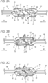
- Figs. 3A, 3B and 3C are schematic, sectional views of three respective positions of CNs 98 and 99 used for dynamically connecting moving cars 12 and 18 of system 10, in accordance with an embodiment of the present invention. As described in Fig. 2 above CNs 98 and 99 are coupled, respectively, to TEs 87 and 88.
- CNs 98 and 99 are both moving in direction 44, however, due to the different speeds of cars 18 and 12, CNs 98 and 99 are actually moving toward one another in opposite directions 70 and 60, respectively.
- CN 99 comprises a housing 61 having a distal end shaped as a cone 64.
- CN 99 comprises a disc 66, which is configured to rotate about a hinge 65.
- disc 66 is rotated clockwise for connecting between CNs 98 and 99 as will be described in detail in Figs. 3B and 3C below.
- a section of the circumference of disc 66 is shaped as an arc 67, and a notch 63 is formed in arc 67.
- a spring 68 is coupled between disc 66 and housing 61, and a shaft 69 is coupled to a hinge 62.
- CN 98 comprises a housing 71 having a distal end shaped as a cone 74.
- CN 98 comprises a disc 76, which is configured to rotate about a hinge 75. In a like manner to disc 66 described above, disc 76 is rotated clockwise for connecting between CNs 98 and 99.
- a section of the circumference of disc 76 is shaped as an arc 80, and a notch 73 is formed in arc 80.
- a spring 78 is coupled between disc 76 and housing 71, and a shaft 79 is coupled to a hinge 72.
- Shafts 69 and 79 are typically made from a rigid metal or any other suitable material. Note that shafts 69 and 79 pass, respectively, through openings of cones 64 and 74 of respective housings 61 and 71, such that the distal end of shaft 69 makes contact with arc 80 of disc 76 , and the distal end of shaft 79 makes contact with arc 67 of disc 66 .
- cones 64 and 74 are shaped such that when CNs 98 and 99 are moving toward one another (e.g., in directions 70 and 60, respectively), cone 64 fits over cone 74.
- TE 88 moves CN 99 in direction 60
- disc 66 rotates clockwise and brings notch 63 in close proximity to the distal end (i.e., the end not connected to hinge 72) of shaft 79.
- spring 68 of CN 99 is being stretched.
- TE 87 moves CN 98 in direction 70
- disc 76 rotates clockwise and brings notch 73 in close proximity to the distal end of shaft 79, and spring 78 is being stretched.
- shafts 69 and 79 When discs 66 and 76 are sufficiently-rotated clockwise, the distal ends of shafts 69 and 79 are inserted into notches 73 and 63, respectively.
- the distal ends of shafts 69 and 79 may have a pin, or any other suitable apparatus, for insertion into notches 73 and 63, respectively.
- FIG. 3C showing a mechanism for locking CNs 98 and 99 to one another.
- the distal ends of shafts 69 and 79 are inserted into notches 63 and 73, respectively, and are stopping against respective discs 76 and 66. Subsequently, shafts 69 and 79 are pressed back into CNs 99 and 98, respectively, causing discs 76 and 66 to rotate until notches 73 and 63 align with shafts 69 and 79.
- CNs 98 and 99 The structure and functionality of CNs 98 and 99 is based on Scharfenberg couplers, provided, for example, by Voith Turbo Scharfenberg GmbH (Salzgitter, Germany).
- CAs 100 and 101 may have any other suitable type of couplers or connectors, instead of or in addition to CNs 98 and 99.
- uncoupling between CNs 98 and 99 is executed by rotating at least one of the discs against the force of the respective spring. For example, rotating disc 66 clockwise against the force of spring 68. In response the clockwise rotation, the distal end of the respective shaft (e.g., shaft 79) is released from the respective notch (e.g., notch 63), and the same applies for shaft 69 and notch 73. As a result, CNs 98 and 99 are uncoupled. Note that the coupling and uncoupling of CNs 98 and 99, as described above, may be carried out manually, or using electrical and/or pneumatic mechanisms controlled, for example, by processor 55 and/or by an operator of the respective cars and/or of system 10. Additional embodiment and variations are described in detail, after Fig. 4 below.
- system 10 and the cars thereof may comprise any other type of transportation vehicle, such as but not limited to a bus, an intercity train, a light train, a suburban rail, an underground train, a boat, an automobile, a truck and an aircraft.
- the cars (e.g., cars 12 and 18) of system 10 may transport any suitable types of objects, such as but not limited to, passengers, parcels, cargo and/or freight, or any suitable combination thereof.
- Fig. 4 is a flow chart that schematically illustrates a method for dynamically connecting two or more moving cars of system 10, in accordance with an embodiment of the present invention.
- the method begins at a first distance setting step 200, with setting a first distance between first and second moving cars. For example, setting distance 116 separating between moving cars 12 and 18 shown in Fig. 2 above.
- a first distance setting step 200 with setting a first distance between first and second moving cars. For example, setting distance 116 separating between moving cars 12 and 18 shown in Fig. 2 above.
- TE 88 of car 12 is extended toward car 18, and TE 87 of car 18 is extended toward car 12.
- CN 99 which is coupled to TE 88, is connected with a mating connector, e.g., CN 98, of car 18, as shown for example in step 106 of Fig. 2 above.
- a second distance (e.g., distance 118 of Fig. 2 above), which is smaller than distance 116, is set for separating between moving cars 12 and 18, and at the same time, TEs 88 and 87 collapse toward cars 12 and 18, respectively, so that a combination of controlling the speed of cars 12 and 18 to obtain distance 118 and moving at least one of TEs 88 and 87 enables the latching and/or locking described in Fig. 2 above.
- cars 12 and 18 are coupled to one another while moving and collapsing TEs 88 and 87 toward cars 12 and 18, respectively.
- car 18 is integrated with vehicle 11 as described in Figs. 1 and 2 above.
- Dynamic coupling assumes that the speed of two consecutive components (e.g., cars 12 and 18) is known with a relatively high accuracy and known delay. Thus, conventional safety margins (which assume static obstacles) are relatively conservative and therefore, expensive in terms of volume transportation. As such, relative speed (rather than absolute speed) is considered as a key parameter for deriving the safety requirements of system 10. Measuring relative speed allows two consecutive components (e.g., cars 12 and 18) to get in close proximity to one another while maintaining a sufficiently-safe distance therebetween. As described in Fig. 2 above, by having LCUs 54, cars are virtually mutually connected and informed of various parameters of one another, such as motion parameters (e.g., speed and acceleration).
- motion parameters e.g., speed and acceleration
- the coupling mechanism of system 10 may comprise: CNs 98 and 99 or any other suitable type of automatic coupler, TEs 87 and 88 for extension and damping as described in Fig. 2 above, a communication channel (e.g., between communication devices 57 of cars 12 and 18), sensors 56 for sensing the aforementioned motion parameters and distance between adjacent cars 12 and 18, processors 55 for controlling the motion parameters, distance between adjacent cars 12 and 18, and the operation of CAs 100 and 101 for coupling and decoupling between adjacent cars.
- a communication channel e.g., between communication devices 57 of cars 12 and 18
- sensors 56 for sensing the aforementioned motion parameters and distance between adjacent cars 12 and 18
- processors 55 for controlling the motion parameters, distance between adjacent cars 12 and 18, and the operation of CAs 100 and 101 for coupling and decoupling between adjacent cars.
- the coupling mechanism may comprise a hazard and safety control mechanism, for example, using software features for controlling the aforementioned coupling and decoupling in response to input signals, such as detection of obstacles, or receiving negative clearance from the railway signaling system or train control system or other types of hazards along route 33.
- the communication channel is capable of transferring distance and speed measurements in real-time, as well as potential hazard alerts, while controlling speed and acceleration of both cars.
- the speed and acceleration are adapted, so as to reduce relative speed, and thereby, allowing safe coupling.
- processor 55 activates CAs 100 and 101, so as to lock the automatic couplers (e.g., CNs 98 and 99) to one another and latch or be locked using any suitable technique.
- the dynamic coupling (as well as decoupling) between adjacent cars 12 and 18 is carried out under the supervision of the aforementioned hazard and safety control mechanism, which is implemented, for example, using processors 55, and is described in detail below.
- LCUs 54 are configured to continuously sense various parameters (as described in Figs. 1 and 2 above) and to response to any variation in the dynamics of cars 12 and 18, so the leading car (e.g., car 18) does not change speed before ascertaining that the trailer car (e.g., car 12) started braking or reducing speed at a slowing rate determined, for example, by processor 55.
- TEs 87 and 88 that serve as a coupling extension and damper mechanism, allow cars 12 and 18 that are maintained, e.g., by processors 55, in controlled distance and speed relative to one another, to couple and latch (e.g., having CNs 98 and 99 locked). Subsequently, TEs 87 and 88 are collapsed toward cars 18 and 12, respectively, and cars 12 and 18 are now coupled and moving in tandem as cars of vehicle 11.
- couplers for connecting between cars 12 and 18: (a) a manual coupler, using a mechanical, or pneumatic, or electrical connections, (b) a semi-automatic coupler, having an automatic mechanical connection, but manual only pneumatic and/or electric connections, and (c) fully automated couplers.
- the semi-automatic coupler also referred to herein as a semi-permanent coupler, is designed to ensure a permanent mechanical and pneumatic connection between the different cars of vehicle 11. The semi-permanent coupler does not have to be uncoupled unless there is a case of emergency or during maintenance of one or more of the connected cars.
- the semi-permanent coupler has a vulcanized metal-rubber articulation that allows relative movement between the cars. This coupler allows the coupled cars to resist both horizontal and vertical vibrations, as well as rotational movements.
- One or both of the two couplers between cars is provided with an energy absorption device, which is configured to absorb mechanical forces applied between the cars (e.g., between cars 12 and 18).
- an automatic coupler is configured to carry out mechanical coupling between two cars, by means of a simple approximation at a recommended speed of about 5 kilometer per hour (KPH), without any manual assistance.
- the electric and pneumatic connection of the respective cars are carried out automatically at the same time with the mechanical coupling.
- the automatic coupler allows the coupled cars to resist both horizontal and vertical vibrations, as well as a rotational movement. Uncoupling the cars is also automatic, and is carried out from the driver's desk, although in case of emergency it can be carried out manually by means of an uncoupling handle.
- the automatic coupler is provided with an energy absorption device, configured to collapse under strong impacts for protecting the frames of the involved cars.
- Such automatic couplers may be supplied by various manufacturers, such as the aforementioned Voith GmbH, and other producers described in U.S. Provisional Patent Application 62/877,853 (attorney docket number 1373-2003) filed July 24, 2019 , whose disclosure is incorporated herein by reference.
- Train virtual coupling is a technology that applies direct (or indirect) communication between adjacent cars, such as cars 12 and 18, for shortening a safety distance therebetween.
- the specified safety distance takes in account the dynamics (e.g., motion parameters of each car and distance measured between the cars), relying on the communication channel (described above) between cars 12 and 18, and in the example of Fig. 2 , automating the response of car 12 (also referred to herein as the trailing car in the present example) to hazard alert provided by car 18 (also referred to herein as the leading car in the present example), so as to prevent collision between cars 12 and 18.
- the term “derailment” refers to a car of system 10 falling out of route 33 undesirably (e.g., by accident). For example, when a train is getting off-track or when an automobile is falling off-road. Such undesired accidents are hazardous for passengers and other objects transported by the cars and vehicles of system 10 or any other transportation system. In these cases, the leading train, about to collide with the derailed train, cannot provide hazard alert in time to the virtually coupled second train, thus the latter does not have time to decelerate and will cause even higher speed collision.
- system 10 is configured to address safety issues of virtual coupling by shortening the virtual coupling time-window required for physical connection during which it can be assured no opposite train or intersection is present, removing the virtual coupling drawbacks completely.
- one or more cars (typically all cars) of system 10 comprise an automatic coupler, such as CAs 101 and 100 having respective CNs 98 and 99 as shown in Fig. 2 above.
- the CAs are typically coupled at both side of the car so as to enable connecting with cars at the front and back sides of the car.
- CA 100 is coupled at the front side (e.g., location 90) and an additional CA is coupled at the back side (e.g., location 92) of car 12.
- CAs 100 and 101 and the TEs and CNs thereof are applicable for all CAs, TEs and CNs of all cars of system 10.
- CNs 98 and 99 are configured to latch and lock automatically in response to having a predefined range of relative speeds between one another (e.g., between about 3 KPH and 5 KPH), using the connecting and locking mechanism described in Figs. 3A-3C above, or by using any other suitable mechanism.
- CNs 98 and 99 are configured to operate under longitudinal and lateral forces and vibrations, and to support a predefined range of tilting and rotation angles such as requirements specified in various railway engineering standards, e.g., I.S. EN 12663-1:2010, SS-EN 16019:2014, between cars 12 and 18, for example based on the interaction between cones 64 and 74 described in Figs. 3A-3C above.
- each CA of system 10 comprises an electronic module (not shown), such that after CNs 98 and 99 are mechanically connected and locked, the electronic modules of CAs 100 and 101, are electrically connected, and are configured to produce signals indicative of the coupling status between CNs 98 and 99.
- communication devices 57 of CAs 100 and 101 are configured to exchange at least one of the communication signals over a wired connection (not shown) coupled between the electronic modules of CAs 100 and 101.
- CAs 100 and 101 are operated using electrical power provided by cars 12 and 18, respectively, CNs 98 and 99 may be operated (e.g., latching/locking and releasing) manually, for example, in case of emergency.
- TEs 87 and 88 are configured to provide to suppress and/or contain vibration differences between cars 12 and 18 and to sustain longitudinal forces and different required angles of the coupling after connecting CAs 100 and 101 successfully.
- CAs 100 and 101 are designed for high speed trains (e.g., trains, metro, and trams) and for automobiles (e.g., busses and minibuses).
- each of TEs 87 and 88 is configured to extend to various sizes, such as but not limited to about 3-4 meters for rail cars, and about 0.5 meter for connected automobile cars, or any other suitable extension size, as described for example in Fig. 2 above.
- steps 108 and 110 of Fig. 2 above after CNs 98 and 99 are connected, TEs 87 and 88 are configured to collapse toward cars 18 and 12, respectively.
- TEs 87 and 88 are configured for de-touching with a high-speed mechanism in case of hazard before the latching of CNs 98 and 99 and the collapsing of TEs 87 and 88.
- the CNs and TEs of CAs 100 and 101 are designed to comply with collision-related and other forces applied between coupling and decoupling cars, as specified in the respective standards, such as EN 15227 standard, for coupling between cars of trains, automobiles and other types of vehicle described above.
- system 10 comprises a direct communication channel between cars 12 and 18, and between any two or more connecting cars.
- the communication channel is set between communication devices 57 that exchange communication signals, such as wireless signals 53, for maintaining various operations, such as but not limited to relative speed, absolute speed, communication delay, acceleration and location between cars 12 and 18.
- the communication channel is configured to support bidirectional traffic, to maintain the direct link within a distance between about 20 km and fully connected between cars 12 and 18 (may have different specification for different types of vehicles, for example, train cars and automobile cars), and a communication delay smaller than about 1 millisecond (ms) when the distance between cars is smaller than about 1 km.
- ms millisecond
- the direct communication also referred to herein as "point to point” communication
- the direct communication is encrypted and authenticated for improved safety and reliability.
- the direct communication provides LOS (loss of signal) or loss of communication indication, when the communication is lost, with a delay of less than 1ms.
- the cars of system 10 may have an external shape for obtaining an aerodynamic shape when connected with one another.
- the backside of the leading car may fit over the front side of the training car, such that the connected cars appear as a single car.
- Fig. 2 of the aforementioned U.S. Provisional Patent Application 62/877,853 is shown in Fig. 2 of the aforementioned U.S. Provisional Patent Application 62/877,853 .
- sensors 56 for measuring the distance and speed are configured to measure the distance between cars 12 and 18 constantly (e.g., a range between every about 100 milliseconds and about 1 second) and accurately. The measurements are sufficiently-accurate to enable bringing cars 12 and 18 safely to a distance smaller than about one meter. For example, at an inter-car distance between about 15 km and about 1 m sensors 56 are configured to measure, and processor 55 is configured to control a distance value smaller than about ⁇ 3% of the actual distance.
- processor 55 is configured to control a speed value smaller than about ⁇ 3% of the actual speed of each of the cars to be coupled or decoupled, and the relative speed between the respective cars (e.g., cars 12 and 18).
- system 10 and each LCU 54 have a fail-safe mechanism and are configured to produce an alert in response to any sort of failure to obtain the specified motion parameters and distance between cars 12 and 18 (and between any cars of system 10).
- the automatic speed and acceleration control mechanism helps control the cars relative positions before, during and after coupling and/or decoupling.
- at least one processor 55 e.g., the master processor or both processors 55
- each car e.g., cars 12 and 18
- responds to the feedback a command to adjust one or more motion parameters is generated within up-to 1 second, and/or speed of about 90 meter per second, and/or acceleration between about 0.5 and 3 meter/second 2 .
- the automatic speed and acceleration control mechanism of LCU 54 is configured to respond to stop hazard alert with an emergency procedure for stopping the train.
- the leading car e.g., car 18
- the rear car e.g., car 12
- a signal indicative of a hazard also referred to herein as a hazard signal
- car 18 does not start decelerating before receiving from car 12 acknowledgement to the hazard signal and an indication that car 12 has started to decelerate.
- the emergency procedure ensures that the leading car will start decelerating only after the rear car has already started to decelerate, and therefore, the rear car will not collide into the leading car.
- the automatic speed and acceleration control mechanism of LCU 54 is configured to perform the emergency procedure, such that, in response to a hazard alert, car 12 decelerates before car 18 starts decelerating.
- the automatic speed and acceleration control mechanism of LCU 54 is configured to maintain a full duplex channel between processors 55 of cars 12 and 18, and having a continuous communication mechanism to ensure that the communication between communication devices 57 is up and running at least when cars 12 and 18 are within a distance smaller than about 15 km from one another.
- the hazard and control mechanism e.g., between cars 12 and 18, is designed such that cars 12 and 18 are considered as a single vehicle comprising them, while the coupling control is autonomous to allow low latency and fast response.
- the front car e.g., car 18
- the rear car e.g., car 12
- the front car e.g., car 18
- the rear car's safety margin is the margin that should be taken into account, at least when the front car has not yet reached the speed of the rear car.
- Fig. 3 of the aforementioned U.S. Provisional Patent Application 62/877,853 shows an example graph of the acceleration of a front car (e.g., car 18 in the example of Fig. 2 ) in a train coupling case (represented in Fig. 2 by car 12) and the fact the safety margin is not compromised by continuing the acceleration after the hazard alert was issued.
- the total braking distance of the rear train (refers to car 12 of the present disclosure) is not compromised
- the front car refers to car 18 of the present disclosure
- both cars reach the same speed and continue with the same deceleration rate until obtaining full stop.
- a safety margin between the trains (e.g., cars 12 and 18 in the present disclosure) that compensates for the variance in deceleration rates and other mismatches can be maintained by maintaining the acceleration of the front car (e.g., car 18), or by delaying the deceleration of the rear car, which requires extended safety margin of the rear train towards a potential obstacle and/or other hazards, by the safety margin.
- any hazards detected by any entity of system 10 is communicated (e.g., by car 18) to car 12 by using the aforementioned point to point communication channel. Additionally or alternatively, any hazards detected by any entity of system 10, may be communicated to at least one of cars 12 and 18, via the aforementioned controlled sub-system (e.g., the CCU) or any other suitable third party. For example, a hazard detected by car 18 may be transmitted to the CCU, and from the CCU to car 12. Note that indirect communication typically add to the communication-related delays, and therefore, may require specifying larger safety margins as compared to the safety margins specified when cars 18 and 12 are communicating directly.
- LCU 54 of car 12 In response to the hazard alert, LCU 54 of car 12 sends signals indicative of acknowledgement for the hazard alert, and an indication that car 12 started decelerating using any suitable braking system thereof. Subsequently, processor 55 of car 18 calculates and verifies that the current relative speed between cars 12 and 18, is similar (approximately equal) to the relative speed between cars 12 and 18 before receiving the hazard alert. In some embodiments, during the deceleration, processors 55 of cars 12 and 18 are configured to maintain a predefined minimal safety margin between cars 12 and 18, while the car 12 continues to brake, the control is maintained by car 18, which may or may not receive a deceleration command.
- the safe distance between cars 12 and 18 is maintained by first decelerating car 12 (which is the rear car), and only after obtaining suitable predefined conditions, such as but not limited to, safe distance and relative speed between cars 12 and 18, car 18 (which is the front car) starts to decelerate.
- suitable predefined conditions such as but not limited to, safe distance and relative speed between cars 12 and 18, car 18 (which is the front car) starts to decelerate.
- the same embodiments and procedure are applicable also in response to a communication loss between cars 12 and 18, or in response to any other safety-related event (e.g., a fire in car 12 or in car 18).
- vehicle 11 and the cars of system 10 may comprise any other suitable type of transportation equipment, such as but not limited to a bus, an intercity train, a light train, a suburban rail, an underground train, a boat, an automobile, a truck, and a cargo and/or freight carrier (e.g., a train, a truck or a ship, or any other type of transportation equipment or vehicle described above).
- vehicle 11 may comprise an aircraft (e.g., a drone) configured to carry passengers and/or parcels along a predefined route, and the cars may comprise smaller drones configured to load and unload the passengers and/or parcels between the aircraft and the stations.
- Embodiments described herein are related to automobiles, such as busses and minibuses, but are also applicable, mutatis mutandis, to one or more of the other types of transportation systems described above.
- the term "car” refers to any suitable type of car, such as but not limited to a bus and a minibus.
- a dynamic coupling mechanism is configured to connect two cars and allow safe passage of passengers between the connected cars. Coupling is carried out at high speeds (e.g., at about the speed limit at the respective section of the route) so as to prevent the rear car from reducing the speed (the coupling may also be carried out at low speeds, e.g., in close proximity to a junction).
- the coupling of several cars into a single vehicle may create a very large convoy-like vehicle which may cause traffic complications, for example in junctions and in curvy section of the route.
- the vehicle in order to accommodate all road conditions, is configured to split before junctions and/or curves into multiple sub-vehicles, each of which comprising one or more cars, and to reconnect for generating the combo-vehicle after passing the junction or curve.
- the autonomous combo-vehicles may refrain from blocking the junction by disconnecting between two or more cars, and reconnecting between the respective cars after passing the junction.
- vehicle 11 which comprises (after coupling with car 18) cars 18, 12, 14 and 16
- vehicle 11 may disconnect between cars 12 and 14, so as to split into two pairs of cars before the intersection (e.g., cars 18 and 12, and cars 14 and 16) and reconnect between cars 12 and 14 after passing the intersection.
- processor 55 of car 12 may initiate the disconnection in response to receiving from sensors 56 of car 12, a signal indicating that cars 14 and 16 are blocking the intersection.
- processors 55 of cars 11 and 14 may initiate the reconnection in response to receiving from sensors 56 of car 16 (the rear-most car of vehicle 11), a signal indicating that cars 14 and 16 have already passed through the intersection.
- the coupling mechanism is also configured to accommodate large angles of vehicle 11 in case of sharp turns (e.g., in a junction), or to split and reconnect before and after a turn, depending on the requirements of the respective route.
- the cars of vehicle 11 may have, instead of CAs 100 and 101, simpler coupling assemblies, e.g., for reducing the overall cost of system 10.
- the coupling assembly for coupling between two busses is configured to: (a) connect and disconnect between cars 12 and 18, (b) allow passengers to pass between the front bus (e.g., car 18) and the rear bus (e.g., car 12), (c) suppress and/or contain the forces and vibrations of each car, and between cars 12 and 18, (d) support turning of vehicle 11 at an angle up to ninety degrees, (e) sustains crash forces and maintain vehicle 11 as a single unit (e.g., a single car), (f) electrically connect between cars 12 and 18 for electricity and connectivity as required, (g) support automatic coupling on differential speeds of up-to 5 KPH between adjacent cars, (h) support manual and automatic connection and disconnection between cars 12 and 18, (i) have extensions and dampers, such as TEs 87 and 88, to allow connection of cars 12 and 18 within a suitable distance (e.g., of about two meters), and (j) collapse TEs 87 and 88
- the communication channel between busses has the same features of the communication channel described above for exchanging communication signals between cars of any sort of a transportation system.
- system 10 when applied to automobiles, e.g., when cars 12 and 18 comprise busses, system 10 is configured to carry out the dynamic coupling and/or decoupling between the busses, using a safety distance smaller than a safety distance used when connecting between cars of a train.
- the safety distance before direct communication is established between cars 12 and 18 (of any type of transportation system), the safety distance cannot not be reduced to a dynamic safety distance, and has to remain at the safety distance required according to existing regulations (e.g., of route 33), which assumes a conventional approach to the obstacle.
- system 10 is configured for maintaining safety distance by continuing to accelerate car 18, and also control the speed thereof, as long as needed.
- the safety margin of car 18 must be greater than required according to the existing regulations of route 33, in order to account for the needed safety margin between cars 12 and 18.
- safety is maintained by controlling the speed and acceleration of car 18 so as to prevent car 12 from colliding with car 18 due to high differential speed therebetween.
- the safety is also maintained by transferring information about hazards, e.g., from car 18 to car 12, and by extending the safety margin requirements between cars 12 and 18.
- the embodiments described herein mainly address any type of transportation systems, such as trains
- the methods and systems described herein can also be used in other types of transportation systems and other applications.
- the disclosed techniques may be used, mutatis mutandis, for connecting between cars of any type of the aforementioned vehicles that are moving in the same direction and/or to a similar or common destination, with or without transferring passengers or goods between the cars.
- the disclosed techniques may be used to also allow automation on assembling between entities like trains, or any other type of vehicles, in staging yards, automatically and while the cars are in motion.
Landscapes
- Engineering & Computer Science (AREA)
- Mechanical Engineering (AREA)
- Electric Propulsion And Braking For Vehicles (AREA)
- Traffic Control Systems (AREA)
- Control Of Driving Devices And Active Controlling Of Vehicle (AREA)
Claims (14)
- Ensemble d'accouplement approprié à être utilisé dans des premier et second véhicules configurés pour se déplacer l'un par rapport à l'autre,
l'ensemble d'accouplement comprenant :un premier dispositif d'extension (87) qui, alors qu'au moins un des premier et second véhicules (12, 14) est en mouvement, est configuré pour s'étendre en s'écartant du premier véhicule (12) pour raccordement au second véhicule (14) ;un second dispositif d'extension (88) qui, alors qu'au moins un des premier (12) et second (14) véhicules est en mouvement, est configuré pour s'étendre en s'écartant du second véhicule pour raccordement au premier véhicule ;caractérisé par un premier dispositif de raccordement (98) qui est accouplé au premier dispositif d'extension (87) et est adapté pour être déplacé par rapport au premier véhicule en réponse au premier dispositif d'extension s'étendant en s'écartant du premier véhicule (12) télescopiquement ; etun second dispositif de raccordement (99) qui est accouplé au second dispositif d'extension (88) et est adapté pour être déplacé par rapport au second véhicule (14) en réponse au second dispositif d'extension s'étendant en s'écartant du second véhicule télescopiquement, le premier dispositif de raccordement (98) étant configuré pour exécuter ce qui suit alors qu'au moins un des premier et second véhicules est en mouvement :(i) raccorder dynamiquement au second dispositif de raccordement lors du raccordement entre les premier et second véhicules, et(ii) déraccorder dynamiquement du second dispositif de raccordement lors du déraccordement du premier véhicule d'avec le second véhicule. - Ensemble d'accouplement selon la revendication 1, dans lequel au moins le premier dispositif d'extension (87) est configuré pour s'étendre en s'écartant du premier véhicule et le premier dispositif de raccordement est configuré pour raccorder dynamiquement au second dispositif de raccordement lorsque les premier et second véhicules sont séparés l'un de l'autre par une première distance, et dans lequel, après raccordement dynamique entre le premier dispositif de raccordement (98) et le second dispositif de raccordement (9) et alors qu'au moins un des premier (12) et second (14) véhicules est en mouvement, au moins le premier dispositif d'extension est configuré pour au moins partiellement rétracter vers le premier véhicule afin de placer le premier véhicule à une seconde distance du second véhicule, inférieure à la première distance.
- Ensemble d'accouplement selon la revendication 1, dans lequel au moins un des premier et second véhicules comprend un équipement de transport choisi dans une liste constituée par : un autobus, un train intercités, un train léger, un train de banlieue, un train souterrain, un bateau, une automobile, un camion, un navire, un aéronef et un drone.
- Ensemble d'accouplement selon la revendication 1, dans lequel, pour déraccorder dynamiquement entre les premier et second véhicules, au moins un parmi : (i) le premier dispositif d'extension (87) est configuré pour rétracter télescopiquement vers le premier véhicule, et (ii) le second dispositif d'extension (88) est configuré pour rétracter télescopiquement vers le premier véhicule.
- Ensemble d'accouplement selon l'une quelconque des revendications 1-4 et comprenant une première unité de commande locale (UCL) (54) accouplée au premier véhicule, et une seconde UCL (54) accouplée au second véhicule, les première et seconde UCL (54) comprenant (i) un ou plusieurs capteurs (56), (ii) un ou plusieurs dispositifs de communication, et (iii) un processeur (55) configuré pour recevoir des signaux depuis les capteurs et les dispositifs de communication, et, sur la base des signaux reçus, commander le raccordement dynamique et le déraccordement dynamique entre le premier véhicule et le second véhicule.
- Ensemble d'accouplement selon la revendication 5, dans lequel les signaux comprennent au moins des premier et second signaux, et dans lequel le processeur est configuré pour, en réponse à la réception du premier signal, commander au moins un parmi : (i) le premier dispositif d'extension pour qu'il s'étende en s'écartant du premier véhicule télescopiquement, et (ii) le second dispositif d'extension pour qu'il s'étende en s'écartant du second véhicule télescopiquement, et en réponse à la réception du second signal, commander au moins un parmi : (i) le premier dispositif d'extension pour qu'il rétracte dynamiquement vers le premier véhicule, et (ii) le second dispositif d'extension pour qu'il rétracte dynamiquement vers le second véhicule.
- Ensemble d'accouplement selon la revendication 5, dans lequel le processeur (55) est configuré pour commander un ou plusieurs paramètres choisis dans une liste constituée par : (a) vitesse, (b) accélération et décélération, (c) une distance entre les premier et second véhicules, (d) une distance jusqu'à une station la plus proche, (e) une distance jusqu'à un danger, et (f) des capacités de freinage.
- Ensemble d'accouplement selon la revendication 5, dans lequel lesdits un ou plusieurs capteurs (56) sont configurés pour détecter un ou plusieurs paramètres physiques choisis dans une liste constituée par : (a) vitesse, (b) accélération et décélération, (c) une distance entre les premier et second véhicules, et (d) une distance jusqu'à un danger.
- Ensemble d'accouplement selon la revendication 5, dans lequel la première UCL (54) comprend un premier dispositif de communication et la seconde UCL (54) comprend un second dispositif de communication, et dans lequel (a) lorsque le premier dispositif de raccordement et le second dispositif de raccordement sont déraccordés, les premier et second dispositifs de communication sont configurés pour échanger les signaux sans fil, et (b) lorsque le premier dispositif de raccordement et le second dispositif de raccordement sont raccordés, les premier et second dispositifs de communication sont configurés pour échanger au moins certains des signaux via une connexion filaire.
- Ensemble d'accouplement selon la revendication 5, et comprenant un premier ensemble d'un ou de plusieurs premiers véhicules et un second ensemble d'un ou de plusieurs seconds véhicules, dans lequel les premier et second ensembles de véhicules se déplacent le long d'un itinéraire, et dans lequel les première et seconde UCL (54) sont configurées pour commander : (a) un raccordement dynamique entre les premier et second ensembles à un premier tronçon de l'itinéraire, et (b) un déraccordement dynamique entre les premier et second ensembles à un second tronçon de l'itinéraire.
- Ensemble d'accouplement selon la revendication 5, dans lequel les premier et second véhicules sont déraccordés l'un de l'autre et se déplacent le long d'un itinéraire de façon telle que le premier véhicule est un véhicule de tête et le second véhicule suit le premier véhicule, et dans lequel, en réponse à la détection d'un danger le long de l'itinéraire, les première et seconde UCL (54) sont configurées pour coordonner une décélération des premier et second véhicules.
- Ensemble d'accouplement selon la revendication 11, dans lequel la seconde UCL (54) est configurée pour commander au second véhicule de décélérer, et ensuite, la première UCL (54) est configurée pour commander au premier véhicule de décélérer.
- Ensemble d'accouplement selon la revendication 5, dans lequel au moins un parmi le premier dispositif d'extension et le second dispositif d'extension est configuré pour amortir un choc survenant lors du raccordement dynamique entre le premier véhicule et le second véhicule.
- Procédé d'accouplement entre des premier et second véhicules se déplaçant l'un par rapport à l'autre par utilisation d'un ensemble d'accouplement tel que dans l'une quelconque des revendications précédentes, le procédé comprenant :
alors qu'au moins un des premier (12) et second (14) véhicules est en mouvement, et les premier et second véhicules sont séparés l'un de l'autre par une distance donnée :étendre en l'écartant télescopiquement du premier véhicule un premier dispositif d'extension (87) accouplé à un premier dispositif de raccordement (98), pour déplacer le premier dispositif de raccordement par rapport au premier véhicule, et pour raccordement au second véhicule ;étendre en l'écartant télescopiquement du second véhicule un second dispositif d'extension (88) accouplé à un second dispositif de raccordement (99), pour déplacer le second dispositif de raccordement par rapport au second véhicule, et pour raccordement au premier véhicule ; etraccorder dynamiquement entre un premier dispositif de raccordement accouplé au premier dispositif d'extension et un second dispositif de raccordement accouplé au second dispositif d'extension.
Applications Claiming Priority (2)
| Application Number | Priority Date | Filing Date | Title |
|---|---|---|---|
| US201962877853P | 2019-07-24 | 2019-07-24 | |
| PCT/IB2020/055568 WO2021014230A1 (fr) | 2019-07-24 | 2020-06-15 | Accouplement entre des cabines mobiles d'un système de transport |
Publications (4)
| Publication Number | Publication Date |
|---|---|
| EP4003811A1 EP4003811A1 (fr) | 2022-06-01 |
| EP4003811A4 EP4003811A4 (fr) | 2023-08-02 |
| EP4003811C0 EP4003811C0 (fr) | 2025-04-23 |
| EP4003811B1 true EP4003811B1 (fr) | 2025-04-23 |
Family
ID=74193531
Family Applications (1)
| Application Number | Title | Priority Date | Filing Date |
|---|---|---|---|
| EP20843887.9A Active EP4003811B1 (fr) | 2019-07-24 | 2020-06-15 | Accouplement entre des cabines mobiles d'un système de transport |
Country Status (4)
| Country | Link |
|---|---|
| US (1) | US12351216B2 (fr) |
| EP (1) | EP4003811B1 (fr) |
| ES (1) | ES3028788T3 (fr) |
| WO (1) | WO2021014230A1 (fr) |
Families Citing this family (3)
| Publication number | Priority date | Publication date | Assignee | Title |
|---|---|---|---|---|
| WO2020208438A1 (fr) | 2019-04-08 | 2020-10-15 | Tito Engineering And Consulting Ltd. | Système de transport sans arrêt |
| DE102019135795A1 (de) * | 2019-12-26 | 2021-07-01 | Ford Global Technologies, Llc | Verfahren und System zum Laden von wenigstens einer Traktionsbatterie eines elektrisch antreibbaren Kraftwagens |
| GB2600408B (en) * | 2020-10-27 | 2024-04-03 | Ritchie Kinghorn John | Extendable coupler |
Family Cites Families (33)
| Publication number | Priority date | Publication date | Assignee | Title |
|---|---|---|---|---|
| US593195A (en) | 1897-11-09 | William h | ||
| US335611A (en) * | 1886-02-09 | Jambs franklin moorman | ||
| US950263A (en) | 1909-05-26 | 1910-02-22 | Fred H Harpster | Automatic pipe-coupling for cars. |
| US1450248A (en) | 1921-06-16 | 1923-04-03 | Melvin K Carr | Coupling for railway cars |
| US2747890A (en) * | 1950-11-16 | 1956-05-29 | Hans Albert Sickinger | Vehicle coupling for producing additional ground pressure of the coupled vehicles |
| US3354836A (en) | 1965-10-22 | 1967-11-28 | Midland Ross Corp | Articulated railway vehicle |
| US3450271A (en) * | 1967-02-13 | 1969-06-17 | Ernest E Bissett | Railcar coupling |
| US3848533A (en) * | 1973-03-30 | 1974-11-19 | H Grow | Non-stop rapid transit system |
| DE2745158A1 (de) * | 1977-10-07 | 1979-04-12 | Scharfenbergkupplung Gmbh | Selbsttaetige rangierkupplung fuer schienenfahrzeuge |
| GB2232649A (en) | 1989-06-17 | 1990-12-19 | Michael Edward Thomas | Transport systems |
| US5312007A (en) | 1992-12-04 | 1994-05-17 | Amsted Industries Incorporated | Slackless railway coupler with draft/buff gear |
| US5797330A (en) | 1996-07-31 | 1998-08-25 | Li; Zhengzhong | Mass transit system |
| DE10126483A1 (de) * | 2001-05-31 | 2002-12-05 | Scharfenbergkupplung Gmbh & Co | Energieverzehreinrichtung für die Stirnseite von Schienenfahrzeugen |
| US20030167960A1 (en) * | 2002-03-06 | 2003-09-11 | Rosenblatt Joel H. | Rail shuttle system and method |
| CA2431636A1 (fr) | 2003-06-20 | 2004-12-20 | Yaron Mayer | Systeme et methode efficaces d'embarquement et de debarquement de passagers de trains sans que les trains n'aient a arreter aux gares |
| US8157205B2 (en) | 2006-03-04 | 2012-04-17 | Mcwhirk Bruce Kimberly | Multibody aircrane |
| US8370006B2 (en) | 2006-03-20 | 2013-02-05 | General Electric Company | Method and apparatus for optimizing a train trip using signal information |
| US7885732B2 (en) | 2006-10-25 | 2011-02-08 | The Boeing Company | Systems and methods for haptics-enabled teleoperation of vehicles and other devices |
| DE102007038345A1 (de) * | 2007-03-13 | 2008-09-18 | Yu-Lun Peng | Schienenfahrzeug und Methode zum Transport von Fahrgästen |
| TW200840746A (en) | 2007-04-13 | 2008-10-16 | Yu-Lun Peng | Method of transporting passengers of rail vehicle |
| CN101480954A (zh) | 2008-10-29 | 2009-07-15 | 韩开敏 | 采用流动车站系统沿途不停站的高速铁路系统 |
| US20130153714A1 (en) | 2011-12-14 | 2013-06-20 | Jack Qu | Non Stop Commute On Single Railway |
| US9376128B2 (en) * | 2013-03-14 | 2016-06-28 | General Electric Company | System and method for remotely controlling a vehicle consist |
| US9702349B2 (en) | 2013-03-15 | 2017-07-11 | ClearMotion, Inc. | Active vehicle suspension system |
| CN103465915B (zh) * | 2013-09-30 | 2015-09-09 | 福州大学 | 基于站点无停留地铁的物联网车厢调度的实现方法 |
| WO2016108785A1 (fr) | 2014-12-31 | 2016-07-07 | Inanlar Insaat Anonim Sirketi | Nouveau système de transport par train à grande vitesse |
| DE102015205032A1 (de) * | 2015-03-19 | 2016-09-22 | Kuka Roboter Gmbh | Fahrzeugverbund und Verfahren zum Bilden und Betreiben eines Fahrzeugverbundes |
| US10328960B2 (en) * | 2016-09-16 | 2019-06-25 | Robert W Fifield | Express train system |
| WO2018071991A1 (fr) * | 2016-10-22 | 2018-04-26 | Adam Pusch | Système de commande de réseau de transport ferroviaire amélioré |
| CN106828507A (zh) | 2017-02-03 | 2017-06-13 | 刘锦麟 | 列车不停站上下乘客的系统 |
| US20190241079A1 (en) * | 2018-02-02 | 2019-08-08 | Shu Ya Huo | System with means and methods for an autonomous vehicle module and modules combination in a velocity controlled nonstop operation with schedule stops |
| US20200189631A1 (en) * | 2018-12-17 | 2020-06-18 | Westinghouse Air Brake Technologies Corporation | Device, System, and Method for Monitoring a Distance between Rail Cars during Coupling |
| WO2020208438A1 (fr) | 2019-04-08 | 2020-10-15 | Tito Engineering And Consulting Ltd. | Système de transport sans arrêt |
-
2020
- 2020-06-15 EP EP20843887.9A patent/EP4003811B1/fr active Active
- 2020-06-15 US US17/614,576 patent/US12351216B2/en active Active
- 2020-06-15 WO PCT/IB2020/055568 patent/WO2021014230A1/fr not_active Ceased
- 2020-06-15 ES ES20843887T patent/ES3028788T3/es active Active
Also Published As
| Publication number | Publication date |
|---|---|
| EP4003811A1 (fr) | 2022-06-01 |
| EP4003811C0 (fr) | 2025-04-23 |
| US12351216B2 (en) | 2025-07-08 |
| EP4003811A4 (fr) | 2023-08-02 |
| US20220234631A1 (en) | 2022-07-28 |
| ES3028788T3 (en) | 2025-06-20 |
| WO2021014230A1 (fr) | 2021-01-28 |
Similar Documents
| Publication | Publication Date | Title |
|---|---|---|
| EP4003811B1 (fr) | Accouplement entre des cabines mobiles d'un système de transport | |
| CN108430852B (zh) | 基于列车之间的连接的列车自主行驶控制系统用车载联锁系统及其联锁方法 | |
| WO2017071465A1 (fr) | Système de transport de marchandises sans conducteur et procédé de transport | |
| JP6051092B2 (ja) | 列車制御システム | |
| CN101600613A (zh) | 用于铁路车辆系统的远程辅助操作的系统、方法和计算机软件代码 | |
| CN107685749A (zh) | 一种基于车车通信的虚拟连挂小编组列车控制系统及方法 | |
| US20170349190A1 (en) | Autonomous Rail Coupling Shuttle System (A.R.C.S System) | |
| WO2020030508A1 (fr) | Système de véhicule ferroviaire et procédé d'amélioration de la sécurité d'un véhicule ferroviaire | |
| US11873018B2 (en) | Non-stop transportation system | |
| US11385066B2 (en) | Vehicle navigation and control system and method | |
| EP3833591A1 (fr) | Véhicule ferroviaire de type drone et système de véhicule ferroviaire | |
| CN110803196A (zh) | 一种列车的虚拟联挂系统和方法 | |
| CN116654054A (zh) | 一种基于车车通信的虚拟编组全状态切换控制系统及方法 | |
| WO2021113052A1 (fr) | Système de train autonome à voiture unique | |
| US9376128B2 (en) | System and method for remotely controlling a vehicle consist | |
| CN112265569B (zh) | 基于信号系统防护的可变组合工程车运行安全防护方法 | |
| US20200269890A1 (en) | Method for operating a rail vehicle network | |
| RU2411147C2 (ru) | Способ и система для вождения составов | |
| CN112907116B (zh) | 一种游乐项目的多辆无轨车的调度方法及系统 | |
| CN116834811A (zh) | 重联机车协同控制、机车后端操纵方法、设备和系统 | |
| CN119239705A (zh) | 列车虚拟联挂控制的方法、系统、设备及介质 | |
| CN118991878A (zh) | 一种基于无人机的列车自主控制系统及方法 | |
| WO2019026321A1 (fr) | Système de transport ferroviaire et procédé d'exploitation de système de transport ferroviaire | |
| EP3250437B1 (fr) | Système et procédé d'accouplement et de désaccouplement pendant le fonctionemennt pour des véhicules en déplacement guidés sur une voie | |
| EP3853097A1 (fr) | Système de train autonome à voiture unique |
Legal Events
| Date | Code | Title | Description |
|---|---|---|---|
| STAA | Information on the status of an ep patent application or granted ep patent |
Free format text: STATUS: THE INTERNATIONAL PUBLICATION HAS BEEN MADE |
|
| PUAI | Public reference made under article 153(3) epc to a published international application that has entered the european phase |
Free format text: ORIGINAL CODE: 0009012 |
|
| STAA | Information on the status of an ep patent application or granted ep patent |
Free format text: STATUS: REQUEST FOR EXAMINATION WAS MADE |
|
| 17P | Request for examination filed |
Effective date: 20220111 |
|
| AK | Designated contracting states |
Kind code of ref document: A1 Designated state(s): AL AT BE BG CH CY CZ DE DK EE ES FI FR GB GR HR HU IE IS IT LI LT LU LV MC MK MT NL NO PL PT RO RS SE SI SK SM TR |
|
| DAV | Request for validation of the european patent (deleted) | ||
| DAX | Request for extension of the european patent (deleted) | ||
| A4 | Supplementary search report drawn up and despatched |
Effective date: 20230630 |
|
| RIC1 | Information provided on ipc code assigned before grant |
Ipc: B61G 3/16 20060101ALI20230626BHEP Ipc: B61K 1/00 20060101AFI20230626BHEP |
|
| GRAP | Despatch of communication of intention to grant a patent |
Free format text: ORIGINAL CODE: EPIDOSNIGR1 |
|
| STAA | Information on the status of an ep patent application or granted ep patent |
Free format text: STATUS: GRANT OF PATENT IS INTENDED |
|
| INTG | Intention to grant announced |
Effective date: 20241203 |
|
| GRAS | Grant fee paid |
Free format text: ORIGINAL CODE: EPIDOSNIGR3 |
|
| GRAA | (expected) grant |
Free format text: ORIGINAL CODE: 0009210 |
|
| STAA | Information on the status of an ep patent application or granted ep patent |
Free format text: STATUS: THE PATENT HAS BEEN GRANTED |
|
| AK | Designated contracting states |
Kind code of ref document: B1 Designated state(s): AL AT BE BG CH CY CZ DE DK EE ES FI FR GB GR HR HU IE IS IT LI LT LU LV MC MK MT NL NO PL PT RO RS SE SI SK SM TR |
|
| REG | Reference to a national code |
Ref country code: GB Ref legal event code: FG4D |
|
| REG | Reference to a national code |
Ref country code: CH Ref legal event code: EP |
|
| REG | Reference to a national code |
Ref country code: DE Ref legal event code: R096 Ref document number: 602020050108 Country of ref document: DE |
|
| REG | Reference to a national code |
Ref country code: IE Ref legal event code: FG4D |
|
| U01 | Request for unitary effect filed |
Effective date: 20250514 |
|
| U07 | Unitary effect registered |
Designated state(s): AT BE BG DE DK EE FI FR IT LT LU LV MT NL PT RO SE SI Effective date: 20250520 |
|
| REG | Reference to a national code |
Ref country code: ES Ref legal event code: FG2A Ref document number: 3028788 Country of ref document: ES Kind code of ref document: T3 Effective date: 20250620 |
|
| PGFP | Annual fee paid to national office [announced via postgrant information from national office to epo] |
Ref country code: GB Payment date: 20250618 Year of fee payment: 6 |
|
| U20 | Renewal fee for the european patent with unitary effect paid |
Year of fee payment: 6 Effective date: 20250728 |
|
| PGFP | Annual fee paid to national office [announced via postgrant information from national office to epo] |
Ref country code: ES Payment date: 20250731 Year of fee payment: 6 |
|
| PG25 | Lapsed in a contracting state [announced via postgrant information from national office to epo] |
Ref country code: GR Free format text: LAPSE BECAUSE OF FAILURE TO SUBMIT A TRANSLATION OF THE DESCRIPTION OR TO PAY THE FEE WITHIN THE PRESCRIBED TIME-LIMIT Effective date: 20250724 |
|
| PGFP | Annual fee paid to national office [announced via postgrant information from national office to epo] |
Ref country code: NO Payment date: 20250624 Year of fee payment: 6 |
|
| PG25 | Lapsed in a contracting state [announced via postgrant information from national office to epo] |
Ref country code: PL Free format text: LAPSE BECAUSE OF FAILURE TO SUBMIT A TRANSLATION OF THE DESCRIPTION OR TO PAY THE FEE WITHIN THE PRESCRIBED TIME-LIMIT Effective date: 20250423 |
|
| PG25 | Lapsed in a contracting state [announced via postgrant information from national office to epo] |
Ref country code: HR Free format text: LAPSE BECAUSE OF FAILURE TO SUBMIT A TRANSLATION OF THE DESCRIPTION OR TO PAY THE FEE WITHIN THE PRESCRIBED TIME-LIMIT Effective date: 20250423 |
|
| PGFP | Annual fee paid to national office [announced via postgrant information from national office to epo] |
Ref country code: CH Payment date: 20250701 Year of fee payment: 6 |
|
| PG25 | Lapsed in a contracting state [announced via postgrant information from national office to epo] |
Ref country code: RS Free format text: LAPSE BECAUSE OF FAILURE TO SUBMIT A TRANSLATION OF THE DESCRIPTION OR TO PAY THE FEE WITHIN THE PRESCRIBED TIME-LIMIT Effective date: 20250723 |
|
| PG25 | Lapsed in a contracting state [announced via postgrant information from national office to epo] |
Ref country code: IS Free format text: LAPSE BECAUSE OF FAILURE TO SUBMIT A TRANSLATION OF THE DESCRIPTION OR TO PAY THE FEE WITHIN THE PRESCRIBED TIME-LIMIT Effective date: 20250823 |
|
| PG25 | Lapsed in a contracting state [announced via postgrant information from national office to epo] |
Ref country code: SM Free format text: LAPSE BECAUSE OF FAILURE TO SUBMIT A TRANSLATION OF THE DESCRIPTION OR TO PAY THE FEE WITHIN THE PRESCRIBED TIME-LIMIT Effective date: 20250423 |
|
| PG25 | Lapsed in a contracting state [announced via postgrant information from national office to epo] |
Ref country code: CZ Free format text: LAPSE BECAUSE OF FAILURE TO SUBMIT A TRANSLATION OF THE DESCRIPTION OR TO PAY THE FEE WITHIN THE PRESCRIBED TIME-LIMIT Effective date: 20250423 |
|
| PG25 | Lapsed in a contracting state [announced via postgrant information from national office to epo] |
Ref country code: SK Free format text: LAPSE BECAUSE OF FAILURE TO SUBMIT A TRANSLATION OF THE DESCRIPTION OR TO PAY THE FEE WITHIN THE PRESCRIBED TIME-LIMIT Effective date: 20250423 |
|
| PG25 | Lapsed in a contracting state [announced via postgrant information from national office to epo] |
Ref country code: MC Free format text: LAPSE BECAUSE OF FAILURE TO SUBMIT A TRANSLATION OF THE DESCRIPTION OR TO PAY THE FEE WITHIN THE PRESCRIBED TIME-LIMIT Effective date: 20250423 |
|
| PLBE | No opposition filed within time limit |
Free format text: ORIGINAL CODE: 0009261 |
|
| STAA | Information on the status of an ep patent application or granted ep patent |
Free format text: STATUS: NO OPPOSITION FILED WITHIN TIME LIMIT |
|
| REG | Reference to a national code |
Ref country code: CH Ref legal event code: L10 Free format text: ST27 STATUS EVENT CODE: U-0-0-L10-L00 (AS PROVIDED BY THE NATIONAL OFFICE) Effective date: 20260304 |
|
| 26N | No opposition filed |
Effective date: 20260126 |
|
| PG25 | Lapsed in a contracting state [announced via postgrant information from national office to epo] |
Ref country code: IE Free format text: LAPSE BECAUSE OF NON-PAYMENT OF DUE FEES Effective date: 20250615 |