EP4003885B1 - Kopf und station zum aufnehmen einer gruppe von produkten - Google Patents
Kopf und station zum aufnehmen einer gruppe von produkten Download PDFInfo
- Publication number
- EP4003885B1 EP4003885B1 EP20739838.9A EP20739838A EP4003885B1 EP 4003885 B1 EP4003885 B1 EP 4003885B1 EP 20739838 A EP20739838 A EP 20739838A EP 4003885 B1 EP4003885 B1 EP 4003885B1
- Authority
- EP
- European Patent Office
- Prior art keywords
- pick
- head
- group
- chains
- unidirectional
- Prior art date
- Legal status (The legal status is an assumption and is not a legal conclusion. Google has not performed a legal analysis and makes no representation as to the accuracy of the status listed.)
- Active
Links
Images


Classifications
-
- B—PERFORMING OPERATIONS; TRANSPORTING
- B25—HAND TOOLS; PORTABLE POWER-DRIVEN TOOLS; MANIPULATORS
- B25J—MANIPULATORS; CHAMBERS PROVIDED WITH MANIPULATION DEVICES
- B25J15/00—Gripping heads and other end effectors
- B25J15/0014—Gripping heads and other end effectors having fork, comb or plate shaped means for engaging the lower surface on a object to be transported
-
- B—PERFORMING OPERATIONS; TRANSPORTING
- B65—CONVEYING; PACKING; STORING; HANDLING THIN OR FILAMENTARY MATERIAL
- B65G—TRANSPORT OR STORAGE DEVICES, e.g. CONVEYORS FOR LOADING OR TIPPING, SHOP CONVEYOR SYSTEMS OR PNEUMATIC TUBE CONVEYORS
- B65G57/00—Stacking of articles
- B65G57/02—Stacking of articles by adding to the top of the stack
- B65G57/03—Stacking of articles by adding to the top of the stack from above
- B65G57/06—Gates for releasing articles
-
- B—PERFORMING OPERATIONS; TRANSPORTING
- B65—CONVEYING; PACKING; STORING; HANDLING THIN OR FILAMENTARY MATERIAL
- B65G—TRANSPORT OR STORAGE DEVICES, e.g. CONVEYORS FOR LOADING OR TIPPING, SHOP CONVEYOR SYSTEMS OR PNEUMATIC TUBE CONVEYORS
- B65G47/00—Article or material-handling devices associated with conveyors; Methods employing such devices
- B65G47/74—Feeding, transfer, or discharging devices of particular kinds or types
- B65G47/90—Devices for picking-up and depositing articles or materials
- B65G47/91—Devices for picking-up and depositing articles or materials incorporating pneumatic, e.g. suction, grippers
-
- B—PERFORMING OPERATIONS; TRANSPORTING
- B65—CONVEYING; PACKING; STORING; HANDLING THIN OR FILAMENTARY MATERIAL
- B65G—TRANSPORT OR STORAGE DEVICES, e.g. CONVEYORS FOR LOADING OR TIPPING, SHOP CONVEYOR SYSTEMS OR PNEUMATIC TUBE CONVEYORS
- B65G57/00—Stacking of articles
- B65G57/005—Stacking of articles by using insertions or spacers between the stacked layers
-
- B—PERFORMING OPERATIONS; TRANSPORTING
- B65—CONVEYING; PACKING; STORING; HANDLING THIN OR FILAMENTARY MATERIAL
- B65G—TRANSPORT OR STORAGE DEVICES, e.g. CONVEYORS FOR LOADING OR TIPPING, SHOP CONVEYOR SYSTEMS OR PNEUMATIC TUBE CONVEYORS
- B65G2203/00—Indexing code relating to control or detection of the articles or the load carriers during conveying
- B65G2203/02—Control or detection
- B65G2203/0208—Control or detection relating to the transported articles
- B65G2203/0233—Position of the article
Definitions
- This invention relates to a head for picking up a group of products, in particular tissue type products and thus finds particular use in the context of packaging lines for products such as, for example, kitchen paper, toilet tissues, tissues and other similar products.
- products of the tissue type are picked up and moved between various stations of a packaging cycle in such a way as to create various layers of products, loose, or already partly packaged together, designed to form a pallet.
- the products are normally transported on a conveyor belt with an arrangement in rows or layers and then, they are blocked beneath a pick-up head using stop devices.
- the pick-up head compacts the layer (or row) of products in such a way as to avoid empty spaces between one product and another and moves it towards another station.
- the pick-up head therefore acts both by compacting means and by means for the movement of the products.
- the products to be palletised are transported to a pick-up station where they are picked up and moved by a pick-up head towards a second station designed, for example, for the packaging of pallets.
- a first system for picking up and moving tissue products consists in a pick-up head comprising a gripper which is able to pick up the single or double rows of products.
- the products which are transported one row after another, are compacted and picked up thanks to the pressure exerted by the gripper on the sides of the row.
- the gripper closing around the row of products imparts on them a compression which moves them close to each other and allows the movement.
- a second system consists in picking the products from the conveyor rollers according to a "layer" type pick-up, wherein, for example, several rows are moved close to and/or facing each other, or various groups are aligned and/or face each other in such a way as to make layers with predetermined dimensions.
- the grippers which are usually heavier than those used in the case of "row" type pick-up, make it possible to pick up an entire layer of products, moving it towards the palletizing station.
- the gripper equipped with four movable grilles, lowers onto the layer of products to be picked up and moves the grilles towards each other in pairs in such a way as to form a cage around the layer of products, which is therefore compressed and then moved.
- a further prior art pick-up system consists in a "bottom layer” pick-up wherein, before moving the grilles towards each other for the lateral compression of the layer of products, a mechanical unit formed by two opposite forks is inserted in the empty spaces between one roller of the conveyor belt and the next, positioning under the layer of products to be picked up.
- the types of pick-up systems described above have some drawbacks.
- the "row" pick-up solution is not effective when the products cannot be compressed, or they slip and when high performance levels in terms of cycles/minute of the pick-up station cycles are required.
- the "layer" pick-up solution either the classic or the from-below type, is not effective for products which cannot be compressed or which slip, and it also has the further drawback of requiring a very bulky and heavy pick-up machine.
- the technical purpose of the invention is to provide a head and a station for picking up groups of tissue products which are able to overcome the drawbacks of the prior art.
- the aim of the invention is to provide a head and a station for picking up groups of tissue products which also allows non-compressible or sliding products to be picked up.
- a further aim of the invention is to provide a head and a pick-up station which are more efficient in terms of cycles/minute, compared with those known in the prior art.
- a pick-up head comprising a support connected to a robotic arm and having a first sliding guide extending between two opposite sides of the support.
- the pick-up head also comprises a first pair of compacting means, positioned opposite each other and slidable along the first guide of the support between an open configuration, wherein each compacting means is positioned at a respective end of the first guide, and a compacting configuration wherein the compacting means are positioned along the first guide to encircle the group of tissue products.
- the pick-up head also comprises a plurality of unidirectional chains, wherein the unidirectional chains are positioned outside each compacting means of the first pair.
- the unidirectional chains are able to slide between a disengaging position, wherein they are positioned vertically relative to the compacting means, and an engaging position wherein they are at least partly positioned perpendicularly to the compacting means.
- the unidirectional chains are arranged in an engagement position in such a way as to create a cantilever support which is inserted beneath the group of tissue products for supporting the base during a movement from one processing station to another.
- the pick-up head also comprises a plurality of guides associated with respective unidirectional chains.
- the guides have a vertical stretch and a horizontal stretch in such a way that the unidirectional chains, sliding inside each stretch, protrude beyond an end edge of the horizontal stretch to create the cantilever support.
- the use of chains makes it possible to obtain a pick-up head which is less heavy and bulky and is faster in terms of cycles/minute.
- the pick-up head can be used along any station of the palletizing line.
- a station for picking up a group of tissue products comprising a pick-up head such as the one described above.
- the station also comprises a roller conveyor designed to move the group of tissue products advancing towards the pick-up head and a front stopping device movable between a lowered position, wherein the stopping device is positioned below the roller conveyor, and a raised position wherein the stopping device extends beyond a level on which the roller conveyor lies in such a way as to block the forward movement of the group of tissue products in a position below the pick-up head.
- the station has smaller dimensions than the prior art pick-up stations and allows a fast picking up in terms of cycles/minute.
- T denotes the pick-up head for a group of tissue products "P”.
- the pick-up head “T” comprises a support 1 which can be connected to a robotic arm 2, a first sliding guide 3 which extends between two opposite sides of the support 1 and a first pair of compacting means 4 located opposite one another and slidable along the first sliding guide 3 of the above-mentioned support 1.
- the first pair of compacting means 4 extends in a direction perpendicular to the opposite sides of the support 1 and moves between an open configuration and a compacting configuration.
- each compacting means 4 are positioned at a respective end of the first sliding guide 3, on the contrary, in the compacting configuration the compacting means 4 are positioned along the first sliding guide 3 to encircle the lateral surfaces of the group of tissue products "P" positioned below the pick-up head "T".
- the first pair of compacting means 4 has a grid structure comprising various metal bars, for example comprising two vertical bars and a plurality of horizontal bars connected to or connectable to the two vertical bars and distributed along the two vertical bars.
- the first pair of compacting means 4 comprises walls having side grooves and a full central portion in such a way as to obtain an effective compaction of the group of tissue products "P".
- the movement relative to the first pair of compacting means 4 occurs by use of an actuator 15 preferably motor-driven or pneumatic.
- the actuator 15 is located on the support 1 in the vicinity of the sliding guide 3.
- the pick-up head “T” also comprises a plurality of unidirectional chains 5, where the unidirectional chains 5 are located outside each compacting means 4 of the first pair.
- the unidirectional chains 5 are slidable between a disengaging position, wherein they are positioned in a vertical direction parallel to the compacting means 4, and an engaging position wherein they are at least partly positioned perpendicularly to the compacting means 4 in such a way as to be positioned below the group of tissue products "P" defining a cantilever support.
- the unidirectional chains 5 are able to bend only along a single direction of curvature. More specifically, in the engaging position, the unidirectional chains 5 face the group of tissue products "P" so as to prevent a bending due to the force exerted by the weight of the above-mentioned groups of tissue products "P".
- the cantilever support is able to support the weight of the group of tissue products "P" positioned above it, thanks to the technical characteristics of the unidirectional chains 5.
- the unidirectional chains 5 slide from a vertical position parallel to the first pair of compacting means 4 to an at least partly horizontal position perpendicular to the first pair of compacting means 4 (or vice versa).
- the unidirectional chains 5 have a slight inclination upwards, that is to say, towards the bottom of the group of tissue products "P", when these are in an engaging position. This curvature is used to compensate for the sag (downwards) caused by the weight of the group of tissue products "P" when it is picked up and moved.
- the unidirectional chains 5 extend up to, or close to, a mid-plane of the group of tissue products "P" parallel to the opposite sides of the support 1.
- a gap 10 of between 30 mm and 50 mm (approximately), preferably equal to 30 mm.
- the gap 10 between two opposite unidirectional chains 5 is less than the dimensions of the smallest product present in the group of tissue products "P" to be moved. This avoids the risk that, once the pick-up head "T” lifts the group of tissue products "P” to move it to another processing station, some products fall from the bottom or are not lifted together with the rest of the products.
- this solution avoids the possibility of damaging an individual product or the group of tissue products "P” which could collapse due to the absence of the individual product generating an "empty space” in the group.
- the unidirectional chains 5 also have different lengths from each other wherein at least a first group of unidirectional chains 5 has a length which is less than a second group of unidirectional chains 5.
- the longer chains are able to insert inside construction holes of the base itself without damaging it.
- the shorter unidirectional chains 5 do not, however, interfere with the picking up of the base because, in the engagement position, they are outside the relative outline.
- the number of unidirectional chains 5, which have a length such as to able to slide under the bottom of the group of tissue products "P”, is a function of the dimensions of the group of tissue products "P" to be lifted.
- the number of unidirectional chains 5 is a function of the dimensions of the base which defines the base of the pallet.
- the unidirectional chains 5 have different lengths, with a maximum of 600 mm, in such a way that they can be engaged even when the base is present at the base of the group of tissue products "P".
- the movement of the unidirectional chains 5 from an engagement position to a disengaging position and vice versa is performed by the use of actuators 11, 12 preferably pneumatic.
- actuators 11, 12 each designed to move a plurality of unidirectional chains 5; in a further possible embodiment, there is a single actuator designed to move both the pluralities of unidirectional chains 5.
- the pick-up head “T” also comprises a plurality of guides 6 associated with respective unidirectional chains 5.
- each guide is positioned on the outside of each compacting means 4.
- Each guide 6 has a vertical stretch 7 and a horizontal stretch 8 designed to direct the sliding of the unidirectional chain, 5 in such a way that, in an engagement position, the unidirectional chains 5 protrude beyond an edge of the horizontal stretch 8 of the guide 6.
- the horizontal stretch 8 of the guide 6 allows the cantilever support to be directed correctly, so that it can support the bottom of the group of tissue products "P” in such a way that, when the group of tissue product "P” is moved from one processing station to another, there is no risk that some products fall from the bottom of the group of tissue products "P” or are not correctly moved.
- the unidirectional chains 5, in an engaging position protrude from the horizontal stretch 8 of the guide 6 in such a way as to define different extensions below the group of tissue products "P".
- the unidirectional chains 5 protrude from the horizontal stretch 8 of the guide 6 in such a way as to form cantilever supports of different length allowing a layer of tissue products to be lifted formed by single units or units already partly packaged together.
- the pick-up head "T" is used to move a pallet equipped with a base, at the moment of the passage of the unidirectional chains 5 from the disengaging to the engaging position, only the unidirectional chains 5 which have a certain length are able to protrude from the horizontal stretch 8 of the guide 6 to create a cantilever support below the base. Only the unidirectional chains 5 having, for example, a length greater than that of the other chains of approximately 40/50 mm, are able to slide inside the construction holes of the base, positioning below it to form the cantilever support.
- the pick-up head "T” can also comprise, as illustrated for example in the accompanying drawings, a series of pinions 9 comprising a number of pinions 9 equal to the number of unidirectional chains 5.
- Each pinion 9 of the above-mentioned series is positioned outside each compacting means 4.
- each pinion 9 is associated with a respective unidirectional chain 5 and a respective guide 6, outside the compacting means 4.
- Each pinion 9 is positioned in the proximity of the guides 6 and is designed to direct the unidirectional chains 5 during the passage from the disengaging position to the engaging position and vice versa. More specifically, each unidirectional chain 5 bends according to a direction of curvature which surrounds at least partly a respective pinion 9. The unidirectional chains 5 are not therefore able to bend in another direction other than that of the curvature of the pinion 9 in common with a respective guide 6. In this way, the combined action of the guide 6 and of the pinion 9 allows the unidirectional chain 5, in the engaging position, to create the cantilever support for supporting the group of tissue products "P".
- each unidirectional chain 5 is interposed between a respective guide 6 and a respective pinion 9.
- each pinion 9 is positioned in such a way as to create together with the respective guide 6, a guide compartment for the respective unidirectional chain 5.
- the unidirectional chain 5 runs from the disengaged position to the engaged position making contact firstly with the vertical stretch 7 of the guide 6, then with the curved stretch 13, joining the vertical stretch 7 with the horizontal stretch 8 and extending along at least one circular arc of the respective pinion 9 and lastly with the horizontal stretch 8.
- the synergic action of the guide 6 and of the pinion 9 acts as a mechanical guide for the correct directing of the unidirectional chain 5.
- the actuators 11, 12 move the plurality of unidirectional chains 5 using the series of pinions 9.
- the actuators 11 and 12 rotate each pinion 9 in such a way as to slide the unidirectional chains 5 along the guide 6.
- the first pair of compacting means 4 is interposed between the plurality of unidirectional chains 5 arranged, when in the disengaged position, along two frames 14 fixed to the ends of the first guide of the support 1.
- the two frames 14 are made in the form of two supports in the shape of an upturned "U" positioned at the ends of the first guide of the support 1. In other words, the two frames 14 can be made in one piece with the support 1.
- the guides 6 and the pinions 9 are located in a lower portion of the frames 14, in such a way that sliding from the disengagement position to the engagement position, the unidirectional chains 5 can be positioned correctly beneath the group of tissue products. If the pinions 9 are present, the actuators 11 and 12 are positioned in the lower portion of the frames 14.
- the unidirectional chains 5 are mounted directly on the first pair of compacting means 4.
- the guides 6 and the pinions 9 are located in a lower portion of the compacting means 4, in such a way that sliding from the disengagement position to the engagement position, the unidirectional chains 5 can be positioned correctly beneath the group of tissue products. If the pinions 9 are present, the actuators 11 and 12 are positioned in the lower portion of the compacting means 4.
- the pick-up head “T” also comprises a second pair of compacting means 16 which are slidable along a second guide 17 of the support 1 positioned perpendicularly to the first 3 and extending between further two sides of the support 1.
- the second pair of compacting means 16 is also movable between an open configuration, where each compacting means 16 is positioned at a respective end of the second guide 17, and a compacting configuration, where the compacting means 16 are positioned along the second guide 17 to encircle the group of tissue products "P".
- the first pair of compacting means 4 slides along the first guide 3 till reach the compacting configuration and then the second pair of compacting means 16 slides along the second guide 17 until also being in the compacting configuration thanks to use of a further actuator 18, preferably pneumatic or motor-driven.
- the second pair of compacting means 16 has a grid structure comprising various metal bars, for example comprising two vertical bars and a plurality of horizontal bars connected to or connectable to the two vertical bars and distributed along the two vertical bars.
- the second pair of compacting means 16 comprises walls having side grooves and a full central portion in such a way as to obtain an effective compaction of the group of tissue products "P".
- the first pair of compacting means 4 and the second pair of compacting means 16 is therefore made in such a way as to allow a correct mutual moving towards each other of the walls and therefore a correct and effective compacting of the group of tissue products "P".
- the lateral portions of the compacting means 4 and 16 are made in such a way as to allow the interpenetration of the walls in order to obtain the correct compaction of the group of tissue products "P".
- the first pair of compacting means 4 reaches the compacting configuration before the second pair 16.
- the second pair of compacting means 16 comprises, on each means, at least two suction cups 19 designed to adhere to a cardboard panel which is normally placed between one layer and the other of the group of tissue products "P".
- the suction cups 19 are positioned on the lower end of the second pair of compacting means 16 and move between a raised position and a lowered position thanks to the use of an actuator, preferably pneumatic and independent of the actuator 18 which moves the second pair of compacting means 16.
- the second pair of compacting means 16 also comprises sensors 20 designed to detect the presence of a cardboard panel, more precisely the height at which the cardboard panel is positioned.
- the sensors 20 measure the distance between the suction cups 19 and the panel at the top of the stack, thus giving the order to the pick-up head "T” and to the suction cups 19 to move down a precise height towards the stack to allow the panel to be picked up correctly.
- the pick-up head "T” then moves over the of the group of tissue products "P", lowers and the suction cups 19 release the cardboard panel.
- the pick-up head "T” described above is more lightweight and less bulky than the traditional pick-up heads.
- the chains, both in the disengaging position and in the engaging position do not protrude beyond the support 1, thus being smaller than in the prior art heads.
- the picking up operation performed by the pick-up head "T” occurs when the group of tissue products "P" to be compacted and subsequently moved arrives below the pick-up head “T” by means of rollers.
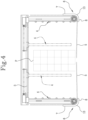
- the pick-up head “T” is lowered, and the first pair of compacting means 4 then moves to the compacting configuration approaching and compressing the sides of the group of tissue products as "P", as illustrated in Figure 4 .
- the unidirectional chains 5 slide from the disengaging position to the engaging position, thanks to the use of the pinions 9 (if present), and protrude from the horizontal stretch 8 of each guide 6 to form the cantilever supports for the bottom of the group of products "P".
- the first pair of compacting means 4 are tightened about the two sides of the group of tissue products "P” and push the products of the group to move towards each other, eliminating the empty spaces, at the same time the plurality of chains 5 slide progressively from the disengaging position to the engaging position below the bottom of the group of tissue products "P".
- the pick-up head "T” moves the group of tissue products "P” towards a subsequent processing station.
- this movement operation is more secure since the correct support of the group of tissue products "P" is ensured, as well as guaranteeing the prevention of damage to the groups.
- the invention also relates to a station "ST" for picking up a group of tissue products "P” comprising a pick-up head "T” as described above.
- the pick-up station “ST” may comprise any of the embodiments of the pick-up head "T” described above.
- the pick-up station “ST” also comprises a roller conveyor 21, positioned along a direction parallel to the second pair of compacting means 16, designed to move the group of tissue products "P" to the pick-up head "T".
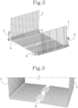
- the roller conveyor 21 has a U-shaped profile positioned below the level in which it lies which allows the unidirectional chains 5 to run between one roller and the next when they are in the engaging position.
- the unidirectional chains 5 of the pick-up head "T" have a smaller cross section than the U-shaped profiles positioned below the level on which the roller conveyor 21 lies.
- the roller conveyor has a number of rollers variable between twenty and forty rollers.
- the number of rollers in the station is defined on the basis of the dimensions of the group of tissue products "P" to be made.
- the pick-up station “ST” also comprises a front stopping device, not illustrated, which is movable between a lowered position wherein it is positioned below the roller conveyor 21, and a raised position wherein it extends beyond the level on which the roller conveyor 21 lies, for stopping the forward movement of the group of products.
- the roller conveyor 21 receives the products arriving from the roller conveyors (or from the belts) upstream and conveys them towards an area below the pick-up head "T".
- the products conveyed can be loose or already partly packaged together; in any case their size is greater than that of spacing of the roller conveyor 21 so that there is not even the risk of falling of even the smaller loose products.
- the stopping device When the products reach the area below the pick-up head "T", the stopping device extends beyond the level of the roller conveyor 21 to stop its forward movement.
- the device is formed by blades which protrude from the roller conveyor 21 in a perpendicular direction to it using the space between two adjacent rollers.
- the stopping device lowers, the pick-up head "T” lowers onto the group of tissue products "P", the pairs of compacting means 4 and 16 (the latter if present) pass from the open configuration to the compacting configuration and the unidirectional chains 5 pass from the disengaging position to the engaging position.
- the series of pinions 9 are arranged in such a way that each pinion 9 is interposed between one roller and the next; in this way when the unidirectional chains 5 move to the engaging position, they slide between one roller and the other of the roller conveyor 21.
- the unidirectional chains 5 are spaced at intervals equal to the spacing of each roller and they are offset in such a way as to allow them to be inserted between the rollers.
- the pick-up head "T” rises and moves the group of tissue products "P" compacted in this way to the next processing station, in particular towards the palletizing station.
- the release of the group of tissue products "P" in the palletizing station is performed by the sliding of the unidirectional chains 5 from the engaged position to the disengaged position and by the subsequent moving away of the first and second pairs of compacting means 4 and 16 (if present) from the group of tissue products "T" towards an open configuration.
- the pick-up head "T” may, after having released the group of tissue products "P", before picking up a second group of products, be moved to withdraw a cardboard panel from the stack and then position it on the layer of products just released.
- the invention achieves the above-mentioned aims, eliminating the drawbacks highlighted in the prior art.
- the structure of the pick-up head "T” allows a device to be obtained which is able to pick up tissue products "P" of any type, since the collaboration between the pairs of compacting means 4 and 16 and the unidirectional chains 5 also allows the picking up of non-compressible and/or sliding products, which makes the pick-up head "T” very versatile.
- the head “T" is also able to move and manage particularly high and unstable products such as, for example, kitchen rolls.
- the above-mentioned tissue products product "P" can be transported below the pick-up head “T” by flat belts (not illustrated) which are spaced from each other to form full lines (belts) and empty spaces parallel to each other and extending parallel to the direction in which the products are fed.
- the pick-up head “T” is rotated by 90° in such a way as to allow the picking up by means of the entrance of the chains 5 into the empty passages and then picking up the tissue products "P" between the "head” and "tail” of the group of belts.
- the pick-up head "T” is therefore able to pick up the tissue products "P" also if it is rotated by 90° by the robotic arm providing a high degree of versatility not only in terms of type of products which can be moved but also in terms of operating conditions of the head itself, that is to say, on picking up platforms also having different structures (strips or rolls, for example).
- a further advantage is due to the fact that the pick-up head "T" described in this way is less bulky and lighter than the traditional ones.
- the inverted "U" shaped structure or frame 14 in which the plurality of unidirectional chains 5 are inserted has a much smaller than the forks used in the prior art pick-up systems.
- a further advantage is the movement of the unidirectional chains 5 which, passing from a vertical position to a horizontal position sliding on a series of pinions 9, does not require movements towards and/or away of the support or frame 14 where they are inserted; this provides a system with a greater efficiency in terms of cycles per minute.
Landscapes
- Engineering & Computer Science (AREA)
- Mechanical Engineering (AREA)
- Robotics (AREA)
- Specific Conveyance Elements (AREA)
- Wrapping Of Specific Fragile Articles (AREA)
- Supplying Of Containers To The Packaging Station (AREA)
Claims (14)
- Aufnahmekopf (T) für Gruppen von Tissue-Produkten (P), umfassend:- eine Halterung (1), die mit einem Roboterarm (2) verbunden oder verbindbar ist, umfassend eine erste Verschiebeführung (3), die sich zwischen zwei entgegengesetzten Seiten der Halterung (1) erstreckt;- ein erstes Paar Verdichtungsmittel (4), die gegenständig zueinander angeordnet und hinführend zueinander und wegführend voneinander entlang der ersten Verschiebeführung (3) zwischen einer offenen Auslegung, in der ein jedes Verdichtungsmittel (4) an einem jeweiligen Ende der ersten Verschiebeführung (3) positioniert ist, und einer Verdichtungsauslegung, in der ein jedes Verdichtungsmittel (4) entlang der ersten Verschiebeführung (3) in einer gegenseitig geschlossenen Position positioniert ist, um die Gruppe von Tissue-Produkten (P) zu umgeben, verschiebbar sind;wobei er zudem Folgendes umfasst:- eine Vielzahl von unidirektionalen Ketten (5), wobei die unidirektionalen Ketten (5) außerhalb eines jeden Verdichtungsmittels (4) des ersten Paars positioniert sind, wobei die unidirektionalen Ketten (5) zwischen einer Freigabeposition, in der die unidirektionalen Ketten (5) vertikal relativ zu den Verdichtungsmitteln (4) positioniert sind, und einer Eingriffsposition, in der die unidirektionalen Ketten (5) mindestens teilweise senkrecht zu den Verdichtungsmitteln (4) positioniert sind, sodass sie unter der Gruppe von Tissue-Produkten (P) positioniert sind und eine auskragende Halterung definieren, verschiebbar sind;- eine Vielzahl von Führungen (6), die mit jeweiligen unidirektionalen Ketten (5) der Vielzahl assoziiert sind, wobei eine jede Führung (6) ein vertikales Teilstück (7) und ein horizontales Teilstück (8) aufweist, die ausgestaltet sind, um das Verschieben der unidirektionalen Ketten (5) so zu lenken, dass die Ketten (5) in der Eingriffsposition über eine Endkante des horizontalen Teilstücks (8) der Führung (6) hinausragen, sodass die auskragende Halterung ausgestaltet ist, um den Boden der Gruppe von Tissue-Produkten (P) während einer Bewegung der Gruppe von Tissue-Produkten (P) von einer Bearbeitungsstation zur anderen zu halten, wenn sich das erste Paar Verdichtungsmittel (4) in der Verdichtungsauslegung befindet, dadurch gekennzeichnet, dass die unidirektionalen Ketten (5) voneinander unterschiedliche Längen aufweisen, wobei zumindest eine erste Gruppe von unidirektionalen Ketten (5) eine Länge aufweist, die geringer ist als mindestens eine zweite Gruppe unidirektionaler Ketten (5), sodass unterschiedliche Ausdehnungen in der Eingriffsposition unter der Gruppe von Tissue-Produkten (P) definiert werden.
- Aufnahmekopf (T) nach Anspruch 1, wobei die unidirektionalen Ketten (5) eine leichte Krümmung aufweisen, die ausgestaltet ist, um ein Biegen nach unten der unidirektionalen Ketten (5) aufgrund des Gewichts der Gruppe von Tissue-Produkten (P) zu vermeiden, wenn sich die Vielzahl von unidirektionalen Ketten (5) in der Eingriffsposition befindet.
- Aufnahmekopf (T) nach Anspruch 1 oder 2, wobei sich eine jede der unidirektionalen Ketten (5) in der Eingriffsposition bis zu oder in die Nähe einer Mittelebene erstreckt, die parallel zu den beiden entgegengesetzten Seiten der Halterung (1) verläuft.
- Aufnahmekopf (T) nach einem der vorhergehenden Ansprüche, wobei die jeweiligen unidirektionalen Ketten (5) entgegengesetzt zur Mittelebenen in der Eingriffsposition eine Ausdehnung aufweisen, sodass ein Spalt (10) zwischen den unidirektionalen Ketten (5) zwischen 30 mm und 50 mm definiert wird, wobei der Spalt (10) vorzugsweise 30 mm beträgt.
- Aufnahmekopf (T) nach einem der vorhergehenden Ansprüche, wobei die Vielzahl von unidirektionalen Ketten (5) von mindestens einem Steller (11 oder 12) bewegt wird.
- Aufnahmekopf (T) nach einem der vorhergehenden Ansprüche, umfassend eine Reihe von Ritzeln (9), die eine Anzahl von Ritzeln (9) umfassen, die gleich der Anzahl der unidirektionalen Ketten (5) ist, wobei ein jedes der Ritzel (9) in der Nähe der Führungen (6) positioniert und ausgestaltet ist, um die unidirektionalen Ketten (5) während des Wechsels von der Freigabeposition in die Eingriffsposition und umgekehrt zu lenken, wobei eine jede unidirektionale Kette (5) zwischen der jeweiligen Führung (6) und dem jeweiligen Ritzel (9) eingesetzt ist.
- Aufnahmekopf (T) nach Anspruch 6, wobei das vertikale Teilstück (7) und das horizontale Teilstück (8) der Führung (6) durch ein gekrümmtes Teilstück (13) zusammengefügt sind, das sich mindestens entlang eines kreisförmigen Bogens eines jeweiligen Ritzels (9) erstreckt.
- Aufnahmekopf (T) nach einem der vorhergehenden Ansprüche, wobei die unidirektionalen Ketten (5) in einer Freigabeposition parallel zum ersten Paar von Verdichtungsmitteln (4) und entlang einer Halterung in der Form eines umgekehrten "U" außerhalb eines jeden Verdichtungsmittels des ersten Paars (4) positioniert sind.
- Aufnahmekopf (T) nach einem der vorhergehenden Ansprüche, wobei die Halterung (1) auch eine zweite Verschiebeführung (17) umfasst, die rechtwinkelig zur ersten Verschiebeführung (4) angeordnet ist und sich zwischen weiteren zwei entgegengesetzten Seiten der Halterung (1) erstreckt, wobei der Aufnahmekopf (T) auch ein zweites Paar von Verdichtungsmitteln (16) umfasst, die gegenständig zueinander positioniert und entlang der zweiten Führung (17) der Halterung (1) verschiebbar sind, wobei das zweite Paar von Verdichtungsmitteln (16) zwischen einer offenen Auslegung, in der ein jedes Verdichtungsmittel (16) an einem jeweiligen Ende der zweiten Führung (17) positioniert ist, und einer Verdichtungsauslegung, in der die Verdichtungsmittel (16) entlang der zweiten Führung (17) positioniert sind, um die Gruppe von Tissue-Produkten (P) zu umgeben, bewegbar sind.
- Aufnahmekopf (T) nach Anspruch 9, wobei ein jedes Verdichtungsmittel des zweiten Paars (16) mindestens zwei Saugnäpfe (19) umfasst, die an unteren Enden der Verdichtungsmittel des zweiten Paars (16) befindlich und so ausgelegt sind, dass sie an einer Pappeklappe haften, die zwischen einer Schicht und der nächsten einer Gruppe von Tissue-Produkten (P) zu positionieren ist.
- Aufnahmekopf (T) nach Anspruch 10, wobei die Saugnäpfe (19) ausgelegt sind, um sich zwischen einer angehobenen Position und einer abgesenkten Position entlang der Verdichtungsmittel des zweiten Paars (16) zu bewegen.
- Aufnahmekopf (T) nach einem der Ansprüche 9 bis 11, wobei das zweite Paar von Verdichtungsmitteln (16) Sensoren (20) umfasst, die ausgelegt sind, um eine zwischen einer Schicht und der nächsten der Gruppe von Tissue-Produkten (P) zu positionierende Pappeklappe zu erkennen, wobei die Sensoren (20) vorzugsweise ausgelegt sind, um eine Anwesenheitshöhe der Pappeklappe zu messen.
- Aufnahmestation (ST) für eine Gruppe von Tissue-Produkten, umfassend:- einen Aufnahmekopf (T) nach einem der vorhergehenden Ansprüche;- einen Walzenförderer (21), der ausgestaltet ist, um die Gruppe von Tissue-Produkten (P), die zum Aufnahmekopf (T) vorgeschoben werden, zu bewegen;- eine frontseitige Stoppvorrichtung, die zwischen einer abgesenkten Position, in der die Stoppvorrichtung unter dem Walzenförderer (21) positioniert ist, und einer angehobenen Position, in der sich die Stoppvorrichtung jenseits eines Niveaus erstreckt, auf dem der Walzenförderer (21) liegt, sodass die Vorwärtsbewegung der Gruppe von Tissue-Produkten (P) in einer Position unter dem Aufnahmekopf (T) blockiert wird, bewegbar ist.
- Aufnahmestation (ST) nach Anspruch 13, wobei der Walzenförderer (21) ein U-förmiges Profil aufweist, das unter dem Niveau, auf dem der Walzenförderer (21) liegt, bewegbar ist, und eine Teilung aufweist, die der der Vielzahl von unidirektionalen Ketten (5) gleicht, sodass das Verschieben der Vielzahl von unidirektionalen Ketten (5) in einem Raum zwischen einer Walze und der nächsten erlaubt wird, wenn sich die Vielzahl von unidirektionalen Ketten (5) in der Eingriffsposition befindet.
Applications Claiming Priority (2)
| Application Number | Priority Date | Filing Date | Title |
|---|---|---|---|
| IT102019000012939A IT201900012939A1 (it) | 2019-07-25 | 2019-07-25 | Testa e stazione di prelievo di un gruppo di prodotti. |
| PCT/IB2020/056891 WO2021014377A1 (en) | 2019-07-25 | 2020-07-22 | Head and station for picking up a group of products. |
Publications (3)
| Publication Number | Publication Date |
|---|---|
| EP4003885A1 EP4003885A1 (de) | 2022-06-01 |
| EP4003885C0 EP4003885C0 (de) | 2023-09-13 |
| EP4003885B1 true EP4003885B1 (de) | 2023-09-13 |
Family
ID=68582275
Family Applications (1)
| Application Number | Title | Priority Date | Filing Date |
|---|---|---|---|
| EP20739838.9A Active EP4003885B1 (de) | 2019-07-25 | 2020-07-22 | Kopf und station zum aufnehmen einer gruppe von produkten |
Country Status (4)
| Country | Link |
|---|---|
| US (1) | US12370695B2 (de) |
| EP (1) | EP4003885B1 (de) |
| IT (1) | IT201900012939A1 (de) |
| WO (1) | WO2021014377A1 (de) |
Families Citing this family (2)
| Publication number | Priority date | Publication date | Assignee | Title |
|---|---|---|---|---|
| EP4112513B1 (de) * | 2021-06-29 | 2024-05-29 | Schiller Automatisierungstechnik GmbH | System mit einem greifer |
| CN117104901B (zh) * | 2023-10-25 | 2024-01-12 | 长沙润伟机电科技有限责任公司 | 应用于自动打包生产线的自动化码垛装置 |
Family Cites Families (3)
| Publication number | Priority date | Publication date | Assignee | Title |
|---|---|---|---|---|
| US20050220599A1 (en) * | 2004-04-02 | 2005-10-06 | Job Matthew A | Clamshell and fork-style material handling apparatus |
| EP2508452A1 (de) * | 2011-04-04 | 2012-10-10 | Elettric 80 S.p.A. | Palletiervorrichtung und Verfahren |
| WO2014090275A1 (en) * | 2012-12-10 | 2014-06-19 | Skala Robotech As | Apparatus, system and method for conveying goods |
-
2019
- 2019-07-25 IT IT102019000012939A patent/IT201900012939A1/it unknown
-
2020
- 2020-07-22 WO PCT/IB2020/056891 patent/WO2021014377A1/en not_active Ceased
- 2020-07-22 US US17/627,932 patent/US12370695B2/en active Active
- 2020-07-22 EP EP20739838.9A patent/EP4003885B1/de active Active
Also Published As
| Publication number | Publication date |
|---|---|
| US12370695B2 (en) | 2025-07-29 |
| WO2021014377A1 (en) | 2021-01-28 |
| IT201900012939A1 (it) | 2021-01-25 |
| EP4003885A1 (de) | 2022-06-01 |
| US20220258359A1 (en) | 2022-08-18 |
| EP4003885C0 (de) | 2023-09-13 |
Similar Documents
| Publication | Publication Date | Title |
|---|---|---|
| EP3068712B1 (de) | Palettieranlage und verfahren zum palettieren | |
| US8714904B2 (en) | Apparatus for lifting a group of containers or the like | |
| US20120027555A1 (en) | Palletizer with box layer preparation | |
| US4498381A (en) | Signature transfer vehicle with stack clamping mechanism | |
| KR20140064773A (ko) | 물품을 처리하기 위한 방법 및 선형 장치 | |
| EP4003885B1 (de) | Kopf und station zum aufnehmen einer gruppe von produkten | |
| CN210140314U (zh) | 一种垂直收纸码垛设备 | |
| JP6611111B1 (ja) | 集積搬送機 | |
| CN113148744A (zh) | 用于形成片材堆的片材堆垛机和方法 | |
| CN104364173A (zh) | 用于在相邻的模块之间传送制品的层的装置和方法 | |
| NO863543L (no) | Innretning for palettering av stabler. | |
| JP2020152483A (ja) | 搬送機 | |
| US4397599A (en) | Descending accumulator for automatic case packer | |
| US4765452A (en) | Device in a machine handling package units | |
| US20070107385A1 (en) | Unit and method for forming packs of products for a packaging machine | |
| EP0315807A1 (de) | Verfahren und Vorrichtung für das Stapeln von Artikeln und das Zuführen der Stapel an einen Abfuhrbereich | |
| CN217348423U (zh) | 一种包装箱排列整形辊道机及码垛系统 | |
| CN105819017B (zh) | 一种包装机 | |
| EP1899228B1 (de) | Verfahren und vorrichtung zur bildung und abführung von geordneten gruppen von produkten, insbesondere papierrollen | |
| CH687518A5 (it) | Dispositivo per convogliare articoli, particolarmente per impianti automatici di confezionamento. | |
| EP3147244B1 (de) | Blattstapel- und verfahren zur bildung von versetzten stapelbündeln | |
| CN208683856U (zh) | 一种带侧板能升降的输送平台装置 | |
| CN215623036U (zh) | 一种摆渡辊道 | |
| JPH0532344A (ja) | 層状単位の運搬手段と層状単位の運搬および搬出方法 | |
| US9371200B2 (en) | Device the conveying and handling of products |
Legal Events
| Date | Code | Title | Description |
|---|---|---|---|
| STAA | Information on the status of an ep patent application or granted ep patent |
Free format text: STATUS: UNKNOWN |
|
| STAA | Information on the status of an ep patent application or granted ep patent |
Free format text: STATUS: THE INTERNATIONAL PUBLICATION HAS BEEN MADE |
|
| PUAI | Public reference made under article 153(3) epc to a published international application that has entered the european phase |
Free format text: ORIGINAL CODE: 0009012 |
|
| STAA | Information on the status of an ep patent application or granted ep patent |
Free format text: STATUS: REQUEST FOR EXAMINATION WAS MADE |
|
| 17P | Request for examination filed |
Effective date: 20220110 |
|
| AK | Designated contracting states |
Kind code of ref document: A1 Designated state(s): AL AT BE BG CH CY CZ DE DK EE ES FI FR GB GR HR HU IE IS IT LI LT LU LV MC MK MT NL NO PL PT RO RS SE SI SK SM TR |
|
| DAV | Request for validation of the european patent (deleted) | ||
| DAX | Request for extension of the european patent (deleted) | ||
| GRAP | Despatch of communication of intention to grant a patent |
Free format text: ORIGINAL CODE: EPIDOSNIGR1 |
|
| STAA | Information on the status of an ep patent application or granted ep patent |
Free format text: STATUS: GRANT OF PATENT IS INTENDED |
|
| INTG | Intention to grant announced |
Effective date: 20230411 |
|
| P01 | Opt-out of the competence of the unified patent court (upc) registered |
Effective date: 20230529 |
|
| GRAS | Grant fee paid |
Free format text: ORIGINAL CODE: EPIDOSNIGR3 |
|
| GRAA | (expected) grant |
Free format text: ORIGINAL CODE: 0009210 |
|
| STAA | Information on the status of an ep patent application or granted ep patent |
Free format text: STATUS: THE PATENT HAS BEEN GRANTED |
|
| AK | Designated contracting states |
Kind code of ref document: B1 Designated state(s): AL AT BE BG CH CY CZ DE DK EE ES FI FR GB GR HR HU IE IS IT LI LT LU LV MC MK MT NL NO PL PT RO RS SE SI SK SM TR |
|
| REG | Reference to a national code |
Ref country code: CH Ref legal event code: EP |
|
| REG | Reference to a national code |
Ref country code: DE Ref legal event code: R096 Ref document number: 602020017666 Country of ref document: DE |
|
| REG | Reference to a national code |
Ref country code: IE Ref legal event code: FG4D |
|
| U01 | Request for unitary effect filed |
Effective date: 20231009 |
|
| P04 | Withdrawal of opt-out of the competence of the unified patent court (upc) registered |
Effective date: 20231014 |
|
| U07 | Unitary effect registered |
Designated state(s): AT BE BG DE DK EE FI FR IT LT LU LV MT NL PT SE SI Effective date: 20231018 |
|
| PG25 | Lapsed in a contracting state [announced via postgrant information from national office to epo] |
Ref country code: GR Free format text: LAPSE BECAUSE OF FAILURE TO SUBMIT A TRANSLATION OF THE DESCRIPTION OR TO PAY THE FEE WITHIN THE PRESCRIBED TIME-LIMIT Effective date: 20231214 |
|
| PG25 | Lapsed in a contracting state [announced via postgrant information from national office to epo] |
Ref country code: RS Free format text: LAPSE BECAUSE OF FAILURE TO SUBMIT A TRANSLATION OF THE DESCRIPTION OR TO PAY THE FEE WITHIN THE PRESCRIBED TIME-LIMIT Effective date: 20230913 Ref country code: NO Free format text: LAPSE BECAUSE OF FAILURE TO SUBMIT A TRANSLATION OF THE DESCRIPTION OR TO PAY THE FEE WITHIN THE PRESCRIBED TIME-LIMIT Effective date: 20231213 Ref country code: HR Free format text: LAPSE BECAUSE OF FAILURE TO SUBMIT A TRANSLATION OF THE DESCRIPTION OR TO PAY THE FEE WITHIN THE PRESCRIBED TIME-LIMIT Effective date: 20230913 Ref country code: GR Free format text: LAPSE BECAUSE OF FAILURE TO SUBMIT A TRANSLATION OF THE DESCRIPTION OR TO PAY THE FEE WITHIN THE PRESCRIBED TIME-LIMIT Effective date: 20231214 |
|
| PG25 | Lapsed in a contracting state [announced via postgrant information from national office to epo] |
Ref country code: IS Free format text: LAPSE BECAUSE OF FAILURE TO SUBMIT A TRANSLATION OF THE DESCRIPTION OR TO PAY THE FEE WITHIN THE PRESCRIBED TIME-LIMIT Effective date: 20240113 |
|
| PG25 | Lapsed in a contracting state [announced via postgrant information from national office to epo] |
Ref country code: ES Free format text: LAPSE BECAUSE OF FAILURE TO SUBMIT A TRANSLATION OF THE DESCRIPTION OR TO PAY THE FEE WITHIN THE PRESCRIBED TIME-LIMIT Effective date: 20230913 |
|
| PG25 | Lapsed in a contracting state [announced via postgrant information from national office to epo] |
Ref country code: SM Free format text: LAPSE BECAUSE OF FAILURE TO SUBMIT A TRANSLATION OF THE DESCRIPTION OR TO PAY THE FEE WITHIN THE PRESCRIBED TIME-LIMIT Effective date: 20230913 Ref country code: RO Free format text: LAPSE BECAUSE OF FAILURE TO SUBMIT A TRANSLATION OF THE DESCRIPTION OR TO PAY THE FEE WITHIN THE PRESCRIBED TIME-LIMIT Effective date: 20230913 Ref country code: IS Free format text: LAPSE BECAUSE OF FAILURE TO SUBMIT A TRANSLATION OF THE DESCRIPTION OR TO PAY THE FEE WITHIN THE PRESCRIBED TIME-LIMIT Effective date: 20240113 Ref country code: ES Free format text: LAPSE BECAUSE OF FAILURE TO SUBMIT A TRANSLATION OF THE DESCRIPTION OR TO PAY THE FEE WITHIN THE PRESCRIBED TIME-LIMIT Effective date: 20230913 Ref country code: CZ Free format text: LAPSE BECAUSE OF FAILURE TO SUBMIT A TRANSLATION OF THE DESCRIPTION OR TO PAY THE FEE WITHIN THE PRESCRIBED TIME-LIMIT Effective date: 20230913 Ref country code: SK Free format text: LAPSE BECAUSE OF FAILURE TO SUBMIT A TRANSLATION OF THE DESCRIPTION OR TO PAY THE FEE WITHIN THE PRESCRIBED TIME-LIMIT Effective date: 20230913 |
|
| PG25 | Lapsed in a contracting state [announced via postgrant information from national office to epo] |
Ref country code: PL Free format text: LAPSE BECAUSE OF FAILURE TO SUBMIT A TRANSLATION OF THE DESCRIPTION OR TO PAY THE FEE WITHIN THE PRESCRIBED TIME-LIMIT Effective date: 20230913 |
|
| REG | Reference to a national code |
Ref country code: DE Ref legal event code: R097 Ref document number: 602020017666 Country of ref document: DE |
|
| PLBE | No opposition filed within time limit |
Free format text: ORIGINAL CODE: 0009261 |
|
| STAA | Information on the status of an ep patent application or granted ep patent |
Free format text: STATUS: NO OPPOSITION FILED WITHIN TIME LIMIT |
|
| 26N | No opposition filed |
Effective date: 20240614 |
|
| U20 | Renewal fee for the european patent with unitary effect paid |
Year of fee payment: 5 Effective date: 20240717 |
|
| P05 | Withdrawal of opt-out of the competence of the unified patent court (upc) changed |
Free format text: CASE NUMBER: APP_580220/2023 Effective date: 20231018 |
|
| PG25 | Lapsed in a contracting state [announced via postgrant information from national office to epo] |
Ref country code: MC Free format text: LAPSE BECAUSE OF FAILURE TO SUBMIT A TRANSLATION OF THE DESCRIPTION OR TO PAY THE FEE WITHIN THE PRESCRIBED TIME-LIMIT Effective date: 20230913 |
|
| REG | Reference to a national code |
Ref country code: CH Ref legal event code: PL |
|
| PG25 | Lapsed in a contracting state [announced via postgrant information from national office to epo] |
Ref country code: CH Free format text: LAPSE BECAUSE OF NON-PAYMENT OF DUE FEES Effective date: 20240731 |
|
| PG25 | Lapsed in a contracting state [announced via postgrant information from national office to epo] |
Ref country code: IE Free format text: LAPSE BECAUSE OF NON-PAYMENT OF DUE FEES Effective date: 20240722 |
|
| U20 | Renewal fee for the european patent with unitary effect paid |
Year of fee payment: 6 Effective date: 20250723 |
|
| PGFP | Annual fee paid to national office [announced via postgrant information from national office to epo] |
Ref country code: GB Payment date: 20250724 Year of fee payment: 6 |
|
| PG25 | Lapsed in a contracting state [announced via postgrant information from national office to epo] |
Ref country code: CY Free format text: LAPSE BECAUSE OF FAILURE TO SUBMIT A TRANSLATION OF THE DESCRIPTION OR TO PAY THE FEE WITHIN THE PRESCRIBED TIME-LIMIT; INVALID AB INITIO Effective date: 20200722 |
|
| PG25 | Lapsed in a contracting state [announced via postgrant information from national office to epo] |
Ref country code: HU Free format text: LAPSE BECAUSE OF FAILURE TO SUBMIT A TRANSLATION OF THE DESCRIPTION OR TO PAY THE FEE WITHIN THE PRESCRIBED TIME-LIMIT; INVALID AB INITIO Effective date: 20200722 |