EP4004241B1 - Installation et procédé de finition de peaux - Google Patents
Installation et procédé de finition de peaux Download PDFInfo
- Publication number
- EP4004241B1 EP4004241B1 EP20751667.5A EP20751667A EP4004241B1 EP 4004241 B1 EP4004241 B1 EP 4004241B1 EP 20751667 A EP20751667 A EP 20751667A EP 4004241 B1 EP4004241 B1 EP 4004241B1
- Authority
- EP
- European Patent Office
- Prior art keywords
- layer
- skin
- transport plate
- plant according
- skins
- Prior art date
- Legal status (The legal status is an assumption and is not a legal conclusion. Google has not performed a legal analysis and makes no representation as to the accuracy of the status listed.)
- Active
Links
Images



Classifications
-
- B—PERFORMING OPERATIONS; TRANSPORTING
- B32—LAYERED PRODUCTS
- B32B—LAYERED PRODUCTS, i.e. PRODUCTS BUILT-UP OF STRATA OF FLAT OR NON-FLAT, e.g. CELLULAR OR HONEYCOMB, FORM
- B32B7/00—Layered products characterised by the relation between layers; Layered products characterised by the relative orientation of features between layers, or by the relative values of a measurable parameter between layers, i.e. products comprising layers having different physical, chemical or physicochemical properties; Layered products characterised by the interconnection of layers
- B32B7/04—Interconnection of layers
- B32B7/12—Interconnection of layers using interposed adhesives or interposed materials with bonding properties
-
- B—PERFORMING OPERATIONS; TRANSPORTING
- B32—LAYERED PRODUCTS
- B32B—LAYERED PRODUCTS, i.e. PRODUCTS BUILT-UP OF STRATA OF FLAT OR NON-FLAT, e.g. CELLULAR OR HONEYCOMB, FORM
- B32B27/00—Layered products comprising a layer of synthetic resin
- B32B27/40—Layered products comprising a layer of synthetic resin comprising polyurethanes
-
- B—PERFORMING OPERATIONS; TRANSPORTING
- B32—LAYERED PRODUCTS
- B32B—LAYERED PRODUCTS, i.e. PRODUCTS BUILT-UP OF STRATA OF FLAT OR NON-FLAT, e.g. CELLULAR OR HONEYCOMB, FORM
- B32B37/00—Methods or apparatus for laminating, e.g. by curing or by ultrasonic bonding
- B32B37/12—Methods or apparatus for laminating, e.g. by curing or by ultrasonic bonding characterised by using adhesives
-
- B—PERFORMING OPERATIONS; TRANSPORTING
- B32—LAYERED PRODUCTS
- B32B—LAYERED PRODUCTS, i.e. PRODUCTS BUILT-UP OF STRATA OF FLAT OR NON-FLAT, e.g. CELLULAR OR HONEYCOMB, FORM
- B32B9/00—Layered products comprising a layer of a particular substance not covered by groups B32B11/00 - B32B29/00
- B32B9/02—Layered products comprising a layer of a particular substance not covered by groups B32B11/00 - B32B29/00 comprising animal or vegetable substances, e.g. cork, bamboo, starch
- B32B9/025—Layered products comprising a layer of a particular substance not covered by groups B32B11/00 - B32B29/00 comprising animal or vegetable substances, e.g. cork, bamboo, starch comprising leather
-
- B—PERFORMING OPERATIONS; TRANSPORTING
- B32—LAYERED PRODUCTS
- B32B—LAYERED PRODUCTS, i.e. PRODUCTS BUILT-UP OF STRATA OF FLAT OR NON-FLAT, e.g. CELLULAR OR HONEYCOMB, FORM
- B32B9/00—Layered products comprising a layer of a particular substance not covered by groups B32B11/00 - B32B29/00
- B32B9/04—Layered products comprising a layer of a particular substance not covered by groups B32B11/00 - B32B29/00 comprising such particular substance as the main or only constituent of a layer, which is next to another layer of the same or of a different material
- B32B9/045—Layered products comprising a layer of a particular substance not covered by groups B32B11/00 - B32B29/00 comprising such particular substance as the main or only constituent of a layer, which is next to another layer of the same or of a different material of synthetic resin
-
- C—CHEMISTRY; METALLURGY
- C09—DYES; PAINTS; POLISHES; NATURAL RESINS; ADHESIVES; COMPOSITIONS NOT OTHERWISE PROVIDED FOR; APPLICATIONS OF MATERIALS NOT OTHERWISE PROVIDED FOR
- C09D—COATING COMPOSITIONS, e.g. PAINTS, VARNISHES OR LACQUERS; FILLING PASTES; CHEMICAL PAINT OR INK REMOVERS; INKS; CORRECTING FLUIDS; WOODSTAINS; PASTES OR SOLIDS FOR COLOURING OR PRINTING; USE OF MATERIALS THEREFOR
- C09D175/00—Coating compositions based on polyureas or polyurethanes; Coating compositions based on derivatives of such polymers
- C09D175/04—Polyurethanes
Definitions
- the invention relates to a plant for ennobling skins and leather in general.
- a process for ennobling skins that can be carried out with a similar plant is also the object of the invention.
- the ennobling of a skin in particular of the innermost and less valuable layers, provides for surface treatments aimed at improving the technical and aesthetic characteristics of the skin thus processed.
- an ennobling plant comprises the following operating zones:
- a first important limitation is given by the fact that the pressing systems applied to eliminate the bubbles between the skin and the polyurethane finishing layer, in order to optimize the adhesion between said layers, may not be effective, with the consequent formation of unwanted 'orange peel' zones.
- a second limitation of the known plants is given by the overall dimensions of a plant, since generally it also comprises a waiting zone or a parallel path for cooling the treated skins up to an ambient temperature which allows their superimposition on a stand.
- the patent document GB 1265951 describes a method of reinforcing animal skins comprising laying out a series of skins on a conveyor belt, applying a continuous web of flexible material to cover the skins on the conveyor belt after coating the skins, or the web, with an adhesive material to secure them together, and stripping the resultant composite from the conveyor belt; not even this document addresses the limitations of the prior art.
- the task of the present invention is to develop a plant for ennobling skins capable of obviating the above mentioned drawbacks and limitations of the prior art.
- an object of the invention is to develop a process for the realisation of ennobled skins capable of obviating the limitations of the processes carried out with the plants of the known type.
- An important object of the invention is to develop a plant which allows to realise ennobled skins with less superficial imperfections than the similar ennobled skins obtained with the known plants.
- a similar object of the invention is to develop a process which allows to realise ennobled skins with less superficial imperfections than the similar ennobled skins obtained with the known processes.
- a further object of the invention is to develop a system capable of ensuring a correct cooling of the ennobled skins with a smaller overall dimension than the known plants.
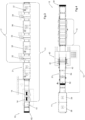
- Said plant 10 comprises:
- the first group 11 comprises:
- the second group 12 comprises:
- the layer for support and for shaping of the finishing 16 , the finishing layer 18 and the layer of adhesive 19 are well highlighted in figure 9 .
- the transport plates 14 are prepared with the layer for support and for shaping 16 in separate machines, which machines are to be understood of known type.
- the third group 13 comprises:
- the transport plate 14, also called the 'matrix' in jargon, is made up, for example, of an aluminium foil 1.5 meters long, 1.5 meters wide and 2.5 millimetres thick.
- the plant 10 comprises advancement means 50 for the transport plates 14 .
- Said advancement means 50 comprise, for example, belt or roller type conveyors.
- Said advancement means 50 are configured to move the transport plates 14 in a same direction and in a same forward direction, defining a forward path for the plates 14 themselves.
- Said advancement means 50 are configured to move the transport plates 14 keeping them at the same height from the ground for the entire forward path.
- the layer for support and for shaping 16 comprises, for example, a silicone layer.
- Said layer for support and for shaping 16 has a thickness of 2.5 mm, for example.
- Said layer for support and for shaping 16 defines an outline of the finish to be reproduced on a skin to be ennobled, as well as it defines the patterns of the surface finishes to be reproduced on the same skin to be ennobled, for example patterns imitating a crocodile skin.
- the first group 11 also comprises a first heating station 31 for pre-heating the layer for support and for shaping 16 .
- Said first heating station 31 comprises, for example, a diathermic oil heating station.
- the temperature is of great importance especially in the first spraying that is made with the polyurethane on the transport plate 14 .
- the first heating station 31 is therefore configured to raise the temperature of a transport plate 14 up to a value ranging between 80°C and 105°C.
- said first heating station 31 is configured to raise the temperature of a transport plate 14 up to a value ranging between 95°C and 100°C.
- the means 17 for realising a finishing layer 18 comprise, in the present embodiment, three pigmentation booths 32, 33 and 34 respectively, arranged in series, each of which is followed by a corresponding second heating station 35, 36 and 37 respectively.
- Said pigmentation booths perform hot spraying operations.
- the plant 10 according to the invention is to be understood as comprising a single pigmentation booth followed by a single corresponding second heating station.
- the plant 10 according to the invention is to be understood as comprising also two or more pigmentation booths, each followed by a corresponding second heating station.
- the pigmentation booths 32 , 33 and 34 are configured for polyurethane spraying.
- the finishing layer 18 is therefore a pigmented polyurethane layer.
- the finishing layer 18 is sprayed onto the silicone layer for support and for shaping 16 ; in this way, the finishing layer 18 takes on the shape and the patterns of the layer for support and for shaping 16 .
- the first group 11 also comprises one or more cooling stations, for example two cooling stations 38 and 39 .
- the cooling stations 38 and 39 are configured to bring the transport plates 14 , with the layer for support and for shaping 16 and the finishing layer 18 , to a temperature lower than 45°C.
- said cooling stations 38 and 39 are configured to bring the transport plates 14 , with the layer for support and for shaping 16 and the finishing layer 18 , to a temperature ranging from 25°C to 35°C.
- the deposition means 40 comprise a spreading machine 41 , for example of the type with spreading roller.
- the layer of adhesive 19 is understood to be made with a liquid adhesive, for example a water-based adhesive.
- composition of said adhesive depends, in a known way, on the thickness of the finishing layer 18 .
- the second deposition means 40 also comprise one or more unloading conveyors 42 for preparing the skin 20 for the positioning on the transport plate 14 , as better described below.
- Said second deposition means 40 are positioned at a higher height than the advancement means of the transport plates 14 .
- the positioning means 21 for positioning a skin 20 on a transport plate 14 comprise overturning means 51 configured to overturn a skin 20 on which a layer of adhesive 19 has been deposited.
- said overturning means 51 are configured to overturn a skin 20 from a spreading arrangement, in which the layer of adhesive 19 faces upwards, to a joining arrangement, in which the layer of adhesive 19 faces a transport plate 14 .
- the overturning means 51 comprise an overturning conveyor 52 in turn comprising a belt 53 moved between two end rollers 54 and 55 respectively.
- Said overturning means 51 are positioned above an intermediate conveyor 56 .
- Said intermediate conveyor 56 is understood to be a belt conveyor, or roller conveyor, or other conveyor configured for the advancement of a flat body, such as a plate, to be understood of a type known per se.
- One of said end rollers 54 causes a skin 20 to descend on an underlying transport plate 14 .
- Said end roller 54 clearly visible in figures 6, 7 and 8 , has a perforated cylindrical wall 57 , defining inside a chamber 59 which perforated cylindrical wall 57 has a matrix of through holes 58 .
- the end roller 54 is connected to suction means configured to cause a vacuum inside the chamber 59 .
- the belt 53 is breathable, i.e. it allows the passage of air.
- the suction means retain a skin 20 which is at the end roller 54 , as exemplified in figure 8 .
- the suction means are to be understood of a type known per se, such as for example an air suction pump.
- Said air suction pump is connected with a rotating joint at the rotation axis of the end suction roller 54 .
- the belt 53 is constituted, for example, by a perforated carpet, or by a net.
- the rotation of the end suction roller 54 causes the equal rotation of the skin 20 which is thus overturned and unloaded below the overturning conveyor 52 above a transport plate 14 which is transiting in a synchronized way.
- the end suction roller 54 also comprises sealing means configured to cause a suction arc 54a , as shown in figure 8 , of the end roller itself, i.e. a predetermined rotation angle along which the end suction roller 54 expresses its capability of retaining a skin 20 , and outside of which the end suction roller 54 does not act.
- Said sealing means comprise, by way of example, two longitudinal sealing bodies 60 and 61 , an upper and a lower one, supported by an anti-suction casing 62 .
- the longitudinal sealing bodies 60 and 61 are positioned so that the suction arc 54a of the end suction roller 54 has an amplitude 54b of not less than 180° and of substantially 180°.
- the anti-suction casing 62 is to be understood as to be supported by a supporting frame.
- a synchronization conveyor 64 is interposed between the overturning means 51 and the second deposition means 40 .
- Said synchronization conveyor 64 is driven alternatively substantially at two speeds:
- synchronization conveyor 64 operates for a first time interval at the first speed and for a second time interval, following the first time interval, at the second speed.
- a first speed can be for example 9 meters per minute.
- a second speed can range, for example, between 20 meters per minute and 45 meters per minute.
- the overturning conveyor 52 is in turn also driven alternately at two speeds:
- overturning conveyor 52 operates for a first time interval at the first speed and for a second time interval, following the first time interval, at the second speed.
- a first speed can range, for example, between 20 meters per minute and 45 meters per minute.
- a second speed can be for example 5 meters per minute.
- the synchronization conveyor 64 when it receives a skin 20 from the unloading conveyor 42 operates as follows:
- the production rate is optimized without stressing the skins 20 .
- the speed of the belt 53 of the overturning conveyor 52 of the overturning means and the advancement speed of the advancement means 50, and specifically of the intermediate conveyor 56, which make the transport plates 14 advance, are coordinated in such a way as to tension a skin 20 which is overturned by the belt 53 above a transport plate 14 ; this skin 20 is tensioned by a higher speed of the transport plate 14 with respect to the skin 20 .
- the positioning means 21 comprise, in addition to the overturning means 51, also an auxiliary smoothing calender 70, exemplified in figure 5 , configured to ensure that the skin 20 fully adheres to the transport plate 14 .
- the third group 13 comprises four presses 25, 25a, 25b and 25c respectively.
- a press 25 is described below, meaning thereby that the other presses are equal.
- the lower plane 26 is constituted by a movable, heated plate, driven vertically by the closing and opening means 28 .
- the upper plane 27 comprises a fixed plate.
- the closing and opening means 28 comprise, for example, a series of hydraulic cylinders 28a , configured to shift the lower plane 26 in a vertical direction.
- the hydraulic cylinders allow an opening and closing speed of the press much higher than the pneumatically operated presses of the known type; moreover, said hydraulic cylinders allow higher pressures to be achieved with a greater operating speed, to the full advantage of the production rates of the plant 10 .
- the thrust levelling layer 29 is fixed to the upper plane 27 .
- Said thrust levelling layer 29 is made, for example and not exclusively, of felt.
- Said levelling layer 29 can have a thickness between 5 millimetres and 10 millimetres, for example 7 millimetres.
- the two lower 26 and upper 27 planes are made of steel.
- the levelling layer 29 that is the felt layer, is configured in such a way as to yield adapting to the surface shapes of the skin 20 thus distributing the thrust between the two planes 26 and 27 uniformly over the entire surface of the skin 20 being processed.
- the levelling layer 29 can comprise reinforcing layers, for example of cloth or other equivalent layer.
- the levelling layer 29 is kept in position and under tension by means of two opposed locking pliers, schematized in figure 9 and indicated therein with the numbers 27a and 27b .
- the reinforcing layers of the levelling layer 29 ensure that this does not break due to the action of the locking pliers 27a and 27b .
- the protective film 30 may comprise a fabric, or a non-woven fabric, or a combination of both.
- the protective film 30 comprises a porous protective fabric film.
- Said porous protective fabric film is made, for example, of a glassy material and impregnated with PTFE, for example with Teflon.
- Said protective film 30 creates a non-stick protective barrier of the polyurethane deposited on the transport plate 14 and not covered by the skin 20 ; in fact, when the skin 20 is pressed against the transport plate 14 inside a press 25 , the polyurethane that is present around the skin 20 , that is outside the area occupied by the skin 20 itself, could stick to the levelling layer 29 , i.e. to the felt layer, in a completely undesirable and harmful way.
- the protective film 30 which at the same time is also breathable, prevents the adhesion of the polyurethane to the levelling layer 29 , but allows the evaporation of humidity from the skin 20 .
- the humidity is discharged through the levelling layer 29 and goes into the environment.
- Each heat press 25 comprises a reel 30a of new protective film 30 and an opposite winding reel 30b for the used protective film.
- At least the winding reel 30b is driven by manual means, for example by means of a crank.
- the winding reel 30b is motor driven.
- the protective film 30 can be replaced automatically by activating the winding reel 30b ; the rotation of the winding reel 30b causes the winding of the used protective film 30 and the unwinding of a new protective film 30 which is placed below the felt layer in place of the used protective film.
- the hot press 25 is configured to operate with the lower plane 26 at a temperature between 85°C and 100°C.
- the hot press 25 is configured to operate with the lower plane 26 at a temperature between 90°C and 95°C.
- the hot press 25 is configured to operate with the upper plane 27 at a temperature of 70°C.
- the temperature of 70°C for the upper plane 27 causes the felt levelling layer 29 to dry, so that the humidity released by the skin 20 is not collected there.
- the hot press 25 causes the skin 20 to be glued, through the layer of adhesive 19 , on the finishing layer 18 , in polyurethane, which finishing layer 18 is sprayed on the layer for support and for shaping 16 , made of silicone.
- the hot press 25 is configured to operate at a pressure ranging between 1 kg/cm 2 and 3.5 kg/cm 2 ; preferably, the hot press 25 causes a pressure of 2 kg/cm 2 .
- the plant 10 according to the invention is configured to operate on two consecutive transport plates 14 ; this means that two transport plates 14 simultaneously receive the same treatment.
- each skin 20 with a corresponding transport plate 14 receives two pressing steps, each of which in a different hot press 25 .
- the plant 10 according to the invention described herein has four hot presses 25, 25a, 25b, 25c arranged in series.
- the plant 10 according to the invention can obviously be configured to operate on a single transport plate 14 and can therefore comprise two hot presses 25 instead of four.
- the plant 10 according to the invention is configured to operate on three or more consecutive transport plates 14 ; this means that three or more transport plates 14 simultaneously receive a same treatment.
- Each skin 20 then receives a first pressing operation at 2 kg/cm 2 for 15 seconds, followed by an intermediate evaporation step with the press open for 8 - 10 seconds, and then a second pressing operation for another 15 seconds.
- the plant 10 according to the invention can have two hot presses 25, each of which configured to operate two consecutive pressing operations on a same skin 20, with interposition of an opening interval of 8 - 10 seconds between the first pressing operation and the second pressing operation.
- a plant 10 according to the invention can be used performing a single pressing operation on a skin 20, lasting for a time ranging between 20 and 25 seconds, and preferably of about 20 seconds.
- the bubbles between the layer of adhesive 19 and the finishing layer 18 in polyurethane, which cause the imperfect adhesion between the skin and the polyurethane with consequent formation of "orange peel” defects on the skin, are the defect the elimination of which is aimed with the plant 10 according to the invention.
- the plant 10 according to the invention also comprises a return path 80 for the ennobled skins.
- Said return path 80 is schematized in figures 1, 2 , 3 and 4 and exemplified in figures 10 and 11 .
- Said return path 80 develops below the three groups first 11 , second 12 and third 13 .
- Said return path 80 comprises an initial lowering conveyor 81 located downstream of the third group 13 .
- the return path 80 also comprises a final lifting conveyor 82 located upstream of the first group 11 .
- the initial conveyor 81 is a belt type conveyor.
- Said initial conveyor 81 is configured to transfer one or more transport plates 14 from a first processing height to a second return height.
- Said initial conveyor 81 comprises means for varying the inclination thereof.
- Such means for varying the inclination comprise, by way of example, a rack system comprising on one side a fulcrum 81a for the frame of the initial conveyor 81 and on the opposite side an arched rack 81b meshed with a motorized pinion integral with the frame of the initial conveyor 81 .
- the final conveyor 82 is configured to transfer one or more transport plates 14 from the second return height to the first processing height.
- Said final conveyor 82 comprises means for varying the inclination thereof.
- Such means for varying the inclination comprise, by way of example, analogously to what described for the initial conveyor 81 , a rack system comprising on one side a fulcrum 82a for the frame of the final conveyor 82 and on the opposite side an arched rack 82b meshed with a motorized pinion integral with the frame of the final conveyor 82 .
- the return path 80 advantageously develops below the advancement means 50 which define the forward path.
- the return path 80 comprises a plurality of roller or belt conveyors arranged in series below the three groups first 11 , second 12 and third 13 , configured to move the transport plates 14, carrying the ennobled skins 20, from the initial conveyor 81 to the final conveyor 82 .
- the return path 80 is made at a speed such as to allow drying and cooling of the ennobled skins 20 such that the skins 20 are superimposable one onto the other on a stand without them improperly adhering one to the other.
- the invention also relates to a process for ennobling skins.
- This process comprises the following steps:
- Such at least one pressing operation is carried out for a time interval ranging between 10 seconds and 25 seconds.
- the process according to the invention comprises at least two pressing operations interspersed with an operation for evacuating the developed vapour.
- the process according to the invention comprises:
- the pressing operations are carried out at a pressure of 2 kg/cm 2 .
- the first and second pressing operations are carried out with the lower plane 26 at a temperature ranging between 90°C and 95°C.
- the upper plane 27 is at a temperature of 70°C; this temperature favours the drying of the levelling layer 29 , in the present embodiment being it a felt layer.
- the process also comprises a cooling step.
- Said cooling step is adapted to bring the ennobled skins 20 to an ambient temperature.
- Said ambient temperature has a value, for example, of 20°C.
- Said cooling step provides for the ennobled skins 20 to be moved at ambient temperature for a time interval ranging between 15 minutes and 20 minutes.
- the skins 20 are moved on board of the respective transport plates 14 , along the return path 80 .
- the transport plates 14 are transferred to the initial conveyor 81 of the return path 80 .
- the initial lowering conveyor 81 is inclined and driven in the opposite direction so as to slide the transport plates 14 towards the return path 80 which is below the advancement means 50 defining the forward path.
- the transport plates 14 reach the final ascent conveyor 82 , which is in an inclined arrangement so as to allow the transport plates 14 to slide from the height of the return path 80 to the height of the advancement means 50 .
- the process according to the invention in the present embodiment example, comprises three steps of spraying polyurethane, carried out in the pigmentation booths 32 , 33 and 34 respectively.
- Said process thanks to the plant 10 according to the invention, allows to perform the first spraying operation with the transport plate 14 , that is the matrix, which in the first heating station 31 has been brought to a temperature ranging between 95°C and 100°C.
- the matrix is first heated and then the polyurethane is sprayed. Afterwards the spraying dries, even if a partial evaporation takes place already a little in the booths, inside which a suction system for the evacuation of the fumes is operating.
- the second heating stations 35, 36 and 37 cause the drying to be continued while maintaining the transport plate 14 at the pre-established spraying temperature, between 95°C and 100°C.
- the plant 10 according to the invention in one of its embodiments not illustrated, has a single press 25 .
- the process according to the invention in a variant embodiment thereof, provides for a single pressing operation for a time interval of 20 seconds with the lower plane 26 at a temperature ranging between 90°C and 95°C, with a pressure between 2 kg/cm 2 and 3 kg/cm 2 .
- the layer of adhesive 19 is activated, and at that moment the finishing layer 18 sticks to the layer of adhesive 19 .
- the temperature of the transport plate 14 with the finishing layer 18, before meeting the skin 20 bearing the layer of adhesive 19 is brought to a temperature not higher than 35°C at the coupling point; at this temperature and in the absence of compression, there is the assurance that no adhesion occurs between the finishing layer 18 and the layer of adhesive 19 .
Landscapes
- Engineering & Computer Science (AREA)
- Chemical & Material Sciences (AREA)
- Ceramic Engineering (AREA)
- Life Sciences & Earth Sciences (AREA)
- Materials Engineering (AREA)
- Wood Science & Technology (AREA)
- Organic Chemistry (AREA)
- Laminated Bodies (AREA)
Claims (15)
- Installation (10) pour l'ennoblissement de peaux et de cuirs, comprenant:- un premier groupe (11) pour la préparation d'une couche de finition à transférer sur la peau,- un deuxième groupe (12) pour la préparation d'une peau destinée à recevoir ladite couche de finition,- un troisième groupe (13) pour transférer ladite couche de finition sur ladite peau,caractérisée en ce queledit premier groupe (11) comprend:- une plaque de transport (14), comprenant une couche de support et de façonnage de la finition (16),- des moyens (17) pour réaliser une couche de finition (18) sur ladite couche de support et de façonnage (16);ledit deuxième groupe (12) comprend:- des moyens de dépôt (40) pour déposer une couche d'adhésif (19) sur une peau (20),- des moyens de positionnement (21) pour positionner ladite peau (20) sur ladite plaque de transport (14) avec ladite couche d'adhésif (19) positionnée au-dessus de ladite couche de finition (18);ledit troisième groupe (13) comprend:- au moins une presse à chaud (25), comprenant à son tour:- un plan inférieur (26),- un plan supérieur (27),- des moyens de fermeture et d'ouverture (28) desdits deux plans (26, 27) l'un par rapport à l'autre,- une couche de nivellement de poussée (29) entre lesdits plans inférieur (26) et supérieur (27), interposée entre une peau (20) et ledit plan supérieur (27),- un film protecteur (30), interposé entre ladite couche de nivellement de poussée (29) et ladite peau (20).
- Installation selon la revendication 1, caractérisée en ce que ledit premier groupe (11) comprend une première station de chauffage (31) pour préchauffer ladite couche de support et de façonnage (16), par exemple une station de chauffage à l'huile diathermique.
- Installation selon la revendication précédente, caractérisée en ce que ladite première station de chauffage (31) est configurée pour élever la température d'une plaque de transport (14) jusqu'à une valeur comprise entre 95°C et 100°C.
- Installation selon une ou plusieurs des revendications précédentes, caractérisée en ce que lesdits moyens (17) pour réaliser une couche de finition (18) comprennent au moins une cabine de pigmentation suivie d'une deuxième station de chauffage correspondante.
- Installation selon une ou plusieurs des revendications précédentes, caractérisée en ce qu'elle comprend des cabines de pigmentation (32, 33, 34) configurées pour la pulvérisation de polyuréthane.
- Installation selon une ou plusieurs des revendications précédentes, caractérisée en ce que ledit premier groupe (11) comprend une ou plusieurs stations de refroidissement (38, 39) configurées pour amener les plaques de transport (14), avec ladite couche de support et de façonnage (16) et ladite couche de finition (18), à une température inférieure à 35°C.
- Installation selon une ou plusieurs des revendications précédentes, caractérisée en ce que lesdits moyens de positionnement (21) pour positionner une peau (20) sur une plaque de transport (14) comprennent des moyens de renversement (51) configurés pour renverser une peau (20) sur laquelle une couche d'adhésif (19) a été déposée.
- Installation selon la revendication précédente, caractérisée en ce que lesdits moyens de renversement (51) comprennent un convoyeur de renversement (52) qui comprend à son tour une courroie (53) déplacée entre deux rouleaux d'extrémité (54, 55), l'un desdits rouleaux d'extrémité (54) faisant descendre une peau (20) sur une plaque de transport sous-jacente (14), ledit rouleau d'extrémité (54) ayant une paroi cylindrique perforée (57), définissant à l'intérieur une chambre (59), laquelle paroi cylindrique perforée (57) a une matrice de trous traversants (58), ledit rouleau d'extrémité (54) étant relié à des moyens d'aspiration configurés pour provoquer un vide à l'intérieur de ladite chambre (59).
- Installation selon la revendication 1, caractérisée en ce que ledit plan inférieur (26) est constitué par une plaque mobile, entraînée verticalement par lesdits moyens de fermeture et d'ouverture (28), ledit plan supérieur (27) comprenant une plaque fixe.
- Installation selon la revendication 1, caractérisée en ce que ladite couche de nivellement de poussée (29) est faite de feutre.
- Installation selon la revendication 1, caractérisée en ce que ledit film protecteur (30) comprend un film de tissu protecteur poreux fait d'un matériau vitreux et imprégné de PTFE.
- Installation selon une ou plusieurs des revendications précédentes, caractérisée en ce qu'elle comprend une voie de retour (80) pour les peaux ennoblies, ladite voie de retour (80) se développant sous les trois groupes premier (11), deuxième (12) et troisième (13).
- Procédé d'ennoblissement de peaux, caractérisé en ce qu'il comprend les étapes suivantes:- disposer une plaque de transport (14) de manière à recevoir une couche de finition (18) en portant la température de ladite plaque de transport (14) à une valeur comprise entre 80°C et 105°C,- effectuer sur ladite plaque de transport chauffée (14) au moins une étape de pulvérisation d'une couche de finition (18),- effectuer une étape de séchage de ladite plaque de transport (14) après chacune desdites au moins une étape de pulvérisation,- amener la température de ladite plaque de transport (14) à une valeur inférieure à 45°C,- définir une couche d'adhésif (19) sur une peau (20) à ennoblir,- positionner ladite peau (20) sur ladite plaque de transport (14) avec ladite couche d'adhésif (19) au-dessus de ladite couche de finition (18),- effectuer au moins une opération de pressage sur ladite peau (20) et sur ladite plaque de transport (14) à une température comprise entre 75°C et 110°C, à une pression comprise entre 1 kg/cm2 et 5 kg/cm2.
- Procédé selon la revendication précédente, caractérisé en ce que ladite au moins une opération de pressage est effectuée pendant un intervalle de temps compris entre 10 secondes et 25 secondes.
- Procédé selon la revendication 13, caractérisé en ce que ladite au moins une opération de pressage comprend:- une première opération de pressage pendant un intervalle de temps d'environ 15 secondes avec un plan inférieur (26) d'une presse à chaud (25) à une température comprise entre 85°C et 100°C, avec une pression comprise entre 2 kg/cm2 et 3 kg/cm2,- une opération d'évacuation des vapeurs, avec ouverture de ladite presse à chaud (25) pendant un intervalle de temps compris entre 8 secondes et 10 secondes,- une seconde opération de pressage pendant un intervalle de temps d'environ 15 secondes avec ledit plan inférieur (26) à une température comprise entre 85°C et 100°C, avec une pression comprise entre 2 kg/cm2 et 3 kg/cm2.
Applications Claiming Priority (3)
| Application Number | Priority Date | Filing Date | Title |
|---|---|---|---|
| IT102019000011601A IT201900011601A1 (it) | 2019-07-12 | 2019-07-12 | Impianto per la nobilitazione di pelli e procedimento per la nobilitazione di pelli |
| IT201900012723 | 2019-07-24 | ||
| PCT/IB2020/056516 WO2021009642A1 (fr) | 2019-07-12 | 2020-07-10 | Installation pour ennoblir des peaux et procédé d'ennoblissement de peaux |
Publications (2)
| Publication Number | Publication Date |
|---|---|
| EP4004241A1 EP4004241A1 (fr) | 2022-06-01 |
| EP4004241B1 true EP4004241B1 (fr) | 2023-10-18 |
Family
ID=71950683
Family Applications (1)
| Application Number | Title | Priority Date | Filing Date |
|---|---|---|---|
| EP20751667.5A Active EP4004241B1 (fr) | 2019-07-12 | 2020-07-10 | Installation et procédé de finition de peaux |
Country Status (2)
| Country | Link |
|---|---|
| EP (1) | EP4004241B1 (fr) |
| WO (1) | WO2021009642A1 (fr) |
Families Citing this family (1)
| Publication number | Priority date | Publication date | Assignee | Title |
|---|---|---|---|---|
| EP4186560A1 (fr) | 2021-11-26 | 2023-05-31 | Seaborough Life Science B.V. | Dispositif d'irradiation électro-optique |
Family Cites Families (3)
| Publication number | Priority date | Publication date | Assignee | Title |
|---|---|---|---|---|
| GB1265951A (fr) * | 1968-02-13 | 1972-03-08 | ||
| DE3720776A1 (de) * | 1987-06-24 | 1989-01-12 | Helmuth Schmoock | Ledermaterial sowie verfahren und vorrichtung zu seiner herstellung |
| CN108774653A (zh) * | 2018-06-06 | 2018-11-09 | 山东莱福特皮革制品有限公司 | 一种皮革水性涂饰剂用底料预涂机、皮革表面加工设备及工艺 |
-
2020
- 2020-07-10 WO PCT/IB2020/056516 patent/WO2021009642A1/fr not_active Ceased
- 2020-07-10 EP EP20751667.5A patent/EP4004241B1/fr active Active
Also Published As
| Publication number | Publication date |
|---|---|
| WO2021009642A1 (fr) | 2021-01-21 |
| EP4004241A1 (fr) | 2022-06-01 |
Similar Documents
| Publication | Publication Date | Title |
|---|---|---|
| US6887584B2 (en) | System and method for two sided sheet treating | |
| EP0178294B1 (fr) | Procédé et appareillage pour la production de cuir fendu | |
| DE3229150A1 (de) | Verfahren zum zurichten von spaltleder oder aehnlichen materialien und vorrichtung zur durchfuehrung des verfahrens | |
| EP3464652B1 (fr) | Procédé de fabrication d'un produit laminaire multicouches et système pour sa fabrication | |
| EP4004241B1 (fr) | Installation et procédé de finition de peaux | |
| EP1035254B1 (fr) | Méthode pour traiter les deux côtés d'une feuille | |
| CZ279146B6 (cs) | Useň, jakož i způsob a zařízení k její výrobě | |
| EP2410089A2 (fr) | Procédé et appareillage pour apporter un traitement de finition à des supports textiles ou en cuir | |
| US4177101A (en) | Method and apparatus for laminating panels | |
| KR101699415B1 (ko) | 기능성 패널 제조 자동화 장치 | |
| JP2004525014A (ja) | 単板及び合板部分を製造するための方法及び装置、並びに単板及び合板部分 | |
| KR101495864B1 (ko) | 다중도색 및 에나멜코팅이 가능한 가죽 원단 도색 설비 및 방법 | |
| IT201900011601A1 (it) | Impianto per la nobilitazione di pelli e procedimento per la nobilitazione di pelli | |
| US10118569B2 (en) | Process for manufacturing vehicle headliners | |
| DK180292B1 (en) | Method and apparatus for treatment of a fibre mat | |
| EP3751009B1 (fr) | Procédé de traitement d'éléments en forme de feuille | |
| US2766807A (en) | Apparatus and method for making a strip product capable of being wound up and provided with onefaced layer of cured thermosetting resin and product | |
| KR20170140853A (ko) | Mdf 합판의 시트 합지시스템 | |
| FR2822752A1 (fr) | Procede d'habillage de surfaces notamment de surfaces de decoration de pieces de mobilier par transfert, complexe pour la mise en oeuvre du procede et produits obtenus | |
| US3720563A (en) | Method and apparatus for gluing flat shaped textile articles | |
| WO1988001558A1 (fr) | Procede et appareil de jointure ou de soudure et de stratification d'objets a surface de niveau, tels que des feuilles de plaquage ou d'autres objets en bois | |
| CA2463304C (fr) | Systeme et methode de traitement des deux cotes d'un panneau | |
| FR2822753A1 (fr) | Procede d'habillage de surfaces notamment de surfaces de decoration de pieces de mobilier par transfert, complexe pour la mise en oeuvre du procede et produits obtenus | |
| HK1031242B (en) | Method for two sided sheet treating | |
| HU179743B (hu) | Eljárás és berendezés hajlékony és síkszerű darabos anyag, különösen hasított bőr fóliával történő bevonására |
Legal Events
| Date | Code | Title | Description |
|---|---|---|---|
| STAA | Information on the status of an ep patent application or granted ep patent |
Free format text: STATUS: UNKNOWN |
|
| STAA | Information on the status of an ep patent application or granted ep patent |
Free format text: STATUS: THE INTERNATIONAL PUBLICATION HAS BEEN MADE |
|
| PUAI | Public reference made under article 153(3) epc to a published international application that has entered the european phase |
Free format text: ORIGINAL CODE: 0009012 |
|
| STAA | Information on the status of an ep patent application or granted ep patent |
Free format text: STATUS: REQUEST FOR EXAMINATION WAS MADE |
|
| 17P | Request for examination filed |
Effective date: 20220211 |
|
| AK | Designated contracting states |
Kind code of ref document: A1 Designated state(s): AL AT BE BG CH CY CZ DE DK EE ES FI FR GB GR HR HU IE IS IT LI LT LU LV MC MK MT NL NO PL PT RO RS SE SI SK SM TR |
|
| DAV | Request for validation of the european patent (deleted) | ||
| DAX | Request for extension of the european patent (deleted) | ||
| GRAP | Despatch of communication of intention to grant a patent |
Free format text: ORIGINAL CODE: EPIDOSNIGR1 |
|
| STAA | Information on the status of an ep patent application or granted ep patent |
Free format text: STATUS: GRANT OF PATENT IS INTENDED |
|
| RIC1 | Information provided on ipc code assigned before grant |
Ipc: B32B 9/04 20060101ALI20230413BHEP Ipc: B32B 37/12 20060101ALI20230413BHEP Ipc: B32B 7/12 20060101ALI20230413BHEP Ipc: B32B 9/02 20060101ALI20230413BHEP Ipc: C14C 11/00 20060101ALI20230413BHEP Ipc: C09D 175/04 20060101ALI20230413BHEP Ipc: B32B 27/40 20060101ALI20230413BHEP Ipc: C14C 15/00 20060101AFI20230413BHEP |
|
| INTG | Intention to grant announced |
Effective date: 20230508 |
|
| GRAS | Grant fee paid |
Free format text: ORIGINAL CODE: EPIDOSNIGR3 |
|
| GRAA | (expected) grant |
Free format text: ORIGINAL CODE: 0009210 |
|
| STAA | Information on the status of an ep patent application or granted ep patent |
Free format text: STATUS: THE PATENT HAS BEEN GRANTED |
|
| AK | Designated contracting states |
Kind code of ref document: B1 Designated state(s): AL AT BE BG CH CY CZ DE DK EE ES FI FR GB GR HR HU IE IS IT LI LT LU LV MC MK MT NL NO PL PT RO RS SE SI SK SM TR |
|
| REG | Reference to a national code |
Ref country code: GB Ref legal event code: FG4D |
|
| REG | Reference to a national code |
Ref country code: CH Ref legal event code: EP |
|
| REG | Reference to a national code |
Ref country code: DE Ref legal event code: R096 Ref document number: 602020019484 Country of ref document: DE |
|
| REG | Reference to a national code |
Ref country code: IE Ref legal event code: FG4D |
|
| REG | Reference to a national code |
Ref country code: LT Ref legal event code: MG9D |
|
| REG | Reference to a national code |
Ref country code: NL Ref legal event code: MP Effective date: 20231018 |
|
| REG | Reference to a national code |
Ref country code: AT Ref legal event code: MK05 Ref document number: 1622511 Country of ref document: AT Kind code of ref document: T Effective date: 20231018 |
|
| PG25 | Lapsed in a contracting state [announced via postgrant information from national office to epo] |
Ref country code: NL Free format text: LAPSE BECAUSE OF FAILURE TO SUBMIT A TRANSLATION OF THE DESCRIPTION OR TO PAY THE FEE WITHIN THE PRESCRIBED TIME-LIMIT Effective date: 20231018 |
|
| PG25 | Lapsed in a contracting state [announced via postgrant information from national office to epo] |
Ref country code: GR Free format text: LAPSE BECAUSE OF FAILURE TO SUBMIT A TRANSLATION OF THE DESCRIPTION OR TO PAY THE FEE WITHIN THE PRESCRIBED TIME-LIMIT Effective date: 20240119 |
|
| PG25 | Lapsed in a contracting state [announced via postgrant information from national office to epo] |
Ref country code: IS Free format text: LAPSE BECAUSE OF FAILURE TO SUBMIT A TRANSLATION OF THE DESCRIPTION OR TO PAY THE FEE WITHIN THE PRESCRIBED TIME-LIMIT Effective date: 20240218 |
|
| PG25 | Lapsed in a contracting state [announced via postgrant information from national office to epo] |
Ref country code: LT Free format text: LAPSE BECAUSE OF FAILURE TO SUBMIT A TRANSLATION OF THE DESCRIPTION OR TO PAY THE FEE WITHIN THE PRESCRIBED TIME-LIMIT Effective date: 20231018 |
|
| P01 | Opt-out of the competence of the unified patent court (upc) registered |
Effective date: 20240312 |
|
| PG25 | Lapsed in a contracting state [announced via postgrant information from national office to epo] |
Ref country code: AT Free format text: LAPSE BECAUSE OF FAILURE TO SUBMIT A TRANSLATION OF THE DESCRIPTION OR TO PAY THE FEE WITHIN THE PRESCRIBED TIME-LIMIT Effective date: 20231018 |
|
| PG25 | Lapsed in a contracting state [announced via postgrant information from national office to epo] |
Ref country code: ES Free format text: LAPSE BECAUSE OF FAILURE TO SUBMIT A TRANSLATION OF THE DESCRIPTION OR TO PAY THE FEE WITHIN THE PRESCRIBED TIME-LIMIT Effective date: 20231018 |
|
| PG25 | Lapsed in a contracting state [announced via postgrant information from national office to epo] |
Ref country code: LT Free format text: LAPSE BECAUSE OF FAILURE TO SUBMIT A TRANSLATION OF THE DESCRIPTION OR TO PAY THE FEE WITHIN THE PRESCRIBED TIME-LIMIT Effective date: 20231018 Ref country code: IS Free format text: LAPSE BECAUSE OF FAILURE TO SUBMIT A TRANSLATION OF THE DESCRIPTION OR TO PAY THE FEE WITHIN THE PRESCRIBED TIME-LIMIT Effective date: 20240218 Ref country code: GR Free format text: LAPSE BECAUSE OF FAILURE TO SUBMIT A TRANSLATION OF THE DESCRIPTION OR TO PAY THE FEE WITHIN THE PRESCRIBED TIME-LIMIT Effective date: 20240119 Ref country code: ES Free format text: LAPSE BECAUSE OF FAILURE TO SUBMIT A TRANSLATION OF THE DESCRIPTION OR TO PAY THE FEE WITHIN THE PRESCRIBED TIME-LIMIT Effective date: 20231018 Ref country code: BG Free format text: LAPSE BECAUSE OF FAILURE TO SUBMIT A TRANSLATION OF THE DESCRIPTION OR TO PAY THE FEE WITHIN THE PRESCRIBED TIME-LIMIT Effective date: 20240118 Ref country code: AT Free format text: LAPSE BECAUSE OF FAILURE TO SUBMIT A TRANSLATION OF THE DESCRIPTION OR TO PAY THE FEE WITHIN THE PRESCRIBED TIME-LIMIT Effective date: 20231018 Ref country code: PT Free format text: LAPSE BECAUSE OF FAILURE TO SUBMIT A TRANSLATION OF THE DESCRIPTION OR TO PAY THE FEE WITHIN THE PRESCRIBED TIME-LIMIT Effective date: 20240219 |
|
| PG25 | Lapsed in a contracting state [announced via postgrant information from national office to epo] |
Ref country code: SE Free format text: LAPSE BECAUSE OF FAILURE TO SUBMIT A TRANSLATION OF THE DESCRIPTION OR TO PAY THE FEE WITHIN THE PRESCRIBED TIME-LIMIT Effective date: 20231018 Ref country code: RS Free format text: LAPSE BECAUSE OF FAILURE TO SUBMIT A TRANSLATION OF THE DESCRIPTION OR TO PAY THE FEE WITHIN THE PRESCRIBED TIME-LIMIT Effective date: 20231018 Ref country code: PL Free format text: LAPSE BECAUSE OF FAILURE TO SUBMIT A TRANSLATION OF THE DESCRIPTION OR TO PAY THE FEE WITHIN THE PRESCRIBED TIME-LIMIT Effective date: 20231018 Ref country code: NO Free format text: LAPSE BECAUSE OF FAILURE TO SUBMIT A TRANSLATION OF THE DESCRIPTION OR TO PAY THE FEE WITHIN THE PRESCRIBED TIME-LIMIT Effective date: 20240118 Ref country code: LV Free format text: LAPSE BECAUSE OF FAILURE TO SUBMIT A TRANSLATION OF THE DESCRIPTION OR TO PAY THE FEE WITHIN THE PRESCRIBED TIME-LIMIT Effective date: 20231018 Ref country code: HR Free format text: LAPSE BECAUSE OF FAILURE TO SUBMIT A TRANSLATION OF THE DESCRIPTION OR TO PAY THE FEE WITHIN THE PRESCRIBED TIME-LIMIT Effective date: 20231018 |
|
| PG25 | Lapsed in a contracting state [announced via postgrant information from national office to epo] |
Ref country code: DK Free format text: LAPSE BECAUSE OF FAILURE TO SUBMIT A TRANSLATION OF THE DESCRIPTION OR TO PAY THE FEE WITHIN THE PRESCRIBED TIME-LIMIT Effective date: 20231018 |
|
| REG | Reference to a national code |
Ref country code: DE Ref legal event code: R097 Ref document number: 602020019484 Country of ref document: DE |
|
| PG25 | Lapsed in a contracting state [announced via postgrant information from national office to epo] |
Ref country code: CZ Free format text: LAPSE BECAUSE OF FAILURE TO SUBMIT A TRANSLATION OF THE DESCRIPTION OR TO PAY THE FEE WITHIN THE PRESCRIBED TIME-LIMIT Effective date: 20231018 |
|
| PG25 | Lapsed in a contracting state [announced via postgrant information from national office to epo] |
Ref country code: SK Free format text: LAPSE BECAUSE OF FAILURE TO SUBMIT A TRANSLATION OF THE DESCRIPTION OR TO PAY THE FEE WITHIN THE PRESCRIBED TIME-LIMIT Effective date: 20231018 |
|
| PG25 | Lapsed in a contracting state [announced via postgrant information from national office to epo] |
Ref country code: SM Free format text: LAPSE BECAUSE OF FAILURE TO SUBMIT A TRANSLATION OF THE DESCRIPTION OR TO PAY THE FEE WITHIN THE PRESCRIBED TIME-LIMIT Effective date: 20231018 Ref country code: SK Free format text: LAPSE BECAUSE OF FAILURE TO SUBMIT A TRANSLATION OF THE DESCRIPTION OR TO PAY THE FEE WITHIN THE PRESCRIBED TIME-LIMIT Effective date: 20231018 Ref country code: RO Free format text: LAPSE BECAUSE OF FAILURE TO SUBMIT A TRANSLATION OF THE DESCRIPTION OR TO PAY THE FEE WITHIN THE PRESCRIBED TIME-LIMIT Effective date: 20231018 Ref country code: EE Free format text: LAPSE BECAUSE OF FAILURE TO SUBMIT A TRANSLATION OF THE DESCRIPTION OR TO PAY THE FEE WITHIN THE PRESCRIBED TIME-LIMIT Effective date: 20231018 Ref country code: DK Free format text: LAPSE BECAUSE OF FAILURE TO SUBMIT A TRANSLATION OF THE DESCRIPTION OR TO PAY THE FEE WITHIN THE PRESCRIBED TIME-LIMIT Effective date: 20231018 Ref country code: CZ Free format text: LAPSE BECAUSE OF FAILURE TO SUBMIT A TRANSLATION OF THE DESCRIPTION OR TO PAY THE FEE WITHIN THE PRESCRIBED TIME-LIMIT Effective date: 20231018 |
|
| PLBE | No opposition filed within time limit |
Free format text: ORIGINAL CODE: 0009261 |
|
| STAA | Information on the status of an ep patent application or granted ep patent |
Free format text: STATUS: NO OPPOSITION FILED WITHIN TIME LIMIT |
|
| 26N | No opposition filed |
Effective date: 20240719 |
|
| PG25 | Lapsed in a contracting state [announced via postgrant information from national office to epo] |
Ref country code: SI Free format text: LAPSE BECAUSE OF FAILURE TO SUBMIT A TRANSLATION OF THE DESCRIPTION OR TO PAY THE FEE WITHIN THE PRESCRIBED TIME-LIMIT Effective date: 20231018 |
|
| PG25 | Lapsed in a contracting state [announced via postgrant information from national office to epo] |
Ref country code: SI Free format text: LAPSE BECAUSE OF FAILURE TO SUBMIT A TRANSLATION OF THE DESCRIPTION OR TO PAY THE FEE WITHIN THE PRESCRIBED TIME-LIMIT Effective date: 20231018 |
|
| PG25 | Lapsed in a contracting state [announced via postgrant information from national office to epo] |
Ref country code: MC Free format text: LAPSE BECAUSE OF FAILURE TO SUBMIT A TRANSLATION OF THE DESCRIPTION OR TO PAY THE FEE WITHIN THE PRESCRIBED TIME-LIMIT Effective date: 20231018 |
|
| REG | Reference to a national code |
Ref country code: CH Ref legal event code: PL |
|
| PG25 | Lapsed in a contracting state [announced via postgrant information from national office to epo] |
Ref country code: LU Free format text: LAPSE BECAUSE OF NON-PAYMENT OF DUE FEES Effective date: 20240710 |
|
| PG25 | Lapsed in a contracting state [announced via postgrant information from national office to epo] |
Ref country code: LU Free format text: LAPSE BECAUSE OF NON-PAYMENT OF DUE FEES Effective date: 20240710 |
|
| PG25 | Lapsed in a contracting state [announced via postgrant information from national office to epo] |
Ref country code: CH Free format text: LAPSE BECAUSE OF NON-PAYMENT OF DUE FEES Effective date: 20240731 Ref country code: BE Free format text: LAPSE BECAUSE OF NON-PAYMENT OF DUE FEES Effective date: 20240731 |
|
| PG25 | Lapsed in a contracting state [announced via postgrant information from national office to epo] |
Ref country code: FR Free format text: LAPSE BECAUSE OF NON-PAYMENT OF DUE FEES Effective date: 20240731 |
|
| REG | Reference to a national code |
Ref country code: BE Ref legal event code: MM Effective date: 20240731 |
|
| PGFP | Annual fee paid to national office [announced via postgrant information from national office to epo] |
Ref country code: IT Payment date: 20250430 Year of fee payment: 6 |
|
| PG25 | Lapsed in a contracting state [announced via postgrant information from national office to epo] |
Ref country code: IE Free format text: LAPSE BECAUSE OF NON-PAYMENT OF DUE FEES Effective date: 20240710 |
|
| PG25 | Lapsed in a contracting state [announced via postgrant information from national office to epo] |
Ref country code: FI Free format text: LAPSE BECAUSE OF FAILURE TO SUBMIT A TRANSLATION OF THE DESCRIPTION OR TO PAY THE FEE WITHIN THE PRESCRIBED TIME-LIMIT Effective date: 20231019 |
|
| PGFP | Annual fee paid to national office [announced via postgrant information from national office to epo] |
Ref country code: DE Payment date: 20250722 Year of fee payment: 6 |
|
| PGFP | Annual fee paid to national office [announced via postgrant information from national office to epo] |
Ref country code: GB Payment date: 20250722 Year of fee payment: 6 |
|
| PG25 | Lapsed in a contracting state [announced via postgrant information from national office to epo] |
Ref country code: CY Free format text: LAPSE BECAUSE OF FAILURE TO SUBMIT A TRANSLATION OF THE DESCRIPTION OR TO PAY THE FEE WITHIN THE PRESCRIBED TIME-LIMIT; INVALID AB INITIO Effective date: 20200710 |
|
| PG25 | Lapsed in a contracting state [announced via postgrant information from national office to epo] |
Ref country code: HU Free format text: LAPSE BECAUSE OF FAILURE TO SUBMIT A TRANSLATION OF THE DESCRIPTION OR TO PAY THE FEE WITHIN THE PRESCRIBED TIME-LIMIT; INVALID AB INITIO Effective date: 20200710 |