EP4004263B1 - Machine à tresser, à enrouler ou à spiraliser et procédé pour la faire fonctionner - Google Patents
Machine à tresser, à enrouler ou à spiraliser et procédé pour la faire fonctionner Download PDFInfo
- Publication number
- EP4004263B1 EP4004263B1 EP20737414.1A EP20737414A EP4004263B1 EP 4004263 B1 EP4004263 B1 EP 4004263B1 EP 20737414 A EP20737414 A EP 20737414A EP 4004263 B1 EP4004263 B1 EP 4004263B1
- Authority
- EP
- European Patent Office
- Prior art keywords
- strand
- shaped material
- braiding
- longitudinal axis
- winding
- Prior art date
- Legal status (The legal status is an assumption and is not a legal conclusion. Google has not performed a legal analysis and makes no representation as to the accuracy of the status listed.)
- Active
Links
Images

Classifications
-
- D—TEXTILES; PAPER
- D04—BRAIDING; LACE-MAKING; KNITTING; TRIMMINGS; NON-WOVEN FABRICS
- D04C—BRAIDING OR MANUFACTURE OF LACE, INCLUDING BOBBIN-NET OR CARBONISED LACE; BRAIDING MACHINES; BRAID; LACE
- D04C1/00—Braid or lace, e.g. pillow-lace; Processes for the manufacture thereof
- D04C1/06—Braid or lace serving particular purposes
- D04C1/12—Cords, lines, or tows
-
- D—TEXTILES; PAPER
- D04—BRAIDING; LACE-MAKING; KNITTING; TRIMMINGS; NON-WOVEN FABRICS
- D04C—BRAIDING OR MANUFACTURE OF LACE, INCLUDING BOBBIN-NET OR CARBONISED LACE; BRAIDING MACHINES; BRAID; LACE
- D04C3/00—Braiding or lacing machines
- D04C3/40—Braiding or lacing machines for making tubular braids by circulating strand supplies around braiding centre at equal distances
- D04C3/42—Braiding or lacing machines for making tubular braids by circulating strand supplies around braiding centre at equal distances with means for forming sheds by controlling guides for individual threads
-
- D—TEXTILES; PAPER
- D04—BRAIDING; LACE-MAKING; KNITTING; TRIMMINGS; NON-WOVEN FABRICS
- D04C—BRAIDING OR MANUFACTURE OF LACE, INCLUDING BOBBIN-NET OR CARBONISED LACE; BRAIDING MACHINES; BRAID; LACE
- D04C3/00—Braiding or lacing machines
- D04C3/48—Auxiliary devices
-
- D—TEXTILES; PAPER
- D07—ROPES; CABLES OTHER THAN ELECTRIC
- D07B—ROPES OR CABLES IN GENERAL
- D07B5/00—Making ropes or cables from special materials or of particular form
- D07B5/005—Making ropes or cables from special materials or of particular form characterised by their outer shape or surface properties
-
- D—TEXTILES; PAPER
- D07—ROPES; CABLES OTHER THAN ELECTRIC
- D07B—ROPES OR CABLES IN GENERAL
- D07B7/00—Details of, or auxiliary devices incorporated in, rope- or cable-making machines; Auxiliary apparatus associated with such machines
- D07B7/02—Machine details; Auxiliary devices
- D07B7/022—Measuring or adjusting the lay or torque in the rope
-
- D—TEXTILES; PAPER
- D07—ROPES; CABLES OTHER THAN ELECTRIC
- D07B—ROPES OR CABLES IN GENERAL
- D07B7/00—Details of, or auxiliary devices incorporated in, rope- or cable-making machines; Auxiliary apparatus associated with such machines
- D07B7/02—Machine details; Auxiliary devices
- D07B7/14—Machine details; Auxiliary devices for coating or wrapping ropes, cables, or component strands thereof
-
- D—TEXTILES; PAPER
- D07—ROPES; CABLES OTHER THAN ELECTRIC
- D07B—ROPES OR CABLES IN GENERAL
- D07B2201/00—Ropes or cables
- D07B2201/20—Rope or cable components
- D07B2201/2083—Jackets or coverings
- D07B2201/2089—Jackets or coverings comprising wrapped structures
-
- D—TEXTILES; PAPER
- D07—ROPES; CABLES OTHER THAN ELECTRIC
- D07B—ROPES OR CABLES IN GENERAL
- D07B2201/00—Ropes or cables
- D07B2201/20—Rope or cable components
- D07B2201/2083—Jackets or coverings
- D07B2201/209—Jackets or coverings comprising braided structures
-
- D—TEXTILES; PAPER
- D07—ROPES; CABLES OTHER THAN ELECTRIC
- D07B—ROPES OR CABLES IN GENERAL
- D07B2301/00—Controls
- D07B2301/25—System input signals, e.g. set points
-
- D—TEXTILES; PAPER
- D07—ROPES; CABLES OTHER THAN ELECTRIC
- D07B—ROPES OR CABLES IN GENERAL
- D07B2301/00—Controls
- D07B2301/35—System output signals
- D07B2301/3591—Linear speed
-
- D—TEXTILES; PAPER
- D07—ROPES; CABLES OTHER THAN ELECTRIC
- D07B—ROPES OR CABLES IN GENERAL
- D07B2501/00—Application field
- D07B2501/40—Application field related to rope or cable making machines
- D07B2501/406—Application field related to rope or cable making machines for making electrically conductive cables
Definitions
- the invention relates to a braiding, winding or spiraling machine and a method for operating the same.
- Braiding machines especially rotary braiding machines, can be used to produce hollow tubular braids from a strand material to be processed.
- a strand is understood to be an elongated, strand-like material, preferably available in almost any length.
- a strand of the strand can consist of one or more individual strand fibers.
- a strand fiber can be in particular, but not exclusively, a wire, which can contain iron, but preferably consists of non-ferrous metals, or a textile fiber, a carbon fiber or another strand-like carbon material.
- a strand fiber can thus be in particular a metal wire, a yarn or a plastic fiber.
- the number of strand fibers contained in a strand is also referred to as the ply.
- a strand made of 10 individual wires, for example, has a ply of 10.
- vascular implants such as stents or vascular prostheses.
- braiding machines can also be used to braid a strand-like material with a strand, for example to braid a cable with a wire mesh.
- the strand-like material preferably has a cross-section essentially perpendicular to its longitudinal axis, which is essentially round.
- the present invention relates to this second application of braiding machines for braiding a strand-like material.
- Areas of application for braided strand-like materials produced in this way include, for example, electrical cables provided with shielding against electromagnetic fields, cables or hoses provided with protective sheaths against mechanical stress, or molded bodies braided with carbon fibers or other strand-like carbon materials, which may be removed again after the carbon material has hardened, for the production of low-mass components, particularly in lightweight construction.
- the braided strand material is guided onto a disk with a circumferential groove in the front surface, the so-called pull-off disk, and is then pulled out of the braiding machine.
- the angle mentioned is defined as an angle between an axis parallel to the longitudinal axis of the strand-like material and half-lines running against the direction of movement of the strand-like material through the point where the strand material hits the strand-like material and the strand material running onto the strand-like material.
- the braiding angle can, for example, have a value of 50 degrees.
- Winding machines are similar in function to braiding machines, with the difference that the strands of the strand material to be processed are not woven together, but lie loosely on top of each other or on the strand material to be wrapped. Winding machines can apply one or more winding layers to the strand material to be wrapped.
- Winding machines are used, for example, to produce cords or ropes, shielding for hoses or cables, or reinforcements for pressure hoses.
- Spiralizing machines are largely similar in function to winding machines, whereby the strand material to be processed is preferably plastically deformable and therefore forms a self-supporting spiral when wound around the strand material to be wrapped. Spiralizing machines are used, for example, to sheathe cables with copper wires or soft steel wires in the form of a spiral.
- the invention is described below using the example of a braiding machine for wire as the strand material to be braided and a cable as the strand-like material to be braided, ie for producing a cable surrounded by a wire mesh.
- this does not represent a limitation; the invention can be used for a braiding, winding or spiraling machine for braiding any strand material with any strand material.
- Braiding machines of the type described are known from the state of the art.
- DE 21 62 170 A1 For example, a high-speed braiding machine is known for braiding strand-like material by means of a thread-like strand in the form of wires or strips made of organic or non-organic material using coil carriers which rotate against each other in two parallel planes.
- the JP S62 66922 A relates to a braiding machine and a braiding method, whereby the braiding angle of a reinforcing material which is braided around a strand-like material - for example a fiber material or a metal wire which is braided around a rubber hose to increase the compressive strength of the latter - can be precisely regulated.
- the braiding angle should be kept constant so that the stability of the braided strand-like material, for example the rubber hose, does not deteriorate.
- the diameter of the strand-like material, viewed along its length, is subject to fluctuations. "Diameter” always means a diameter of a cross-section of the strand-like material essentially perpendicular to its longitudinal axis.
- a problem that can arise from a varying diameter of the strand-like material is an equally varying degree of coverage of the strand-like material by the strand material.
- the degree of coverage (also referred to as "coverage coefficient”) is defined as a ratio of the total surface area of all strands facing radially outwards with respect to the strand material which cover the strand material in a certain section of the strand material to the surface area of the strand material in this Section. It is assumed that if a strand consists of several strand fibers, the individual strand fibers are laid next to each other and without any gap between them on the strand-like material, so that the strand in the braided state forms a "band" with a certain width on the surface of the strand-like material. The width of this band corresponds to the number of strand fibers in the strand, i.e. the ply, multiplied by the diameter of the individual strand fibers. It is also assumed that all strand fibers in a strand have the same diameter, in particular are even identical.
- the degree of overlap defined in this way indicates how many strands of strand material in the finished product, i.e. the braided strand-like material, lie on top of each other on average at a certain point on its surface.
- only a certain part of the braided strands can be taken into account for the degree of coverage.
- the same number of spools from which the strand-like material is unwound generally rotate in opposite directions.
- the degree of coverage only the spools rotating in one of the two directions can then be taken into account, i.e. only half the total number of spools used and thus only half the total number of braided strands.
- a degree of overlap of 1 means that in the braided strand-like material the turns of the individual strands lie (on average) next to each other without gaps on the surface of the strand-like material.
- a degree of overlap of 0.85 means that in the braided strand-like material there are gaps between the turns of the individual strands, the width of which is on average 0.15 times the width of a strand.
- a degree of overlap of 1.15 means that in the braided strand-like material the turns of the individual strands overlap on average by 0.15 times their width.
- a certain degree of coverage is specified for a product to be manufactured, which depends on the required mechanical, electrical or other physical properties or on the required appearance of the desired product, such as its shielding properties or its compressive strength. If the actual degree of coverage of the product is less than the specified value, this can lead to the required properties of the product and thus the required product quality not being achieved. If, on the other hand, the actual degree of coverage of the product is higher than the specified value, this can also lead to quality problems, but in particular to more strand-like material being used during production than necessary, thus making the production costs of the product higher than necessary.
- the present invention is therefore based on the object of specifying a method for operating a braiding, winding or spiraling machine and a corresponding braiding, winding or spiraling machine in which changes in the diameter of the strand-like material can be taken into account.
- the at least one strand of material is attached to the strand-like material in a rotationally fixed manner at at least one point.
- the at least one strand of material is then repeatedly guided around the longitudinal axis of the strand-like material and the strand-like material is simultaneously moved essentially in the direction of its longitudinal axis in the same direction. In this way, the at least one strand of material takes on the shape of a spiral leading around the strand-like material.
- a diameter of a cross section of the strand-like material is measured essentially perpendicular to its longitudinal axis.
- a feed rate of the strand-like material and/or a speed at which the at least one strand of material moves around the longitudinal axis of the strand-like material are then controlled or regulated.
- the feed rate of the strand-like material is the speed at which the strand-like material is always moved essentially in the same direction in the direction of its longitudinal axis.
- the feed rate of the strand-like material and the rotational speed of the at least one strand of strand material have proven to be the most suitable operating parameters of the braiding machine, via the control or regulation of which changes in the diameter of the strand-like material can be suitably taken into account.
- the invention allows the feed rate of the strand-like material and/or the speed of the at least one strand to be reduced to such an extent that the risk of strand tears is avoided.
- a relative feed rate of the strand-like material is controlled or regulated as a function of the measured diameter of the cross section of the strand-like material in such a way that a degree of coverage of the strand-like material by the at least one strand of strand material essentially corresponds to a predetermined value.
- the relative feed rate of the strand-like material is defined as a distance by which the strand-like material moves around the longitudinal axis of the strand-like material during one complete rotation of the at least one strand of strand material. This distance is also referred to as the pitch or lay length.
- the degree of coverage of the strand-like material by the at least one strand of strand material has already been defined above.
- the two drive speeds of the braiding machine are not independent of each other controlled or regulated, but only in relation to one another, whereby a certain relative feed rate of the strand-like material is achieved.
- This can be done, for example, by controlling or regulating both drive speeds to certain, predetermined values, the ratio of which results in the desired relative speed.
- the predetermined values of the two drive speeds are preferably selected such that neither of the two drive speeds exceeds the respective permissible maximum speed.
- the desired relative speed can also be achieved by maintaining the current value of one of the two drive speeds and changing the value of the other drive speed until the ratio of the two drive speeds results in the desired relative speed.
- This embodiment of the invention is based on the observation that the degree of coverage can be expressed precisely by the above-mentioned relative speed and the diameter of the strand-like material (as well as several constant factors).
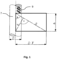
- a "development" of the surface of the strand-like material 7 is considered on a section which has a length corresponding to the distance by which the strand-like material moves around the strand-like material 9 during one revolution of the strand material, ie a rectangular development of the surface of the strand-like material (in Fig. 1 heavily outlined) with height h, width ⁇ ⁇ D and thus area h ⁇ ⁇ D.
- a rectangular surface of a section of the "band" formed by a strand of material 9 with a width S and a height b and thus the area b S is wound onto this rectangular development of the strand-like material.
- the rectangular surface of the strand of material 9 does not lie exactly on the rectangular development of the strand-like material, but the two rectangular surfaces overlap each other. However, these overlaps compensate each other so that the ratio defining the degree of overlap corresponds exactly to the ratio of the areas of the two rectangular surfaces.
- the relationship just mentioned is used to control or regulate the relative feed rate of the strand-like material.
- the measured diameter D, the predetermined degree of coverage k and the constants f, X and d are known, from which the relative feed rate h of the strand-like material can be calculated and used as a target value for the control or regulation of the braiding machine. In this way - apart from errors in the measurement the diameter D and the control or regulation of the relative feed rate h - ensures that the manufactured product has the given degree of coverage k.
- the braiding angle defined above is additionally measured and used to control or regulate the relative feed rate of the strand-like material.
- the control or regulation of the relative feed rate of the strand-like material can be carried out in such a way that a target value for the braiding angle is determined and by changing the relative feed rate while simultaneously measuring the braiding angle, the braiding angle is also changed until it has reached its target value.
- ⁇ denotes the braiding angle.
- the relationship just mentioned is used to control or regulate the relative feed rate of the strand-like material.
- the measured diameter D, the predetermined degree of coverage k and the constants f, X and d are known, from which the braiding angle ⁇ is calculated. and can be used as a target value for the control or regulation of the braiding machine. In this way, apart from errors in the measurement of the diameter D and the control or regulation of the relative feed rate h using the braiding angle ⁇ , it is ensured that the manufactured product has the given degree of coverage k.
- the invention further relates to a braiding, winding or spiraling machine which is designed to be operated according to a method according to the invention for braiding, winding or spiraling a strand-like material, in particular a cable, with at least one strand of material made of at least one strand of material, in particular of at least one wire, and which is designed to repeatedly guide the at least one strand of material around the longitudinal axis of the strand-like material and to simultaneously move the strand-like material essentially in the direction of its longitudinal axis always in the same direction.
- the braiding, winding or spiraling machine has a measuring device for a diameter of a cross section of the strand-like material substantially perpendicular to its longitudinal axis and a control or regulating device for controlling or regulating a relative feed rate of the strand-like material, defined as a distance by which the strand-like material moves during a complete rotation of the at least one strand of material around the longitudinal axis of the strand-like material, depending on this measured diameter such that the degree of coverage of the strand-like material by the at least one strand of material substantially corresponds to a predetermined value.
- the braiding, winding or spiraling machine according to the invention is designed to be operated according to a method according to the invention using the braiding angle to control or regulate the relative feed rate of the strand-like material, and for this purpose further comprises a measuring device for the braiding angle on.
- Fig. 1 has already been explained above.
- Fig. 2 shows the functional principle of a braiding machine 1 according to the invention using a schematic drawing.
- the braiding machine 1 has a number, for example 8, 12 or 16, of upper braiding spools 2, on each of which an upper thread 9 (the so-called weft thread) is wound.
- the upper thread 9 can in particular be a textile thread, a wire or a bundle of several such textile threads or wires.
- the upper braiding spools 2 are mounted on spool carriers (not shown) which rotate separately from one another on gear wheels on a gear ring mounted on a lower spool table 4 (neither shown) and all rotate in the same direction, for example anti-clockwise (indicated by the upper rotating arrow 17).
- the braiding machine 1 has a number, for example also 8, 12 or 16, of lower braiding spools 3, on each of which a lower thread 10 (the so-called warp thread) is wound.
- the number of lower The number of braiding spools 3 is preferably the same as the number of upper braiding spools 2.
- the lower thread 10 is preferably the same thread as the upper thread 9.
- the lower braiding spools 3 are mounted on a common lower spool table 4, which rotates in a direction opposite to the upper braiding spools 2, for example clockwise (indicated by the lower circulating arrow 18).
- the axis around which the upper braiding spools 2 and the lower braiding spools 3 rotate together but in opposite directions coincides with the so-called braiding axis 5.
- a cable 6 - here still unshielded - is introduced into the braiding machine 1 from below along the braiding axis 5 and runs out of the braiding machine 1 again at the upper end.
- the upper threads 9 running from the upper braiding spools 2 and the lower threads 10 running from the lower braiding spools 3 converge at the braiding point 8 on the braiding axis 5 and there braid the unshielded cable 6, which is then pulled off at the upper end of the braiding machine 1 as a shielded cable 7 by a pull-off disk (not shown).
- the lower threads 10 which rotate with the lower braiding spools 3 in the opposite direction to the upper threads 9 with the upper braiding spools 2 around the braiding axis 5, are alternately guided over one or more adjacent upper braiding spools 2 and under one or more adjacent upper braiding spools 2, for example over or under two adjacent upper braiding spools 2.
- Each lower thread 10 dips into vertical slots in an upper inner housing 19 during its up and down movement.
- each lower thread 10 runs over a roller at one end of a braiding lever 11 and is alternately lifted up or pressed down by the braiding lever 11 before passing an "oncoming" upper spool 2 and is thus guided over the upper braiding spool 2 or under the upper braiding spool 2.
- each lower thread 10 is assigned its own braiding lever 11, which can be rotated about a pivot bearing 12, which is attached to a holder 13 connected to the lower spool table 4.
- Each braiding lever 11 can be controlled via a rod 14, the upper end of which is rotatably connected to the braiding lever 11 and the lower end of which runs in a fixed, rotating curved path of a curved control 15.
- the wave shape of the curved path of the curved control 15 leads to an up and down sliding movement of the rod 14 and thus to the desired up and down pivoting movement of the braiding lever 11, which is synchronized with the movement of the upper braiding spools 2.
- the braiding lever 11 can also be guided directly in the curved path of the curved control 15.
- a diameter measuring device 16 is arranged, which measures the diameter of a cross section of the cable 6 essentially perpendicular to the braiding axis 5.
- the diameter measurement is preferably carried out continuously, but can also be carried out periodically with a certain frequency.
- the diameter measurement is carried out using a suitable measuring device, preferably mechanical, for example by two spring-mounted rollers, which are pressed against the cable 6 from the outside on two opposite sides.
- the distance between the two rollers and thus the diameter of the cable 6 can be determined, for example, via the spring tension with which the two rollers are pressed apart, or also by an optical or other measuring displacement sensor.
- the diameter measurement can also be carried out purely optically, for example by means of a laser sensor, or alternatively by means of a camera which continuously films the cable 6 running through it and whose camera images are evaluated.
- the braiding machine 1 can also have a measuring device (not shown) for the braiding angle ⁇ .
- the method according to the invention is preferably stored in the form of control software in a control device of the braiding machine 1.
- the operator of the braiding machine 1 enters a target value for the degree of coverage k into the control.
- the diameter D of the cable 6 can also be entered into the control as a target value. Alternatively, the measured diameter D can also be adopted into the control.
- the values for v Soll,1 and v Soll,2 determined in this way are passed on to the respective control system for the speed of the braiding spools 2, 3 or the take-off speed as setpoint values.
- the respective control system then controls or regulates the Speed or the withdrawal speed to the value v Soll,1 or v Soll,2 . In this way, it is ensured that the braided cable 7 essentially has the specified degree of coverage k.
- a target value ⁇ target for the braiding angle ⁇ can be calculated - preferably using the mathematical relationship given above. Then, for example, with a constant take-off speed of the braided cable 7, the speed of the braiding spools 2, 3 can be changed and the braiding angle ⁇ measured at the same time until the braiding angle ⁇ has assumed the target value ⁇ target . This also ensures that the braided cable 7 essentially has the specified degree of coverage k.
Landscapes
- Engineering & Computer Science (AREA)
- Textile Engineering (AREA)
- Manufacturing & Machinery (AREA)
- Braiding, Manufacturing Of Bobbin-Net Or Lace, And Manufacturing Of Nets By Knotting (AREA)
- Ropes Or Cables (AREA)
Claims (8)
- Procédé d'exploitation d'une machine à tresser, enrouler ou spiraler (1) pour le tressage, l'enroulement ou le spiralage d'un matériau (6) filiforme avec au moins un brin d'écheveau (9, 10) constitué d'au moins une fibre d'écheveau, dans lequel le au moins un brin d'écheveau (9, 10) est fixé en au moins un emplacement contre le matériau (6) filiforme de façon à être bloqué en rotation, le au moins un brin d'écheveau (9, 10) est guidé de façon répétée autour de l'axe longitudinal du matériau (6) filiforme et le matériau (6) filiforme est simultanément déplacé essentiellement dans la direction de son axe longitudinal (5) et toujours dans la même direction, de sorte que le au moins un brin d'écheveau (9, 10) prenne la forme d'une spirale menant autour du matériau (6) filiforme,dans lequel un diamètre (D) d'une section transversale du matériau (6) filiforme est mesuré essentiellement à la perpendiculaire de l'axe longitudinal (5) de celui-ci et une vitesse d'avancement du matériau (6) filiforme et/ou une vitesse de rotation à laquelle le au moins un brin d'écheveau (9, 10) se déplace autour de l'axe longitudinal (5) du matériau (6) filiforme sont commandées ou régulées en fonction de ce diamètre (D) mesuré,caractérisé en ce queune vitesse d'avancement (h) relative du matériau (6) filiforme, définie en tant que distance autour de laquelle le matériau (6) filiforme se déplace lors d'une rotation complète du au moins un brin d'écheveau (9, 10) autour de l'axe longitudinal (5) du matériau (6) filiforme, est commandée ou régulée en fonction du diamètre (D) mesuré de la section transversale du matériau (6) filiforme, de sorte qu'un degré de recouvrement (k) du matériau (6) filiforme par le au moins un brin d'écheveau (9, 10) corresponde essentiellement à une valeur prédéfinie, ledit degré de recouvrement étant défini en tant que rapport entre d'une part la surface totale, radialement orientée vers l'extérieur, de tous les brins d'écheveau (9, 10) qui recouvrent le matériau (6) filiforme dans une section déterminée du matériau (6) filiforme et d'autre part la surface du matériau (6) filiforme dans cette section.
- Procédé d'exploitation d'une machine à tresser, enrouler ou spiraler (1) selon la revendication 1, caractérisé en ce que le matériau (6) filiforme est un câble et/ou en ce que la fibre d'écheveau est un fil.
- Procédé d'exploitation d'une machine à tresser, enrouler ou spiraler (1) selon l'une des revendications précédentes, caractérisé en ce que, pour la commande ou la régulation de la vitesse d'avancement (h) relative du matériau (6) filiforme, est utilisée la relation
 h est la vitesse d'avancement relative du matériau (6) filiforme,D est le diamètre d'une section transversale du matériau (6) filiforme essentiellement à la perpendiculaire de l'axe longitudinal (5) de celui-ci,k est le degré de recouvrement du matériau (6) filiforme par le au moins un brin d'écheveau (9, 10),f est le nombre de fibres d'écheveau dans le au moins un brin d'écheveau (9, 10),d est le diamètre d'une section transversale d'une fibre d'écheveau essentiellement à la perpendiculaire de l'axe longitudinal de celle-ci etX est le nombre des brins d'écheveau (9, 10) pris en compte pour le degré de recouvrement.
 - Procédé d'exploitation d'une machine à tresser, enrouler ou spiraler (1) selon l'une des revendications précédentes, caractérisé en ce qu'un angle de tressage (α) est mesuré et utilisé pour la commande ou la régulation de la vitesse d'avancement (h) relative du matériau (6) filiforme, ledit angle de tressage étant défini en tant qu'angle entre d'une part une demi-droite parallèle à l'axe longitudinal (5) du matériau (6) filiforme et passant à l'opposé de la direction de déplacement du matériau (6) filiforme par le point de dépôt du au moins un brin d'écheveau (9, 10) sur le matériau (6) filiforme et d'autre part le au moins un brin d'écheveau (9, 10) se déposant sur le matériau (6) filiforme.
- Procédé d'exploitation d'une machine à tresser, enrouler ou spiraler (1) selon la revendication 4, caractérisé en ce que, pour la commande ou la régulation de la vitesse d'avancement (h) relative du matériau (6) filiforme et en utilisant l'angle de tressage (α), est utilisée la relation
 α est l'angle de tressage,D est le diamètre d'une section transversale du matériau (6) filiforme essentiellement à la perpendiculaire de l'axe longitudinal (5) de celui-ci,k est le degré de recouvrement du matériau (6) filiforme par le au moins un brin d'écheveau (9, 10),f est le nombre de fibres d'écheveau dans le au moins un brin d'écheveau (9, 10),d est le diamètre d'une section transversale d'une fibre d'écheveau essentiellement à la perpendiculaire de l'axe longitudinal de celle-ci etX est le nombre des brins d'écheveau (9, 10) pris en compte pour le degré de recouvrement.
 - Machine à tresser, enrouler ou spiraler (1) qui est conçue pour être exploitée selon un procédé de tressage, d'enroulement ou de spiralage d'un matériau (6) filiforme avec au moins un brin d'écheveau (9, 10) constitué d'au moins une fibre d'écheveau selon l'une des revendications précédentes, et qui est conçue pour guider de façon répétée le au moins un brin d'écheveau (9, 10) autour de l'axe longitudinal (5) du matériau (6) filiforme et simultanément déplacer le matériau (6) filiforme essentiellement dans la direction de son axe longitudinal (5) et toujours dans la même direction, caractérisée par un dispositif de mesure (16) pour un diamètre (D) d'une section transversale du matériau (6) filiforme essentiellement à la perpendiculaire de l'axe longitudinal (5) de celui-ci et un dispositif de commande ou de régulation pour la commande ou la régulation en fonction de ce diamètre (D) mesuré d'une vitesse d'avancement (h) relative du matériau (6) filiforme, de sorte que le degré de recouvrement (k) du matériau (6) filiforme par le au moins un brin d'écheveau (9, 10) corresponde essentiellement à une valeur prédéfinie, ladite vitesse d'avancement étant définie en tant que distance autour de laquelle le matériau (6) filiforme se déplace lors d'une rotation complète du au moins un brin d'écheveau (9, 10) autour de l'axe longitudinal (5) du matériau (6) filiforme.
- Machine à tresser, enrouler ou spiraler (1) selon la revendication 6, caractérisée en ce que le matériau (6) filiforme est un câble et/ou en ce que la fibre d'écheveau est un fil.
- Machine à tresser, enrouler ou spiraler (1) selon la revendication 6 ou 7, caractérisée par un dispositif de mesure pour l'angle de tressage (α).
Applications Claiming Priority (2)
| Application Number | Priority Date | Filing Date | Title |
|---|---|---|---|
| DE102019211030.4A DE102019211030A1 (de) | 2019-07-25 | 2019-07-25 | Flecht-, Wickel- oder Spiralisiermaschine und Verfahren zu deren Betrieb |
| PCT/EP2020/068771 WO2021013500A1 (fr) | 2019-07-25 | 2020-07-03 | Machine à tresser, à enrouler ou à spiraliser et procédé pour la faire fonctionner |
Publications (2)
| Publication Number | Publication Date |
|---|---|
| EP4004263A1 EP4004263A1 (fr) | 2022-06-01 |
| EP4004263B1 true EP4004263B1 (fr) | 2024-12-11 |
Family
ID=71527785
Family Applications (1)
| Application Number | Title | Priority Date | Filing Date |
|---|---|---|---|
| EP20737414.1A Active EP4004263B1 (fr) | 2019-07-25 | 2020-07-03 | Machine à tresser, à enrouler ou à spiraliser et procédé pour la faire fonctionner |
Country Status (10)
| Country | Link |
|---|---|
| US (1) | US12173450B2 (fr) |
| EP (1) | EP4004263B1 (fr) |
| JP (1) | JP7549646B2 (fr) |
| CN (1) | CN114096704B (fr) |
| DE (1) | DE102019211030A1 (fr) |
| ES (1) | ES3014186T3 (fr) |
| HU (1) | HUE070357T2 (fr) |
| MX (1) | MX2022000983A (fr) |
| PL (1) | PL4004263T3 (fr) |
| WO (1) | WO2021013500A1 (fr) |
Families Citing this family (3)
| Publication number | Priority date | Publication date | Assignee | Title |
|---|---|---|---|---|
| US11674245B2 (en) | 2021-06-22 | 2023-06-13 | Apple Inc. | Braided electronic device cable, braiding machine and method for braiding an electronic device cable |
| CN115772814B (zh) * | 2022-11-30 | 2025-12-16 | 平阳县左右花边机械有限公司 | 一种打绳机 |
| KR102891688B1 (ko) | 2025-07-28 | 2025-11-28 | (주)경흥 | 콘트롤케이블 아우터 케이싱 제조장치 |
Family Cites Families (12)
| Publication number | Priority date | Publication date | Assignee | Title |
|---|---|---|---|---|
| GB143019A (en) * | 1919-05-05 | 1920-05-20 | Boston Machinery Company | Improvements in or relating to braiding machines |
| US3808078A (en) | 1970-01-05 | 1974-04-30 | Norfin | Glass fiber cable, method of making, and its use in the manufacture of track vehicles |
| DE2162170A1 (de) | 1971-12-15 | 1973-06-20 | Spirka Masch Vorrichtungsbau | Schnellflechtmaschine zum umflechten von strangfoermigem gut |
| JPS6266922A (ja) * | 1985-09-18 | 1987-03-26 | Tokai Rubber Ind Ltd | 編組補強長尺体の編組装置及び編組方法 |
| JP2683449B2 (ja) * | 1990-11-10 | 1997-11-26 | 萩原工業株式会社 | 編組装置 |
| JP3278266B2 (ja) * | 1993-11-10 | 2002-04-30 | 萩原工業株式会社 | 編組装置 |
| DE19713706A1 (de) * | 1997-04-03 | 1998-10-08 | Sembritzky Seilerei Gmbh | Drahthohlflechtleine aus Chemiefaserstoff |
| DE19837172C2 (de) * | 1998-08-17 | 2003-10-30 | Wolfgang Emmerich | Vorrichtung zur Steuerung des Fadenhebels einer Flechtmaschine und Flechtmaschine |
| JP2009046206A (ja) * | 2007-08-13 | 2009-03-05 | Fujifilm Corp | ワイヤー巻回方法及びワイヤー巻回機 |
| DE102012112911A1 (de) * | 2012-12-21 | 2014-06-26 | Casar Drahtseilwerk Saar Gmbh | Drahtseil sowie Verfahren und Vorrichtung zur Herstellung des Drahtseils |
| JP6535541B2 (ja) * | 2015-08-04 | 2019-06-26 | 日特エンジニアリング株式会社 | 線材撚り装置及び撚り線の製造方法 |
| CN206477109U (zh) * | 2017-01-24 | 2017-09-08 | 青岛中亿伟业机械制造有限公司 | 一种回转式软管编织机 |
-
2019
- 2019-07-25 DE DE102019211030.4A patent/DE102019211030A1/de active Pending
-
2020
- 2020-07-03 ES ES20737414T patent/ES3014186T3/es active Active
- 2020-07-03 PL PL20737414.1T patent/PL4004263T3/pl unknown
- 2020-07-03 JP JP2022504677A patent/JP7549646B2/ja active Active
- 2020-07-03 WO PCT/EP2020/068771 patent/WO2021013500A1/fr not_active Ceased
- 2020-07-03 US US17/627,492 patent/US12173450B2/en active Active
- 2020-07-03 CN CN202080050522.6A patent/CN114096704B/zh active Active
- 2020-07-03 HU HUE20737414A patent/HUE070357T2/hu unknown
- 2020-07-03 EP EP20737414.1A patent/EP4004263B1/fr active Active
- 2020-07-03 MX MX2022000983A patent/MX2022000983A/es unknown
Also Published As
| Publication number | Publication date |
|---|---|
| WO2021013500A1 (fr) | 2021-01-28 |
| PL4004263T3 (pl) | 2025-04-14 |
| CN114096704B (zh) | 2023-07-28 |
| CN114096704A (zh) | 2022-02-25 |
| JP7549646B2 (ja) | 2024-09-11 |
| JP2022541327A (ja) | 2022-09-22 |
| US20220259801A1 (en) | 2022-08-18 |
| US12173450B2 (en) | 2024-12-24 |
| HUE070357T2 (hu) | 2025-06-28 |
| DE102019211030A1 (de) | 2021-01-28 |
| MX2022000983A (es) | 2022-02-16 |
| EP4004263A1 (fr) | 2022-06-01 |
| ES3014186T3 (en) | 2025-04-21 |
Similar Documents
| Publication | Publication Date | Title |
|---|---|---|
| EP4004263B1 (fr) | Machine à tresser, à enrouler ou à spiraliser et procédé pour la faire fonctionner | |
| CH625459A5 (fr) | ||
| DE2644512A1 (de) | Vorrichtung zur herstellung von drahtbewehrten rohren | |
| EP3325256B1 (fr) | Dispositif et procédé de fabrication d'une barre profilée renforcée par une fibre | |
| EP4127286B1 (fr) | Machine à tresser rotative | |
| EP1136616B1 (fr) | Procédé et dispositif de préformage de fils en acier | |
| DE60111798T2 (de) | Hochgeschwindigkeits-Schneidevorrichtung zum Schneiden von Verstärkungselementen für Luftreifen. | |
| DE2813966C2 (fr) | ||
| DE3824757A1 (de) | Verfahren zur verstaerkung von langgestreckten profilen | |
| DE19535025A1 (de) | Verfahren und Vorrichtung zum gleichzeitigen Bewickeln einer Mehrdrahtspule mit mehreren Drähten und/oder gleichzeitigem Abwickeln der Drähte von einer derart bewickelten Mehrdrahtspule für eine nachfolgende Verseilung derselben | |
| EP3738753B1 (fr) | Procédé et dispositif de fabrication d'un faisceau de fibres hybrides | |
| DE2455154A1 (de) | Geraet zum verarbeiten von faeden | |
| DE102015214076B3 (de) | Vorrichtung und Verfahren zur Fertigung von faserverstärkten Strangprofilen | |
| EP0725852B1 (fr) | Procede et dispositif de production de cable acier | |
| EP0820542B1 (fr) | Installation de fabrication d'au moins une bande de tricot avec insertion de fils elastiques crochetes | |
| DE3004375A1 (de) | Verfahren und vorrichtung zum herstellen von metallschnueren, insbesondere von schnueren zum verstaerken von gegenstaenden aus elastomerem material | |
| DE3206636C2 (fr) | ||
| EP3124661A1 (fr) | Écartement dynamique de faisceaux de fibres continues pendant un processus de fabrication | |
| DE102019117010A1 (de) | Umschlingungsvorrichtung | |
| AT521026B1 (de) | Vorrichtung zur Herstellung einer geflochtenen Ummantelung | |
| DE102005026464B4 (de) | Spiralisiermaschine und Verfahren zur Fadenzuführung bei einer solchen | |
| DE4324973C2 (de) | Verfahren und Vorrichtung zur kontinuierlichen Herstellung von Armierungen von Schläuchen und anderen langgestreckten Hohlkörpern | |
| DE102017205014B4 (de) | Verlitzmaschine, Verfahren zur Herstellung einer Litze und Litze | |
| DE102008011351B4 (de) | Vorrichtung und Verfahren zur automatisierten Reibkraftregelung bei der Oberflächenbehandlung eines Strangs mit Hilfe eines umschlingenden textilen Strangs | |
| DE102016213353A1 (de) | Vorrichtung und Verfahren zur Fertigung eines faserverstärkten Strangprofils |
Legal Events
| Date | Code | Title | Description |
|---|---|---|---|
| STAA | Information on the status of an ep patent application or granted ep patent |
Free format text: STATUS: UNKNOWN |
|
| STAA | Information on the status of an ep patent application or granted ep patent |
Free format text: STATUS: THE INTERNATIONAL PUBLICATION HAS BEEN MADE |
|
| PUAI | Public reference made under article 153(3) epc to a published international application that has entered the european phase |
Free format text: ORIGINAL CODE: 0009012 |
|
| STAA | Information on the status of an ep patent application or granted ep patent |
Free format text: STATUS: REQUEST FOR EXAMINATION WAS MADE |
|
| 17P | Request for examination filed |
Effective date: 20220216 |
|
| AK | Designated contracting states |
Kind code of ref document: A1 Designated state(s): AL AT BE BG CH CY CZ DE DK EE ES FI FR GB GR HR HU IE IS IT LI LT LU LV MC MK MT NL NO PL PT RO RS SE SI SK SM TR |
|
| DAV | Request for validation of the european patent (deleted) | ||
| DAX | Request for extension of the european patent (deleted) | ||
| GRAP | Despatch of communication of intention to grant a patent |
Free format text: ORIGINAL CODE: EPIDOSNIGR1 |
|
| STAA | Information on the status of an ep patent application or granted ep patent |
Free format text: STATUS: GRANT OF PATENT IS INTENDED |
|
| RIC1 | Information provided on ipc code assigned before grant |
Ipc: D07B 7/14 20060101ALI20240731BHEP Ipc: D07B 7/02 20060101ALI20240731BHEP Ipc: D04C 3/42 20060101ALI20240731BHEP Ipc: D04C 1/12 20060101AFI20240731BHEP |
|
| RIC1 | Information provided on ipc code assigned before grant |
Ipc: D07B 7/02 20060101ALI20240802BHEP Ipc: D07B 7/14 20060101ALI20240802BHEP Ipc: D04C 3/48 20060101ALI20240802BHEP Ipc: D04C 3/42 20060101ALI20240802BHEP Ipc: D04C 1/12 20060101AFI20240802BHEP |
|
| INTG | Intention to grant announced |
Effective date: 20240816 |
|
| GRAS | Grant fee paid |
Free format text: ORIGINAL CODE: EPIDOSNIGR3 |
|
| GRAA | (expected) grant |
Free format text: ORIGINAL CODE: 0009210 |
|
| STAA | Information on the status of an ep patent application or granted ep patent |
Free format text: STATUS: THE PATENT HAS BEEN GRANTED |
|
| P01 | Opt-out of the competence of the unified patent court (upc) registered |
Free format text: CASE NUMBER: UPC_APP_118899/2023 Effective date: 20230510 |
|
| AK | Designated contracting states |
Kind code of ref document: B1 Designated state(s): AL AT BE BG CH CY CZ DE DK EE ES FI FR GB GR HR HU IE IS IT LI LT LU LV MC MK MT NL NO PL PT RO RS SE SI SK SM TR |
|
| REG | Reference to a national code |
Ref country code: GB Ref legal event code: FG4D Free format text: NOT ENGLISH |
|
| REG | Reference to a national code |
Ref country code: CH Ref legal event code: EP |
|
| REG | Reference to a national code |
Ref country code: DE Ref legal event code: R096 Ref document number: 502020009949 Country of ref document: DE |
|
| REG | Reference to a national code |
Ref country code: IE Ref legal event code: FG4D Free format text: LANGUAGE OF EP DOCUMENT: GERMAN |
|
| REG | Reference to a national code |
Ref country code: LT Ref legal event code: MG9D |
|
| PG25 | Lapsed in a contracting state [announced via postgrant information from national office to epo] |
Ref country code: HR Free format text: LAPSE BECAUSE OF FAILURE TO SUBMIT A TRANSLATION OF THE DESCRIPTION OR TO PAY THE FEE WITHIN THE PRESCRIBED TIME-LIMIT Effective date: 20241211 |
|
| PG25 | Lapsed in a contracting state [announced via postgrant information from national office to epo] |
Ref country code: FI Free format text: LAPSE BECAUSE OF FAILURE TO SUBMIT A TRANSLATION OF THE DESCRIPTION OR TO PAY THE FEE WITHIN THE PRESCRIBED TIME-LIMIT Effective date: 20241211 |
|
| PG25 | Lapsed in a contracting state [announced via postgrant information from national office to epo] |
Ref country code: BG Free format text: LAPSE BECAUSE OF FAILURE TO SUBMIT A TRANSLATION OF THE DESCRIPTION OR TO PAY THE FEE WITHIN THE PRESCRIBED TIME-LIMIT Effective date: 20241211 |
|
| REG | Reference to a national code |
Ref country code: NL Ref legal event code: MP Effective date: 20241211 |
|
| REG | Reference to a national code |
Ref country code: ES Ref legal event code: FG2A Ref document number: 3014186 Country of ref document: ES Kind code of ref document: T3 Effective date: 20250421 |
|
| PG25 | Lapsed in a contracting state [announced via postgrant information from national office to epo] |
Ref country code: NO Free format text: LAPSE BECAUSE OF FAILURE TO SUBMIT A TRANSLATION OF THE DESCRIPTION OR TO PAY THE FEE WITHIN THE PRESCRIBED TIME-LIMIT Effective date: 20250311 |
|
| PG25 | Lapsed in a contracting state [announced via postgrant information from national office to epo] |
Ref country code: LV Free format text: LAPSE BECAUSE OF FAILURE TO SUBMIT A TRANSLATION OF THE DESCRIPTION OR TO PAY THE FEE WITHIN THE PRESCRIBED TIME-LIMIT Effective date: 20241211 Ref country code: GR Free format text: LAPSE BECAUSE OF FAILURE TO SUBMIT A TRANSLATION OF THE DESCRIPTION OR TO PAY THE FEE WITHIN THE PRESCRIBED TIME-LIMIT Effective date: 20250312 |
|
| PG25 | Lapsed in a contracting state [announced via postgrant information from national office to epo] |
Ref country code: RS Free format text: LAPSE BECAUSE OF FAILURE TO SUBMIT A TRANSLATION OF THE DESCRIPTION OR TO PAY THE FEE WITHIN THE PRESCRIBED TIME-LIMIT Effective date: 20250311 |
|
| PG25 | Lapsed in a contracting state [announced via postgrant information from national office to epo] |
Ref country code: NL Free format text: LAPSE BECAUSE OF FAILURE TO SUBMIT A TRANSLATION OF THE DESCRIPTION OR TO PAY THE FEE WITHIN THE PRESCRIBED TIME-LIMIT Effective date: 20241211 |
|
| REG | Reference to a national code |
Ref country code: HU Ref legal event code: AG4A Ref document number: E070357 Country of ref document: HU |
|
| PG25 | Lapsed in a contracting state [announced via postgrant information from national office to epo] |
Ref country code: SM Free format text: LAPSE BECAUSE OF FAILURE TO SUBMIT A TRANSLATION OF THE DESCRIPTION OR TO PAY THE FEE WITHIN THE PRESCRIBED TIME-LIMIT Effective date: 20241211 |
|
| PGFP | Annual fee paid to national office [announced via postgrant information from national office to epo] |
Ref country code: PL Payment date: 20250619 Year of fee payment: 6 |
|
| PG25 | Lapsed in a contracting state [announced via postgrant information from national office to epo] |
Ref country code: IS Free format text: LAPSE BECAUSE OF FAILURE TO SUBMIT A TRANSLATION OF THE DESCRIPTION OR TO PAY THE FEE WITHIN THE PRESCRIBED TIME-LIMIT Effective date: 20250411 |
|
| PG25 | Lapsed in a contracting state [announced via postgrant information from national office to epo] |
Ref country code: PT Free format text: LAPSE BECAUSE OF FAILURE TO SUBMIT A TRANSLATION OF THE DESCRIPTION OR TO PAY THE FEE WITHIN THE PRESCRIBED TIME-LIMIT Effective date: 20250411 |
|
| PG25 | Lapsed in a contracting state [announced via postgrant information from national office to epo] |
Ref country code: EE Free format text: LAPSE BECAUSE OF FAILURE TO SUBMIT A TRANSLATION OF THE DESCRIPTION OR TO PAY THE FEE WITHIN THE PRESCRIBED TIME-LIMIT Effective date: 20241211 |
|
| PGFP | Annual fee paid to national office [announced via postgrant information from national office to epo] |
Ref country code: RO Payment date: 20250626 Year of fee payment: 6 |
|
| PG25 | Lapsed in a contracting state [announced via postgrant information from national office to epo] |
Ref country code: SK Free format text: LAPSE BECAUSE OF FAILURE TO SUBMIT A TRANSLATION OF THE DESCRIPTION OR TO PAY THE FEE WITHIN THE PRESCRIBED TIME-LIMIT Effective date: 20241211 |
|
| PGFP | Annual fee paid to national office [announced via postgrant information from national office to epo] |
Ref country code: TR Payment date: 20250630 Year of fee payment: 6 |
|
| PGFP | Annual fee paid to national office [announced via postgrant information from national office to epo] |
Ref country code: CZ Payment date: 20250619 Year of fee payment: 6 |
|
| PGFP | Annual fee paid to national office [announced via postgrant information from national office to epo] |
Ref country code: HU Payment date: 20250626 Year of fee payment: 6 |
|
| PG25 | Lapsed in a contracting state [announced via postgrant information from national office to epo] |
Ref country code: SE Free format text: LAPSE BECAUSE OF FAILURE TO SUBMIT A TRANSLATION OF THE DESCRIPTION OR TO PAY THE FEE WITHIN THE PRESCRIBED TIME-LIMIT Effective date: 20241211 |
|
| REG | Reference to a national code |
Ref country code: DE Ref legal event code: R097 Ref document number: 502020009949 Country of ref document: DE |
|
| PGFP | Annual fee paid to national office [announced via postgrant information from national office to epo] |
Ref country code: ES Payment date: 20250819 Year of fee payment: 6 |
|
| PG25 | Lapsed in a contracting state [announced via postgrant information from national office to epo] |
Ref country code: DK Free format text: LAPSE BECAUSE OF FAILURE TO SUBMIT A TRANSLATION OF THE DESCRIPTION OR TO PAY THE FEE WITHIN THE PRESCRIBED TIME-LIMIT Effective date: 20241211 |
|
| PGFP | Annual fee paid to national office [announced via postgrant information from national office to epo] |
Ref country code: DE Payment date: 20250722 Year of fee payment: 6 |
|
| PGFP | Annual fee paid to national office [announced via postgrant information from national office to epo] |
Ref country code: IT Payment date: 20250731 Year of fee payment: 6 |
|
| PLBE | No opposition filed within time limit |
Free format text: ORIGINAL CODE: 0009261 |
|
| STAA | Information on the status of an ep patent application or granted ep patent |
Free format text: STATUS: NO OPPOSITION FILED WITHIN TIME LIMIT |
|
| PGFP | Annual fee paid to national office [announced via postgrant information from national office to epo] |
Ref country code: FR Payment date: 20250723 Year of fee payment: 6 Ref country code: AT Payment date: 20250721 Year of fee payment: 6 |
|
| PGFP | Annual fee paid to national office [announced via postgrant information from national office to epo] |
Ref country code: CH Payment date: 20250801 Year of fee payment: 6 |
|
| 26N | No opposition filed |
Effective date: 20250912 |
|
| PG25 | Lapsed in a contracting state [announced via postgrant information from national office to epo] |
Ref country code: LU Free format text: LAPSE BECAUSE OF NON-PAYMENT OF DUE FEES Effective date: 20250703 |
|
| GBPC | Gb: european patent ceased through non-payment of renewal fee |
Effective date: 20250703 |
|
| REG | Reference to a national code |
Ref country code: BE Ref legal event code: MM Effective date: 20250731 |
|
| PG25 | Lapsed in a contracting state [announced via postgrant information from national office to epo] |
Ref country code: GB Free format text: LAPSE BECAUSE OF NON-PAYMENT OF DUE FEES Effective date: 20250703 |
|
| PG25 | Lapsed in a contracting state [announced via postgrant information from national office to epo] |
Ref country code: BE Free format text: LAPSE BECAUSE OF NON-PAYMENT OF DUE FEES Effective date: 20250731 |