EP4004305B1 - Ensemble de montage pour fixer un échafaudage à une structure - Google Patents
Ensemble de montage pour fixer un échafaudage à une structure Download PDFInfo
- Publication number
- EP4004305B1 EP4004305B1 EP20737112.1A EP20737112A EP4004305B1 EP 4004305 B1 EP4004305 B1 EP 4004305B1 EP 20737112 A EP20737112 A EP 20737112A EP 4004305 B1 EP4004305 B1 EP 4004305B1
- Authority
- EP
- European Patent Office
- Prior art keywords
- coupling
- openings
- coupling member
- member reach
- group
- Prior art date
- Legal status (The legal status is an assumption and is not a legal conclusion. Google has not performed a legal analysis and makes no representation as to the accuracy of the status listed.)
- Active
Links
Images

Classifications
-
- E—FIXED CONSTRUCTIONS
- E04—BUILDING
- E04G—SCAFFOLDING; FORMS; SHUTTERING; BUILDING IMPLEMENTS OR AIDS, OR THEIR USE; HANDLING BUILDING MATERIALS ON THE SITE; REPAIRING, BREAKING-UP OR OTHER WORK ON EXISTING BUILDINGS
- E04G5/00—Component parts or accessories for scaffolds
- E04G5/04—Means for fastening, supporting, or bracing scaffolds on or against building constructions
- E04G5/046—Means for fastening, supporting, or bracing scaffolds on or against building constructions for fastening scaffoldings on walls
-
- E—FIXED CONSTRUCTIONS
- E04—BUILDING
- E04G—SCAFFOLDING; FORMS; SHUTTERING; BUILDING IMPLEMENTS OR AIDS, OR THEIR USE; HANDLING BUILDING MATERIALS ON THE SITE; REPAIRING, BREAKING-UP OR OTHER WORK ON EXISTING BUILDINGS
- E04G3/00—Scaffolds essentially supported by building constructions, e.g. adjustable in height
- E04G3/20—Scaffolds essentially supported by building constructions, e.g. adjustable in height supported by walls
-
- E—FIXED CONSTRUCTIONS
- E04—BUILDING
- E04G—SCAFFOLDING; FORMS; SHUTTERING; BUILDING IMPLEMENTS OR AIDS, OR THEIR USE; HANDLING BUILDING MATERIALS ON THE SITE; REPAIRING, BREAKING-UP OR OTHER WORK ON EXISTING BUILDINGS
- E04G5/00—Component parts or accessories for scaffolds
- E04G5/06—Consoles; Brackets
- E04G5/062—Consoles; Brackets specially adapted for attachment to building walls
Definitions
- the present invention relates to an assembly for fixing a scaffold to a building according to the preamble of claim 1.
- Scaffolding can also be constructed in such a way that it is not supported on the ground and runs along the structure, but rather is erected upwards, starting at a certain distance from the ground and fixed to the structure.
- An assembly according to the preamble of claim 1 is known from JP 2019 044394 A
- a first group of coupling element through-openings with two coupling element through-openings arranged at a distance from one another is provided in each of the two first coupling walls of the structural support.
- a second group of coupling element through-openings with two coupling element through-openings is provided, the mutual spacing of which corresponds to the mutual spacing of the coupling element through-openings of each first group of coupling element through-openings in the first coupling walls of the structural support.
- the structural support and the coupling element can be coupled essentially rigidly to one another by two bolt-like coupling elements passed through respective mutually aligned coupling element through-openings of the first groups and the second groups. If only a single bolt-like coupling element is passed through such mutually associated groups, the structural support and the coupling element can be arranged in positions pivoted relative to each other.
- an assembly assembly for fixing a scaffold to a building structure comprising a first assembly unit with a building support to be fixed to a building structure, a scaffold support to be fixed to a scaffold and a coupling element to be coupled to the building support and the scaffold support.
- the first assembly unit thus comprises three essential system areas.
- this is the structural support, which can be constructed and dimensioned in such a way that it can be securely anchored to a structure using conventional fastening elements, such as screw bolts or the like.
- the scaffold support serves to provide a coupling to the scaffolding to be fixed relative to the structure and can thus be optimized with regard to the technical design required for this coupling, for example, adapted to the design of the scaffolding to be erected.
- a connection between the scaffold support and the structural support is provided by the coupling element, which can provide a stable, and in particular also variable, coupling both with regard to the scaffold support and with regard to the structural support.
- the building support comprises a first fastening area to be fixed to a building and a coupling area to be coupled to the coupling element.
- the first fastening area can be plate-shaped and have a plurality of fastening element through-openings.
- the coupling area comprises two of the first fastening area, essentially parallel and spaced apart from each other. protruding first coupling walls, wherein in each first coupling wall at least one first group of coupling element through-openings with at least two coupling element through-openings is provided, wherein each coupling element through-opening of a first group of coupling element through-openings in one of the first coupling walls is opposite a coupling element through-opening of a first group of coupling element through-openings in the other first coupling wall.
- the coupling element For coupling to both the building support and the scaffold support, the coupling element comprises two second coupling walls arranged substantially parallel and spaced apart from one another, wherein at least one second group of coupling element through-openings with at least two coupling element through-openings is provided in each second coupling wall, wherein each coupling element through-opening of a second group of coupling element through-openings in one of the second coupling walls is opposite a coupling element through-opening of a second group of coupling element through-openings in the other second coupling wall.
- At least two second groups of coupling element through-openings arranged at a distance from one another in a direction of variation are provided in every second coupling wall.
- an arrangement pattern of the coupling element through-openings of each first group of coupling element through-openings corresponds to an arrangement pattern of the coupling element through-openings of each second group of coupling element through-openings.
- the two second coupling walls have a smaller mutual distance than the two first coupling walls, wherein the coupling element can be positioned between the two first coupling walls in such a way that coupling element through-openings of a first group of coupling element through-openings in each first coupling wall are aligned with coupling element through-openings of a second group of coupling element through-openings in the respectively immediately adjacent second coupling wall for receiving a coupling element.
- At least one third group of coupling member through-openings with at least two coupling member through-openings can be provided in each second coupling wall, wherein each coupling member through-opening of a third group of coupling member through-openings in one of the second coupling walls is opposite a coupling member through-opening of a third group of coupling member through-openings in the other second coupling wall.
- a stable construction of the coupling element which ensures both a stable connection to the building support and a stable connection to the scaffold support, can be achieved in that the second coupling walls are connected to one another by at least one connecting wall connected to the second coupling walls between the second groups of coupling element through-openings and the third groups of coupling element through-openings.
- the framework support can comprise two third coupling walls arranged substantially parallel and spaced apart from one another, wherein in each third coupling wall at least one fourth group of coupling element through-openings with at least two coupling element through-openings is provided, wherein each coupling element through-opening of a fourth group of coupling element through-openings in one of the third coupling walls is opposite a coupling element through-opening of a fourth group of coupling element through-openings in the other third coupling wall.
- mutual engagement can be achieved in that the two third coupling walls have a smaller mutual distance than the two second coupling walls, wherein the framework support can be positioned between the two second coupling walls in such a way that coupling element through-openings of a third group of coupling element through-openings in each second coupling wall are aligned with coupling element through-openings of a fourth group of coupling element through-openings in the immediately adjacent third coupling wall for receiving a coupling element.
- Each third group of coupling member through-openings may comprise two coupling member through-openings arranged at a first distance from one another, and each fourth group of coupling member through-openings may comprise more than two coupling member through-openings arranged at a second distance from one another, wherein the first distance is twice the second distance. In this way, it is possible to couple the scaffold support to the coupling element in various positions.
- At least one, preferably at least two scaffold coupling units arranged at a distance from one another are provided on the scaffold support.
- each scaffold coupling unit comprises a wedge head connection unit for connection to a perforated disc provided on a scaffold element.
- the second assembly unit comprises a second fastening area to be fixed to a structure and a scaffold coupling unit firmly connected to the second fastening area.
- the scaffold coupling unit can also be designed as a wedge-head connection unit for connection to a perforated disc provided on a scaffold element.
- the present invention further relates to a scaffolding structure comprising at least one scaffolding element secured to a structure by means of an assembly assembly constructed according to the invention.
- a scaffolding element can be designed, for example, as a vertical post.
- a further vertical post can be coupled to the vertical post by at least two horizontal bars and at least two diagonal bars, each horizontal bar and/or each Diagonal bar is connected in both its end areas to one of the vertical posts by a scaffold coupling unit.
- each scaffolding coupling unit comprises a wedge head connection unit coupled to a perforated disc on one of the vertical posts at one end of the horizontal ledgers and/or the diagonal ledgers.
- a diagonal lead is coupled to the other vertical post to the same perforated plate as the horizontal lead, and to a different perforated plate on the vertical post than the horizontal lead.
- a perforated plate located below the perforated plate used to connect the horizontal lead to the vertical post can be used for downward support to connect each diagonal lead to the vertical post.
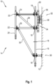
- the Fig. 1 shows a side view of a scaffold, generally designated 10, in particular a construction scaffold.
- Fig. 1 The part of the scaffold 10 shown forms a bracket 14 fixed to a structure 12, on which at a distance from a Fig. 1
- the scaffold 10 can be erected starting from the ground (not shown) and moving upwards along the structure 12.
- the structure 12 can be, for example, the wall of a building or the like.
- the bracket 14 shown is constructed from several individual parts.
- the bracket 14 comprises a vertical post 16 positioned closer to the structure 12 and having a plurality of perforated discs 18 provided thereon at a distance from one another.
- the bracket 14 further comprises another, somewhat shorter vertical post 20, which is positioned at a greater distance from the structure 12 and likewise comprises a plurality of perforated discs 22 provided thereon at a distance.
- the two vertical posts 16, 20 are connected to one another by horizontal bars 24, 26 and diagonal bars 28, 30.
- the diagonal bars 28, 30 ensure that the vertical post 20, which is coupled to the vertical post 16 by means of the horizontal bars 24, 26, is in the Fig. 1 shown, defined height positioning with respect to the vertical post 16.
- Each of the horizontal bars 24, 26 and in this case the diagonal bars 28, 30 is connected to the vertical posts 16, 20 by wedge-head connecting units provided at the ends of these bars, each with a head encompassing a respective perforated disc and a wedge to be passed through a hole in the perforated disc.
- brackets 14 can be fixed horizontally one after the other to the building 12, so that the further part of the scaffold can follow upwards on these brackets.
- An assembly assembly is provided on the bracket 14 of the scaffold 10 shown.
- This assembly assembly 32 comprises a first assembly unit 34 connected to the upper region of the bracket 14 and a second assembly unit 36 connected to the lower region of the bracket 24 or to the vertical post 16.
- the two assembly units 34, 36 ensure a stable anchoring of the bracket 14, and thus of the scaffold 10 built on it, to the structure 12 at a vertical distance.
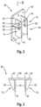
- the first assembly unit 34 comprises a structural support 38 to be secured to the structure 12.
- the structural support 38 is constructed with a plate-like first fastening region 40, in which a plurality of fastening element through-openings 42 are provided.
- Fastening elements for example, designed as screw bolts, can be inserted through the fastening element through-openings 42 into dowels or the like provided in the structure 12.
- First coupling walls 44, 46 which are arranged parallel to one another and approximately orthogonally to the plate-like first fastening region 40, protrude from the plate-like first fastening region 40 and provide a coupling region 48 of the structural support 38.
- the essentially plate-like first coupling walls 44, 46 can have respective fastening projections which can be positioned to engage in openings provided in the plate-like first fastening region 40 for connection thereto.
- the fixed connection can be supported by a material connection, in particular welding.
- a support element 50, 52 is provided in association with each first coupling wall 44, 46, which supports the latter with respect to the plate-like first fastening region 40.
- the support elements 50, 52 can also have projections engaging in corresponding recesses in the first fastening region 40 and the first coupling walls 44, 46 and can be connected to the first fastening region 40 and the Coupling walls 44, 46 can be connected by material closure, in particular welding, to increase stability.
- a first group G 1 of coupling member through-openings is provided in each first coupling wall 44, 46.
- Each first group G 1 comprises two coupling member through-openings 54, 56, which are arranged in a longitudinal direction of the first coupling walls 44, 46, which are Fig. 4 shown variation direction V, are arranged at a distance from one another.
- the support elements 50, 52 are mounted such that they are connected to the first coupling walls 44, 46 between the two coupling member through-openings 54, 56 of a respective first group G 1 .
- the structural support 38 with its plate-like fastening area 40, the two first coupling walls 44, 46 and the support elements 50, 52, can be manufactured entirely from comparatively inexpensive but also stable sheet metal material.
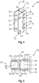
- the Figs. 4 and 5 show a coupling element 58 of the first assembly unit 34, by which the building support 38 is coupled to a scaffold support 60, which will be described in more detail below.
- the coupling element 58 comprises two second coupling walls 62, 64 arranged at a distance from one another and substantially parallel to one another.
- the two second coupling walls 62, 64 are connected to one another by a connecting wall 66 arranged substantially orthogonally thereto.
- This connecting wall 66 can also have projections engaging in corresponding recesses in the second coupling walls 62, 64 or can be fixed to the two second coupling walls 62, 64 by a material connection, such as welding.
- the two second coupling walls 62, 64 are positioned at a smaller distance from each other than the two first coupling walls 44, 46 of the structural support 38.
- the coupling element 58 with its two second coupling walls 62, 64 can be positioned between the two first coupling walls 44, 46 of the structural support 38.
- the distance between the two first coupling walls 44, 46 is such that the two second coupling walls 62, 64 can be positioned without significant lateral play and thus close to a respective first coupling wall 44, 46.
- each second coupling wall 62, 64 two second groups G 2 of coupling element through-openings are provided, one after the other in the direction of variation V.
- Each second group G 2 comprises two coupling element through-openings 68, 70 arranged at a distance in the direction of variation.
- the second groups G 2 of coupling element through-openings in the two second coupling walls 62, 64 are also arranged such that each coupling element through-opening 68, 70 in one of the two second coupling walls 62, 64 is opposite a coupling element through-opening in the other of the two second coupling walls 62, 64.
- a pair of coupling member through-openings 68, 68 and 70, 70 are formed, through which a coupling member, such as a coupling bolt or the like, can be passed due to the existing alignment.
- the arrangement pattern, in particular the mutual spacing, of the respective coupling element through-openings 68, 70 is provided in the same way as the arrangement pattern is provided in the first groups G 1 of coupling element through-openings in the first coupling walls 44, 46.
- the coupling element 58 can be positioned between the two first coupling walls 44, 46 of the structural support 38 such that, for example, Fig. 4 second groups G 2 of coupling member through-openings shown above are aligned with the first groups G 1 of coupling member through-openings provided in the two first coupling walls 44, 46 and each have a Fig.
- coupling member 72 can be guided through the coupling member passage openings 54, 68, 68, 54 and 56, 70, 70, 56 aligned with each other.
- first coupling walls 44, 46 Since only a single first group G 1 of coupling member access openings is provided, it is thus possible to couple the coupling element 58 to the building support 38 in two mutually different height positions.
- Third groups G3 of coupling element through-openings are provided on the two second coupling walls 62, 64, transversely to the variation direction V and spaced from the coupling element through-openings 68, 70 of the second groups G2 .
- Each third group G3 comprises two coupling element through-openings 74, 76 spaced apart in the variation direction V.
- the connecting wall 66 connecting the two second coupling walls 62, 64 is positioned between the coupling element through-openings 74, 76 of the third groups G3 and the coupling element through-openings 68, 70 of the second groups G2 .
- the connecting wall 66 can also be constructed with a plurality of segments spaced apart from one another, for example, in the variation direction V.
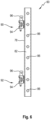
- the Fig. 5 in plan view and in Fig. 6
- the scaffold support 60 which can be seen in the side view, is constructed with a square tube 78.
- the square tube 78 represents Fig. 5 recognizable third coupling walls 80, 82 are provided, which are arranged at a distance from and substantially parallel to one another.
- the mutual spacing of the third coupling walls 80, 82 is dimensioned such that they can be accommodated with little play between the two second coupling walls 62, 64 of the coupling element 58.
- coupling element through-openings 84, 86 are provided in pairs opposite one another. Such pairs are arranged in the longitudinal direction of the square tube or the variation direction V at a distance from one another that corresponds approximately to half the mutual distance between the coupling element through-openings 74, 76 of a respective third group G 3 in the two second coupling walls 62, 64. All consecutive coupling element through-openings 84 in the third coupling wall 80 form a fourth group of coupling element through-openings, while all coupling element through-openings 86 provided in the third coupling wall 82 also form a fourth group of coupling element through-openings G 4 .
- a fastening element 88 for example fastening bolts, can be passed through each of the coupling element through-openings 74, 84, 86, 74 and 76, 84, 86, 76 aligned in this way to achieve a stable coupling of the scaffold support 60 to the coupling element 58.
- the fastening elements 88 can be secured against falling out by means of locking pins, nuts or the like.
- the two fourth groups G 4 of coupling element through-openings have a larger number of coupling element through-openings 84 and 86, respectively, than is the case with the two third groups G 3 of coupling element through-openings, it is possible to arrange the framework support 60 in a variety of different positions with respect to the coupling element 58 and to couple it thereto. This variability in The coupling is superimposed on the variability already present in the area of the coupling of the coupling element 58 with the structure support 38.
- Two scaffold coupling units 90, 92 are provided at a distance from one another on the scaffold support 60.
- Each of the scaffold coupling units 90, 92 can be designed as a wedge-head connection unit, the head 94 of which is secured, for example, by welding to the square tube 78.
- a wedge 96 provided on the respective head 94 can be arranged to penetrate a hole in a perforated disc 18 of the vertical post 16, thus ensuring a stable coupling of the vertical support 16 in the area of each scaffold coupling unit 90 or 92.
- the mutual spacing of the two scaffold coupling units 90, 92 provided on the scaffold support 60 in the variation direction V which therefore essentially also corresponds to the vertical direction or the erection direction of the scaffold 10, is adapted to the mutual spacing between two perforated discs 18 on the vertical post 16.
- the second assembly unit 36 shown comprises a second fastening region 98 which is also essentially plate-shaped.
- a plurality of fastening element through-openings 100 are also provided in this region, through which fastening elements for securing the second assembly unit 36 to the structure 12 can be introduced.
- a scaffold coupling unit 104 for example again designed as a wedge-head connecting unit, is fixed to the second fastening region 98 by a shaft region 102, which can be tubular and can be fixed to the second fastening region 98, for example by welding.
- the length of the second assembly unit 36 between a building support surface 106 and the scaffold coupling unit 104 essentially corresponds to the length between a building support surface 108 of the building girder 38 and the scaffold coupling units 90, 92 provided on the scaffold girder 60, so that when a further perforated disc 18 of the vertical post 16 is coupled to the second assembly unit 36 fixed to the building 12, the vertical post 16 will assume a generally vertical orientation that is essentially parallel to the building 12.
- the inventive construction of an assembly unit makes it possible to flexibly attach scaffolding to a building.
- the scaffolding in particular a bracket provided in the area of attachment to the building 12, can be assembled from standard scaffolding components. Coupling via the assembly unit occurs only in the area of one of the scaffolding components, namely a vertical post 16, to which other scaffolding components, such as the aforementioned crossbeams and diagonal beams, can then be connected.
- This also makes it easy to attach scaffolding or brackets of different widths to a building using one and the same type of assembly unit. The different widths can then be provided simply by selecting, for example, the crossbeams and diagonal beams.
- first assembly unit variations can, of course, also be made in the area of the structural components of the first assembly unit.
- first assembly unit several, for example, two first groups of coupling element access openings could be provided one above the other on the structural support in its first two coupling walls, thus allowing for increased structural variability here as well.
- More than one third group of coupling element access openings could also be provided in the second two coupling walls, for example, in order to achieve even greater variability in this regard.
Landscapes
- Engineering & Computer Science (AREA)
- Architecture (AREA)
- Mechanical Engineering (AREA)
- Civil Engineering (AREA)
- Structural Engineering (AREA)
- Mutual Connection Of Rods And Tubes (AREA)
- Movable Scaffolding (AREA)
Claims (13)
- Ensemble de montage pour la fixation d'un échafaudage sur une construction, comprenant une première unité d'ensemble (34) avec un support de construction (38) à fixer sur une construction (12), un support d'échafaudage (60) à fixer sur un échafaudage (10) et un élément de couplage (58) à coupler avec le support de construction (38) et le support d'échafaudage (60), le support de construction (38) comprenant une première zone de fixation (40) à fixer sur une construction (12) et une zone de couplage (48) à coupler avec l'élément de couplage (58), la zone de couplage (48) comprenant deux premières parois de couplage (44, 46) dépassant de la première zone de fixation (40) sensiblement parallèlement et à distance l'une de l'autre, au moins un premier groupe (G1) d'ouvertures de passage de membre de couplage avec au moins deux ouvertures de passage de membre de couplage (54, 56) étant prévu dans chaque première paroi de couplage (44, 46), chaque ouverture de passage de membre de couplage (54, 56) d'un premier groupe (G1) d'ouvertures de passage de membre de couplage étant prévue dans l'une des premières parois de couplage (44, 46) est opposée à une ouverture de passage de membre de couplage (54, 56) d'un premier groupe (G1) d'ouvertures de passage de membre de couplage dans l'autre première paroi de couplage (44, 46), l'élément de couplage (58) comprenant deux deuxièmes parois de couplage (62, 64) disposées sensiblement parallèlement et à distance l'une de l'autre, au moins un deuxième groupe (G2) d'ouvertures de passage de membre de couplage avec au moins deux ouvertures de passage de membre de couplage (68, 70) étant prévu dans chaque deuxième paroi de couplage (62, 64), chaque ouverture de passage de membre de couplage (68, 70) d'un deuxième groupe (G2) d'ouvertures de passage de membre de couplage dans l'une des deuxièmes parois de couplage (62, 64) étant opposée à une ouverture de passage de membre de couplage (68, 70) d'un deuxième groupe (G2) d'ouvertures de passage de membre de couplage dans l'autre deuxième paroi de couplage (62, 64), caractérisé en ce que dans chaque deuxième paroi de couplage (62, 64) sont prévus au moins deux deuxièmes groupes (G2) d'ouvertures de passage de membre de couplage disposés à distance les uns des autres dans une direction de variation (V).
- Ensemble de montage selon la revendication 1,
caractérisé en ce que la première zone de fixation (40) est réalisée en forme de plaque et présente une pluralité d'ouvertures de passage de membre de fixation (42). - Ensemble de montage selon la revendication 1 ou 2,
caractérisé en ce qu'un motif d'agencement des ouvertures de passage de membre de couplage (54, 56) de chaque premier groupe (G1) d'ouvertures de passage de membre de couplage correspond à un motif d'agencement des ouvertures de passage de membre de couplage (68, 70) de chaque deuxième groupe (G2) d'ouvertures de passage de membre de couplage. - Ensemble de montage selon la revendication 3,
caractérisé en ce que les deux deuxièmes parois de couplage (62, 64) présentent une distance mutuelle plus faible que les deux premières parois de couplage (44, 46), l'élément de couplage (58) pouvant être positionné entre les deux premières parois de couplage (44, 46) de telle sorte que des ouvertures de passage de membre de couplage (54, 56) d'un premier groupe (G1) d'ouvertures de passage de membres de couplage dans chaque première paroi de couplage (44, 46) sont alignées avec des ouvertures de passage de membres de couplage (68, 70) d'un deuxième groupe (G2) d'ouvertures de passage de membres de couplage dans la deuxième paroi de couplage (62, 64) respectivement immédiatement adjacente pour recevoir un membre de couplage (72). - Ensemble de montage selon l'une quelconque des revendications 1 à 4, caractérisé en ce qu'il est prévu dans chaque deuxième paroi de couplage (62, 64) au moins un troisième groupe (G3) d'ouvertures de passage de membre de couplage avec au moins deux ouvertures de passage de membre de couplage (74, 76), chaque ouverture de passage de membre de couplage (74, 76) d'un troisième groupe (G3) d'ouvertures de passage de membres de couplage dans l'une des deuxièmes parois de couplage (62, 64) est opposée à une ouverture de passage de membres de couplage (74, 76) d'un troisième groupe (G3) d'ouvertures de passage de membres de couplage dans l'autre deuxième paroi de couplage (62, 64).
- Ensemble de montage selon la revendication 5,
caractérisé en ce que les deuxièmes parois de couplage (62, 64) sont reliées entre elles par au moins une paroi de liaison (66) reliée aux deuxièmes parois de couplage (62, 64) entre les deuxièmes groupes (G2) d'ouvertures de passage de membre de couplage et les troisièmes groupes (G3) d'ouvertures de passage de membre de couplage. - Ensemble de montage selon l'une quelconque des revendications précédentes, caractérisé en ce que le support d'échafaudage (60) comprend deux troisièmes parois de couplage (80, 82) sensiblement parallèles et à distance l'une de l'autre, au moins un quatrième groupe (G4) d'ouvertures de passage de membre de couplage comprenant au moins deux ouvertures de passage de membre de couplage (84, 86) est prévue, chaque ouverture de passage de membre de couplage (84, 86) d'un quatrième groupe (G4) d'ouvertures de passage de membre de couplage dans l'une des troisièmes parois de couplage (80, 82) étant opposée à une ouverture de passage de membre de couplage (86) d'un quatrième groupe (G4) d'ouvertures de passage de membre de couplage dans l'autre troisième paroi de couplage (80, 82).
- Ensemble de montage selon la revendication 5 et la revendication 6 ou 7, caractérisé en ce que les deux troisièmes parois de couplage (80, 82) présentent une distance mutuelle plus faible que les deux deuxièmes parois de couplage (62, 64), le support d'échafaudage (60) pouvant être positionné entre les deux deuxièmes parois de couplage (62, 64) de telle sorte que des ouvertures de passage de membres de couplage (74, 76) d'un troisième groupe (G3) d'ouvertures de passage de membres de couplage dans chaque deuxième paroi de couplage (62, 62) sont alignées avec des ouvertures de passage de membres de couplage (84, 86) d'un quatrième groupe (G4) d'ouvertures de passage de membres de couplage dans la troisième paroi de couplage (80, 82) respectivement immédiatement adjacente pour recevoir un membre de couplage (88).
- Ensembles de montage selon la revendication 8,
caractérises en ce que chaque troisième groupe (G3) d'ouvertures de passage de membre de couplage comprend deux ouvertures de passage de membre de couplage (74, 76) disposées à une première distance l'une de l'autre, en ce que chaque quatrième groupe (G4) d'ouvertures de passage de membre de couplage comprend plus de deux ouvertures de passage de membre de couplage (84, 86) disposées à une deuxième distance l'une de l'autre, et en ce que la première distance est le double de la deuxième distance. - Ensembles de montage selon l'une des revendications précédentes,caractérisés en ce qu'il est prévu sur le support d'échafaudage (60) au moins une, de préférence au moins deux unités de couplage d'échafaudage (90, 92) disposées à distance l'une de l'autre,de préférence dans lequel chaque unité de couplage d'échafaudage (90, 92) comprend une unité de liaison à tête conique pour la liaison avec un disque perforé (18) prévu sur un élément d'échafaudage (16).
- Ensemble de montage selon l'une des revendications précédentes,
caractérisé en ce quele support d'échafaudage (60) comprend un tube carré (78),
ou/eten ce qu'une deuxième unité d'ensemble (36) est prévue, la deuxième unité d'ensemble (36) comprenant une deuxième zone de fixation (98) à fixer sur une construction (12) et une unité de couplage d'échafaudage (104) reliée fixement à la deuxième zone de fixation (98), de préférence une unité de liaison à tête cunéiforme pour la liaison avec un disque perforé (18) prévu sur un élément d'échafaudage (16). - Structure d'échafaudage, comprenant au moins un élément d'échafaudage (16) fixé à une construction (12) au moyen d'un ensemble de montage (32) selon l'une des revendications précédentes,
de préférence dans lequel l'élément d'échafaudage (16) est un montant vertical (16), et en ce qu'un autre montant vertical (20) est relié au montant vertical (16) par au moins deux verrous horizontaux (24, 26) et au moins deux verrous diagonaux (24, 26), chaque verrou horizontal (24, 26) ou/et chaque verrou diagonal (28, 30) étant relié dans ses deux zones d'extrémité à l'un des montants verticaux (16, 20) par une unité de couplage d'échafaudage. - Structure d'échafaudage selon la revendication 12,caractérisé en ce que chaque unité de couplage d'échafaudage comprend, à une zone d'extrémité des verrous horizontaux (24, 26) ou/et des verrous diagonaux (28, 30), une unité de liaison à tête conique couplée à un disque perforé sur l'un des montants verticaux (16, 20),de préférence dans lequel, en association avec chaque verrou horizontal (24, 26), un verrou diagonal (28, 30) est couplée sur l'autre montant vertical (20) au même disque perforé que le verrou horizontal (24, 26) et est couplée sur le montant vertical (16) à un autre disque perforé que le verrou horizontal (24, 26), de préférence un disque perforé disposé sous le disque perforé utilisé pour coupler le verrou horizontal (24, 26) au montant vertical (16).
Applications Claiming Priority (2)
| Application Number | Priority Date | Filing Date | Title |
|---|---|---|---|
| DE102019120639.1A DE102019120639A1 (de) | 2019-07-31 | 2019-07-31 | Montagebaugruppe zur Festlegung eines Gerüsts an einem Bauwerk |
| PCT/EP2020/068207 WO2021018494A1 (fr) | 2019-07-31 | 2020-06-29 | Ensemble de montage pour fixer un échafaudage à une structure |
Publications (2)
| Publication Number | Publication Date |
|---|---|
| EP4004305A1 EP4004305A1 (fr) | 2022-06-01 |
| EP4004305B1 true EP4004305B1 (fr) | 2025-06-04 |
Family
ID=71523119
Family Applications (1)
| Application Number | Title | Priority Date | Filing Date |
|---|---|---|---|
| EP20737112.1A Active EP4004305B1 (fr) | 2019-07-31 | 2020-06-29 | Ensemble de montage pour fixer un échafaudage à une structure |
Country Status (5)
| Country | Link |
|---|---|
| EP (1) | EP4004305B1 (fr) |
| DE (1) | DE102019120639A1 (fr) |
| ES (1) | ES3035034T3 (fr) |
| PL (1) | PL4004305T3 (fr) |
| WO (1) | WO2021018494A1 (fr) |
Family Cites Families (4)
| Publication number | Priority date | Publication date | Assignee | Title |
|---|---|---|---|---|
| HK1172196A2 (en) * | 2012-06-01 | 2013-04-12 | Wls Intellectual Property Limited | Improvements in scaffolding |
| CN204983282U (zh) * | 2015-07-30 | 2016-01-20 | 南通新华幕墙门窗有限公司 | 具有伸缩结构的幕墙立柱夹持装置 |
| CN206667730U (zh) * | 2017-04-12 | 2017-11-24 | 天津鼎维固模架工程股份有限公司 | 一种承插型盘扣式可伸缩悬挑架 |
| JP6669700B2 (ja) * | 2017-08-31 | 2020-03-18 | 株式会社国元商会 | 仮設フレーム構造体の支持金具 |
-
2019
- 2019-07-31 DE DE102019120639.1A patent/DE102019120639A1/de active Pending
-
2020
- 2020-06-29 WO PCT/EP2020/068207 patent/WO2021018494A1/fr not_active Ceased
- 2020-06-29 PL PL20737112.1T patent/PL4004305T3/pl unknown
- 2020-06-29 EP EP20737112.1A patent/EP4004305B1/fr active Active
- 2020-06-29 ES ES20737112T patent/ES3035034T3/es active Active
Also Published As
| Publication number | Publication date |
|---|---|
| DE102019120639A1 (de) | 2021-02-04 |
| PL4004305T3 (pl) | 2025-11-12 |
| EP4004305A1 (fr) | 2022-06-01 |
| ES3035034T3 (en) | 2025-08-27 |
| WO2021018494A1 (fr) | 2021-02-04 |
Similar Documents
| Publication | Publication Date | Title |
|---|---|---|
| EP3440281B1 (fr) | Ferrure pour une plinthe d'un échafaudage | |
| EP4538481B1 (fr) | Dispositif pour la fixation de protections contre les chutes à des échafaudages | |
| DE69919053T2 (de) | Modulare Trittstufe für vorgefertigte selbsttragende Leitern | |
| EP3464753B1 (fr) | Tour d'échafaudage pour charges lourdes | |
| WO2022117365A1 (fr) | Barre de garde-corps, échafaudage modulaire, procédé d'érection d'un échafaudage modulaire, et utilisation d'une barre de garde-corps dans un échafaudage modulaire | |
| DE202024100688U1 (de) | Vorrichtung zur Anbringung von Absturzsicherungen an Baugerüsten | |
| EP3715548A1 (fr) | Système de structure porteuse pour la fabrication de bâtiments | |
| WO2011095288A1 (fr) | Dispositif porteur et système de coffrage | |
| EP4692490A1 (fr) | Dispositif pour la fixation de dispositifs antichute sur des échafaudages | |
| EP4079991A1 (fr) | Garde-corps, échafaudage, procédé de montage d'un échafaudage, ainsi qu'utilisation d'un garde-corps dans un échafaudage | |
| EP4341511A1 (fr) | Support de structure | |
| EP4720434A1 (fr) | Barre de garde-corps pour échafaudage et procédé de montage d'un échafaudage | |
| DE102018101636A1 (de) | Lochscheiben zur Verbindung von Modulgerüsten mit Rahmengerüsten | |
| AT408561B (de) | Schutzzaun | |
| DE29924191U1 (de) | Regal | |
| DE69111373T2 (de) | Verbesserungen an Betonschalungen. | |
| WO2021018494A1 (fr) | Ensemble de montage pour fixer un échafaudage à une structure | |
| DE4434434C2 (de) | Vorrichtung zur Verbindung von Bauwerksteilen zur Bildung von Deckenkonstruktionen | |
| EP0761904A1 (fr) | Système de montage pour panneaux | |
| EP4538482A1 (fr) | Dispositif pour la fixation de protections contre les chutes à des échafaudages | |
| EP1001112B1 (fr) | Support d'un coffrage pour l'exécution d'un renformis | |
| EP3784847B1 (fr) | Procédé d'ancrage d'une structure d'échafaudage à un dispositif échafaudé, et dispositif pour exécuter un tel procédé | |
| EP0803018B1 (fr) | Unite de raccordement de chassis pour echaffaudages | |
| EP0356685B1 (fr) | Paroi de séparation résistant au feu, construite à partir de profils métalliques porteurs encartables | |
| DE19622735A1 (de) | Kupplungsanordnung |
Legal Events
| Date | Code | Title | Description |
|---|---|---|---|
| STAA | Information on the status of an ep patent application or granted ep patent |
Free format text: STATUS: UNKNOWN |
|
| STAA | Information on the status of an ep patent application or granted ep patent |
Free format text: STATUS: THE INTERNATIONAL PUBLICATION HAS BEEN MADE |
|
| PUAI | Public reference made under article 153(3) epc to a published international application that has entered the european phase |
Free format text: ORIGINAL CODE: 0009012 |
|
| STAA | Information on the status of an ep patent application or granted ep patent |
Free format text: STATUS: REQUEST FOR EXAMINATION WAS MADE |
|
| 17P | Request for examination filed |
Effective date: 20220112 |
|
| AK | Designated contracting states |
Kind code of ref document: A1 Designated state(s): AL AT BE BG CH CY CZ DE DK EE ES FI FR GB GR HR HU IE IS IT LI LT LU LV MC MK MT NL NO PL PT RO RS SE SI SK SM TR |
|
| DAV | Request for validation of the european patent (deleted) | ||
| DAX | Request for extension of the european patent (deleted) | ||
| P01 | Opt-out of the competence of the unified patent court (upc) registered |
Effective date: 20230509 |
|
| GRAP | Despatch of communication of intention to grant a patent |
Free format text: ORIGINAL CODE: EPIDOSNIGR1 |
|
| STAA | Information on the status of an ep patent application or granted ep patent |
Free format text: STATUS: GRANT OF PATENT IS INTENDED |
|
| GRAJ | Information related to disapproval of communication of intention to grant by the applicant or resumption of examination proceedings by the epo deleted |
Free format text: ORIGINAL CODE: EPIDOSDIGR1 |
|
| STAA | Information on the status of an ep patent application or granted ep patent |
Free format text: STATUS: REQUEST FOR EXAMINATION WAS MADE |
|
| INTG | Intention to grant announced |
Effective date: 20241202 |
|
| INTC | Intention to grant announced (deleted) | ||
| GRAP | Despatch of communication of intention to grant a patent |
Free format text: ORIGINAL CODE: EPIDOSNIGR1 |
|
| STAA | Information on the status of an ep patent application or granted ep patent |
Free format text: STATUS: GRANT OF PATENT IS INTENDED |
|
| INTG | Intention to grant announced |
Effective date: 20250131 |
|
| GRAS | Grant fee paid |
Free format text: ORIGINAL CODE: EPIDOSNIGR3 |
|
| GRAA | (expected) grant |
Free format text: ORIGINAL CODE: 0009210 |
|
| STAA | Information on the status of an ep patent application or granted ep patent |
Free format text: STATUS: THE PATENT HAS BEEN GRANTED |
|
| AK | Designated contracting states |
Kind code of ref document: B1 Designated state(s): AL AT BE BG CH CY CZ DE DK EE ES FI FR GB GR HR HU IE IS IT LI LT LU LV MC MK MT NL NO PL PT RO RS SE SI SK SM TR |
|
| REG | Reference to a national code |
Ref country code: GB Ref legal event code: FG4D Free format text: NOT ENGLISH |
|
| REG | Reference to a national code |
Ref country code: CH Ref legal event code: EP |
|
| REG | Reference to a national code |
Ref country code: DE Ref legal event code: R096 Ref document number: 502020011169 Country of ref document: DE |
|
| REG | Reference to a national code |
Ref country code: SE Ref legal event code: TRGR |
|
| REG | Reference to a national code |
Ref country code: IE Ref legal event code: FG4D Free format text: LANGUAGE OF EP DOCUMENT: GERMAN |
|
| REG | Reference to a national code |
Ref country code: ES Ref legal event code: FG2A Ref document number: 3035034 Country of ref document: ES Kind code of ref document: T3 Effective date: 20250827 |
|
| REG | Reference to a national code |
Ref country code: NL Ref legal event code: FP |
|
| PG25 | Lapsed in a contracting state [announced via postgrant information from national office to epo] |
Ref country code: FI Free format text: LAPSE BECAUSE OF FAILURE TO SUBMIT A TRANSLATION OF THE DESCRIPTION OR TO PAY THE FEE WITHIN THE PRESCRIBED TIME-LIMIT Effective date: 20250604 |
|
| PGFP | Annual fee paid to national office [announced via postgrant information from national office to epo] |
Ref country code: ES Payment date: 20250731 Year of fee payment: 6 |
|
| REG | Reference to a national code |
Ref country code: LT Ref legal event code: MG9D |
|
| PG25 | Lapsed in a contracting state [announced via postgrant information from national office to epo] |
Ref country code: NO Free format text: LAPSE BECAUSE OF FAILURE TO SUBMIT A TRANSLATION OF THE DESCRIPTION OR TO PAY THE FEE WITHIN THE PRESCRIBED TIME-LIMIT Effective date: 20250904 Ref country code: GR Free format text: LAPSE BECAUSE OF FAILURE TO SUBMIT A TRANSLATION OF THE DESCRIPTION OR TO PAY THE FEE WITHIN THE PRESCRIBED TIME-LIMIT Effective date: 20250905 |
|
| PG25 | Lapsed in a contracting state [announced via postgrant information from national office to epo] |
Ref country code: BG Free format text: LAPSE BECAUSE OF FAILURE TO SUBMIT A TRANSLATION OF THE DESCRIPTION OR TO PAY THE FEE WITHIN THE PRESCRIBED TIME-LIMIT Effective date: 20250604 |
|
| PG25 | Lapsed in a contracting state [announced via postgrant information from national office to epo] |
Ref country code: HR Free format text: LAPSE BECAUSE OF FAILURE TO SUBMIT A TRANSLATION OF THE DESCRIPTION OR TO PAY THE FEE WITHIN THE PRESCRIBED TIME-LIMIT Effective date: 20250604 |
|
| PGFP | Annual fee paid to national office [announced via postgrant information from national office to epo] |
Ref country code: SE Payment date: 20250820 Year of fee payment: 6 Ref country code: CH Payment date: 20250701 Year of fee payment: 6 |
|
| PG25 | Lapsed in a contracting state [announced via postgrant information from national office to epo] |
Ref country code: RS Free format text: LAPSE BECAUSE OF FAILURE TO SUBMIT A TRANSLATION OF THE DESCRIPTION OR TO PAY THE FEE WITHIN THE PRESCRIBED TIME-LIMIT Effective date: 20250904 |
|
| PG25 | Lapsed in a contracting state [announced via postgrant information from national office to epo] |
Ref country code: LV Free format text: LAPSE BECAUSE OF FAILURE TO SUBMIT A TRANSLATION OF THE DESCRIPTION OR TO PAY THE FEE WITHIN THE PRESCRIBED TIME-LIMIT Effective date: 20250604 |
|
| PG25 | Lapsed in a contracting state [announced via postgrant information from national office to epo] |
Ref country code: PT Free format text: LAPSE BECAUSE OF FAILURE TO SUBMIT A TRANSLATION OF THE DESCRIPTION OR TO PAY THE FEE WITHIN THE PRESCRIBED TIME-LIMIT Effective date: 20251006 |
|
| PG25 | Lapsed in a contracting state [announced via postgrant information from national office to epo] |
Ref country code: IS Free format text: LAPSE BECAUSE OF FAILURE TO SUBMIT A TRANSLATION OF THE DESCRIPTION OR TO PAY THE FEE WITHIN THE PRESCRIBED TIME-LIMIT Effective date: 20251004 |
|
| PG25 | Lapsed in a contracting state [announced via postgrant information from national office to epo] |
Ref country code: SM Free format text: LAPSE BECAUSE OF FAILURE TO SUBMIT A TRANSLATION OF THE DESCRIPTION OR TO PAY THE FEE WITHIN THE PRESCRIBED TIME-LIMIT Effective date: 20250604 |
|
| PG25 | Lapsed in a contracting state [announced via postgrant information from national office to epo] |
Ref country code: CZ Free format text: LAPSE BECAUSE OF FAILURE TO SUBMIT A TRANSLATION OF THE DESCRIPTION OR TO PAY THE FEE WITHIN THE PRESCRIBED TIME-LIMIT Effective date: 20250604 |
|
| PG25 | Lapsed in a contracting state [announced via postgrant information from national office to epo] |
Ref country code: EE Free format text: LAPSE BECAUSE OF FAILURE TO SUBMIT A TRANSLATION OF THE DESCRIPTION OR TO PAY THE FEE WITHIN THE PRESCRIBED TIME-LIMIT Effective date: 20250604 |
|
| PG25 | Lapsed in a contracting state [announced via postgrant information from national office to epo] |
Ref country code: RO Free format text: LAPSE BECAUSE OF FAILURE TO SUBMIT A TRANSLATION OF THE DESCRIPTION OR TO PAY THE FEE WITHIN THE PRESCRIBED TIME-LIMIT Effective date: 20250604 Ref country code: SK Free format text: LAPSE BECAUSE OF FAILURE TO SUBMIT A TRANSLATION OF THE DESCRIPTION OR TO PAY THE FEE WITHIN THE PRESCRIBED TIME-LIMIT Effective date: 20250604 |
|
| PG25 | Lapsed in a contracting state [announced via postgrant information from national office to epo] |
Ref country code: LU Free format text: LAPSE BECAUSE OF NON-PAYMENT OF DUE FEES Effective date: 20250629 |
|
| REG | Reference to a national code |
Ref country code: BE Ref legal event code: MM Effective date: 20250630 |
|
| REG | Reference to a national code |
Ref country code: DE Ref legal event code: R097 Ref document number: 502020011169 Country of ref document: DE |
|
| PG25 | Lapsed in a contracting state [announced via postgrant information from national office to epo] |
Ref country code: MC Free format text: LAPSE BECAUSE OF FAILURE TO SUBMIT A TRANSLATION OF THE DESCRIPTION OR TO PAY THE FEE WITHIN THE PRESCRIBED TIME-LIMIT Effective date: 20250604 |
|
| PLBE | No opposition filed within time limit |
Free format text: ORIGINAL CODE: 0009261 |
|
| STAA | Information on the status of an ep patent application or granted ep patent |
Free format text: STATUS: NO OPPOSITION FILED WITHIN TIME LIMIT |
|
| PG25 | Lapsed in a contracting state [announced via postgrant information from national office to epo] |
Ref country code: DK Free format text: LAPSE BECAUSE OF FAILURE TO SUBMIT A TRANSLATION OF THE DESCRIPTION OR TO PAY THE FEE WITHIN THE PRESCRIBED TIME-LIMIT Effective date: 20250604 Ref country code: IE Free format text: LAPSE BECAUSE OF NON-PAYMENT OF DUE FEES Effective date: 20250629 |
|
| PG25 | Lapsed in a contracting state [announced via postgrant information from national office to epo] |
Ref country code: BE Free format text: LAPSE BECAUSE OF NON-PAYMENT OF DUE FEES Effective date: 20250630 |
|
| REG | Reference to a national code |
Ref country code: CH Ref legal event code: L10 Free format text: ST27 STATUS EVENT CODE: U-0-0-L10-L00 (AS PROVIDED BY THE NATIONAL OFFICE) Effective date: 20260416 |
|
| 26N | No opposition filed |
Effective date: 20260305 |
|
| PG25 | Lapsed in a contracting state [announced via postgrant information from national office to epo] |
Ref country code: LT Free format text: LAPSE BECAUSE OF FAILURE TO SUBMIT A TRANSLATION OF THE DESCRIPTION OR TO PAY THE FEE WITHIN THE PRESCRIBED TIME-LIMIT Effective date: 20250604 |
|
| REG | Reference to a national code |
Ref country code: CH Ref legal event code: U11 Free format text: ST27 STATUS EVENT CODE: U-0-0-U10-U11 (AS PROVIDED BY THE NATIONAL OFFICE) Effective date: 20260701 |
|
| PGFP | Annual fee paid to national office [announced via postgrant information from national office to epo] |
Ref country code: GB Payment date: 20260626 Year of fee payment: 7 Ref country code: PL Payment date: 20260618 Year of fee payment: 7 |
|
| PGFP | Annual fee paid to national office [announced via postgrant information from national office to epo] |
Ref country code: IT Payment date: 20260623 Year of fee payment: 7 |
|
| PGFP | Annual fee paid to national office [announced via postgrant information from national office to epo] |
Ref country code: DE Payment date: 20260622 Year of fee payment: 7 |
|
| PGFP | Annual fee paid to national office [announced via postgrant information from national office to epo] |
Ref country code: NL Payment date: 20260618 Year of fee payment: 7 |
|
| PGFP | Annual fee paid to national office [announced via postgrant information from national office to epo] |
Ref country code: FR Payment date: 20260626 Year of fee payment: 7 |
|
| PG25 | Lapsed in a contracting state [announced via postgrant information from national office to epo] |
Ref country code: AT Free format text: LAPSE BECAUSE OF NON-PAYMENT OF DUE FEES Effective date: 20250629 Ref country code: CY Free format text: LAPSE BECAUSE OF FAILURE TO SUBMIT A TRANSLATION OF THE DESCRIPTION OR TO PAY THE FEE WITHIN THE PRESCRIBED TIME-LIMIT Effective date: 20250604 |