EP4004308B1 - Aérateur de piscine - Google Patents
Aérateur de piscine Download PDFInfo
- Publication number
- EP4004308B1 EP4004308B1 EP20844768.0A EP20844768A EP4004308B1 EP 4004308 B1 EP4004308 B1 EP 4004308B1 EP 20844768 A EP20844768 A EP 20844768A EP 4004308 B1 EP4004308 B1 EP 4004308B1
- Authority
- EP
- European Patent Office
- Prior art keywords
- pool
- aerator
- water
- frustoconical
- connecting means
- Prior art date
- Legal status (The legal status is an assumption and is not a legal conclusion. Google has not performed a legal analysis and makes no representation as to the accuracy of the status listed.)
- Active
Links
Images




Classifications
-
- E—FIXED CONSTRUCTIONS
- E04—BUILDING
- E04H—BUILDINGS OR LIKE STRUCTURES FOR PARTICULAR PURPOSES; SWIMMING OR SPLASH BATHS OR POOLS; MASTS; FENCING; TENTS OR CANOPIES, IN GENERAL
- E04H4/00—Swimming or splash baths or pools
- E04H4/14—Parts, details or accessories not otherwise provided for
- E04H4/16—Parts, details or accessories not otherwise provided for specially adapted for cleaning
- E04H4/169—Pool nozzles
-
- B—PERFORMING OPERATIONS; TRANSPORTING
- B01—PHYSICAL OR CHEMICAL PROCESSES OR APPARATUS IN GENERAL
- B01F—MIXING, e.g. DISSOLVING, EMULSIFYING OR DISPERSING
- B01F23/00—Mixing according to the phases to be mixed, e.g. dispersing or emulsifying
- B01F23/20—Mixing gases with liquids
- B01F23/23—Mixing gases with liquids by introducing gases into liquid media, e.g. for producing aerated liquids
- B01F23/232—Mixing gases with liquids by introducing gases into liquid media, e.g. for producing aerated liquids using flow-mixing means for introducing the gases, e.g. baffles
-
- B—PERFORMING OPERATIONS; TRANSPORTING
- B01—PHYSICAL OR CHEMICAL PROCESSES OR APPARATUS IN GENERAL
- B01F—MIXING, e.g. DISSOLVING, EMULSIFYING OR DISPERSING
- B01F23/00—Mixing according to the phases to be mixed, e.g. dispersing or emulsifying
- B01F23/20—Mixing gases with liquids
- B01F23/23—Mixing gases with liquids by introducing gases into liquid media, e.g. for producing aerated liquids
- B01F23/232—Mixing gases with liquids by introducing gases into liquid media, e.g. for producing aerated liquids using flow-mixing means for introducing the gases, e.g. baffles
- B01F23/2326—Mixing gases with liquids by introducing gases into liquid media, e.g. for producing aerated liquids using flow-mixing means for introducing the gases, e.g. baffles adding the flowing main component by suction means, e.g. using an ejector
-
- B—PERFORMING OPERATIONS; TRANSPORTING
- B01—PHYSICAL OR CHEMICAL PROCESSES OR APPARATUS IN GENERAL
- B01F—MIXING, e.g. DISSOLVING, EMULSIFYING OR DISPERSING
- B01F23/00—Mixing according to the phases to be mixed, e.g. dispersing or emulsifying
- B01F23/40—Mixing liquids with liquids; Emulsifying
- B01F23/45—Mixing liquids with liquids; Emulsifying using flow mixing
- B01F23/454—Mixing liquids with liquids; Emulsifying using flow mixing by injecting a mixture of liquid and gas
-
- B—PERFORMING OPERATIONS; TRANSPORTING
- B01—PHYSICAL OR CHEMICAL PROCESSES OR APPARATUS IN GENERAL
- B01F—MIXING, e.g. DISSOLVING, EMULSIFYING OR DISPERSING
- B01F25/00—Flow mixers; Mixers for falling materials, e.g. solid particles
- B01F25/30—Injector mixers
- B01F25/31—Injector mixers in conduits or tubes through which the main component flows
- B01F25/312—Injector mixers in conduits or tubes through which the main component flows with Venturi elements; Details thereof
- B01F25/3124—Injector mixers in conduits or tubes through which the main component flows with Venturi elements; Details thereof characterised by the place of introduction of the main flow
- B01F25/31242—Injector mixers in conduits or tubes through which the main component flows with Venturi elements; Details thereof characterised by the place of introduction of the main flow the main flow being injected in the central area of the venturi, creating an aspiration in the circumferential part of the conduit
-
- B—PERFORMING OPERATIONS; TRANSPORTING
- B01—PHYSICAL OR CHEMICAL PROCESSES OR APPARATUS IN GENERAL
- B01F—MIXING, e.g. DISSOLVING, EMULSIFYING OR DISPERSING
- B01F25/00—Flow mixers; Mixers for falling materials, e.g. solid particles
- B01F25/50—Circulation mixers, e.g. wherein at least part of the mixture is discharged from and reintroduced into a receptacle
- B01F25/53—Circulation mixers, e.g. wherein at least part of the mixture is discharged from and reintroduced into a receptacle in which the mixture is discharged from and reintroduced into a receptacle through a recirculation tube, into which an additional component is introduced
-
- B—PERFORMING OPERATIONS; TRANSPORTING
- B05—SPRAYING OR ATOMISING IN GENERAL; APPLYING FLUENT MATERIALS TO SURFACES, IN GENERAL
- B05B—SPRAYING APPARATUS; ATOMISING APPARATUS; NOZZLES
- B05B15/00—Details of spraying plant or spraying apparatus not otherwise provided for; Accessories
- B05B15/70—Arrangements for moving spray heads automatically to or from the working position
- B05B15/72—Arrangements for moving spray heads automatically to or from the working position using hydraulic or pneumatic means
- B05B15/74—Arrangements for moving spray heads automatically to or from the working position using hydraulic or pneumatic means driven by the discharged fluid
-
- E—FIXED CONSTRUCTIONS
- E04—BUILDING
- E04H—BUILDINGS OR LIKE STRUCTURES FOR PARTICULAR PURPOSES; SWIMMING OR SPLASH BATHS OR POOLS; MASTS; FENCING; TENTS OR CANOPIES, IN GENERAL
- E04H4/00—Swimming or splash baths or pools
- E04H4/12—Devices or arrangements for circulating water, i.e. devices for removal of polluted water, cleaning baths or for water treatment
- E04H4/1209—Treatment of water for swimming pools
- E04H4/1245—Recirculating pumps for swimming pool water
-
- E—FIXED CONSTRUCTIONS
- E04—BUILDING
- E04H—BUILDINGS OR LIKE STRUCTURES FOR PARTICULAR PURPOSES; SWIMMING OR SPLASH BATHS OR POOLS; MASTS; FENCING; TENTS OR CANOPIES, IN GENERAL
- E04H4/00—Swimming or splash baths or pools
- E04H4/14—Parts, details or accessories not otherwise provided for
Definitions
- the present invention relates to a improved pool water aerator, being intended for use in swimming pools equiped with a water recirculation and filtration circuit, used in order to oxygenate the water.
- Maintaining the pool water at the quality parameters recommended by the rules in force is an essential factor for a public or private pool, and is achieved by recirculating, filtering, aerating and adding specialized chemical agents.
- Water recirculation is an essential process that helps keep a pool clean and within quality parameters. Recirculation is performed in a circuit with the help of a pump, the circuit being provided with water filtration means (a sand filter or filtering paper) and after the water is filtered of the impurities, it is sent back to the pool.
- water filtration means a sand filter or filtering paper
- aeration helps to heat or cool the water depending on the temperature of the aspirated air (the air is hot during the day and cold at night) by lowering its temperature in the water mass. In the end, the aeration ensures an extremely appreciated visual effect which is the air bubbles passing through the pool water.
- the present invention relates to an improved swimming pool aerating device, that is working even at low water jet pressures, and it can be easily installed by simply screwing in the discharge nozzles of any type of existing swimming pool made out of concrete, metal or plastic, either above or underground, in order to mix the water coming from the filtration system, with the air captured from the water surface, mixture coming out in the swimming pool water in the form of a jet of high efficiency small air bubbles, which contributes to obtaining a high degree of oxygen dissolved in water, in the purpose of its aeration.
- Aerating the water of a swimming pool brings many benefits, its effects can be easily found in nature, just comparing the crystalline water of a running water, to the cloudy, dark and full of algae water of a stagnant water.
- the aerator comprising a plastic hemispherical or frustoconical spray body made in the form of a Venturi tube and an atmospheric air intake pipe.
- the air is attracted inside the aerator by the negative pressure generated by the moving water of the existing pool filtration circuit (the Venturi effect).
- the technical problem solved by the invention is the aeration of water from a swimming pool provided with a recirculation-filtration circuit, using a simple and efficient device, which can be mounted very easily to already built swimming pools.
- the aerator for swimming pools provided with a water recirculation circuit is defined by its characteristics which are highlighted in claims 1-8.
- CA 2 027 297 A1 discloses a swimming pool aerator comprising a spray body with a Venturi tube channel and an atmospheric air intake pipe for intake of air from above the pool, whereby said spray body consists of a frustoconical tube, provided at the smaller diameter end with a connecting means to a recirculating water outlet in the pool, below the pool water level, the other end, of larger diameter, being free for the jet outlet of the aspirated air together with the recirculated water, in the pool water, said spray body being provided with a cylindrical branch also acting as guide, in which the lower end of the air intake pipe has been inserted by sliding.
- US 5 172 432 A discloses a hemispherical pool aerator comprising comprising a spray body made in the form of a Venturi tube and an atmospheric air intake pipe, whereby the body of the aerator comprises a rounded plastic object, having in the middle area a cylindrical portion, which continues at the end from the pool wall with a connecting means corresponding to the outlet of the water recirculated in the pool, the middle portion of the aerator body continuing with an area in the form of a hemispherical cap.
- the pool aerator according to the invention has the following advantages:
- Fig.1-4 represents:
- the invention consists of two plastic parts, which work on the Venturi principle, the first part being mounted in the existing discharge nozzle in the pool, and the second, which brings the air from the atmosphere from the water surface, into the aerator.
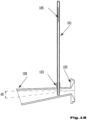
- the pool aerator with water recirculation circuit includes a spray body 100 and a intake pipe 101 of the atmospheric air.
- the spray body 100 consists of a frustoconical plastic tube, being provided at the smaller diameter end with a connecting means 102 to a recirculated water outlet/nozzle, in the pool, below the level of the pool water; the other end, larger in diameter, is free for the evacuation of the aspirated air mixed with recirculated water, in the pool water.
- the axis of the cylindrical guide 103 is vertical, so that between this and the longitudinal axis of the spray body there is an angle ( ⁇ ) between 10 - 20 degrees, an optimal angle and position to produce the maximum efficiency of the density of air bubbles dispersed in water.
- the air intake pipe 101 consists of a plastic pipe having an outer diameter that allows it to slide through the cylindrical guide 103, and a length that makes its upper third stand above the water.
- This pipe is closed at the upper end by a plug 104, being provided, also at this end, in a first embodiment, with a longitudinal slot 105 for air absorption, which ensures a low noise level during operation.
- the spray body 100 has the approximate dimensions: the outer diameter of 18 mm at the narrow end, the outer diameter of 43 mm at the opposite end, and a total length of about 195 mm.
- the aerator has, at the narrow end, cast, a cylindrical flange threaded on the outside, acting as a connecting means 102, having a hollow interior, also of frustoconical shape which is connected on the same diameter to a plastic tube of frustoconical shape of the spray body 100.
- the body of the spray 100 is screwed into the body of an existing nozzle in the pool wall (after removing the nozzle ball), thus ensuring the installation of the aerator in the pool.
- a cylindrical guide 103 cast, with an inner diameter of about 11 mm, a height of about 15 mm, vertically oriented, a guide in which the pipe is inserted by sliding air intake 101.
- the air intake pipe 101 consists of a cylindrical plastic pipe with an outer diameter of about 11 mm and a length of about 350 mm, which makes one end of it stand out of the water, the recommended dimensions for mounting the discharge nozzles being 300 mm below the water level.
- This pipe is closed at one end by a plug 104 and also provided, also at this end, with an air slot 105 of approximate dimensions: 0,5 mm width and 30 mm length. This slot ensures a low level of noise during the operation of the aerator according to the invention.
- the spray body 100 is mounted by screwing the threaded flange 102 into an existing pool discharge nozzle, the air intake pipe 101 is slid into the spray body 100 so that the air slot 105 remains on the surface of the water and the water jet exits through the discharge nozzle, due to the optimal angle of inclination and the position in relation to the spray body 100, sucks the air through the intake pipe 101; air and water are mixed in the spray body and then evacuated with pressure over a length of about 2 m resulting in a curtain of air bubbles 106 (illustrated in Fig.4 ).
- the body of the aerator (200a) comprises a rounded plastic object, having in the middle area a cylindrical portion (221), which continues at the end from the pool wall with a connecting means (202), corresponding to the outlet of the water recirculated in the pool, the middle portion (221) of the aerator body (200a) continuing with an area in the form of a hemispherical cap/dom (223), inside the aerator body (200a) being a Venturi tube made in the form of two frustoconical holes with a small common base, one for inlet (209) and the other (211) for mixing and discharging water mixed with air.
- the axes (A-A') and (B-B') of the two frustoconical trunks form an angle ( ⁇ ) between 10 and 20 degrees.
- the frustoconical mixing hole (211) communicates in the first third from the common base with a cylindrical hole (203) having a vertical axis, in which the lower end of the intake pipe (201) is inserted by sliding, until the inner wall of the frustoconical mixing and discharge hole (211) is reached.
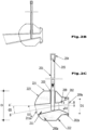
- the pool aerator according to the invention has two parts, preferably of plastic material - a pool aerator body 200a with rounded anti-impact shapes and an atmospheric air intake pipe 201 which is inserted into the aerator body, operating based on the Venturi principle, inside of the aerator body being found the pool aerator from Fig.1 , as shown schematically in Fig.2B , adjusted to be surrounded and to fit the dimensions of the rounded body, for reasons of impact protection, robustness and for an enhanced aesthetic appearance.
- the body of the pool aerator shall be mounted by means of a connection means 202 to the water recirculation circuit, at least in one of the existing outlets to the pools with water recirculation circuit (preferably to be mounted in all, otherwise it is necessary to block the outlets without aerators in order to equalize the water pressure at the outlet), holes located below the pool water level, and pipe 201 that sucks air from the atmosphere from the water surface, is attached to the spray body in a cylindrical hole 203 which communicates with said Venturi tube.
- the pipe 201 has an upper end closed with a cylindrical plug/lid 204, with an inner diameter larger than the outer diameter of the intake pipe 201, below which is provided an atmospheric air intake hole 205, hidden/masked by plug 204.
- the body 200a of the pool aerator with water recirculation circuit consists of a plastic object, generally round, having in the middle a cylindrical shape portion 221 of diameter D, this middle portion continuing at the end from the wall of the pool (which is mounted in the recirculated water discharge nozzle), with the connecting means 202, made in the form of a cylindrical portion with a diameter D1 smaller than the diameter D, the connection between them being made by a frustoconical portion 222.
- the connecting means 202 is provided with an external thread 202a corresponding to the recirculated water outlet in the pool, if it is provided with an internal thread.
- the middle portion 221 of the aerator body 200a is continued with a hemisphere-shaped portion (spherical caps) 223.
- the Venturi tube inside the body 200a of the aerator is made in the form of two frustoconical holes 209 and 211 having the small common base (neck) of diameter D2.
- the frustoconical inlet hole 209 is located mostly in the connecting means 202, has the horizontal axis A-A', and the inlet port 209a of the diameter D1.
- the frustoconical conical hole 211 for mixing and evacuating water mixed with air is located mostly inside the middle portion and the end of the hemispherical portion, having the longitudinal axis B-B' inclined with respect to the axis A-A' of the the frustoconical inlet hole 209, with an angle ⁇ around 10 - 20° (sexagesimal degrees), and the outlet 211a of diameter D3.
- the frustoconical hole 211 communicates in the first third from the common base, with a cylindrical hole 203 having the vertical axis (perpendicular to the axis A-A' of the frustoconical inlet hole 209 ). In the cylindrical hole 203 is inserted by sliding, until the inner wall of the frustoconical mixing and discharge hole 211 is reached, the lower end of the intake pipe 202, thus automatically reaching the maximum yield position and angle.
- the air intake tube 201 consists of a cylindrical pipe preferably made of plastic having an outer diameter that allows sliding through the cylindrical hole 203, and a length that makes its upper end stand above the water. This pipe is closed at the upper end by a plug 204, being also provided, also at this end, with an air absorption hole 205, round in shape or rectangular slot which ensures a low level of noise during operation.
- the intake pipe can be made of a single section or of several sections, for example two or three, tightly connected to each other.
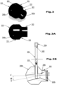
- Fig.2D shows, in section, the way in which the pool aerator 200a and the air intake pipe 201 are mounted in the existing nozzle in the wall of a swimming pool with reinforced concrete walls, according to the invention.
- the body 200b of the pool aerator has the connecting means 202 made in the form of a cylindrical portion of diameter D1, being elongated so that the inlet hole continues with a cylindrical hole 202b of the same diameter D1 with the large base of the cone, said cylindrical hole (202b) being threaded inwards (female threaded) corresponding to the recirculation of the water recirculated in the pool, if it is provided with external thread, and which ensures connection to the recirculation circuit of water.
- the body 200a or 200b of the pool aerator may be solid (made of homogeneous material) or may have a honeycomb structure with the provision of continuous surfaces for the aerator body (outer surface), for the Venturi 209-211 tube and for the cylindrical hole 203.
- the body of the sprayer 200a is made of plastic, honeycomb structure and has inside the frustoconical hole 209 with approximate dimensions: the diameter D1 of the inlet 209a of 40 mm and the diameter of the neck D2 of 18 mm, the frustoconical hole 211 having a diameter D3 of the outlet 211a of approximately 28 mm, the cylindrical hole 203 having a diameter slightly larger than 11 mm.
- the entire spray body of the aerator has a total length of about 90 mm and the diameter D of the middle portion of 80 mm.
- the air intake tube 201 consists of a cylindrical plastic pipe having an outer diameter of less than or equal to 11 mm and a length of about 350 mm, which makes an end rise at least 50 mm above the water level of the pool water (the recommended elevations for mounting the nozzles/discharge holes when constructing a pool are 300 mm below the water level).
- the spray body 200a or 200b is mounted by screwing the threads 202a and 202b into an existing pool discharge nozzle, the air intake pipe 201 is slid into the spray body so that the air intake hole 205 remains at the surface of the water and the water jet pushed by the pump of the circuit coming out of the discharge nozzle sucks the air through the intake pipe 201.
- Air and water are mixed in the body of the sprayer and evacuated with pressure over a length of about 2 m, resulting in a curtain of air bubbles 140 (illustrated in Fig.4 ).
- Fig.4 shows the top view and cross-section of a swimming pool (provided with a water recirculation circuit, which includes, among others, water filtration and treatment elements, a pump that absorbs water from the pool and discharges it back through some holes/discharge nozzles) in which two aerators according to the invention are mounted.
- a water recirculation circuit which includes, among others, water filtration and treatment elements, a pump that absorbs water from the pool and discharges it back through some holes/discharge nozzles
- two aerators according to the invention are mounted.
Landscapes
- Engineering & Computer Science (AREA)
- Architecture (AREA)
- Chemical & Material Sciences (AREA)
- Chemical Kinetics & Catalysis (AREA)
- Civil Engineering (AREA)
- Structural Engineering (AREA)
- Water Supply & Treatment (AREA)
- Aeration Devices For Treatment Of Activated Polluted Sludge (AREA)
Claims (8)
- Aérateur destiné à une piscine pour son utilisation dans des piscines équipées d'un circuit de recyclage de l'eau, ledit aérateur destiné à une piscine comprenant un corps de pulvérisation qui comprend un canal tubulaire de type Venturi et un tuyau pour l'admission de l'air atmosphérique, destiné à l'admission d'air à partir d'un endroit situé au-dessus de la piscine ; dans lequel ledit corps de pulvérisation est constitué d'un tube tronconique (100) en matière plastique, qui est muni, à l'extrémité possédant un plus petit diamètre, d'un moyen de raccordement (102) à une sortie pour l'eau de recyclage dans la piscine, en dessous du niveau de l'eau de la piscine, l'autre extrémité, qui possède un plus grand diamètre étant libre pour la sortie sous la forme d'un jet de l'air aspiré, de manière conjointe avec l'eau qui a été recyclée, dans l'eau de la piscine, l'axe du tube tronconique (100) en matière plastique étant incliné en formant un angle (α) entre 10 et 20 degrés par rapport à la perpendiculaire au plan de base du moyen de raccordement (102), et dans le premier tiers de la longueur du corps de pulvérisation (100) à partir de l'extrémité munie du moyen de raccordement (102), ledit corps de pulvérisation (100) est muni d'une branche cylindrique (103) qui fait également office de guide, dans laquelle l'extrémité inférieure du tuyau (101) pour l'admission de l'air a été insérée en la faisant coulisser jusqu'à ce qu'elle atteigne la paroi interne du tube.
- Aérateur destiné à une piscine selon la revendication 1, caractérisé en ce que le moyen de raccordement (102) est une bride cylindrique possédant un filet de vis sur son côté externe, et qui possède également un intérieur creux qui possède également une configuration de forme tronconique, qui est relié au tube tronconique en matière plastique du corps de pulvérisation (100), la bride filetée pouvant être introduite par vissage dans la buse existante dans la paroi de la piscine, pour ainsi garantir le montage de l'aérateur dans la piscine.
- Aérateur destiné à une piscine selon la revendication 1, caractérisé en ce que le tuyau (101) pour l'admission de l'air est constitué d'un tuyau en matière plastique qui possède un diamètre externe qui lui permet de coulisser à travers le guide cylindrique (103) et une longueur qui fait en sorte que son tiers supérieur s'élève au-dessus de l'eau, le tuyau étant fermé à l'extrémité supérieure par un bouchon (104) et étant muni, également à cet effet, d'une fente longitudinale (105) pour l'absorption de l'air, ce qui garantit un faible niveau de bruit au cours de la mise en oeuvre.
- Aérateur hémisphérique destiné à une piscine pour son utilisation dans des piscines équipées d'un circuit de recyclage de l'eau, ledit aérateur hémisphérique destiné à une piscine comprenant un corps de pulvérisation (200a) qui est réalisé sous la forme d'un tube de type Venturi ainsi qu'un tuyau (201) pour l'admission de l'air atmosphérique; dans lequel le corps de pulvérisation (200a) de l'aérateur comprend un objet en matière plastique de forme arrondie, qui possède, dans la zone médiane, une portion cylindrique (221) qui se prolonge, à l'extrémité, au cours de l'utilisation, à proximité de la paroi de piscine, sous la forme d'un moyen de raccordement (202) d'une manière qui correspond à la sortie pour l'eau qui a été recyclée dans la piscine, la zone médiane du corps de pulvérisation (200a) de l'aérateur se prolongeant sous la forme d'une zone qui prend la forme d'un capot de forme hémisphérique (223), un tube de type Venturi, qui est réalisé sous la forme de deux trous tronconiques comprenant une petite base commune - un trou d'entrée (209) et un trou de mélange (211) pour le mélange et l'évacuation de l'eau qui a été mélangée avec de l'air - étant situé à l'intérieur du corps de pulvérisation (200a) de l'aérateur, le trou d'entrée (209) de forme tronconique étant situé, pour la majeure partie, entre les moyens de raccordement (202) qui possèdent un axe horizontal (A-A'), et le trou de mélange (211) étant disposé principalement dans la zone médiane du moyen de raccordement, et la portion sphérique du corps de l'aérateur possédant un axe longitudinal (B-B') qui est incliné par rapport à l'axe horizontal (A-A') du trou d'entrée (209) de forme tronconique en formant un angle (α) d'environ 10 à 20 degrés, le trou de mélange (211) de forme tronconique entrant en communication avec, dans le premier tiers à partir de la base, avec un trou cylindrique (203) qui possède un axe vertical, dans lequel l'extrémité inférieure du tuyau d'admission a été insérée par coulissement, jusqu'à ce que l'on atteigne (201) la paroi interne du trou de mélange et d'évacuation (211) de forme tronconique.
- Aérateur hémisphérique destiné à une piscine selon la revendication 4, caractérisé en ce que le moyen de raccordement (202) est réalisé sous la forme d'une portion cylindrique dont le diamètre (D1) est inférieur au diamètre (D) de la portion médiane, le raccordement entre eux étant réalisé par une portion tronconique (222), le moyen de raccordement (202) étant muni d'un filet de vis externe (202a) de manière correspondante avec la sortie utilisée pour l'évacuation de l'eau qui a été recyclée, dans la piscine.
- Aérateur hémisphérique destiné à une piscine selon la revendication 4, caractérisé en ce que le moyen de raccordement (202) du corps (200b) de l'aérateur destiné à une piscine est réalisé sous la forme d'une portion cylindrique, qui est allongée d'une manière telle que le trou d'admission (209) de forme tronconique se prolonge en un trou cylindrique (202b) dont le diamètre est identique à celui de la grande base du cône, ledit trou cylindrique (202b) étant taraudé d'une manière qui correspond au filet de vis externe de la sortie utilisée pour l'évacuation de l'eau qui a été recyclée dans la piscine.
- Aérateur hémisphérique destiné à une piscine selon les revendications 4 à 6, caractérisé en ce que le tuyau d'admission est fermé à l'extrémité supérieure par un bouchon (204) et est également muni, également à cet effet, d'un trou (205) pour l'admission de l'air, qui reste caché en dessous du bouchon, qui possède une configuration de forme arrondie et qui garantit un faible niveau de bruit au cours de la mise en oeuvre.
- Aérateur destiné à une piscine selon l'une quelconque des revendications 1 à 3 ou aérateur hémisphérique destiné à une piscine selon l'une quelconque des revendications 4 à 7, caractérisé en ce que le tuyau d'admission (101, 201) est réalisé à partir d'un tronçon unique ou à partir de plusieurs tronçons, qui sont reliés fermement les uns aux autres.
Applications Claiming Priority (3)
| Application Number | Priority Date | Filing Date | Title |
|---|---|---|---|
| RO201900453A RO133709B1 (ro) | 2019-07-25 | 2019-07-25 | Aerator piscină |
| ROU201900036U RO201900036U1 (ro) | 2019-11-01 | 2019-11-01 | Aerator piscină semisferic |
| PCT/RO2020/000009 WO2021015634A1 (fr) | 2019-07-25 | 2020-06-16 | Aérateur de piscine |
Publications (4)
| Publication Number | Publication Date |
|---|---|
| EP4004308A1 EP4004308A1 (fr) | 2022-06-01 |
| EP4004308A4 EP4004308A4 (fr) | 2023-08-16 |
| EP4004308B1 true EP4004308B1 (fr) | 2024-11-20 |
| EP4004308C0 EP4004308C0 (fr) | 2024-11-20 |
Family
ID=74193618
Family Applications (1)
| Application Number | Title | Priority Date | Filing Date |
|---|---|---|---|
| EP20844768.0A Active EP4004308B1 (fr) | 2019-07-25 | 2020-06-16 | Aérateur de piscine |
Country Status (3)
| Country | Link |
|---|---|
| US (1) | US11885148B2 (fr) |
| EP (1) | EP4004308B1 (fr) |
| WO (1) | WO2021015634A1 (fr) |
Family Cites Families (21)
| Publication number | Priority date | Publication date | Assignee | Title |
|---|---|---|---|---|
| US3067435A (en) * | 1961-08-25 | 1962-12-11 | Jacuzzi Bros Inc | Hydrotherapeutic installation for swimming pools and the like |
| US3396722A (en) * | 1965-10-04 | 1968-08-13 | Albert W. Lindberg Jr. | Combined aeration and hydrotherapy apparatus |
| US3587976A (en) * | 1969-02-13 | 1971-06-28 | Jacuzzi Research Inc | Tub-installable hydrotherapy assembly |
| US3577571A (en) | 1969-03-19 | 1971-05-04 | Marine Swimming Pool Equipment | Combination cleaning, fountain and therapeutic whirlpool apparatus for swimming pools |
| US3745994A (en) * | 1971-11-15 | 1973-07-17 | R Kane | Adjustable hydrotherapy jet producing device |
| CH561059A5 (en) * | 1972-06-27 | 1975-04-30 | Stejskal Alfred E | Swimming pool current producer for massaging - air admixed by jet on outlet from suction pump delivery line |
| US3810464A (en) * | 1972-07-17 | 1974-05-14 | Raymond Lee Organization Inc | Whirlpool bath unit |
| US3904393A (en) * | 1973-07-13 | 1975-09-09 | Raymond A Morse | Venturi-type water aerator |
| US3943580A (en) * | 1974-12-23 | 1976-03-16 | Carter Don W | Therapeutic pool system |
| US4308138A (en) | 1978-07-10 | 1981-12-29 | Woltman Robert B | Treating means for bodies of water |
| GB8917882D0 (en) * | 1989-08-04 | 1989-09-20 | Ph Pool Services Ltd | Jet units for whirlpool-bath systems |
| CA2027297A1 (fr) * | 1990-10-10 | 1992-04-11 | Mario Houle | Procede pour empecher la formation d'algues dans une piscine |
| US5172432A (en) * | 1992-01-17 | 1992-12-22 | Fernand Beland | Swimming pool aerating device |
| IT1266669B1 (it) * | 1993-11-04 | 1997-01-09 | Teuco Guzzini Srl | Dispositivo di idromassaggio localizzato |
| FR2760356B1 (fr) * | 1997-03-06 | 1999-06-04 | Max Roumagnac | Equipement notamment d'hydromassage ou analogue adaptable aux bouches de refoulement de piscines |
| US6237897B1 (en) | 1999-04-29 | 2001-05-29 | Antonio Marina | Oxygenator |
| US6138293A (en) | 1999-06-14 | 2000-10-31 | Caretaker Systems, Inc. | Adjustable mounting collar for a retractable cleaning head |
| ES1044076Y (es) | 1999-08-04 | 2000-08-16 | Sacopa Sa | Dispositivo para la limpieza de fondos de piscinas. |
| US6398194B1 (en) | 1999-11-29 | 2002-06-04 | Tsung-Hsin Tsai | Water pressure-type aeration device |
| CA3037677C (fr) * | 2015-05-12 | 2021-05-18 | Intex Marketing Ltd. | Dispositif de pulverisation d'eau d'une piscine hors sol |
| US10202781B1 (en) | 2016-04-19 | 2019-02-12 | Christopher Orosco | Swimming pool aerator |
-
2020
- 2020-06-16 EP EP20844768.0A patent/EP4004308B1/fr active Active
- 2020-06-16 WO PCT/RO2020/000009 patent/WO2021015634A1/fr not_active Ceased
- 2020-06-16 US US17/423,841 patent/US11885148B2/en active Active
Also Published As
| Publication number | Publication date |
|---|---|
| WO2021015634A1 (fr) | 2021-01-28 |
| EP4004308C0 (fr) | 2024-11-20 |
| US20220081922A1 (en) | 2022-03-17 |
| US11885148B2 (en) | 2024-01-30 |
| EP4004308A4 (fr) | 2023-08-16 |
| EP4004308A1 (fr) | 2022-06-01 |
Similar Documents
| Publication | Publication Date | Title |
|---|---|---|
| ES2376303T3 (es) | Aparato y procedimiento para oxigenar aguas residuales. | |
| US20070267359A1 (en) | Aeration method of pool water and apparatus there of | |
| KR100297539B1 (ko) | 오수정화처리장치 | |
| EP3315024B1 (fr) | Dispositif de nettoyage pour étangs | |
| CN201204873Y (zh) | 沉淀集污与喷水式增氧的室内循环水养鱼池 | |
| TWM560276U (zh) | 微納米氣泡淋浴花灑 | |
| EP4004308B1 (fr) | Aérateur de piscine | |
| US5172432A (en) | Swimming pool aerating device | |
| US8128070B1 (en) | Venturi aeration circulation system | |
| CN206993955U (zh) | 一种园林智能环保喷水装置 | |
| DE69933508T2 (de) | Wirbelgenerator für feine bläschen und verfahren | |
| CN201821766U (zh) | 一种用于分离海水中有机物的蛋白质分离器 | |
| CN108002562A (zh) | 用于水处理的曝气装置及水处理设备和水处理方法 | |
| CN108178348A (zh) | 强正压喷雾曝气系统 | |
| CN208308533U (zh) | 用于水处理的曝气装置及水处理设备 | |
| US20090206497A1 (en) | Liquid waste aeration system and method | |
| KR20100004735A (ko) | 이동용 수질정화장치 | |
| DE3030416C2 (de) | Anordnung zur Belüftung des häuslichen und/oder industriellen Abwassers | |
| RO133709B1 (ro) | Aerator piscină | |
| CN106931529A (zh) | 空气净化处理装置 | |
| CN213358896U (zh) | 喷水池 | |
| KR102874297B1 (ko) | 악취 제거 및 분수노즐 막힘방지 기능을 포함하는 분수장치 및 그 분수 막힘 방지 방법 | |
| CN2205631Y (zh) | 水陆两用活鱼贮运机 | |
| CN214781045U (zh) | 一种能够产生纳米气泡的太阳能涌泉曝气机 | |
| CN211198804U (zh) | 一种循环水增氧过滤设备 |
Legal Events
| Date | Code | Title | Description |
|---|---|---|---|
| STAA | Information on the status of an ep patent application or granted ep patent |
Free format text: STATUS: THE INTERNATIONAL PUBLICATION HAS BEEN MADE |
|
| PUAI | Public reference made under article 153(3) epc to a published international application that has entered the european phase |
Free format text: ORIGINAL CODE: 0009012 |
|
| STAA | Information on the status of an ep patent application or granted ep patent |
Free format text: STATUS: REQUEST FOR EXAMINATION WAS MADE |
|
| 17P | Request for examination filed |
Effective date: 20220222 |
|
| AK | Designated contracting states |
Kind code of ref document: A1 Designated state(s): AL AT BE BG CH CY CZ DE DK EE ES FI FR GB GR HR HU IE IS IT LI LT LU LV MC MK MT NL NO PL PT RO RS SE SI SK SM TR |
|
| DAV | Request for validation of the european patent (deleted) | ||
| DAX | Request for extension of the european patent (deleted) | ||
| A4 | Supplementary search report drawn up and despatched |
Effective date: 20230714 |
|
| RIC1 | Information provided on ipc code assigned before grant |
Ipc: B01F 23/232 20220101ALI20230710BHEP Ipc: B01F 23/454 20220101ALI20230710BHEP Ipc: B01F 25/312 20220101ALI20230710BHEP Ipc: B01F 25/53 20220101ALI20230710BHEP Ipc: E04H 4/16 20060101ALI20230710BHEP Ipc: E04H 4/14 20060101ALI20230710BHEP Ipc: A61H 33/02 20060101ALI20230710BHEP Ipc: E04H 4/12 20060101AFI20230710BHEP |
|
| GRAP | Despatch of communication of intention to grant a patent |
Free format text: ORIGINAL CODE: EPIDOSNIGR1 |
|
| STAA | Information on the status of an ep patent application or granted ep patent |
Free format text: STATUS: GRANT OF PATENT IS INTENDED |
|
| GRAS | Grant fee paid |
Free format text: ORIGINAL CODE: EPIDOSNIGR3 |
|
| RIC1 | Information provided on ipc code assigned before grant |
Ipc: B01F 23/2326 20220101ALI20240515BHEP Ipc: B01F 23/232 20220101ALI20240515BHEP Ipc: B01F 23/454 20220101ALI20240515BHEP Ipc: B01F 25/312 20220101ALI20240515BHEP Ipc: B01F 25/53 20220101ALI20240515BHEP Ipc: E04H 4/16 20060101ALI20240515BHEP Ipc: E04H 4/14 20060101ALI20240515BHEP Ipc: A61H 33/02 20060101ALI20240515BHEP Ipc: E04H 4/12 20060101AFI20240515BHEP |
|
| INTG | Intention to grant announced |
Effective date: 20240611 |
|
| GRAA | (expected) grant |
Free format text: ORIGINAL CODE: 0009210 |
|
| STAA | Information on the status of an ep patent application or granted ep patent |
Free format text: STATUS: THE PATENT HAS BEEN GRANTED |
|
| AK | Designated contracting states |
Kind code of ref document: B1 Designated state(s): AL AT BE BG CH CY CZ DE DK EE ES FI FR GB GR HR HU IE IS IT LI LT LU LV MC MK MT NL NO PL PT RO RS SE SI SK SM TR |
|
| REG | Reference to a national code |
Ref country code: GB Ref legal event code: FG4D |
|
| REG | Reference to a national code |
Ref country code: CH Ref legal event code: EP |
|
| REG | Reference to a national code |
Ref country code: DE Ref legal event code: R096 Ref document number: 602020041806 Country of ref document: DE |
|
| REG | Reference to a national code |
Ref country code: IE Ref legal event code: FG4D |
|
| U01 | Request for unitary effect filed |
Effective date: 20241209 |
|
| U07 | Unitary effect registered |
Designated state(s): AT BE BG DE DK EE FI FR IT LT LU LV MT NL PT RO SE SI Effective date: 20241219 |
|
| PG25 | Lapsed in a contracting state [announced via postgrant information from national office to epo] |
Ref country code: IS Free format text: LAPSE BECAUSE OF FAILURE TO SUBMIT A TRANSLATION OF THE DESCRIPTION OR TO PAY THE FEE WITHIN THE PRESCRIBED TIME-LIMIT Effective date: 20250320 Ref country code: HR Free format text: LAPSE BECAUSE OF FAILURE TO SUBMIT A TRANSLATION OF THE DESCRIPTION OR TO PAY THE FEE WITHIN THE PRESCRIBED TIME-LIMIT Effective date: 20241120 |
|
| PG25 | Lapsed in a contracting state [announced via postgrant information from national office to epo] |
Ref country code: ES Free format text: LAPSE BECAUSE OF FAILURE TO SUBMIT A TRANSLATION OF THE DESCRIPTION OR TO PAY THE FEE WITHIN THE PRESCRIBED TIME-LIMIT Effective date: 20241120 |
|
| PG25 | Lapsed in a contracting state [announced via postgrant information from national office to epo] |
Ref country code: NO Free format text: LAPSE BECAUSE OF FAILURE TO SUBMIT A TRANSLATION OF THE DESCRIPTION OR TO PAY THE FEE WITHIN THE PRESCRIBED TIME-LIMIT Effective date: 20250220 |
|
| PG25 | Lapsed in a contracting state [announced via postgrant information from national office to epo] |
Ref country code: GR Free format text: LAPSE BECAUSE OF FAILURE TO SUBMIT A TRANSLATION OF THE DESCRIPTION OR TO PAY THE FEE WITHIN THE PRESCRIBED TIME-LIMIT Effective date: 20250221 |
|
| PG25 | Lapsed in a contracting state [announced via postgrant information from national office to epo] |
Ref country code: PL Free format text: LAPSE BECAUSE OF FAILURE TO SUBMIT A TRANSLATION OF THE DESCRIPTION OR TO PAY THE FEE WITHIN THE PRESCRIBED TIME-LIMIT Effective date: 20241120 |
|
| PG25 | Lapsed in a contracting state [announced via postgrant information from national office to epo] |
Ref country code: RS Free format text: LAPSE BECAUSE OF FAILURE TO SUBMIT A TRANSLATION OF THE DESCRIPTION OR TO PAY THE FEE WITHIN THE PRESCRIBED TIME-LIMIT Effective date: 20250220 |
|
| REG | Reference to a national code |
Ref country code: GB Ref legal event code: 732E Free format text: REGISTERED BETWEEN 20250605 AND 20250611 |
|
| PG25 | Lapsed in a contracting state [announced via postgrant information from national office to epo] |
Ref country code: SM Free format text: LAPSE BECAUSE OF FAILURE TO SUBMIT A TRANSLATION OF THE DESCRIPTION OR TO PAY THE FEE WITHIN THE PRESCRIBED TIME-LIMIT Effective date: 20241120 |
|
| PGFP | Annual fee paid to national office [announced via postgrant information from national office to epo] |
Ref country code: GB Payment date: 20250610 Year of fee payment: 6 |
|
| REG | Reference to a national code |
Ref country code: CH Ref legal event code: PK Free format text: BERICHTIGUNGEN |
|
| U20 | Renewal fee for the european patent with unitary effect paid |
Year of fee payment: 6 Effective date: 20250610 |
|
| PG25 | Lapsed in a contracting state [announced via postgrant information from national office to epo] |
Ref country code: SK Free format text: LAPSE BECAUSE OF FAILURE TO SUBMIT A TRANSLATION OF THE DESCRIPTION OR TO PAY THE FEE WITHIN THE PRESCRIBED TIME-LIMIT Effective date: 20241120 |
|
| PG25 | Lapsed in a contracting state [announced via postgrant information from national office to epo] |
Ref country code: CZ Free format text: LAPSE BECAUSE OF FAILURE TO SUBMIT A TRANSLATION OF THE DESCRIPTION OR TO PAY THE FEE WITHIN THE PRESCRIBED TIME-LIMIT Effective date: 20241120 |
|
| PGFP | Annual fee paid to national office [announced via postgrant information from national office to epo] |
Ref country code: IE Payment date: 20250613 Year of fee payment: 6 |
|
| RAP2 | Party data changed (patent owner data changed or rights of a patent transferred) |
Owner name: S G H (MOULDS) LTD |
|
| RIN2 | Information on inventor provided after grant (corrected) |
Inventor name: CHIVULESCU, OCTAVIAN PAUL |
|
| U1K | Transfer of rights of the unitary patent after the registration of the unitary effect |
Owner name: S G H (MOULDS) LTD; GB |
|
| U1N | Appointed representative for the unitary patent procedure changed after the registration of the unitary effect |
Representative=s name: NOBLE, FREDERICK; GB |
|
| PLBE | No opposition filed within time limit |
Free format text: ORIGINAL CODE: 0009261 |
|
| STAA | Information on the status of an ep patent application or granted ep patent |
Free format text: STATUS: NO OPPOSITION FILED WITHIN TIME LIMIT |
|
| 26N | No opposition filed |
Effective date: 20250821 |
|
| REG | Reference to a national code |
Ref country code: CH Ref legal event code: H13 Free format text: ST27 STATUS EVENT CODE: U-0-0-H10-H13 (AS PROVIDED BY THE NATIONAL OFFICE) Effective date: 20260127 |
|
| PG25 | Lapsed in a contracting state [announced via postgrant information from national office to epo] |
Ref country code: MC Free format text: LAPSE BECAUSE OF FAILURE TO SUBMIT A TRANSLATION OF THE DESCRIPTION OR TO PAY THE FEE WITHIN THE PRESCRIBED TIME-LIMIT Effective date: 20241120 |
|
| PG25 | Lapsed in a contracting state [announced via postgrant information from national office to epo] |
Ref country code: CH Free format text: LAPSE BECAUSE OF NON-PAYMENT OF DUE FEES Effective date: 20250630 |