EP4004310B1 - Procédé de production d'un segment de tour et segment de tour - Google Patents
Procédé de production d'un segment de tour et segment de tour Download PDFInfo
- Publication number
- EP4004310B1 EP4004310B1 EP20745178.2A EP20745178A EP4004310B1 EP 4004310 B1 EP4004310 B1 EP 4004310B1 EP 20745178 A EP20745178 A EP 20745178A EP 4004310 B1 EP4004310 B1 EP 4004310B1
- Authority
- EP
- European Patent Office
- Prior art keywords
- tower
- plate
- section
- thickness
- constant
- Prior art date
- Legal status (The legal status is an assumption and is not a legal conclusion. Google has not performed a legal analysis and makes no representation as to the accuracy of the status listed.)
- Active
Links
Images








Classifications
-
- E—FIXED CONSTRUCTIONS
- E04—BUILDING
- E04H—BUILDINGS OR LIKE STRUCTURES FOR PARTICULAR PURPOSES; SWIMMING OR SPLASH BATHS OR POOLS; MASTS; FENCING; TENTS OR CANOPIES, IN GENERAL
- E04H12/00—Towers; Masts or poles; Chimney stacks; Water-towers; Methods of erecting such structures
- E04H12/02—Structures made of specified materials
- E04H12/08—Structures made of specified materials of metal
-
- B—PERFORMING OPERATIONS; TRANSPORTING
- B21—MECHANICAL METAL-WORKING WITHOUT ESSENTIALLY REMOVING MATERIAL; PUNCHING METAL
- B21C—MANUFACTURE OF METAL SHEETS, WIRE, RODS, TUBES, PROFILES OR LIKE SEMI-MANUFACTURED PRODUCTS OTHERWISE THAN BY ROLLING; AUXILIARY OPERATIONS USED IN CONNECTION WITH METAL-WORKING WITHOUT ESSENTIALLY REMOVING MATERIAL
- B21C37/00—Manufacture of metal sheets, rods, wire, tubes, profiles or like semi-manufactured products, not otherwise provided for; Manufacture of tubes of special shape
- B21C37/06—Manufacture of metal sheets, rods, wire, tubes, profiles or like semi-manufactured products, not otherwise provided for; Manufacture of tubes of special shape of tubes or metal hoses; Combined procedures for making tubes, e.g. for making multi-wall tubes
- B21C37/15—Making tubes of special shape; Making tube fittings
- B21C37/16—Making tubes with varying diameter in longitudinal direction
- B21C37/18—Making tubes with varying diameter in longitudinal direction conical tubes
- B21C37/185—Making tubes with varying diameter in longitudinal direction conical tubes starting from sheet material
-
- E—FIXED CONSTRUCTIONS
- E04—BUILDING
- E04H—BUILDINGS OR LIKE STRUCTURES FOR PARTICULAR PURPOSES; SWIMMING OR SPLASH BATHS OR POOLS; MASTS; FENCING; TENTS OR CANOPIES, IN GENERAL
- E04H12/00—Towers; Masts or poles; Chimney stacks; Water-towers; Methods of erecting such structures
- E04H12/02—Structures made of specified materials
- E04H12/08—Structures made of specified materials of metal
- E04H12/085—Details of flanges for tubular masts
-
- E—FIXED CONSTRUCTIONS
- E04—BUILDING
- E04H—BUILDINGS OR LIKE STRUCTURES FOR PARTICULAR PURPOSES; SWIMMING OR SPLASH BATHS OR POOLS; MASTS; FENCING; TENTS OR CANOPIES, IN GENERAL
- E04H12/00—Towers; Masts or poles; Chimney stacks; Water-towers; Methods of erecting such structures
- E04H12/34—Arrangements for erecting or lowering towers, masts, poles, chimney stacks, or the like
- E04H12/342—Arrangements for stacking tower sections on top of each other
-
- F—MECHANICAL ENGINEERING; LIGHTING; HEATING; WEAPONS; BLASTING
- F03—MACHINES OR ENGINES FOR LIQUIDS; WIND, SPRING, OR WEIGHT MOTORS; PRODUCING MECHANICAL POWER OR A REACTIVE PROPULSIVE THRUST, NOT OTHERWISE PROVIDED FOR
- F03D—WIND MOTORS
- F03D13/00—Assembly, mounting or commissioning of wind motors; Arrangements specially adapted for transporting wind motor components
- F03D13/20—Arrangements for mounting or supporting wind motors; Masts or towers for wind motors
-
- F—MECHANICAL ENGINEERING; LIGHTING; HEATING; WEAPONS; BLASTING
- F03—MACHINES OR ENGINES FOR LIQUIDS; WIND, SPRING, OR WEIGHT MOTORS; PRODUCING MECHANICAL POWER OR A REACTIVE PROPULSIVE THRUST, NOT OTHERWISE PROVIDED FOR
- F03D—WIND MOTORS
- F03D9/00—Adaptations of wind motors for special use; Combinations of wind motors with apparatus driven thereby; Wind motors specially adapted for installation in particular locations
- F03D9/30—Wind motors specially adapted for installation in particular locations
- F03D9/34—Wind motors specially adapted for installation in particular locations on stationary objects or on stationary man-made structures
-
- F—MECHANICAL ENGINEERING; LIGHTING; HEATING; WEAPONS; BLASTING
- F05—INDEXING SCHEMES RELATING TO ENGINES OR PUMPS IN VARIOUS SUBCLASSES OF CLASSES F01-F04
- F05B—INDEXING SCHEME RELATING TO WIND, SPRING, WEIGHT, INERTIA OR LIKE MOTORS, TO MACHINES OR ENGINES FOR LIQUIDS COVERED BY SUBCLASSES F03B, F03D AND F03G
- F05B2230/00—Manufacture
- F05B2230/20—Manufacture essentially without removing material
- F05B2230/23—Manufacture essentially without removing material by permanently joining parts together
- F05B2230/232—Manufacture essentially without removing material by permanently joining parts together by welding
-
- F—MECHANICAL ENGINEERING; LIGHTING; HEATING; WEAPONS; BLASTING
- F05—INDEXING SCHEMES RELATING TO ENGINES OR PUMPS IN VARIOUS SUBCLASSES OF CLASSES F01-F04
- F05B—INDEXING SCHEME RELATING TO WIND, SPRING, WEIGHT, INERTIA OR LIKE MOTORS, TO MACHINES OR ENGINES FOR LIQUIDS COVERED BY SUBCLASSES F03B, F03D AND F03G
- F05B2230/00—Manufacture
- F05B2230/20—Manufacture essentially without removing material
- F05B2230/26—Manufacture essentially without removing material by rolling
-
- F—MECHANICAL ENGINEERING; LIGHTING; HEATING; WEAPONS; BLASTING
- F05—INDEXING SCHEMES RELATING TO ENGINES OR PUMPS IN VARIOUS SUBCLASSES OF CLASSES F01-F04
- F05B—INDEXING SCHEME RELATING TO WIND, SPRING, WEIGHT, INERTIA OR LIKE MOTORS, TO MACHINES OR ENGINES FOR LIQUIDS COVERED BY SUBCLASSES F03B, F03D AND F03G
- F05B2240/00—Components
- F05B2240/90—Mounting on supporting structures or systems
- F05B2240/91—Mounting on supporting structures or systems on a stationary structure
- F05B2240/912—Mounting on supporting structures or systems on a stationary structure on a tower
-
- F—MECHANICAL ENGINEERING; LIGHTING; HEATING; WEAPONS; BLASTING
- F05—INDEXING SCHEMES RELATING TO ENGINES OR PUMPS IN VARIOUS SUBCLASSES OF CLASSES F01-F04
- F05B—INDEXING SCHEME RELATING TO WIND, SPRING, WEIGHT, INERTIA OR LIKE MOTORS, TO MACHINES OR ENGINES FOR LIQUIDS COVERED BY SUBCLASSES F03B, F03D AND F03G
- F05B2280/00—Materials; Properties thereof
- F05B2280/10—Inorganic materials, e.g. metals
-
- Y—GENERAL TAGGING OF NEW TECHNOLOGICAL DEVELOPMENTS; GENERAL TAGGING OF CROSS-SECTIONAL TECHNOLOGIES SPANNING OVER SEVERAL SECTIONS OF THE IPC; TECHNICAL SUBJECTS COVERED BY FORMER USPC CROSS-REFERENCE ART COLLECTIONS [XRACs] AND DIGESTS
- Y02—TECHNOLOGIES OR APPLICATIONS FOR MITIGATION OR ADAPTATION AGAINST CLIMATE CHANGE
- Y02E—REDUCTION OF GREENHOUSE GAS [GHG] EMISSIONS, RELATED TO ENERGY GENERATION, TRANSMISSION OR DISTRIBUTION
- Y02E10/00—Energy generation through renewable energy sources
- Y02E10/70—Wind energy
- Y02E10/72—Wind turbines with rotation axis in wind direction
-
- Y—GENERAL TAGGING OF NEW TECHNOLOGICAL DEVELOPMENTS; GENERAL TAGGING OF CROSS-SECTIONAL TECHNOLOGIES SPANNING OVER SEVERAL SECTIONS OF THE IPC; TECHNICAL SUBJECTS COVERED BY FORMER USPC CROSS-REFERENCE ART COLLECTIONS [XRACs] AND DIGESTS
- Y02—TECHNOLOGIES OR APPLICATIONS FOR MITIGATION OR ADAPTATION AGAINST CLIMATE CHANGE
- Y02P—CLIMATE CHANGE MITIGATION TECHNOLOGIES IN THE PRODUCTION OR PROCESSING OF GOODS
- Y02P70/00—Climate change mitigation technologies in the production process for final industrial or consumer products
- Y02P70/50—Manufacturing or production processes characterised by the final manufactured product
Definitions
- the invention relates to a manufacturing method for producing a tower segment, a tower section, and a tower section for a tower, in particular for a tower of a wind turbine. Furthermore, the invention relates to a tower segment, a tower section, and a tower section for a tower, in particular for a tower of a wind turbine, to a tower, and to a wind turbine.
- a tower such as a wind turbine tower, is typically operated for several decades. It is generally not replaceable and therefore designed for a relatively long service life. However, such a tower, especially for wind turbines, contributes significantly to the overall cost of manufacturing a wind turbine.
- EP 2 615 226 B1 relates to a steel tube support structure to be used as a tower of a wind turbine and a method for producing the steel tube support structure, comprising circular steel tubes, each obtained by forming at least one steel plate having one or more sections in which the plate thickness varies in the rolling direction, into a ring shape.
- the trend toward larger rotor diameters and rated power of wind turbines is increasing this need.
- This development leads to larger towers that are subject to greater loads, which requires additional resources—such as time, materials, and personnel—and thus higher costs to achieve the required service life despite the increasing load.
- German Patent and Trademark Office has searched the following prior art in the priority application for the present application: US 8 752 337 B2 , EP 2 615 226 B1 , JP 2005 - 264 535 A , Hau, Erich: Wind turbines, 6th ed., Berlin: Springer Vieweg, brochure "Perfecti on that leaves no one cold: Power tool solutions before and after welding.” from metabo, 72622 Nürtingen, printing note 09/17.
- This object is achieved by a manufacturing method for producing a tower segment of a tower according to claim 1.
- Wind turbine towers both in their installed state and in operation, typically have a vertical longitudinal axis and an annular cross-section orthogonal to this longitudinal axis.
- This annular cross-section can, for example, be circular or elliptical, or even polygonal in shape.
- the term "annular” refers not only to a circular or elliptical configuration, but also to a polygonal and/or polygonal configuration, as well as other configurations with multiple straight or curved sections.
- the installation state is understood here in particular to mean a state that refers to the vertically aligned tower, which – provided a correspondingly operational nacelle with a rotor is arranged on the tower – also corresponds to the operating state of the wind turbine.
- a substantially horizontal alignment of the longitudinal axis e.g., during manufacture and/or assembly and/or transport of the tower or parts thereof, is not meant here as the installation state.
- the alignments described for the installation state must be adapted accordingly during manufacture and/or assembly and/or transport to the temporarily non-vertically aligned longitudinal axis of the tower or part thereof.
- a tower segment is understood here as a part of an annular tower section, i.e., as an element that extends only over part of the circumference of the tower.
- Longitudinal joints that are essentially vertically or longitudinally aligned can generally be formed between the tower segments in the installed state and in the operating state. It is known that tower segments can, for example, have the shape of a shell segment of a cylinder, cone, or truncated cone.
- Two or more tower sections can form a tower section; as such, the tower section extends longitudinally only over part of the length of the tower section.
- a tower section is preferably formed from several annular tower sections, wherein essentially horizontally oriented circumferential joints can be formed between the annular tower sections in the installed state and in the operating state.
- a tower can comprise several tower sections arranged vertically one above the other in the installed state and in the operating state of the wind turbine. Between the tower sections arranged one above the other, essentially horizontally or circumferentially oriented circumferential joints can generally be formed in the installed state and in the operating state.
- a tower section is understood here as a part of a tower, i.e., an element that extends longitudinally only over a portion of the tower's length.
- a tower can comprise several tower sections arranged vertically one above the other in the installed and operating state of the wind turbine.
- the tower sections preferably have connecting elements at their upper and/or lower ends, by means of which the tower sections can be fastened to one another, in particular by screwing them together.
- Wind turbine towers typically taper from their bottom to their top.
- the alignment of the tower wall of a tapered tower typically deviates from the vertical by only a few degrees.
- alignments particularly in the installed or operating state, such as top, bottom, radial, horizontal, vertical, tangential, longitudinal, circumference, curvature, radius, etc., this is intended to apply accordingly to tapered towers and correspondingly slightly inclined tower walls relative to the vertical.
- towers constructed of solid construction made of concrete and/or reinforced concrete and/or prestressed concrete and/or steel, have become established. Therefore, tower segments are preferably made of concrete and/or reinforced concrete and/or prestressed concrete and/or steel.
- tower sections are easier to manufacture and/or transport than annular tower sections.
- the tower segments typically have a planar extension, which forms the tower wall. Orthogonal and/or radial to the planar extension, the tower segment has a thickness, i.e., wall thickness, which is usually many times smaller than the planar extension.
- Tower segments for towers with a polygonal cross-section are generally not planar.
- tower segments for towers with a polygonal cross-section are generally not planar in the circumferential direction.
- Such tower segments for towers with a polygonal cross-section preferably have a kink or an edge.
- the kink or the edge can extend in the longitudinal direction of the tower segment.
- Such planar tower segments have in particular no curvature in their planar extensions - neither in the circumferential direction nor in the longitudinal direction.
- Tower segments for towers with a circular or elliptical cross-section generally have a curvature or radius in their planar extension, in particular in the circumferential direction.
- Tower segments for towers with a circular cross-section preferably have a curvature that is essentially constant in the circumferential direction.
- Tower segments for towers with an elliptical cross-section preferably have a curvature that essentially varies in the circumferential direction. In particular, the curvature can vary in the circumferential direction along the longitudinal direction of a tower segment.
- the plate provided has an extension in the longitudinal direction, also called length, which is many times greater than the extension in the circumferential direction, also called width.
- the length of the plate to the width is preferably in a ratio of three to one or more, and in particular of four to one or more.
- the plate has a length of approximately 12 m and a width of approximately 3 m or 4 m.
- the plate preferably has a thickness of at least 18 mm and a maximum of 60 mm. Different lengths and/or widths and/or thicknesses are also conceivable.
- the plate to be provided preferably has a substantially constant extension and/or a constant thickness in the longitudinal direction and/or in the circumferential direction.
- the plate to be provided is a one-piece plate.
- a one-piece plate is preferably produced by a primary forming and/or forming and/or additive manufacturing process.
- a one-piece plate is not composed of two or more plates, for example, welded or screwed together.
- the rolling process step preferably allows the thickness of the plate to be variably adjusted.
- the rolling process can be, for example, longitudinal rolling or stretch rolling.
- the plate to be rolled is preferably conveyed orthogonally to two or more roll axes through a roll gap defined between two rolls.
- the resulting conveying direction or rolling direction preferably corresponds essentially to the longitudinal direction of the plate to be rolled.
- the roll axes are preferably aligned essentially orthogonally to the longitudinal direction of the plate to be rolled, and the rolls are arranged parallel to one another.
- one or more pairs of rolls can convey the plate to be rolled.
- the thickness of the plate can be adjusted by adjusting the roll gap.
- a thickness profile that varies in the longitudinal direction of the plate is introduced.
- Such a varying thickness profile comprises at least two different thicknesses.
- a section of a thickness profile with varying thickness is also called a transition section.
- the tower segment preferably comprises a transition section in the longitudinal direction. Furthermore, it may be preferred for the tower segment to have a plurality of transition sections in the longitudinal direction. It is also particularly conceivable for a thickness profile of a tower segment that varies in the longitudinal direction to have one or more sections of constant thickness.
- a section of a thickness profile with a constant thickness is also called a constant section. It may also be preferred for the thickness profile to have one or more sections with a varying thickness (transition section) and one or more sections with a constant thickness (constant section) in the longitudinal direction.
- the thickness of the thickness profile can increase in the longitudinal direction of the plate from a lower end in the installed state of the tower segment to an upper end.
- a tower segment has one or more transition sections with increasing thickness and/or one or more transition sections with decreasing thickness and/or one or more constant sections from a lower end in the installed state of the tower segment to an upper end.
- a thickness profile with a section of increasing thickness can have one or more sections of constant thickness.
- the thickness of the thickness profile decreases in the longitudinal direction of the plate from a lower end in the installed state of the tower segment to an upper end.
- a thickness profile with a section of decreasing thickness can have one or more sections of constant thickness.
- the thickness profile has one or more sections of convex thickness profiles in the longitudinal direction and/or one or more sections of concave thickness profiles.
- the thickness profile can preferably comprise one or more sections of stepped thickness profiles in the longitudinal direction.
- the thickness of the thickness profile can increase in the longitudinal direction of the plate, starting from the lower end in the installed state of the tower segment to a center of the plate, and/or decrease from the center of the plate to the upper end. Furthermore, the thickness of the thickness profile can preferably decrease in the longitudinal direction of the plate, starting from the lower end in the installed state of the tower segment to the center, and/or increase towards the upper end. Preferably, the thickness of the thickness profile is constant in the longitudinal direction of the plate, starting from the lower end in the installed state of the tower segment to the center, and/or constant towards the upper end. In particular, Further combinations of increasing, decreasing and constant thickness of the thickness profiles in the longitudinal direction of a plate from its lower end in the installed state of the tower segment to its upper end are conceivable.
- the varying thickness profile of a tower segment exhibits a continuous change in the thickness of the tower segment.
- the varying thickness profile of the tower segment may also exhibit one or more discrete changes in thickness.
- the thickness profile of the tower segment may, for example, exhibit a kink or a step.
- the introduced thickness profile of a tower segment may exhibit both continuous and discrete changes in thickness.
- a thickness that is substantially constant in the circumferential direction of the plate is introduced. It may also be preferable to introduce a thickness that varies in the circumferential direction of the plate during rolling in the longitudinal direction of the plate.
- the rolling comprises conical rolling for introducing a thickness that varies in the circumferential direction of the plate.
- a greater thickness can be introduced into those sections of the plate that are mounted in highly loaded areas of the tower during installation or operation. Furthermore, it is preferable to introduce a greater thickness into those sections—usually the uppermost and lowermost sections of a plate in the longitudinal direction—that are to be connected to a tower segment arranged above or below them during installation or operation. Furthermore, it is preferable to introduce a greater thickness into those sections where recesses, fastening connections, etc. are provided.
- the bending process step comprises bending the plate in the circumferential direction.
- the plate is bent by means of a bending tool about a bending axis orthogonal to the rolling direction.
- the bending axis is essentially parallel to the longitudinal direction of a plate to be bent.
- a bending stress is to be induced during bending that lies above the yield point of the plate material.
- the bent plate preferably has a radius or a curvature with respect to the longitudinal axis. Bending preferably comprises the introduction of a kink and/or an edge.
- the bending process step particularly comprises any manufacturing processes that are suitable for introducing a curvature, kink and/or edge in the circumferential direction of the plate.
- the bending process step comprises or is pressing and/or forging and/or deep drawing and/or rolling. Furthermore, the bending process step comprises or is edging and/or buckling.
- the solution described here is based, among other things, on the realization that circumferential joints in steel towers can have an adverse effect on fatigue strength.
- the invention is based on the realization that a minimized number of circumferential joints improves the fatigue strength of such towers.
- One advantage of the manufacturing process is that a tower segment can be produced that reduces the number of circumferential joints in the tower and increases the service life of the tower.
- a further advantage of the manufacturing process is that the thickness of a tower segment in the longitudinal direction can be adjusted as needed, for example, depending on the expected load or ease of assembly. In particular, this manufacturing process reduces material usage, weight, and assembly complexity, thus reducing costs.
- Another advantage of the manufacturing process is that the service life of the tower can be increased while maintaining the same amount of material.
- this manufacturing method for producing a tower segment allows the wall thickness or thickness of a tower in the circumferential direction to be adjusted as needed, particularly depending on the load.
- tower segments with a greater thickness can be produced in a particularly advantageous manner for the main load direction of a tower, and tower segments with a lesser thickness for those areas of the tower subject to lower loads.
- the rolling step comprises heating the plate to a hot rolling temperature; and/or introducing at least one transition section, wherein the transition section has a varying thickness of the introduced thickness profile; and/or introducing at least one constant section, wherein the constant section has a constant thickness of the introduced thickness profile.
- the rolling process step it is known to provide for heating of a plate to be rolled. Rolling of the heated plate is also known as hot rolling.
- the plate is heated to a hot rolling temperature. heated to a temperature above ambient temperature.
- the plate to be rolled is heated to a hot rolling temperature above the recrystallization temperature of the material of the plate to be rolled.
- the plate to be rolled is heated to a hot rolling temperature of approximately 1250°C, for example.
- the introduction of a thickness profile with varying thickness along the longitudinal direction of the plate preferably comprises the introduction of at least one transition section and/or the introduction of at least one constant section.
- the thickness profile introduced into the plate preferably has one or more transition sections and/or one or more constant sections.
- the rolling preferably comprises the introduction of at least two, three, four, six, eight or twelve transition sections and/or constant sections.
- a thickness profile introduced into a plate in the longitudinal direction to have only a single transition section and/or only a single constant section.
- a constant section is preferably introduced at an upper and/or lower end of a tower segment in the installed state.
- a transition section is preferably introduced at an upper and/or lower end of a tower segment in the installed state.
- a varying thickness profile of a tower segment can have one or more transition sections of increasing thickness in the longitudinal direction from a lower end of the tower segment in the installed state to an upper end of the tower segment and/or one or more transition sections of decreasing thickness and/or one or more constant sections.
- a change in the thickness of the transition section of the thickness profile is preferably continuous.
- the continuous change in thickness is a constant change in thickness.
- the continuous change in thickness is preferably not a sudden change in thickness.
- the thickness profile can, for example, have a kink or a step.
- a transition section can, for example, have a convex, concave or trapezoidal thickness profile or a combination thereof. In particular, with a combination thereof, the transitions in the change in thickness between the convex, concave and/or trapezoidal thickness profile of a section are continuous.
- a constant thickness is preferably introduced in the circumferential and longitudinal directions for each constant section.
- a constant thickness of a constant section can fluctuate within the usual production-related tolerances.
- the thickness profile of a tower segment can have a first constant section with a first thickness and a second constant section with a second thickness in the longitudinal direction of the plate.
- the first thickness is preferably different from the second thickness, in particular the first thickness is greater than the second thickness.
- the rolling comprises introducing a thickness profile with more than two constant sections, each of which has different thicknesses. It is conceivable that in a tower segment with several constant sections, two or more constant sections have the same thickness.
- constant sections of a tower segment introduced with a constant thickness have different thicknesses from one another.
- the thickness of adjacent constant sections of a tower segment preferably deviates from one another by a maximum of 250%, particularly preferably by a maximum of 200%, but in particular by a maximum of 150%.
- a transition section can be introduced between adjacent constant sections in the longitudinal direction.
- a change in the thickness of the thickness profile in the longitudinal direction from a transition section to a constant section is continuous.
- a change in the thickness of the thickness profile in the longitudinal direction from a transition section to a constant section or between two adjacent constant sections may be discrete.
- a discrete profile between adjacent sections in particular, exhibits a sudden change.
- one or more introduced transition sections and/or constant sections of a tower segment have a longitudinal extension that is smaller than the circumferential extension of the tower segment. Furthermore, it is preferred that one or more introduced transition sections and/or constant sections of a tower segment have a longitudinal extension that is greater than the circumferential extension of the tower segment. In particular, it is preferred that one or more introduced transition sections and/or constant sections of a tower segment have a longitudinal extension that is smaller than the circumferential extension of the tower segment and one or more introduced transition sections and/or constant sections of a tower segment have a longitudinal extension that is greater than the circumferential extension of the tower segment. In particular, it may be preferred that one or more Transition sections have a greater extension in the longitudinal direction of a tower segment than one or more constant sections.
- heating the plate allows the thickness profile to be applied much more easily and precisely.
- heating can save costs during plate rolling.
- a further advantage is that by introducing a constant thickness in the longitudinal and circumferential directions for each constant section, tools and molds of less complexity can be used to produce a tower segment, thus saving costs.
- Another advantage is that, particularly by introducing a transition section between adjacent constant sections, the notch effect in tower segments produced in this way is reduced, thus increasing the service life of towers that include such tower segments.
- a further advantage is that material can be saved while maintaining the same service life of a tower segment or tower.
- a transition section and a constant section are introduced into the plate such that the transition section is arranged above or below the constant section in the installed state.
- the transition section and the constant section are arranged such that the transition section merges into the constant section in the longitudinal direction.
- the transition section and the constant section are arranged substantially parallel to one another. Arranged parallel to one another means that the transition section merges into the constant section across the entire width of the tower segment, substantially perpendicular to the extent of the tower segment in the circumferential direction.
- Such an arrangement has the technical effect that the thickness profile of a tower segment in the longitudinal direction can be adapted to the load expected during installation or operation.
- this preferred arrangement has the advantage of further reducing material usage.
- At least one transition section is introduced and arranged in the longitudinal direction between two introduced constant sections; and/or at least one Constant section is inserted and arranged in the longitudinal direction between two introduced transition sections.
- the rolling preferably comprises the introduction of a transition section between two adjacent tower segments.
- the transition section is introduced between the two constant sections in such a way that the transition of the thickness profile in the longitudinal direction between the individual sections is preferably continuous. It may be preferred that a transition of the thickness profile in the longitudinal direction from one constant section to the transition section is continuous and the further transition of the thickness profile from the transition section to the further constant section is discrete. It is furthermore conceivable that the transitions of the thickness profile between the transition section and the two constant sections are each discrete.
- the constant sections between which the transition section is inserted have different thicknesses.
- the thickness of the transition section can vary between the thicknesses of the constant sections.
- the introduction of a transition section comprises adjusting the thickness from the first to the second constant section.
- the thickness can increase or decrease in the longitudinal direction of the plate to be rolled.
- the length of the respective transition section and/or the change in thickness over the length must be introduced depending on production-related restrictions, such as the roll diameter and/or with a view to a preferably minimal notch effect.
- the length of a transition section is preferably greater than the length of at least one of the two constant sections to be connected.
- the transition section can also be longer than the constant sections to be connected. It can also be preferred that the transition section to be introduced is introduced with a length that is shorter than the length of at least one of the two constant sections to be connected.
- Such an arrangement has the technical effect that the notch effect is particularly advantageously reduced at transitions between sections with different thicknesses, in particular between constant sections with different thicknesses.
- this preferred arrangement has the advantage of further reducing the use of materials.
- the bending step comprises heating the plate to a hot bending temperature; and/or introducing a curvature in the circumferential direction into the plate, wherein the introduction of the curvature preferably comprises introducing the curvature by means of plastic hot deformation and/or preferably introducing a curvature that is constant in the circumferential direction of the plate; and/or arranging at least two plates on top of one another substantially orthogonal to the longitudinal direction and circumferential direction of the plate; and/or arranging the plate on a mold.
- the mold is a lattice mold and in particular a lattice mold with a cover plate. It is further preferred that the mold is a concrete block.
- the plate By heating the plate to a hot-bending temperature, the plate can advantageously be bent with a lower bending force.
- the hot-bending temperature should preferably be selected or set within a temperature range in which the structure of the plate to be bent does not change compared to the structure at room temperature.
- the plate is preferably heated to a hot-bending temperature of approximately 630°C.
- the plate is plastically hot-formed.
- plastic hot-forming the plate can be bent with a lower bending force compared to forming at room temperature and a corresponding curvature can be introduced.
- a constant section preferably has a constant curvature in the circumferential direction. Cylindrical tower segments and cylindrical constant sections have a substantially constant curvature in the longitudinal direction.
- plastic hot-forming advantageously reduces the risk of material tearing or the formation of wrinkles and can thus increase the service life of the tower segment and, for example, reduce scrap costs.
- Plates to be bent are preferably hot-formed conically.
- multiple plates can be bent in a single operation.
- two or more plates can be arranged one on top of the other.
- a curvature can be introduced into the plates arranged one on top of the other, for example, by means of plastic hot forming. Simultaneous bending of plates arranged one on top of the other can advantageously save production time and thus costs.
- the mold is preferably a negative mold of the tower segment to be manufactured.
- the mold is a concave and/or convex negative mold of the tower segment in the circumferential direction.
- the mold has a curvature in the circumferential direction and/or in the longitudinal direction that corresponds to the curvature of the tower segment to be manufactured in the circumferential direction and/or longitudinal direction.
- the shape for the respective tower segment to be manufactured can be achieved quickly and cost-effectively using a lattice mold, in particular a lattice mold with cover plates, or a mold in the form of a concrete block.
- the lattice mold allows the heat dependent on the hot bending temperature to be dissipated from the plate quickly and cost-effectively.
- a tower segment produced according to this embodiment both with a continuous and with a stepped transition section, has a reduced notch effect under load and thus an increased service life.
- the transition from the first constant section to the transition section and the transition from the transition section to the second constant section are preferably introduced in a rounded manner.
- a continuous transition section has, for example, a trapezoidal thickness profile essentially orthogonal to the circumferential direction. With a trapezoidal thickness profile, the thickness decreases or increases constantly (linearly). Alternatively and/or additionally, it may also be preferred for a continuous transition section to have a convex and/or concave thickness profile. With a stepped transition section, the thickness profile has one or more discrete changes in the thickness profile. In particular, a stepped transition section comprises a discontinuous thickness profile.
- the curvature or radius of a tower segment can vary in the longitudinal direction in the installed state, in particular depending on the inclination of the tower segment or the tower in the installed state or operating state relative to the longitudinal axis.
- a tower segment inclined in the installed state or operating state relative to a longitudinal axis or a conical tower segment has a varying curvature in the longitudinal direction.
- a tower segment tapering from bottom to top in the installed state has a curvature that depends on the length or height of the tower segment. dependent curvature in the circumferential direction.
- the curvature of a tapered tower segment increases from bottom to top, i.e., with increasing height.
- Such a specially designed transition section has the technical effect of reducing the stress concentrations occurring on the tower segments under load in a particularly suitable manner. Furthermore, a curvature that varies in the circumferential direction has the advantage that the thickness of the tower segment can be adjusted to suit the load. In particular, such a designed tower segment has the technical effect of saving material. In particular, the service life of a tower segment or tower can be increased while maintaining the same amount of material.
- the manufacturing method comprises the step of producing at least one abutting surface on the plate for connecting at least one further plate, wherein the production of the at least one abutting surface comprises the production of at least one longitudinal abutting surface for connecting at least one further plate in the circumferential direction, and/or the production of at least one circumferential abutting surface for connecting at least one further plate in the longitudinal direction, and/or the removal of an edge section of the plate.
- the creation of a butt surface particularly comprises separation, for example machining, punching or eroding.
- the creation of the butt surface comprises preparatory steps for joining plates to one another.
- the butt surface to be created is designed for a butt joint.
- the butt surface to be created is designed for an overlap joint.
- the butt surface can be created for an overlap joint for a screw connection.
- the butt surfaces are particularly preferably designed for a welded joint.
- the creation of the butt surface comprises the creation of a seam shape for a welded joint.
- the I-seam, V-seam, HV-seam, Y-seam, HY-seam, etc. are preferred seam shapes to be created.
- the step of creating abutting surfaces comprises creating a longitudinal abutting surface and creating a circumferential abutting surface oriented substantially orthogonally to the longitudinal direction.
- a longitudinal abutting surface two or more tower segments can be connected to one another in the circumferential direction.
- eight, particularly preferably ten or more tower segments form an annular tower section.
- Removing an edge section from a tower segment particularly involves adjusting or achieving a required inclination of the tower.
- Oxyacetylene cutting, plasma cutting, laser cutting, or waterjet cutting are particularly suitable manufacturing processes for removing an edge section from a plate. Furthermore, the removal of an edge section from a plate can be achieved using machining processes.
- the object mentioned at the outset is achieved by a manufacturing method for producing a tower section, comprising the step of: connecting two plates produced according to a previously described manufacturing method at the corresponding longitudinal abutment surfaces, wherein the connecting comprises: arranging and fixing adjacent plates to one another along the longitudinal abutment surfaces to form an annular tower section in the circumferential direction; and producing a longitudinal welded connection between the adjacent plates along the longitudinal abutment surfaces.
- the thickness in the circumferential direction can vary depending on the load occurring in the installed state or operating state.
- plates or tower segments that are arranged transversely and/or substantially transversely to the main loading direction for example transversely to the main wind direction, can have a greater thickness than tower segments that are arranged substantially parallel to the main loading direction in the installed state or operating state.
- the thickness profiles of tower segments to be connected and of adjacent tower segments in the installed state are preferably similar.
- the thickness of tower segments to be connected preferably varies in the circumferential direction of a tower section to be produced. In particular, the thickness of tower segments to be connected decreases and/or increases in the circumferential direction of the tower section.
- two plates can be connected to one another, wherein a first thickness profile of a first section or a second thickness profile of a second section of a first tower segment are different from a first thickness profile of a first section or a second thickness profile of a second section of a second tower segment.
- first thickness profile of the first section of one plate and the first thickness profile of the first section of the other plate are substantially the same.
- the second thickness profile of the second section of one plate and the second thickness profile of the second section of the other plate are substantially the same.
- the first thickness profile of the first section of one plate is different from the first thickness profile of the first section of the further plate and/or the second thickness profile of the second section of one plate is different from the second thickness profile of the second section of the further plate.
- the first section is arranged below the second section in the longitudinal direction of the tower segment in the installed state.
- the first and second sections can be either a transition section or a constant section.
- the abutting surfaces of the tower segments to be connected are similar.
- a tower section By connecting plates at the longitudinal joint surfaces, a tower section has a significantly smaller number of peripheral joint surfaces across its height than conventional towers, and thus, in particular, a smaller number of peripheral welds. This significantly increases the notch strength and, in particular, the service life of towers with tower sections produced in this way. Furthermore, the maintenance and/or inspection effort decreases with the smaller number of peripheral welds.
- adjacent panels are connected to one another via a butt joint. It is also conceivable to connect the two panels with a lap joint or a flanged joint.
- the creation of a longitudinal weld seam connection comprises the creation of an I-seam, V-seam, HV-seam, Y-seam, HY-seam, etc.
- a longitudinal weld seam connection is provided at the corresponding longitudinal joint surfaces.
- the object mentioned at the outset is achieved by a manufacturing method for producing a tower section, comprising the step of: connecting two or more tower sections produced according to a previously described manufacturing method at the corresponding circumferential abutting surfaces, wherein the connecting comprises: arranging and fixing adjacent tower sections to one another along the circumferential abutting surfaces to form a tower section in the longitudinal direction; and producing a circumferential welded connection between the adjacent tower sections along the circumferential abutting surfaces.
- Tower sections manufactured in this way have a comparatively low number of circumferential welds. This reduced number of circumferential welds has a particularly positive impact on the service life of towers that include such tower sections.
- a further advantage is that material can be saved while maintaining the same service life of a tower segment or tower.
- the manufacturing process comprises the step of grinding the circumferential weld and/or grinding the longitudinal weld, and/or annealing the plates in the region of the circumferential weld and/or annealing the longitudinal weld. Additionally and/or alternatively, further post-treatment steps can also be performed.
- Grinding particularly includes grinding the circumferential weld and/or longitudinal weld.
- the corresponding weld is preferably ground flush with the outer tower wall and/or inner tower wall. This advantageously reduces the stress concentration of the tower section during installation or operation.
- a tower section with a ground and/or annealed circumferential weld exhibits a significantly reduced stress concentration and thus an increased service life.
- Tower sections in which both the circumferential and longitudinal welds are ground and annealed are particularly preferred.
- the object mentioned at the outset is achieved by a tower segment of a tower according to claim 9.
- the thickness profile of the tower segment transitions continuously from the transition section into the constant section.
- the plate has a transition section, wherein the A transition section is arranged between a first and a second constant section.
- the thickness of the transition cross-section varies in the longitudinal direction of the plate between the first thickness and the second thickness of the first and second constant sections.
- a tower section of a tower in particular a tower of a wind turbine, comprising two, three, or more previously described tower segments, wherein the tower segments are arranged in a ring shape or as an annular partial section in the circumferential direction, and adjacent tower segments are fastened to one another at the longitudinal abutment surfaces.
- the tower segments adjacent in the circumferential direction are fastened to one another at the longitudinal abutment surfaces by means of a longitudinal welded connection.
- the thickness in the circumferential direction, in particular between at least two tower segments, is different.
- a tower section of a tower in particular a tower of a wind turbine, comprising two, three or more previously described tower sections, wherein the tower sections are arranged longitudinally one on top of the other in the installed state and adjacent tower sections are fastened to one another at the circumferential abutting surfaces.
- the respective longitudinal abutting surfaces of the tower sections arranged longitudinally one on top of the other are aligned.
- adjacent tower sections longitudinally one on top of the other in such a way that the longitudinal abutting surfaces of the respective tower sections are offset in the circumferential direction - i.e., the tower sections are arranged in a masonry-like manner.
- the tower sections adjacent longitudinally are fastened to one another at the circumferential abutting surfaces by means of a circumferential weld.
- the tower section has an upper ring flange for fastening a further tower section or nacelle at an end which is longitudinally upper in the installed state, and/or a lower ring flange for fastening a further tower section or a foundation at an end which is longitudinally lower in the installed state.
- the object mentioned at the outset is achieved by a tower comprising a previously described tower section.
- the object mentioned at the outset is achieved by a wind turbine comprising a tower as described above.
- the object mentioned at the outset is achieved by using a previously described tower segment and/or a previously described tower section and/or a previously described tower section in a tower, in particular in a tower for a wind turbine.
- a tower section according to the invention and/or a tower section and/or a tower can comprise tower segments produced according to the invention or tower segments according to the invention as well as tower segments produced using alternative manufacturing methods.
- the tower according to the invention comprises at least one tower segment and/or at least one tower section and/or at least one tower section produced using a previously described manufacturing method according to the invention.
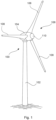
- FIG. 1 shows a schematic representation of a wind turbine according to the invention.
- the wind turbine 100 has a tower 102 and a nacelle 104 on the tower 102.
- An aerodynamic rotor 106 with three rotor blades 108 and a spinner 110 is provided on the nacelle 104.
- the aerodynamic rotor 106 is set in rotation by the wind and thus also rotates an electrodynamic rotor or rotor of a generator, which is directly or indirectly coupled to the aerodynamic rotor 106.
- the electrical generator is arranged in the nacelle 104 and generates electrical energy.
- the pitch angles of the rotor blades 108 can be changed by pitch motors at the rotor blade roots 108b of the respective rotor blades 108.
- Figure 2 shows a manufacturing method for producing a tower segment 1 of a tower 102, for example a tower 102 of a Figure 1 shown wind turbine 100.
- the manufacturing method comprises the steps of providing S1, rolling S2 and bending S3 a plate 1a.
- FIG. 3 shows a schematic block diagram with exemplary method steps of rolling S2.
- Rolling S2 can, in particular, comprise heating S2.1 of plate 1a to a hot rolling temperature, and/or introducing S2.2 at least one transition section Ü, and/or introducing S2.3 at least one constant section K1, K2, K3, K4, K5.
- the rolling method step S2 can comprise further forming and/or heat-treating method steps.
- the introduced thickness profile has a varying thickness dÜ.
- the thickness profile of a transition section Ü preferably has at least two different thicknesses dÜ.
- a constant section K has a substantially constant thickness d1, d2, d3, d4, d5.
- Constant sections K1, K2, K3, K4, K5 that are different from one another can have different constant thicknesses d1, d2, d3, d4, d5. It is conceivable that one or more constant sections have the same thickness.
- Figure 4 shows a schematic block diagram with exemplary method steps of bending S3.
- the method step of bending S3 comprises the steps of heating S3.1 the plate to a hot bending temperature, and/or introducing S3.2 a curvature x1, x2 in the circumferential direction U into the plate 1a, and/or arranging S3.3 at least two plates 1a on top of one another essentially orthogonal to the longitudinal direction L and circumferential direction U of the plates 1a, and/or arranging S3.4 the plate on a mold 40.
- the plate 1a is arranged on a mold 40, which is a lattice mold and/or a mold comprising concrete.
- the introduction S3.2 of a curvature x1, x2 in the circumferential direction U into the plate 1a comprises introducing the curvature by means of plastic hot forming.
- the plate 1a is heated to a hot forming temperature that is above an ambient temperature.
- Figures 5a-5c show a according to the Figure 2 Tower segment 1 produced using the manufacturing process shown.
- the manufacturing method shown provides for the provision of a plate 1a that extends in a longitudinal direction L and orthogonally thereto in a circumferential direction U.
- the plate 1a extends in the longitudinal direction by approximately three to four times as much as in the circumferential direction.
- the planar extent in the longitudinal direction L and circumferential direction U of the plate 1a is many times greater than the thickness of the plate 1a extending orthogonally thereto.
- a thickness profile with varying thickness dÜ is introduced in its longitudinal direction along a longitudinal axis LA.
- a thickness profile that has a first constant section K1 with a first thickness d1 and a second constant section K2 with a second thickness d2.
- the Figures 5a-6 The tower segment 1 shown has a varying thickness profile with a discrete thickness profile; the thickness profile of the first constant section K1 with the thickness d1 transitions abruptly or step-like into the thickness profile of the second constant section K2 with the thickness d2.
- the second constant section K2 was rolled to a thickness d2, which corresponds to approximately one third of the first thickness d1 of the first constant section K1.
- the different thicknesses d1, d2 of the two constant sections K1, K2 are particularly Figures 5b and 5c can be found.
- the second constant section K2 was introduced such that the second constant section K2 is arranged above the first constant section K1 in the longitudinal direction L.
- the two constant sections are arranged essentially parallel to one another.
- the transition between the two constant sections K1, K2 extends across the circumferential direction U perpendicular to it.
- the introduced constant sections K1, K2 have an extension in the longitudinal direction L or a length that is greater than their extension in the circumferential direction U.
- rolling S2 of the provided plate 1a first involves heating S2.1 of the plate to a hot-rolling temperature. This allows the constant sections K1, K2 with the essentially constant thicknesses d1, d2 in the longitudinal direction L and in the circumferential direction U to be subsequently introduced S2.2 with less force.
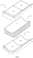
- Figure 6 shows a schematic three-dimensional view of the Figures 5a-5c shown tower segment 1 before and after the bending process step S3 as well as a schematic three-dimensional view of a mold 40 for bending S3 of the tower segment 1. A corresponding bending tool as a counterpart to the mold 40 is not shown.
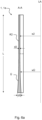
- Figure 5b shows a cross section AA in the longitudinal direction transverse to the circumferential direction of the Figure 5a shown tower segment 1.
- the first constant section K1 with a thickness d1 extends to approximately its middle and starting from approximately the middle of the tower segment 1 to an upper end, the second constant section K2 with a thickness d2.
- This view and the top view of the tower segment 1 in Figure 5c show the curvature x1, x2 in the circumferential direction of the two constant sections K1, K2 of the tower segment 1. From the sectional view AA and the top view of the Figures 5b and 5c It becomes clear that the respective constant sections K1, K2 of the present tower segment 1 have been bent cylindrically.
- the plate 1a In the installed state or operating state of the tower segment 1, the plate 1a has a constant curvature in the circumferential direction with respect to a longitudinal axis LA, depending on the respective constant section. Since the constant sections are essentially bent cylindrically, the constant sections K1, K2 have no curvature in the longitudinal direction in the installed state or operating state.
- bending S3 initially involves heating S3.1 the plate 1a to the hot bending temperature. This allows the plate 1a to be bent S3.2 in the circumferential direction U with less force.
- This hot forming gives the plate a radius or a curvature x1, x2 that is constant in the circumferential direction U, as shown in the Figures 5b , 5c and 6 (lower third) show S3.3.
- the thickness of the transition section decreases continuously up to an upper end of the transition section Ü or approximately up to the middle of the tower segment 1 to a thickness d2 and continuously transitions into the constant section K2 with the constant thickness d2.
- the continuous transition between the transition section Ü and the constant section K2 is shown by the horizontal dashed line in Figure 6a
- the transition section has a curvature that is constant in the circumferential direction and varies in the longitudinal direction of the tower segment 1.
- the Figure 6a The preferred embodiment of a tower segment 1 shown is essentially analogous to that shown in the Figures 5a-6
- the preferred embodiment of the tower segment with the two constant sections shown in the drawing applies in this respect.
- the statements regarding the manufacturing process of the Figures 5a-6 shown tower segments are essentially analogous to those in Figure 6a illustrated preferred embodiment of a tower segment.
- the manufacturing method shown for producing a tower segment 1 of a tower 102 comprises the Figure 7
- the manufacturing process shown additionally comprises the step S4 of producing at least one abutting surface on the plate 1a.
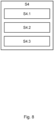
- Figure 8 shows a schematic block diagram with exemplary method steps of generating S4 at least one abutting surface, for example generating S4.1, S4.2 at least one longitudinal abutting surface 3a, 3b and/or at least one circumferential abutting surface 2a, 2b for connecting at least one further plate, and/or generating an abutting surface, removing an edge section S4.3.
- the rolling S2 additionally comprises the introduction S2.3 of a transition section Ü between two constant sections.
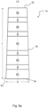
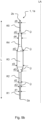
- a tower segment 1 produced with such a manufacturing process is shown in the Figures 9a , 9b and 9c
- a tower segment 1 produced using such a method has, for example, five constant sections K1, K2, K3, K4, K5 arranged parallel to one another in the installed state and above one another in the longitudinal direction, each with constant thicknesses d1, d2, d3, d4, d5. Between these constant sections K1 to K5, transition sections Ü were introduced parallel thereto for a lower notch effect. It may be preferred that a tower segment 1 ends with a transition section Ü at a lower and/or upper end in the installed state.
- Figures 9a , 9b and 9c In the preferred embodiments of a tower segment 1 shown, the respective constant sections K1, K2, K3, K4, K5 arranged parallel to one another have an extension in the longitudinal direction L which is greater than the extension of the transition sections Ü in the longitudinal direction L. In further preferred embodiments, it may be preferred that one or more transition sections Ü have a greater extension in the longitudinal direction L than one or more constant sections of a tower segment 1.
- the tower segment 1 shown shows a thickness profile in which the thickness dÜ of the respective transition section Ü between the adjacent constant sections K1, K2, K3, K4, K5 varies trapezoidally. In particular, the thickness profile varies continuously within the individual transition sections.
- Figure 9b The thickness profile of the tower segment shown has a discrete profile at the transitions between the individual sections.
- Figure 9c shows a thickness profile of a tower segment 1, for example according to Figure 9a , in which the thickness dÜ of the respective transition sections Ü between the adjacent constant sections K1, K2, K3, K4, K5 runs concavely and convexly. In particular, the thickness profile varies continuously within the individual transition sections Ü.
- FIG. 9b The thickness profile of tower segment 1 shown in the figure shows a continuous profile at the transitions between the individual sections.
- Figures 9b and 9c The thickness profiles shown have an increasing thickness in the longitudinal direction L with respect to the installation state or operating state of tower segment 1, starting from a lower end of tower segment 1 via constant section K2 to the middle of tower segment 1, i.e. constant section K3. The thickness of the thickness profile then decreases starting from constant section K3 via constant section K4 to constant section K5, the upper end of tower segment 1.
- the generation S4 of at least one abutment surface comprises the generation S4.1, S4.2 of an upper and lower circumferential abutment surface 2a, 2b and two longitudinal abutment surfaces 3a, 3b.
- the circumferential abutment surfaces 2a, 2b extend in the circumferential direction U essentially on the underside and upper side of the tower segment 1.
- the longitudinal abutment surfaces 3a, 3b extend essentially in the longitudinal direction L, laterally on the tower segment 1.
- the generation of an abutment surface comprises the removal of an edge section S4.3. By removing the edge section S4.3, the Figure 9a The tower segment 1 shown tapers conically in the longitudinal direction L.
- the tower segment 1 produced thereby has a taper in the longitudinal direction, starting from a lower end, the circumferential abutment surface 2a, to an upper end, the circumferential abutment surface 2b.
- the tower segment 1 has, in particular, inclined longitudinal abutment surfaces 3a, 3b.
- Such a tower segment 1 is arranged in the installed state or operating state inclined to a substantially vertically oriented longitudinal axis LA.
- Figure 10 shows a manufacturing method for producing a tower section 10.
- the plates 1a produced as described above are connected to one another at the longitudinal abutment surfaces 3a, 3b S5.
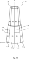
- a tower section 10 produced using this method is shown in Figure 11
- a tower 102 of a wind turbine 100 according to Figure 1 may, for example, comprise a tower section 10 manufactured in this way.
- tower segments were manufactured according to Figure 2 described manufacturing method and additionally edge sections of the plates 1a were removed and circumferential abutment surfaces 2a, 2b on the top and bottom of the plate 1a as well as longitudinal abutment surfaces 3a, 3b in the longitudinal direction of the plate 1a were produced S4.
- edge sections of the plates 1a were removed and circumferential abutment surfaces 2a, 2b on the top and bottom of the plate 1a as well as longitudinal abutment surfaces 3a, 3b in the longitudinal direction of the plate 1a were produced S4.
- eight tower segments 1 were provided and arranged in a ring shape and fixed to one another S5.1.
- a longitudinal welded connection was produced between adjacent plates 1a along the longitudinal abutment surfaces 3a, 3b essentially parallel to the longitudinal axis LA.
- a tower section 10 was produced in which the constant sections K1 of adjacent tower segments 1 and the constant sections K2 of adjacent tower segments 1 have essentially the same constant thicknesses d1, d2.
- the constant sections K1, K2 of such tower segments that are arranged essentially parallel to a main loading direction in the installed state or operating state with a comparatively smaller thickness d1, d2 than the constant sections K1, K2 of such tower segments that are arranged essentially transversely to the main loading direction in the installed state or operating state.
- Figure 12 shows a manufacturing method for producing a tower section 20.
- two or more tower sections are connected S7, welded joints are ground S8, and/or plates in the region of the welded joints are annealed S9.
- the connection S6 of two or more tower sections 10 comprises arranging and fixing S7.1 adjacent tower sections 10 to one another along a circumferential abutting surface and producing S7.2 a circumferential welded joint.
- the grinding S8 comprises grinding the circumferential welded joint S8.1 and/or grinding the longitudinal welded joint S8.2.
- the annealing S9 comprises annealing the plates in the region of the circumferential welded joint S9.1 and/or annealing the longitudinal welded joint S9.2.
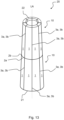
- FIG 13 shows a based on the Figure 12
- a tower 102 of a wind turbine 100 according to Figure 1 may, for example, comprise a tower section 20 manufactured in this way. It may be preferred that a previously described tower section, and/or tower section, and/or tower comprise different tower segments from the manufacturing method according to the invention.
- the production of such a tower section 20 comprises providing two tower sections 10 manufactured as described above. To connect S6 these two tower sections 10, the two tower sections 10 are arranged and fixed S6.1 in the longitudinal direction along the circumferential abutting surfaces 2a, 2b to form a tower section 20 and then a circumferential weld is produced S6.2 between the adjacent tower sections 10 along the circumferential abutting surfaces 2a, 2b. For a longer service life, the circumferential welds are ground S7.1 and annealed S8.1. Furthermore, the tower section 20 is provided with a lower and upper annular flange 21, 22 at its lower end and its upper end.
- the upper ring flange is provided for attaching another tower section 20 or a nacelle 104, and the lower ring flange is provided for attaching another tower section 20 or a foundation.
- the upper and lower ring flanges 21, 22 are designed as screw connections.
Landscapes
- Engineering & Computer Science (AREA)
- Architecture (AREA)
- Chemical & Material Sciences (AREA)
- Life Sciences & Earth Sciences (AREA)
- Mechanical Engineering (AREA)
- Sustainable Development (AREA)
- Combustion & Propulsion (AREA)
- Sustainable Energy (AREA)
- General Engineering & Computer Science (AREA)
- Civil Engineering (AREA)
- Structural Engineering (AREA)
- Materials Engineering (AREA)
- Wood Science & Technology (AREA)
- Power Engineering (AREA)
- Wind Motors (AREA)
Claims (16)
- Procédé de fabrication pour produire un segment de tour (1) d'une tour (102) s'amincissant d'une éolienne (100), dans lequel la tour présente, à l'état monté et à l'état de fonctionnement, un axe longitudinal vertical et une section transversale annulaire orthogonale à cet axe longitudinal, avec les étapes de :- fourniture (S1) d'une plaque (1a) qui s'étend dans une direction longitudinale (L) et orthogonalement à celle-ci dans une direction circonférentielle (U), dans lequel l'extension dans la direction longitudinale (L) est supérieure à l'extension dans la direction circonférentielle (U) ; et- laminage (S2) de la plaque (1a) le long de la direction longitudinale (L) de la plaque (1a), dans lequel le laminage comprend :
l'insertion d'un profil d'épaisseur avec une épaisseur variable (dÜ) ; et- le pliage (S3) de la plaque (1a) dans la direction circonférentielle (U) ; et- la production (S4) d'au moins une surface de jonction sur la plaque (1a) pour relier au moins une autre plaque (1a), dans lequel la production de l'au moins une surface de jonction comprend :la production (S4.1) d'au moins une surface de jonction longitudinale (3a, 3b) pour relier au moins une autre plaque (1a) dans la direction circonférentielle (U) ; etle retrait (S4.3) d'une partie de bord de la plaque (1a) pour régler ou obtenir une inclinaison requise de la tour, de sorte qu'un segment de tour incliné par rapport à l'axe longitudinal à l'état monté dans la direction longitudinale présente une courbure variable. - Procédé de fabrication selon la revendication 1, dans lequel le laminage (S2) comprend :- le chauffage (S2.1) de la plaque à une température de laminage à chaud ; et/ou- l'insertion (S2.2) d'au moins une partie de transition (Ü), dans lequel la partie de transition (Ü) présente une épaisseur variable (dÜ) du profil d'épaisseur inséré ; et/ou- l'insertion (S2.3) d'au moins une partie constante (K1, K2, K3, K4, K5), dans lequel la partie constante (K1, K2, K3, K4, K5) présente une épaisseur constante (d1, d2, d3, d4, d5) du profil d'épaisseur inséré.
- Procédé de fabrication selon l'une quelconque des revendications précédentes, dans lequel le pliage comprend :- le chauffage (S3.1) de la plaque (1a) à une température de pliage à chaud ; et/ou- l'insertion (S3.2) d'une courbure (1,
 2) dans la direction circonférentielle (U) dans la plaque (1a), dans lequel l'insertion de la courbure (1,2)comprend de préférence une insertion de la courbure (1,2) par formage plastique à chaud et/oude préférence une insertion d'une courbure (1,2) constante dans la direction circonférentielle (U) de la plaque (1a) ; et/ou- la disposition (S3.3) l'une sur l'autre d'au moins deux plaques (1a) essentiellement orthogonales à la direction longitudinale (L) et à la direction circonférentielle (U) de la plaque (1a) ; et/ou- la disposition (S3.4) de la plaque (1a) sur un moule (40).
 - Procédé de fabrication selon l'une quelconque des revendications précédentes,- dans lequel l'épaisseur (dÜ) de l'au moins une partie de transition (Ü) varie en continu ou graduellement, et/ou- dans lequel la courbure (1,2) insérée dans la direction circonférentielle (U) varie le long de la direction longitudinale (L) de la plaque (1a).
- Procédé de fabrication selon l'une quelconque des revendications précédentes, avec l'étape de :- production (S4) d'au moins une surface de jonction sur la plaque (1a) pour relier au moins une autre plaque (1a), dans lequel la production de l'au moins une surface de jonction comprend :
la production (S4.2) d'au moins une surface de jonction circonférentielle (2a, 2b) pour relier au moins une autre plaque (1a) dans la direction longitudinale (L). - Procédé de fabrication pour la réalisation d'une partie de tour (10), avec l'étape de :- liaison (S5) de deux plaques (1a) produites selon un procédé de fabrication selon l'une quelconque des revendications précédentes sur les surfaces de jonction longitudinales (3a, 3b) correspondantes, dans lequel la liaison (S5) comprend :la disposition et la fixation (S5.1) de plaques (1a) adjacentes les unes aux autres le long des surfaces de jonction longitudinales (3a, 3b) en une partie de tour (10) annulaire dans la direction circonférentielle (U) ; etla réalisation (S5.2) d'une soudure longitudinale entre les plaques (1a) adjacentes le long des surfaces de jonction longitudinales (3a, 3b).
- Procédé de fabrication pour la réalisation d'une section de tour (20), avec l'étape de :- liaison (S6) de deux parties de tour (10) ou plus produites selon un procédé de fabrication selon la revendication précédente sur les surfaces de jonction circonférentielles (2a, 2b) correspondantes, dans lequel la liaison (S6) comprend :la disposition et la fixation (S6.1) des parties de tour (10) adjacentes les unes aux autres le long des surfaces de jonction circonférentielles (2a, 2b) en une section de tour (20) dans la direction longitudinale (L) ; etla réalisation (S6.2) d'une soudure circonférentielle entre les parties de tour (10) adjacentes le long des surfaces de jonction circonférentielles (2a, 2b).
- Procédé de fabrication selon l'une quelconque des revendications 6 à 7 précédentes, avec l'étape de :- meulage (S7.1) de la soudure circonférentielle et/ou meulage (S7.2) de la soudure longitudinale, et/ou- recuit (S8.1) des plaques dans la zone de la soudure circonférentielle et/ou recuit (S8.2) de la soudure longitudinale.
- Segment de tour (1) d'une tour (102) s'amincissant, en particulier d'une tour (102) s'amincissant d'une éolienne (100), comprenant une plaque (1a), dans lequel la plaque (1a) s'étend dans une direction longitudinale (L) et orthogonalement à celle-ci dans une direction circonférentielle (U), dans lequel l'extension dans la direction longitudinale (L) est supérieure à l'extension dans la direction circonférentielle (U), et dans lequel la plaque (1a) présente un profil d'épaisseur avec une épaisseur variable le long de la direction longitudinale (L) de la plaque (1a), avec- au moins une partie de transition (Ü)avec une épaisseur variable (dÜ) ; et/ou- au moins une partie constante (K1, K2, K3, K4, K5) avec une épaisseur essentiellement constante (d1, d2, d3, d4, d5),
caractérisé en ce que
la courbure (1,2) insérée dans la direction circonférentielle le long de la direction longitudinale (L) de la plaque (1a) à l'état monté varie pour régler ou obtenir une inclinaison requise de la tour. - Partie de tour (10) d'une tour (102), en particulier d'une tour (102) d'une éolienne (100), comprenant deux, trois ou plus segments de tour (1) selon la revendication 9 , dans laquelle- les segments de tour (1) sont disposés de manière annulaire dans la direction circonférentielle (U) ou en tant que sous-partie annulaire et les segments de tour (1) adjacents sont fixés les uns aux autres sur les surfaces de jonction longitudinales (3a, 3b).
- Partie de tour (10) selon la revendication précédente, dans laquelle, à l'état monté, l'épaisseur de la partie de tour est différente dans la direction circonférentielle (U), en particulier entre au moins deux segments de tour (1).
- Section de tour (20) d'une tour (102), en particulier d'une tour (102) d'une éolienne (100), comprenant deux, trois ou plus parties de tour (10) selon l'une quelconque des revendications précédentes 10-11, dans laquelle les parties de tour (10) sont disposées les unes sur les autres à l'état monté dans la direction longitudinale (L) et les parties de tour (10) adjacentes sont fixées les unes aux autres sur les surfaces de jonction circonférentielles (2a, 2b).
- Section de tour (20) selon la revendication précédente, dans laquelle la section de tour (20)- présente, sur une extrémité supérieure dans la direction longitudinale (L) à l'état monté, une bride annulaire supérieure (22) pour la fixation d'une autre section de tour ou nacelle (104), et/ou- présente, sur une extrémité inférieure dans la direction longitudinale (L) à l'état monté, une bride annulaire inférieure (21) pour la fixation d'une autre section de tour (20) ou d'une base.
- Tour (102) comprenant une section de tour (20) selon l'une quelconque des revendications 12-13 précédentes.
- Éolienne (100) comprenant une tour (102) selon la revendication précédente.
- Utilisation d'un segment de tour selon la revendication 9 et/ou d'une partie de tour selon l'une quelconque des revendications précédentes 10-11 et/ou d'une section de tour selon l'une quelconque des revendications précédentes 12-13 pour une tour, en particulier pour une tour pour une éolienne.
Applications Claiming Priority (2)
| Application Number | Priority Date | Filing Date | Title |
|---|---|---|---|
| DE102019120175.6A DE102019120175A1 (de) | 2019-07-25 | 2019-07-25 | Verfahren zum Erzeugen eines Turmsegments und Turmsegment |
| PCT/EP2020/070696 WO2021013894A1 (fr) | 2019-07-25 | 2020-07-22 | Procédé de production d'un segment de tour et segment de tour |
Publications (3)
| Publication Number | Publication Date |
|---|---|
| EP4004310A1 EP4004310A1 (fr) | 2022-06-01 |
| EP4004310B1 true EP4004310B1 (fr) | 2025-04-23 |
| EP4004310C0 EP4004310C0 (fr) | 2025-04-23 |
Family
ID=71784054
Family Applications (1)
| Application Number | Title | Priority Date | Filing Date |
|---|---|---|---|
| EP20745178.2A Active EP4004310B1 (fr) | 2019-07-25 | 2020-07-22 | Procédé de production d'un segment de tour et segment de tour |
Country Status (4)
| Country | Link |
|---|---|
| US (1) | US20220280990A1 (fr) |
| EP (1) | EP4004310B1 (fr) |
| DE (1) | DE102019120175A1 (fr) |
| WO (1) | WO2021013894A1 (fr) |
Families Citing this family (4)
| Publication number | Priority date | Publication date | Assignee | Title |
|---|---|---|---|---|
| GB2584724B (en) * | 2019-06-14 | 2023-09-20 | Balfour Beatty Plc | Modular tube and method of manufacturing |
| CN114393069A (zh) * | 2021-12-29 | 2022-04-26 | 东北大学无锡研究院 | 一种用于制取变壁厚风塔的成型压力机 |
| US12529239B2 (en) * | 2022-10-31 | 2026-01-20 | Ge Infrastructure Technology Llc | Wind turbine tower structure with stacked tower sections |
| DE102023109827A1 (de) * | 2023-04-19 | 2024-10-24 | Haeusler Holding Ag | Konusförmiges Biegen eines Blechs |
Family Cites Families (3)
| Publication number | Priority date | Publication date | Assignee | Title |
|---|---|---|---|---|
| JP2005264535A (ja) | 2004-03-18 | 2005-09-29 | Jfe Steel Kk | 厚肉部を有する円形鋼管柱およびその製造方法 |
| ATE471453T1 (de) * | 2004-11-10 | 2010-07-15 | Vestas Wind Sys As | Turmteil für eine windturbine, verfahren zur herstellung eines turmteils und verwendungen davon |
| JP5146580B2 (ja) * | 2010-09-09 | 2013-02-20 | Jfeスチール株式会社 | 鋼管柱構造物及びその製造方法 |
-
2019
- 2019-07-25 DE DE102019120175.6A patent/DE102019120175A1/de not_active Withdrawn
-
2020
- 2020-07-22 WO PCT/EP2020/070696 patent/WO2021013894A1/fr not_active Ceased
- 2020-07-22 EP EP20745178.2A patent/EP4004310B1/fr active Active
- 2020-07-22 US US17/630,096 patent/US20220280990A1/en not_active Abandoned
Also Published As
| Publication number | Publication date |
|---|---|
| US20220280990A1 (en) | 2022-09-08 |
| DE102019120175A1 (de) | 2021-01-28 |
| EP4004310A1 (fr) | 2022-06-01 |
| EP4004310C0 (fr) | 2025-04-23 |
| WO2021013894A1 (fr) | 2021-01-28 |
Similar Documents
| Publication | Publication Date | Title |
|---|---|---|
| EP4004310B1 (fr) | Procédé de production d'un segment de tour et segment de tour | |
| EP2082131B2 (fr) | Mât pour éolienne | |
| DE102011050966B4 (de) | Blattbefestigungskonfiguration für eine Windkraftanlage mit abgeflachten Bolzen | |
| EP3701107B1 (fr) | Console annulaire destinée à la contrainte externe d'un segment de tour, système de contrainte externe d'une tour hybride, section de tour d'une tour hybride, tour hybride, éolienne et procédé de montage d'un système de contrainte externe pour une tour hybride | |
| EP3330530B1 (fr) | Pale d'éolienne | |
| EP3497325B1 (fr) | Segment de mât, partie de mât, mât, éolienne ainsi que procédé permettant de fabriquer un segment de mât et de relier des segments de mât | |
| EP2882962B1 (fr) | Arbre de rotor destiné à une turbine éolienne | |
| EP3855014B1 (fr) | Pale de rotor divisée d'une éolienne ainsi que segment de pale de rotor | |
| DE102007018025A1 (de) | Windenergieanlagenturm | |
| EP3491239B1 (fr) | Élément de raccordement permettant de raccorder des sections de tour, section de tour, tour, éolienne ainsi que procédé de fabrication d'une section de tour et de raccordement de sections de tour | |
| EP3927918B1 (fr) | Composant d'éolienne pour une tour d'éolienne, tour d'éolienne, pale de rotor, éolienne et procédé de fabrication d'un composant d'éolienne | |
| EP3701143B1 (fr) | Pale de rotor d'une éolienne et procédé de conception de celle-ci | |
| DE202009015675U1 (de) | Turmsegment, wie auch ein Blechzuschnitt für ein Turmsegment | |
| EP3601791B1 (fr) | Segment bride pour un segment annulaire de tour en acier pour éolienne et procédé associé | |
| EP3559417B1 (fr) | Procédé de fabrication d'une pale de rotor d'éolienne et pale de rotor d'éolienne | |
| DE102017120487A1 (de) | Turm einer Windenergieanlage und Verfahren zum Herstellen eines Sektionssegments für einen solchen Turm | |
| EP2116675B1 (fr) | Tour pour une éolienne avec partie de bride pour connection de segments | |
| EP3658770B1 (fr) | Segment annulaire de tour en acier pour éoliennes et procédé | |
| EP3956561B1 (fr) | Section de tour et procédé pour la construction d'une tour | |
| DE102020204447B4 (de) | Verfahren zur Herstellung eines Bauteils für eine Windenergieanlage | |
| EP3927966B1 (fr) | Segment annulaire de tour en acier pour une partie de tour d'éolienne et procédé | |
| EP4723473A1 (fr) | Installation photovoltaïque à structure porteuse améliorée |
Legal Events
| Date | Code | Title | Description |
|---|---|---|---|
| STAA | Information on the status of an ep patent application or granted ep patent |
Free format text: STATUS: UNKNOWN |
|
| STAA | Information on the status of an ep patent application or granted ep patent |
Free format text: STATUS: THE INTERNATIONAL PUBLICATION HAS BEEN MADE |
|
| PUAI | Public reference made under article 153(3) epc to a published international application that has entered the european phase |
Free format text: ORIGINAL CODE: 0009012 |
|
| STAA | Information on the status of an ep patent application or granted ep patent |
Free format text: STATUS: REQUEST FOR EXAMINATION WAS MADE |
|
| 17P | Request for examination filed |
Effective date: 20220225 |
|
| AK | Designated contracting states |
Kind code of ref document: A1 Designated state(s): AL AT BE BG CH CY CZ DE DK EE ES FI FR GB GR HR HU IE IS IT LI LT LU LV MC MK MT NL NO PL PT RO RS SE SI SK SM TR |
|
| DAV | Request for validation of the european patent (deleted) | ||
| DAX | Request for extension of the european patent (deleted) | ||
| GRAP | Despatch of communication of intention to grant a patent |
Free format text: ORIGINAL CODE: EPIDOSNIGR1 |
|
| STAA | Information on the status of an ep patent application or granted ep patent |
Free format text: STATUS: GRANT OF PATENT IS INTENDED |
|
| INTG | Intention to grant announced |
Effective date: 20240729 |
|
| GRAJ | Information related to disapproval of communication of intention to grant by the applicant or resumption of examination proceedings by the epo deleted |
Free format text: ORIGINAL CODE: EPIDOSDIGR1 |
|
| STAA | Information on the status of an ep patent application or granted ep patent |
Free format text: STATUS: REQUEST FOR EXAMINATION WAS MADE |
|
| INTC | Intention to grant announced (deleted) | ||
| GRAP | Despatch of communication of intention to grant a patent |
Free format text: ORIGINAL CODE: EPIDOSNIGR1 |
|
| STAA | Information on the status of an ep patent application or granted ep patent |
Free format text: STATUS: GRANT OF PATENT IS INTENDED |
|
| INTG | Intention to grant announced |
Effective date: 20241210 |
|
| GRAS | Grant fee paid |
Free format text: ORIGINAL CODE: EPIDOSNIGR3 |
|
| GRAA | (expected) grant |
Free format text: ORIGINAL CODE: 0009210 |
|
| STAA | Information on the status of an ep patent application or granted ep patent |
Free format text: STATUS: THE PATENT HAS BEEN GRANTED |
|
| AK | Designated contracting states |
Kind code of ref document: B1 Designated state(s): AL AT BE BG CH CY CZ DE DK EE ES FI FR GB GR HR HU IE IS IT LI LT LU LV MC MK MT NL NO PL PT RO RS SE SI SK SM TR |
|
| REG | Reference to a national code |
Ref country code: GB Ref legal event code: FG4D Free format text: NOT ENGLISH |
|
| REG | Reference to a national code |
Ref country code: CH Ref legal event code: EP |
|
| REG | Reference to a national code |
Ref country code: IE Ref legal event code: FG4D Free format text: LANGUAGE OF EP DOCUMENT: GERMAN |
|
| U01 | Request for unitary effect filed |
Effective date: 20250423 |
|
| U07 | Unitary effect registered |
Designated state(s): AT BE BG DE DK EE FI FR IT LT LU LV MT NL PT RO SE SI Effective date: 20250428 |
|
| U20 | Renewal fee for the european patent with unitary effect paid |
Year of fee payment: 6 Effective date: 20250630 |
|
| PG25 | Lapsed in a contracting state [announced via postgrant information from national office to epo] |
Ref country code: ES Free format text: LAPSE BECAUSE OF FAILURE TO SUBMIT A TRANSLATION OF THE DESCRIPTION OR TO PAY THE FEE WITHIN THE PRESCRIBED TIME-LIMIT Effective date: 20250423 |
|
| PG25 | Lapsed in a contracting state [announced via postgrant information from national office to epo] |
Ref country code: NO Free format text: LAPSE BECAUSE OF FAILURE TO SUBMIT A TRANSLATION OF THE DESCRIPTION OR TO PAY THE FEE WITHIN THE PRESCRIBED TIME-LIMIT Effective date: 20250723 Ref country code: GR Free format text: LAPSE BECAUSE OF FAILURE TO SUBMIT A TRANSLATION OF THE DESCRIPTION OR TO PAY THE FEE WITHIN THE PRESCRIBED TIME-LIMIT Effective date: 20250724 |
|
| PG25 | Lapsed in a contracting state [announced via postgrant information from national office to epo] |
Ref country code: PL Free format text: LAPSE BECAUSE OF FAILURE TO SUBMIT A TRANSLATION OF THE DESCRIPTION OR TO PAY THE FEE WITHIN THE PRESCRIBED TIME-LIMIT Effective date: 20250423 |
|
| PG25 | Lapsed in a contracting state [announced via postgrant information from national office to epo] |
Ref country code: HR Free format text: LAPSE BECAUSE OF FAILURE TO SUBMIT A TRANSLATION OF THE DESCRIPTION OR TO PAY THE FEE WITHIN THE PRESCRIBED TIME-LIMIT Effective date: 20250423 |
|
| PG25 | Lapsed in a contracting state [announced via postgrant information from national office to epo] |
Ref country code: RS Free format text: LAPSE BECAUSE OF FAILURE TO SUBMIT A TRANSLATION OF THE DESCRIPTION OR TO PAY THE FEE WITHIN THE PRESCRIBED TIME-LIMIT Effective date: 20250723 |
|
| PG25 | Lapsed in a contracting state [announced via postgrant information from national office to epo] |
Ref country code: IS Free format text: LAPSE BECAUSE OF FAILURE TO SUBMIT A TRANSLATION OF THE DESCRIPTION OR TO PAY THE FEE WITHIN THE PRESCRIBED TIME-LIMIT Effective date: 20250823 |
|
| PG25 | Lapsed in a contracting state [announced via postgrant information from national office to epo] |
Ref country code: SM Free format text: LAPSE BECAUSE OF FAILURE TO SUBMIT A TRANSLATION OF THE DESCRIPTION OR TO PAY THE FEE WITHIN THE PRESCRIBED TIME-LIMIT Effective date: 20250423 |
|
| PG25 | Lapsed in a contracting state [announced via postgrant information from national office to epo] |
Ref country code: CZ Free format text: LAPSE BECAUSE OF FAILURE TO SUBMIT A TRANSLATION OF THE DESCRIPTION OR TO PAY THE FEE WITHIN THE PRESCRIBED TIME-LIMIT Effective date: 20250423 |
|
| PG25 | Lapsed in a contracting state [announced via postgrant information from national office to epo] |
Ref country code: SK Free format text: LAPSE BECAUSE OF FAILURE TO SUBMIT A TRANSLATION OF THE DESCRIPTION OR TO PAY THE FEE WITHIN THE PRESCRIBED TIME-LIMIT Effective date: 20250423 |
|
| REG | Reference to a national code |
Ref country code: CH Ref legal event code: H13 Free format text: ST27 STATUS EVENT CODE: U-0-0-H10-H13 (AS PROVIDED BY THE NATIONAL OFFICE) Effective date: 20260224 |
|
| PLBE | No opposition filed within time limit |
Free format text: ORIGINAL CODE: 0009261 |
|
| STAA | Information on the status of an ep patent application or granted ep patent |
Free format text: STATUS: NO OPPOSITION FILED WITHIN TIME LIMIT |
|
| REG | Reference to a national code |
Ref country code: CH Ref legal event code: L10 Free format text: ST27 STATUS EVENT CODE: U-0-0-L10-L00 (AS PROVIDED BY THE NATIONAL OFFICE) Effective date: 20260304 |
|
| GBPC | Gb: european patent ceased through non-payment of renewal fee |
Effective date: 20250723 |
|
| 26N | No opposition filed |
Effective date: 20260126 |
|
| PG25 | Lapsed in a contracting state [announced via postgrant information from national office to epo] |
Ref country code: GB Free format text: LAPSE BECAUSE OF NON-PAYMENT OF DUE FEES Effective date: 20250723 |
|
| PG25 | Lapsed in a contracting state [announced via postgrant information from national office to epo] |
Ref country code: CH Free format text: LAPSE BECAUSE OF NON-PAYMENT OF DUE FEES Effective date: 20250731 |