EP4004316B1 - Ensemble raccord pour un ouvrant qui peut être éloigné en parallèle et ensemble fermeture pour une ouverture de bâtiment - Google Patents
Ensemble raccord pour un ouvrant qui peut être éloigné en parallèle et ensemble fermeture pour une ouverture de bâtiment Download PDFInfo
- Publication number
- EP4004316B1 EP4004316B1 EP20746644.2A EP20746644A EP4004316B1 EP 4004316 B1 EP4004316 B1 EP 4004316B1 EP 20746644 A EP20746644 A EP 20746644A EP 4004316 B1 EP4004316 B1 EP 4004316B1
- Authority
- EP
- European Patent Office
- Prior art keywords
- movement
- unit
- spring
- storage device
- energy storage
- Prior art date
- Legal status (The legal status is an assumption and is not a legal conclusion. Google has not performed a legal analysis and makes no representation as to the accuracy of the status listed.)
- Active
Links
Images




Classifications
-
- E—FIXED CONSTRUCTIONS
- E05—LOCKS; KEYS; WINDOW OR DOOR FITTINGS; SAFES
- E05D—HINGES OR SUSPENSION DEVICES FOR DOORS, WINDOWS OR WINGS
- E05D15/00—Suspension arrangements for wings
- E05D15/06—Suspension arrangements for wings for wings sliding horizontally more or less in their own plane
- E05D15/10—Suspension arrangements for wings for wings sliding horizontally more or less in their own plane movable out of one plane into a second parallel plane
-
- E—FIXED CONSTRUCTIONS
- E05—LOCKS; KEYS; WINDOW OR DOOR FITTINGS; SAFES
- E05F—DEVICES FOR MOVING WINGS INTO OPEN OR CLOSED POSITION; CHECKS FOR WINGS; WING FITTINGS NOT OTHERWISE PROVIDED FOR, CONCERNED WITH THE FUNCTIONING OF THE WING
- E05F1/00—Closers or openers for wings, not otherwise provided for in this subclass
- E05F1/08—Closers or openers for wings, not otherwise provided for in this subclass spring-actuated, e.g. for horizontally sliding wings
- E05F1/16—Closers or openers for wings, not otherwise provided for in this subclass spring-actuated, e.g. for horizontally sliding wings for sliding wings
-
- E—FIXED CONSTRUCTIONS
- E05—LOCKS; KEYS; WINDOW OR DOOR FITTINGS; SAFES
- E05F—DEVICES FOR MOVING WINGS INTO OPEN OR CLOSED POSITION; CHECKS FOR WINGS; WING FITTINGS NOT OTHERWISE PROVIDED FOR, CONCERNED WITH THE FUNCTIONING OF THE WING
- E05F5/00—Braking devices, e.g. checks; Stops; Buffers
- E05F5/003—Braking devices, e.g. checks; Stops; Buffers for sliding wings
-
- E—FIXED CONSTRUCTIONS
- E06—DOORS, WINDOWS, SHUTTERS, OR ROLLER BLINDS IN GENERAL; LADDERS
- E06B—FIXED OR MOVABLE CLOSURES FOR OPENINGS IN BUILDINGS, VEHICLES, FENCES OR LIKE ENCLOSURES IN GENERAL, e.g. DOORS, WINDOWS, BLINDS, GATES
- E06B3/00—Window sashes, door leaves, or like elements for closing wall or like openings; Layout of fixed or moving closures, e.g. windows in wall or like openings; Features of rigidly-mounted outer frames relating to the mounting of wing frames
- E06B3/32—Arrangements of wings characterised by the manner of movement; Arrangements of movable wings in openings; Features of wings or frames relating solely to the manner of movement of the wing
- E06B3/50—Arrangements of wings characterised by the manner of movement; Arrangements of movable wings in openings; Features of wings or frames relating solely to the manner of movement of the wing with more than one kind of movement
-
- E—FIXED CONSTRUCTIONS
- E05—LOCKS; KEYS; WINDOW OR DOOR FITTINGS; SAFES
- E05D—HINGES OR SUSPENSION DEVICES FOR DOORS, WINDOWS OR WINGS
- E05D15/00—Suspension arrangements for wings
- E05D15/06—Suspension arrangements for wings for wings sliding horizontally more or less in their own plane
- E05D15/10—Suspension arrangements for wings for wings sliding horizontally more or less in their own plane movable out of one plane into a second parallel plane
- E05D2015/1028—Suspension arrangements for wings for wings sliding horizontally more or less in their own plane movable out of one plane into a second parallel plane with only the wing moving transversely
-
- E—FIXED CONSTRUCTIONS
- E05—LOCKS; KEYS; WINDOW OR DOOR FITTINGS; SAFES
- E05Y—INDEXING SCHEME ASSOCIATED WITH SUBCLASSES E05D AND E05F, RELATING TO CONSTRUCTION ELEMENTS, ELECTRIC CONTROL, POWER SUPPLY, POWER SIGNAL OR TRANSMISSION, USER INTERFACES, MOUNTING OR COUPLING, DETAILS, ACCESSORIES, AUXILIARY OPERATIONS NOT OTHERWISE PROVIDED FOR, APPLICATION THEREOF
- E05Y2201/00—Constructional elements; Accessories therefor
- E05Y2201/20—Brakes; Disengaging means; Holders; Stops; Valves; Accessories therefor
- E05Y2201/21—Brakes
-
- E—FIXED CONSTRUCTIONS
- E05—LOCKS; KEYS; WINDOW OR DOOR FITTINGS; SAFES
- E05Y—INDEXING SCHEME ASSOCIATED WITH SUBCLASSES E05D AND E05F, RELATING TO CONSTRUCTION ELEMENTS, ELECTRIC CONTROL, POWER SUPPLY, POWER SIGNAL OR TRANSMISSION, USER INTERFACES, MOUNTING OR COUPLING, DETAILS, ACCESSORIES, AUXILIARY OPERATIONS NOT OTHERWISE PROVIDED FOR, APPLICATION THEREOF
- E05Y2201/00—Constructional elements; Accessories therefor
- E05Y2201/40—Motors; Magnets; Springs; Weights; Accessories therefor
- E05Y2201/404—Function thereof
- E05Y2201/41—Function thereof for closing
- E05Y2201/412—Function thereof for closing for the final closing movement
-
- E—FIXED CONSTRUCTIONS
- E05—LOCKS; KEYS; WINDOW OR DOOR FITTINGS; SAFES
- E05Y—INDEXING SCHEME ASSOCIATED WITH SUBCLASSES E05D AND E05F, RELATING TO CONSTRUCTION ELEMENTS, ELECTRIC CONTROL, POWER SUPPLY, POWER SIGNAL OR TRANSMISSION, USER INTERFACES, MOUNTING OR COUPLING, DETAILS, ACCESSORIES, AUXILIARY OPERATIONS NOT OTHERWISE PROVIDED FOR, APPLICATION THEREOF
- E05Y2201/00—Constructional elements; Accessories therefor
- E05Y2201/60—Suspension or transmission members; Accessories therefor
- E05Y2201/622—Suspension or transmission members elements
- E05Y2201/64—Carriers
-
- E—FIXED CONSTRUCTIONS
- E05—LOCKS; KEYS; WINDOW OR DOOR FITTINGS; SAFES
- E05Y—INDEXING SCHEME ASSOCIATED WITH SUBCLASSES E05D AND E05F, RELATING TO CONSTRUCTION ELEMENTS, ELECTRIC CONTROL, POWER SUPPLY, POWER SIGNAL OR TRANSMISSION, USER INTERFACES, MOUNTING OR COUPLING, DETAILS, ACCESSORIES, AUXILIARY OPERATIONS NOT OTHERWISE PROVIDED FOR, APPLICATION THEREOF
- E05Y2900/00—Application of doors, windows, wings or fittings thereof
- E05Y2900/10—Application of doors, windows, wings or fittings thereof for buildings or parts thereof
- E05Y2900/13—Type of wing
- E05Y2900/132—Doors
-
- E—FIXED CONSTRUCTIONS
- E05—LOCKS; KEYS; WINDOW OR DOOR FITTINGS; SAFES
- E05Y—INDEXING SCHEME ASSOCIATED WITH SUBCLASSES E05D AND E05F, RELATING TO CONSTRUCTION ELEMENTS, ELECTRIC CONTROL, POWER SUPPLY, POWER SIGNAL OR TRANSMISSION, USER INTERFACES, MOUNTING OR COUPLING, DETAILS, ACCESSORIES, AUXILIARY OPERATIONS NOT OTHERWISE PROVIDED FOR, APPLICATION THEREOF
- E05Y2900/00—Application of doors, windows, wings or fittings thereof
- E05Y2900/10—Application of doors, windows, wings or fittings thereof for buildings or parts thereof
- E05Y2900/13—Type of wing
- E05Y2900/148—Windows
Definitions
- the invention relates to a fitting arrangement for a parallel-positionable sash of a sliding window or a sliding door, comprising a control unit with a mounting part for fixing to the sash and a display part that can be moved relative to the mounting part for parallel positioning of the sash and a movement unit with an energy storage device that is attached to the control unit.
- the invention further relates to a locking arrangement, in particular a sliding window or a sliding door, for a building opening, comprising a frame, a control unit with a mounting part fixed to the sash and a display part that can be moved relative to the mounting part, a sash that can be moved in a closed position by means of the
- the control unit can be brought close to the frame and positioned parallel to the frame so that it can be moved along a guide rail of the frame.
- a generic fitting arrangement and a generic locking arrangement are made of CN 202831939 U known.
- Sliding windows or sliding doors are often designed with a sash that can be opened parallel to a frame.
- the sash can be placed or pressed against the frame to close the window or door. To open the sash, it is removed from the frame, while the frame and sash remain parallel. In this parallel position, the sash can be moved to create a window or door opening. In comparison to sliding windows or sliding doors, where the sash is lifted to open, sliding windows and sliding doors with a sash that can be opened parallel can be sealed more effectively.
- the sash is first moved along the frame to an end position and then moved towards the frame and pressed against it to form a seal.
- the end position is typically defined by a stop between the frame and the sash. Particularly with heavy sashes and/or when operated with force, it can happen that the sash bounces back from the stop so that the sash cannot be closed. When the sash bounces back, large forces are also exerted, which can lead to long-term damage to the sliding window or sliding door or its anchoring to a building.
- a lifting-sliding door is known, the leaf of which is lifted upwards to open.
- the known lifting-sliding door comprises a groove on an upper front side facing a frame, in which a housing of a retraction device is mounted.
- a The driver is mounted so that it can be moved and can be coupled to a projection on a holder in order to brake the sliding door when it moves into an end position.
- the holder is fixed to an adapter profile on the frame above the retraction device.
- the driver is fixed to a piston rod in a damping direction and can be moved in a direction perpendicular to the damping direction.
- WO 2012/095831 A1 discloses a soft-closing fitting for a sliding sash or a tilt-sliding sash for the controlled movement of the sash from a parked position to a closed position.
- Two movement elements are movable in the longitudinal direction. A longitudinal movement of the sash is thus possible.
- the two movement elements are connected to a connecting rod, which keeps them at a fixed distance from each other and allows them to move together.
- a projection arm is pivotally attached to each of the two movement elements.
- a parking catch keeps the arms in a raised position during movement of the fitting over the movement elements.
- the parallel adjustable wing according to EN 10 2016 225 385 A1 is guided on the top of the frame by control units with guide rollers. There is therefore not enough space for conventional retraction devices.
- the movement unit supports a closing movement of the wing.
- a fitting arrangement for a piece of furniture is known.
- a setting-down movement is caused by the movement of guide rollers of a wing along a curved section of a guide rail.
- the setting-down movement is supported by a movement unit arranged on the furniture body.
- a fitting arrangement for a parallel-opening sash of a sliding window or sliding door.
- the fitting arrangement serves to connect the sash to a frame, which is typically fixed to the building.
- the fitting arrangement has a control unit with a mounting part for fixing to the sash and a display part that can be moved relative to the mounting part for parallel parking of the sash.
- the display part can be moved using a guide rail.
- the control unit makes it possible to park the sash away from the frame or to move it towards the frame so that it rests against the frame.
- the orientation of the sash relative to the frame otherwise typically remains unchanged.
- the sash extends parallel to the frame or the sash in the position resting against the frame.
- the parking movement can run perpendicular to an extension plane of the sash.
- the fitting arrangement can have a further control unit.
- the fitting arrangement can also enable the sash to be tilted relative to the frame.
- the mounting part When the fitting arrangement is mounted, the mounting part is firmly connected to the sash and cannot move relative to it.
- the opening part is movable relative to the mounting part and therefore relative to the sash, in particular perpendicular to an extension plane of the sash.
- the opening part When installed, it is typically guided in a guide rail along the frame.
- Directional information such as sideways or above refers to the assembled state of the fitting arrangement or the locking arrangement, i.e. their installation position.
- the fitting arrangement further comprises a movement unit which is fastened to the control unit and which comprises an energy storage device and an activation element for the energy storage device.
- a component of the movement unit can be fastened to the control unit in a detachable or non-detachable manner.
- a component of the movement unit can be held immovably in at least one spatial direction, preferably in all spatial directions, on a component of the control unit, in particular the display part.
- the movement unit serves to brake the sash and/or to support a movement, preferably to move the sash automatically, along a guide rail of a frame.
- the movement unit makes it easier to move the sash, i.e. it simplifies operation and increases ease of use.
- the fitting arrangement By braking the sash, it can be avoided that it hits the frame hard. This helps to avoid damage and facilitates subsequent targeted movement of the sash, in particular supported or caused by the movement unit.
- the fitting arrangement By attaching the movement unit to the control unit, the fitting arrangement has a compact design.
- the frame and a sash spar can therefore be designed to be slim, which is often desired, particularly for aesthetic reasons.
- the compact design means that the fitting arrangement can be designed to be compatible with existing profiles for frames and/or sash spars.
- the fitting arrangement with the movement unit can therefore be used with existing frames and sash spars for which such movement support was not previously available.
- the energy storage device can store the energy required to support the movement and make it available when needed.
- the energy can typically be stored in the form of potential mechanical energy in the energy storage device.
- the energy storage device can have a dissipative effect.
- the sash can be slowed down by means of the fitting arrangement through energy dissipation.
- the energy supplied to the energy storage device is not stored in the energy storage device at least in part in one direction of movement of the sash. Instead, part of the energy supplied is dissipated in the energy storage device and can be released in the form of heat.
- the activation element can interact with the energy storage device, in particular to supply energy to it or to discharge energy from it.
- the activation element advantageously also serves to trigger the release of energy from the energy storage device.
- the activation element typically interacts with a driver of the energy storage device.
- the activation element can be designed as a pin, a sheet metal part or a projection.
- the driver can overlap the activation element on two opposite sides, in particular with one prong each, when the activation element interacts with the energy storage device.
- the fitting arrangement according to the invention can be part of a locking arrangement according to the invention described here.
- the energy storage device is firmly connected to the opening part. This enables a particularly compact design of the fitting arrangement.
- the activation element is Design typically mounted on the guide rail of the frame.
- the activation element is firmly connected to the display part.
- the activation element typically extends in a vertical direction when installed.
- a driver of the energy storage device is typically arranged on the side of the energy storage device when installed. In this embodiment, height adjustment to compensate for manufacturing and installation tolerances can be dispensed with.
- the energy storage device is typically mounted on the frame, in particular its guide rail.
- the energy storage device has a body and a spring-damper unit that is arranged in the body.
- the body forms an interface for receiving the spring-damper unit.
- the body can be easily attached to the control unit or, if necessary, to the frame.
- the body can be rigid. Alternatively, the body can have two parts that move relative to one another.
- a spring element of the spring-damper unit serves to store and release potential energy to support the movement of a sash with the fitting arrangement.
- a damper element of the spring-damper unit serves to dissipate mechanical energy, i.e. convert it into heat. The damping can set up a gentle movement of the sash. In particular, a hard impact of the sash on the frame can be prevented.
- the spring-damper unit is preferably designed with a gas spring and/or an oil damper. Such a spring-damper unit can be designed and arranged in a particularly space-saving manner.
- the energy storage device has a driver for the activation element, which can be locked to the body in a tensioned position of the spring-damper unit. By locking, the Spring-damper unit held in the tensioned position. In the tensioned position, more potential energy is stored in a spring element of the spring-damper unit than in a relaxed position.
- the driver is generally coupled to the spring-damper unit, in particular arranged on a piston rod of the spring-damper unit. The driver can preferably be released from the locking mechanism by the activation element. The energy storage device can then release the stored energy, in particular with the driver being supported on the activation element.
- the spring-damper unit can be connected to the driver via a coupling rod. This can simplify the arrangement of the spring-damper unit and the driver on different sides of the display part, especially if the body is rigid and the spring-damper unit has a compression spring.
- the coupling rod can extend in a straight line. A straight coupling rod is particularly stable and can be manufactured inexpensively.
- the coupling rod can extend through a recess in the display part. The recess enables the coupling rod to be guided from one side of the display part to the other in a space-saving manner.
- the spring-damper unit can be connected to the body at one end, preferably in an articulated manner.
- An articulated connection can simplify the assembly of the spring-damper unit by first establishing the articulated connection and then pivoting the other end of the spring-damper unit into the body.
- the spring-damper unit can have a slide at the other end, which is slidably guided on the body.
- the slide is preferably guided on the body in two planes. This can reliably prevent the slide from tipping over. It can be provided that the coupling rod engages (is articulated on) the slide. This can simplify the assembly of the coupling rod.
- the coupling rod has one or more tapered or thickened portions at its slide-side end, which can be inserted into a corresponding slot in the slide, wherein the After insertion, the coupling rod can be fixed to the slide by axial displacement until it rests against an axial stop.
- the movement unit can have a compression spring.
- a compression spring can be stronger than a tension spring in the same space.
- the embodiment with a compression spring is particularly suitable for an activation element arranged to the side of the energy storage device.
- the compression spring can be coupled to the driver via a deflection mechanism.
- a driver of the movement unit can be arranged on this side or the other side of the control unit and/or a guide roller, as seen from a spring element of the movement unit.
- the movement unit can be provided with a tension spring.
- This embodiment is particularly suitable for an activation element arranged above the energy storage device.
- a driver of the movement unit is typically arranged - as seen from a spring element of the movement unit - beyond the control unit and/or a guide roller.
- the movement unit can be locked to the display part. This enables quick assembly and can ensure reliable fixation.
- the locking mechanism can be set up for variable positioning of the movement unit on the display part. This allows for easy adaptability, for example to different sash widths.
- the movement unit can be screwed or riveted to the display part. This can create a particularly stable connection.
- the body and the display part are formed in one piece with one another, for example as a common bent-stamped part. A body of the movement unit is preferably connected to the display part in the aforementioned manner.
- the fitting arrangement advantageously also has at least one guide roller, preferably two guide rollers.
- the fitting arrangement can be guided on a guide rail of the frame in the assembled state via the guide rollers.
- the guide roller(s) can also ensure the correct alignment of the activation element relative to the energy storage device, in particular to a driver of the energy storage device.
- the guide roller(s) can be arranged on a body of the energy storage device and/or on the display part.
- the scope of the present invention also includes a locking arrangement for a building opening.
- the locking arrangement can in particular be designed as a sliding window or a sliding door.
- the closure arrangement has a cover frame.
- the cover frame is intended for installation fixed to the building. When installed, the cover frame is typically arranged all the way around the building opening.
- the building opening is typically formed in an external wall of a building. Alternatively, the building opening can be formed in an internal wall of the building.
- the locking arrangement further comprises a control unit with a mounting part fixed to the sash and a projection part that can be moved relative to the mounting part.
- the locking arrangement further comprises a sash.
- the mounting part is fixedly connected to the sash and cannot move relative to it.
- the projection part can be moved relative to the mounting part and thus the sash, in particular perpendicular to an extension plane of the sash.
- the control unit is typically arranged at the top of the sash, in particular on an upper, horizontally extending sash spar.
- the sash and the frame usually extend in a vertical plane when assembled.
- the sash In a closed position, the sash can be brought close to the frame using the control unit and can be parked parallel to the frame. In the parked position, the sash can be moved along a guide rail of the frame. Bringing it close and parking it is typically only possible in the closed position.
- the closed position usually corresponds to an end position of the sash relative to the frame, beyond which the sash cannot be moved.
- the opening part In order to be able to move the sash along the guide rail in the parked position, the opening part is guided using the guide rail.
- the locking arrangement can have a non-openable fixed field and/or another openable sash. In the closed position, the sash typically completely covers the building opening or the openable and closable section of the building opening assigned to the sash.
- the locking arrangement can also be designed to tilt the sash relative to the frame.
- the sash When the sash is in the closed position, it can be moved away from the frame using the control unit or moved towards the frame so that it rests against the frame. When the sash is moved away from the frame, the orientation of the sash relative to the frame typically remains unchanged. In the parked position, the sash extends parallel to the frame or the sash in the position resting against the frame. The moving movement can be perpendicular to an extension plane of the sash.
- the locking arrangement has a movement unit attached to the control unit.
- the movement unit serves to support a movement of the wing along the guide rail.
- the movement unit enables an automatic movement of the Sash.
- the movement unit can be used to slow down a movement of the sash. Braking preferably takes place when the sash is moved towards the closed position. Removing the sash from the closed position is typically not braked.
- the movement unit makes it easier to move the sash, i.e. it simplifies operation and increases ease of use. Braking can prevent hard contact between the sash and the frame. This protects the components of the locking arrangement and their anchoring to the building.
- the movement unit advantageously acts in a supporting manner or moves the sash automatically.
- the frame and a sash spar of the sash can therefore be designed to be slim, which is often desired, particularly for aesthetic reasons.
- the compact design means that the fitting arrangement can be designed to be compatible with existing profiles for frames and/or sash spars.
- the movement unit has an energy storage device and an activation element for the energy storage device.
- the energy storage device or the activation element is firmly connected to the display part.
- the energy storage device has a body and a spring-damper unit which is arranged in the body.
- the energy storage device has a driver for the activation element which can be locked to the body when the spring-damper unit is in a tensioned position.
- the energy storage device can store the energy required to support the movement and make it available when required.
- the energy can typically be stored in the form of potential mechanical energy in the energy storage device.
- the energy storage device can have a dissipative effect.
- the sash can be slowed down by means of the fitting arrangement through energy dissipation.
- the energy supplied to the energy storage device is not stored in the energy storage device at least in part in one direction of movement of the sash. Instead, part of the energy supplied is dissipated in the energy storage device and can be released in the form of heat.
- the activation element can interact with the energy storage device, in particular to supply energy to it or to discharge energy from it.
- the activation element advantageously also serves to trigger the release of energy from the energy storage device.
- the activation element typically interacts with a driver of the energy storage device.
- the activation element can be designed as a pin, a sheet metal part or a projection.
- the driver can overlap the activation element on two opposite sides, in particular with one prong each, when the activation element interacts with the energy storage device.
- the movement unit is designed to support the movement of the wing into the closed position.
- the movement unit therefore supports the closing of the locking arrangement.
- the movement unit is designed to move the wing into the closed position automatically. Closing the locking arrangement is thereby made even easier.
- the movement unit is designed to To first slow down the closing process and then to support or cause it to move into the closed position. By braking, the sash can be prevented from hitting the frame. This can prevent damage on the one hand, and on the other hand, it is made easier to move the sash into the closed position in a defined manner.
- the movement unit typically acts on the sash when it has reached a predefined distance from the closed position during a movement towards the closed position. A driver of the movement unit can engage with an activation element there. When the locking arrangement is opened, energy is typically supplied to the movement unit and stored in it for subsequent closing.
- the movement unit is designed to support removal of the wing from the closed position.
- the movement unit therefore supports opening of the locking arrangement.
- the movement unit is designed to automatically remove the wing from the closed position. This further facilitates opening of the locking arrangement.
- the movement unit typically acts on the wing until it has reached a predefined distance from the closed position when moving in the direction out of the closed position. A driver of the movement unit can then disengage from an activation element. When the locking arrangement is closed, energy is typically supplied to the movement unit and stored in it for subsequent opening.
- an activation element of the movement unit is arranged laterally next to an energy storage device of the movement unit.
- the activation element then does not hinder the movement of components arranged above, such as guide rollers.
- This embodiment is particularly suitable for a movement unit with a compression spring.
- the activation element can be attached to the display part or the frame.
- the activation element can be arranged in front of or, preferably, behind the control unit in the closing direction.
- an activation element of the movement unit can be arranged above an energy storage device of the movement unit.
- This embodiment is particularly suitable for a movement unit with a tension spring.
- the activation element is typically arranged on the frame, preferably on, in particular inside, the guide rail.
- the activation element is typically arranged in front of the control unit in the closing direction - especially when the sash is in the closed position. This can prevent the activation element from hindering the movement of the control unit along the guide rail.
- the wing preferably has a mechanism for controlling a movement of the display part of the control unit relative to the mounting part.
- This allows convenient operation of the locking arrangement.
- the mechanism By operating the mechanism, the display part can be moved relative to the mounting part.
- the mechanism is typically supported on the display part and the mounting part.
- a slot can be formed in each of the mounting part and the display part of the control unit, into which a pin of a drive rod of the mechanism engages.
- a slot section in the display part preferably runs diagonally to a slot section in the mounting part. By moving the pin in the slot, the display part is moved relative to the mounting part.
- the mechanism can have a handle, in particular whereby turning the handle causes a movement of the drive rod.
- the locking arrangement can have a further control unit with a further wing-fixed mounting part and a further movable extension part.
- the further control unit can passively follow a movement of the control unit. Alternatively, a movement of the further extension part of the The additional control unit must be actively controlled relative to the additional assembly part by the mechanics (as previously described).
- the mounting part and the display part of the control unit of the present invention can be used as the guide part and the control part of the displacement arrangement according to EN 10 2016 225 385 A1 and interact as described therein.
- a support roller bearing can be arranged between the mounting part and the display part, as described in EN 10 2016 225 385 A1 described.
- FIG 1 shows a locking arrangement 10 for a building opening.
- the locking arrangement 10 is designed as a sliding door.
- the locking arrangement 10 comprises a frame 12 and a movable wing 14.
- the locking arrangement 10 here also comprises a non-openable fixed field 16.
- the wing 14 is in a closed position in which it covers a door opening 18.
- the door opening 18 can be opened by moving the wing 14 in front of the fixed panel 16.
- the wing 14 is placed away from the frame 12 while maintaining its parallel orientation.
- the sash 14 is held and guided on the frame 12 via a fitting arrangement 20.
- the fitting arrangement 20 is in Figure 1 area marked “A". In the area “A” there are Figure 1 the frame 12 and an upper wing spar 22 are shown broken.
- Figure 2 is a cross section through the closure assembly 10 of Figure 1 shown in area "A".
- Figure 3 shows the area "A" of Figure 1 in an enlarged perspective view.
- the sash 14 In the Figure 1 In the closed position shown, the sash 14 can be pressed against the frame 12 and set away from the frame 12. In Figure 2 the sash 14 is in a parallel parked position. A gap 26 is provided between the sash 14 and a circumferential seal 24 of the frame 12. In the parked position, the sash 14 can be moved along a guide rail 28 of the frame 12 in order to open or close the door opening 18.
- Figure 4 shows the fitting arrangement 20 and the wing 14 in a top view.
- Figures 5 and 6 show the fitting arrangement 20 in a perspective view and a top view.
- the fitting arrangement 20 engages with two guide rollers 30 in the guide rail 28.
- the guide rollers 30 are arranged on the top of a body 32 of a movement unit 34 of the fitting arrangement 20.
- the body 32 is attached to a control unit 36.
- the control unit 36 has a mounting part 38 that is fixed immovably to the sash 14.
- the control unit 36 also has a display part 40 that is movably held and guided on the mounting part 38.
- the body 32 of the movement unit 34 is attached to the display part 40.
- the display part 40 and the body 32 are locked together.
- the display part 40 has four locking elements 42 arranged opposite one another in pairs.
- the movement unit 34 serves to support a movement of the wing 14 along the guide rail 28.
- the movement unit 34 serves to automatically move the wing 14 into the closed position when the wing 14 has almost reached the closed position during closing.
- the movement unit 34 has an energy storage device 44 (in the Figures 3 to 6 mainly covered by the body 32).
- the energy storage device 44 interacts with an activation element 46 of the movement unit 34, cf. Figures 2 and 3
- the activation element 46 is arranged on the frame 12.
- the activation element 46 is fastened to the guide rail 28 by means of a screw connection, in particular by means of two screws 48 .
- the energy storage device 44 comprises a spring-damper unit 50 (covered by the body 32), which is designed here with an oil-damped gas spring. Via a piston rod 52 (see Figure 5 ) a driver 54 is connected to the spring-damper unit 50.
- the spring-damper unit 50 and the driver 54 are arranged on different sides of the control unit 36.
- the spring-damper unit 50 presses the driver 54 into the position shown at the rear end 58 of a groove 60 in the closing direction 56.
- the position of the driver 54 shown corresponds to a relaxed position of the spring-damper unit 50.
- the driver 54 protrudes laterally from the body 32.
- the activation element 46 (cf. Figures 2 and 3 ) is arranged laterally next to the energy storage device 44.
- the driver 54 has two legs 61, 62 (cf. Figures 4 to 6 ) in order to engage over the activation element 46 on both sides. In other words, the activation element 46 can be received between the legs 61, 62 of the driver 54.
- the two legs 61, 62 are of different lengths.
- the shorter leg 62 is arranged at the front in the closing direction 56.
- the longer leg 61 of the driver 54 hits the activation element 46 shortly before reaching the closed position.
- the driver 54 is thereby released from the locking mechanism and the shorter leg 62 pivots outwards so that the driver 54 overlaps the activation element 46 on both sides.
- the spring-damper unit 50 now brakes the sash 14.
- the spring-damper unit can preferably cause the sash 14 to brake more strongly if the sash 14 is closed more quickly. Braking the sash 14 prevents it from hitting the frame 12 hard and bouncing back from it. After braking, the spring-damper unit 50 presses the sash 14 into the closed position.
- the spring-damper unit 50 relaxes until the driver 54 reaches the rear end 58 of the groove 60 (corresponding to the closed position of the sash 14). In this position, potential energy can still be stored in the spring-damper unit 50. In other words, the spring-damper unit 50 can also exert a force on the wing 14 in the closing direction 56 in the closed position. This makes it possible for the movement unit 34 to reliably move the wing 14 into the closed position.
- a mechanism 66 is provided, see in particular Figure 4 .
- the mechanism 66 comprises a handle 68.
- the handle 68 is arranged on the wing 14.
- the handle 68 is coupled to a drive rod 70.
- the drive rod 70 is coupled to the control unit 36 in a manner not shown in detail here.
- the drive rod 70 can, for example - as in Figure 12 shown - have a pin 94 which engages in the guides in the mounting part 38 and the display part 40.
- the display part 40 is moved relative to the mounting part 38 so that the sash 14 is placed against the frame 12 or is set away from the frame 12.
- a further control unit 72 is arranged on the wing 14.
- the further control unit 72 is constructed in a similar way to the control unit 36.
- a further guide roller 76 is arranged on a further extension part 74 of the further control unit 72.
- the further extension part 74 is opposite a further assembly part 78 fixed to the wing. movable.
- the further control unit 72 can be coupled to the mechanism 66 so that the movement of the further display part 74 relative to the further assembly part 78 can be actively controlled. Alternatively, the further control unit 72 can passively follow the movement of the wing 14.
- Figure 7 shows a second embodiment of a fitting arrangement 20.
- a movement unit 34 of the fitting arrangement 20 is coupled to two control units 36 via tabs 80.
- a guide roller 30 is arranged on the top of each of the display parts 40 of the control units 36.
- At least one of the control units 36 is actively controlled; preferably both control units 36 are actively controlled. Otherwise, the movement unit 34 and the control units 36 correspond to the fitting arrangement 20 of Figure 7 in structure and function of the movement unit 34 or the control unit 36 of the fitting arrangement 20 according to the previously described Figures 5 and 6 .
- Figure 8 shows a third embodiment of a fitting arrangement 20.
- a movement unit 34 is connected, in particular via a bolt 82, to a single display part 40 of a control unit 36.
- a guide roller 30 is preferably arranged on the top of the display part 40 of the control unit 36.
- a spring-damper unit 50 and a driver 54 of the movement unit 34 are preferably arranged on different sides of the control unit 36.
- a body 32 of the movement unit 34 carries a further guide roller 30.
- the movement unit 34 and the control unit 36 correspond to the fitting arrangement 20 of Figure 8 in structure and function of the movement unit 34 or the control unit 36 of the fitting arrangement 20 according to the previously described Figures 5 and 6 .
- Figure 9 shows a fourth embodiment of a fitting arrangement 20.
- a movement unit 34 is locked to a first control unit 36, here in a central area of a body 32 of the movement unit 34.
- a second control unit 36 is connected to the body 32 via tabs 80.
- a first guide roller 30 is arranged on the top side of a display part 40 of the second control unit 36.
- On the A second guide roller 30 is arranged at the rear end of the body 32 in the closing direction 56.
- a spring-damper unit 50 and a driver 54 of the movement unit 34 are arranged on different sides of the control unit 36.
- the movement unit 34 and the control units 36 correspond to the fitting arrangement 20 of Figure 9 in structure and function of the movement unit 34 or the control unit 36 of the fitting arrangement 20 according to the previously described Figures 5 and 6 or concerning the second control unit 36 of the fitting arrangement 20 according to the previously described Figure 7 .
- Figure 10 shows a fifth embodiment of a fitting arrangement 20.
- a guide roller 30 is arranged on the top of a display part 40 of the control unit 36 and on a rear end of a body 32 of a movement unit 34 in the closing direction 56.
- a spring-damper unit 50 of the movement unit 34 is designed here with a compression spring. Due to the arrangement of the spring-damper unit 50, a driver 54 is preloaded into the position shown by means of the compression spring; the pressure effect of the spring is thus converted into a pulling effect on the driver 54.
- the spring-damper unit 50 and the driver 54 are arranged on different sides of the control unit 36.
- the driver 54 here has upwardly pointing legs 61, 62 in order to interact with an activation element 46 (only shown schematically) arranged above the spring-damper unit 50 (i.e. located further up in the vertical direction).
- the driver 54 and the activation element 46 are arranged here in the closing direction 56 in front of the guide roller 30 on the control unit 36. In the closed position, the guide roller 30 moves in a guide rail 28 until just in front of the activation element 46.
- the activation element 46 and the driver 54 By positioning the activation element 46 and the driver 54 in the closing direction 56 in front of the guide roller 30 or the control unit 36, the activation element 46 can be arranged within the guide rail 28 without the guide roller 30 colliding with the activation element 46 when a leaf 14 is closed.
- the driver 54 engages via pin-like projections 84 in guide grooves 86 of an immovable part 32a of the body 32 of the movement unit 34, which is fixed to the opening part 40.
- the guide grooves 86 each have an angled section 88.
- the pin-like projections 84 of the driver 54 reach the angled sections 88.
- this locks the driver 54 onto the immovable part 32a of the body 32, so that the spring-damper unit 50 remains tensioned.
- this pivots the short leg 62 of the driver 54 downwards, so that the driver 54 releases the activation element 46 when a sash is opened with the fitting arrangement 20.
- the movable part 32b of the body 32 has elongated holes 100 in which the bolt 82 can be moved.
- the spring-damper unit 50 is supported by a Figure 10 concealed piston rod on the display part 40.
- the movable part 32b of the body 32 is connected to the driver 54, here by means of a pin 102. As the compression spring of the spring-damper unit 50 presses the movable part 32b of the body 32 away from the display part 40 against the closing direction 56, the driver 54 is pulled by the movable part 32b into the position shown towards the display part 40.
- the movement unit 34 and the control unit 36 correspond to the fitting arrangement 20 of Figure 10 in structure and function of the movement unit 34 or the control unit 36 of the fitting arrangement 20 according to the previously described Figure 8 .
- Figure 11 shows a sixth embodiment of a fitting arrangement 20.
- the fitting arrangement 20 of Figure 11 corresponds in structure and function essentially to the fitting arrangement 20 according to Figure 10 , however, a body 32 and a driver 54 of a movement unit 34 are designed differently here.
- a spring-damper unit 50 of the movement unit 34 is designed here with a tension spring. The tension spring pulls the driver 54 into the position shown.
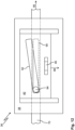
- Figure 12 shows a control unit 36 for a fitting arrangement.
- the control unit 36 has a mounting part 38 for fastening to a wing and a display part 40 that can be moved relative to the mounting part 38.
- An activation element 46 of a movement unit of the fitting arrangement (not shown) is arranged on the display part 40. The activation element 46 projects upwards (out of the plane of the drawing) away from the control unit 36.
- a first guide section 90 extending parallel to a drive rod 70 is formed in the mounting part 38.
- a second guide section 92 is formed in the extension part 40.
- the guide section 92 in the extension part 40 runs diagonally to the guide section 90 in the mounting part 38 or to the drive rod 70.
- a pin 94 held on the drive rod 70 engages in the two guide sections 90, 92.
- Figure 13a shows a seventh embodiment of a fitting arrangement 20 in a perspective view.
- the fitting arrangement 20 is in accordance with Figure 13a shown in a longitudinal section.
- a guide roller 30 is arranged on the top of a display part 40 of a control unit 36 and on a rear end of a body 32 of a movement unit 34 in the closing direction 56.
- a spring-damper unit 50 of the movement unit 34 is designed here with a compression spring.
- the spring-damper unit 50 is arranged in the body 32.
- the body 32 is here completely rigid.
- a piston rod 52 of the spring-damper unit 50 is connected in an articulated manner to the body 32, here near the extension part 40 to the guide roller 30.
- the spring-damper unit 50 has a slide 104 at the other end.
- a piston housing 106 of the spring-damper unit 50 is accommodated in the slide 104 and connected to the slide 104.
- the slide 104 is guided on the body 32 so as to be movable in a straight line.
- two side parts 108 of the body 32 each have two guide slots 110.
- the guide slots 110 each extend in a straight line.
- the two guide slots 110 are offset from one another in the side parts 108.
- the slide 104 engages in each of the guide slots 110 with an extension 112 .
- the spring-damper unit 50 is connected to a driver 54 of the movement unit 34 via a coupling rod 114.
- the coupling rod 114 can have tapers 116 at one end, with which it is hooked into the slide 104.
- the other end of the coupling rod 114 is connected to the driver 54, here via an intermediate element 118.
- the intermediate element 118 can be connected to the driver 54 in an articulated manner, for example by means of a pin 102.
- the coupling rod 114 extends here through a recess 120 in the extension part 40.
- the recess 120 makes it possible to make the coupling rod 114 straight and to connect the driver 54 and the spring-damper unit 50 to one another directly by means of the straight coupling rod 114.
- the compression spring of the spring-damper unit 50 tensions the driver 54 in the Figures 13a and 13b shown position.
- the spring-damper unit 50 is located accordingly in the Figures 13a and 13b in a relaxed position.
- the compression spring pushes the slide 104 away from the extension part 40 by means of the piston housing 106.
- the coupling rod 114 thereby Drivers 54 are carried in guide grooves 86 of the body 32 against the closing direction 56 towards the display part 40.
- FIGS 14a and 14b show the fitting arrangement 20 of Figure 13a in a perspective or sectional view, with the spring-damper unit 50 in a tensioned position.
- the driver 54 is locked in the body 32 by means of pin-like projections 84 in angled sections 88 of the guide grooves 86. This holds the spring-damper unit 50 in the tensioned position shown.
- the piston housing 106 and the slide 104 are in a tensioned position compared to the relaxed position (see Figures 13a 13b ) towards the opening part 40.
- the driver 54 is displaced away from the opening part 40 in the closing direction 56 compared to the relaxed position.
- the movement unit 34 and the control unit 36 correspond to the fitting arrangement 20 of Figure 13a-14b in structure and function of the movement unit 34 or the control unit 36 of the fitting arrangement 20 according to the previously described Figure 10 .
- the invention relates in particular to a fitting arrangement 20 with a control unit 36 for parallel positioning of a sash 14 from a frame 12.
- a movement unit 34 is provided on the control unit 36.
- the control unit 36 and the movement unit 34 can be attached directly to one another.
- the movement unit 34 makes it easier to move the sash 14 along the frame 12.
- the movement unit 34 can support a movement of the sash 14 into a closed position or cause it automatically. In the closed position, the sash 14 can be placed against the frame 12 or can be parallel positioned away from the frame 12.
Landscapes
- Engineering & Computer Science (AREA)
- Mechanical Engineering (AREA)
- Civil Engineering (AREA)
- Structural Engineering (AREA)
- Closing And Opening Devices For Wings, And Checks For Wings (AREA)
- Power-Operated Mechanisms For Wings (AREA)
Claims (13)
- Système de ferrure (20) pour un battant (14), pouvant être écarté parallèlement, d'une fenêtre coulissante ou d'une porte coulissante, présentant- une unité de commande (36) comprenant une pièce de montage (38) permettant une immobilisation au niveau du battant (14) et une pièce d'entrebâillement (40) pouvant coulisser par rapport à la pièce de montage (38) et permettant d'écarter parallèlement le battant (14), dans lequel la pièce d'entrebâillement (40) à l'état monté peut être guidée de manière coulissante au moyen d'un rail de guidage (28), et- une unité de déplacement (34) fixée à l'unité de commande (36) et comprenant un dispositif d'accumulation d'énergie (44),caractérisé en ce quel'unité de déplacement (34) présente un élément d'activation (46) destiné au dispositif d'accumulation d'énergie (44),en ce que le dispositif d'accumulation d'énergie (44) présente un corps (32) et une unité ressort-amortisseur (50) agencée dans le corps (32),et en ce que le dispositif d'accumulation d'énergie (44) présente un entraîneur (54) destiné à l'élément d'activation (46) et pouvant être encliqueté au niveau du corps (32) dans une position contrainte de l'unité ressort-amortisseur (50),en ce que, à l'état monté du système de ferrure (20), l'unité de déplacement (34) sert à freiner le battant (14) et/ou à entretenir un déplacement du battant (14) le long d'un rail de guidage (28) d'un bâti dormant (12),et en ce que le dispositif d'accumulation d'énergie (44) ou l'élément d'activation (46) est relié de manière fixe à la pièce d'entrebâillement (40).
- Système de ferrure (20) selon la revendication 1, caractérisé en ce que le corps (32) est réalisé de manière rigide.
- Système de ferrure (20) selon l'une quelconque des revendications précédentes, caractérisé en ce que l'unité ressort-amortisseur (50) est réalisée avec un ressort à gaz et/ou un amortisseur à huile.
- Système de ferrure (20) selon l'une quelconque des revendications précédentes, caractérisé en ce que l'unité ressort-amortisseur (50) est reliée à l'entraîneur (54) par l'intermédiaire d'une tige d'accouplement (114), dans lequel la tige d'accouplement (114) s'étend en particulier à travers un évidement (120) situé dans la pièce d'entrebâillement (40).
- Système de ferrure (20) selon la revendication 4, caractérisé en ce que l'unité ressort-amortisseur (50) est reliée au corps (32), de manière préférée de manière articulée, au niveau d'une de ses extrémités, en ce que l'unité ressort-amortisseur (50) présente à l'autre extrémité un chariot (104) guidé de manière coulissante au niveau du corps (32), et en ce que la tige d'accouplement (114) vient en prise au niveau du chariot (104).
- Système de ferrure (20) selon l'une quelconque des revendications précédentes, caractérisé en ce que l'unité de déplacement (34) présente un ressort de compression.
- Système de ferrure (20) selon l'une quelconque des revendications précédentes, caractérisé en ce que l'unité de déplacement (34) présente un ressort de traction.
- Système de fermeture (10), en particulier fenêtre coulissante ou porte coulissante, destiné à une ouverture de bâtiment, présentant- un bâti dormant (12),- un système de ferrure comprenant une unité de commande (36) avec une pièce de montage (38) solidaire du battant et une pièce d'entrebâillement (40) pouvant coulisser par rapport à la pièce de montage (38),- un battant (14) pouvant être rapproché du bâti dormant (12) dans une position de fermeture au moyen de l'unité de commande (36) et pouvant être écarté parallèlement du bâti dormant (12) de sorte qu'il peut coulisser le long d'un rail de guidage (28) du bâti dormant (12),- une unité de déplacement (34) fixée à l'unité de commande (36) et comprenant un dispositif d'accumulation d'énergie (44) et un élément d'activation (46) destiné au dispositif d'accumulation d'énergie (44) permettant de participer au déplacement, de manière préférée en vue d'un déplacement automatique, et/ou d'un freinage d'un déplacement du battant (14) le long du rail de guidage (28),dans lequel le dispositif d'accumulation d'énergie (44) ou l'élément d'activation (46) est relié de manière fixe à la pièce d'entrebâillement (40),dans lequel le dispositif d'accumulation d'énergie (44) présente un corps (32) et une unité ressort-amortisseur (50) agencée dans le corps (32),et dans lequel le dispositif d'accumulation d'énergie (44) présente un entraîneur (54) destiné à l'élément d'activation (46) et pouvant être encliqueté au niveau du corps (32) dans une position contrainte de l'unité ressort-amortisseur (50).
- Dispositif de fermeture (10) selon la revendication 8, caractérisé en ce que l'unité de déplacement (34) est conçue pour participer au placement du battant (14) dans la position de fermeture.
- Dispositif de fermeture (10) selon la revendication 8 ou 9, caractérisé en ce que l'unité de déplacement (34) est conçue pour participer à l'éloignement du battant (14) à partir de la position de fermeture.
- Dispositif de fermeture (10) selon l'une quelconque des revendications 8 à 10, caractérisé en ce que l'élément d'activation (46) de l'unité de déplacement (34) est agencé latéralement à côté d'un dispositif d'accumulation d'énergie (44) de l'unité de déplacement (34).
- Dispositif de fermeture (10) selon l'une quelconque des revendications 8 à 10, caractérisé en ce que l'élément d'activation (46) de l'unité de déplacement (34) est agencé au-dessus d'un dispositif d'accumulation d'énergie (44) de l'unité de déplacement (34).
- Dispositif de fermeture (10) selon l'une quelconque des revendications 8 à 12, caractérisé en ce que le battant (14) présente un mécanisme (66) permettant de commander un déplacement de la pièce d'entrebâillement (40) de l'unité de commande (36) par rapport à la pièce de montage (38).
Applications Claiming Priority (3)
| Application Number | Priority Date | Filing Date | Title |
|---|---|---|---|
| DE102019211424 | 2019-07-31 | ||
| DE102019216524.9A DE102019216524B4 (de) | 2019-07-31 | 2019-10-28 | Beschlaganordnung für einen parallelabstellbaren Flügel und Verschlussanordnung für eine Gebäudeöffnung |
| PCT/EP2020/071159 WO2021018850A1 (fr) | 2019-07-31 | 2020-07-27 | Ensemble raccord pour un ouvrant qui peut être éloigné en parallèle et ensemble fermeture pour une ouverture de bâtiment |
Publications (3)
| Publication Number | Publication Date |
|---|---|
| EP4004316A1 EP4004316A1 (fr) | 2022-06-01 |
| EP4004316C0 EP4004316C0 (fr) | 2024-09-11 |
| EP4004316B1 true EP4004316B1 (fr) | 2024-09-11 |
Family
ID=74165547
Family Applications (1)
| Application Number | Title | Priority Date | Filing Date |
|---|---|---|---|
| EP20746644.2A Active EP4004316B1 (fr) | 2019-07-31 | 2020-07-27 | Ensemble raccord pour un ouvrant qui peut être éloigné en parallèle et ensemble fermeture pour une ouverture de bâtiment |
Country Status (8)
| Country | Link |
|---|---|
| US (1) | US12012791B2 (fr) |
| EP (1) | EP4004316B1 (fr) |
| KR (1) | KR102729946B1 (fr) |
| CN (1) | CN114174624B (fr) |
| DE (1) | DE102019216524B4 (fr) |
| ES (1) | ES2991052T3 (fr) |
| PL (1) | PL4004316T3 (fr) |
| WO (1) | WO2021018850A1 (fr) |
Families Citing this family (4)
| Publication number | Priority date | Publication date | Assignee | Title |
|---|---|---|---|---|
| EP3847331A1 (fr) * | 2018-09-06 | 2021-07-14 | Terno Scorrevoli S.p.A. Unipersonale | Dispositif de freinage amortisseur de chocs pour panneaux et portes coulissantes |
| DE102022214057A1 (de) * | 2022-12-20 | 2024-06-20 | Roto Frank Fenster- und Türtechnologie GmbH | Beschlaganordnung für einen Hebe-Schiebeflügel |
| DE102024204321A1 (de) | 2024-05-08 | 2025-11-13 | Aug. Winkhaus SE | Funktionsbeschlag für einen gegenüber einem Rahmen verschiebbaren Flügel |
| TWI884884B (zh) * | 2024-11-04 | 2025-05-21 | 晟鈺智能全球有限公司 | 自動平面門窗橫拉結構 |
Family Cites Families (31)
| Publication number | Priority date | Publication date | Assignee | Title |
|---|---|---|---|---|
| ITBL20030004A1 (it) | 2003-04-09 | 2004-10-10 | Bortoluzzi Mobili S P A Ora Borto Luzzi Mobili S | Porte scorrevoli con guida a camma per chiusura complanare, |
| DE202004005019U1 (de) * | 2004-03-30 | 2004-06-03 | Schäfer, Ralf | Vorrichtung zum Halten eines Wandteils eines Gehäuses |
| ITMO20040204A1 (it) * | 2004-07-30 | 2004-10-30 | Prima Srl | Dispositivo per l'apertura e la chiusura di un vano in autoveicoli. |
| KR100721455B1 (ko) * | 2005-12-21 | 2007-05-23 | 주식회사 엘지화학 | 시스템창호 개폐장치 |
| EP2151538B8 (fr) * | 2008-08-06 | 2017-05-03 | Hawa Sliding Solutions AG | Dispositif avec un guide coulissant pour le support des panneaux, guide coulissant, rail de guidage et élément de séparation |
| US8046872B2 (en) * | 2008-08-14 | 2011-11-01 | Hettich-Heinze Gmbh & Co. Kg | Carriage for a door |
| DE102009042486A1 (de) * | 2009-09-24 | 2011-03-31 | Dorma Gmbh + Co. Kg | Schiebetür |
| EP2663709B1 (fr) * | 2011-01-16 | 2016-06-22 | Hautau GmbH | Commande d'un mouvement de fermeture d'un battant coulissant pourvu d'une ferrure à fermeture amortie |
| US8402606B1 (en) * | 2011-10-18 | 2013-03-26 | Patrick Tsai | Door closer with buffer mechanism for a sliding door |
| US20130160240A1 (en) * | 2011-12-23 | 2013-06-27 | Cavity Sliders Limited | Damping Assembly and Damping Mechanism Therefor |
| CN202831939U (zh) | 2012-06-08 | 2013-03-27 | 许姜德 | 一种装有阻尼管阻尼器的平趟门用轨道滑动架 |
| EP2829678B8 (fr) * | 2013-07-26 | 2017-06-28 | Hawa Sliding Solutions AG | Dispositif porte-roue réglable et dispositif coulissant |
| PL223707B1 (pl) * | 2014-01-30 | 2016-10-31 | Komandor Spółka Akcyjna | Domykacz do drzwi przesuwnych |
| DE102014118665A1 (de) * | 2014-12-15 | 2016-06-16 | Hautau Gmbh | Einzugsvorrichtung für ein Schiebefenster oder eine Schiebetür |
| AT516677B1 (de) * | 2015-01-02 | 2019-08-15 | Blum Gmbh Julius | Möbelantrieb |
| EP3180487B1 (fr) * | 2015-03-11 | 2019-11-20 | Dirtt Environmental Solutions, Ltd. | Porte à galandage |
| US9863178B2 (en) * | 2015-08-21 | 2018-01-09 | Weider Metal Inc. | Two-way soft closing device for a sliding door and soft closing activation trigger assembly thereof |
| ES2572158B1 (es) * | 2015-11-19 | 2016-11-30 | Adinor, S.L. | Sistema de amortiguación para armarios de puertas correderas |
| KR101718659B1 (ko) * | 2016-01-11 | 2017-03-21 | 신정철 | 슬라이딩도어의 자동닫힘장치 |
| KR101661080B1 (ko) * | 2016-01-11 | 2016-09-28 | 신정철 | 다방향 회동가능한 슬라이딩도어 자동닫힘장치 |
| ES2785630T3 (es) * | 2016-03-16 | 2020-10-07 | Hettich Paul Gmbh & Co Kg | Guía corredera y autocierre |
| JP6815004B2 (ja) * | 2016-04-18 | 2021-01-20 | 株式会社小林製作所 | 引戸の上部ガイド装置 |
| GB2551712A (en) * | 2016-06-24 | 2018-01-03 | Titus D O O Dekani | Improvements in movement control devices |
| IT201600098928A1 (it) * | 2016-10-03 | 2018-04-03 | Caimi S R L | Dispositivo per la movimentazione di ante scorrevoli ed articolo di mobilio comprendente tale dispositivo |
| DE102016225385A1 (de) * | 2016-12-19 | 2018-06-21 | Roto Frank Ag | Verlagerungsanordnung mit Wälzlagerführung |
| IT201700011606A1 (it) * | 2017-02-02 | 2018-08-02 | In & Tec Srl | Sistema di apertura / chiusura automatica mediante una porta, anta o similare di tipo scorrevole |
| DE102017107461A1 (de) * | 2017-04-06 | 2018-10-11 | Karl Simon Gmbh & Co. Kg | Bewegungsanordnung |
| DE102017113862B3 (de) * | 2017-06-22 | 2018-09-20 | Hahn-Gasfedern Gmbh | Endlagedämpfungsvorrichtung und Anordnung mit einer Endlagedämpfungsvorrichtung |
| US11118385B2 (en) * | 2018-04-09 | 2021-09-14 | ASSA ABLOY Accessories and Door Controls Group, Inc. | Integrated guide system and door seal for a soft close sliding door |
| EP3847331A1 (fr) * | 2018-09-06 | 2021-07-14 | Terno Scorrevoli S.p.A. Unipersonale | Dispositif de freinage amortisseur de chocs pour panneaux et portes coulissantes |
| US11421461B2 (en) * | 2018-10-15 | 2022-08-23 | Anthony Innovations Pty Ltd | Sliding door soft-closer device |
-
2019
- 2019-10-28 DE DE102019216524.9A patent/DE102019216524B4/de active Active
-
2020
- 2020-07-27 PL PL20746644.2T patent/PL4004316T3/pl unknown
- 2020-07-27 KR KR1020227000083A patent/KR102729946B1/ko active Active
- 2020-07-27 WO PCT/EP2020/071159 patent/WO2021018850A1/fr not_active Ceased
- 2020-07-27 ES ES20746644T patent/ES2991052T3/es active Active
- 2020-07-27 CN CN202080055087.6A patent/CN114174624B/zh active Active
- 2020-07-27 EP EP20746644.2A patent/EP4004316B1/fr active Active
-
2022
- 2022-01-28 US US17/649,244 patent/US12012791B2/en active Active
Also Published As
| Publication number | Publication date |
|---|---|
| PL4004316T3 (pl) | 2025-03-03 |
| EP4004316C0 (fr) | 2024-09-11 |
| CA3144844A1 (fr) | 2021-02-04 |
| EP4004316A1 (fr) | 2022-06-01 |
| DE102019216524B4 (de) | 2021-05-27 |
| US20220154507A1 (en) | 2022-05-19 |
| WO2021018850A1 (fr) | 2021-02-04 |
| US12012791B2 (en) | 2024-06-18 |
| CN114174624B (zh) | 2023-09-01 |
| DE102019216524A1 (de) | 2021-02-04 |
| KR102729946B1 (ko) | 2024-11-13 |
| KR20220038662A (ko) | 2022-03-29 |
| ES2991052T3 (es) | 2024-12-02 |
| CN114174624A (zh) | 2022-03-11 |
Similar Documents
| Publication | Publication Date | Title |
|---|---|---|
| EP2054573B1 (fr) | Dispositif d'ouverture pour des parties de meuble à mobilité relative | |
| EP2851497B1 (fr) | Dispositif de montage réglable pour un élément coulissant et dispositif coulissant | |
| EP2617336B1 (fr) | Séparation de douche | |
| DE102019216524B4 (de) | Beschlaganordnung für einen parallelabstellbaren Flügel und Verschlussanordnung für eine Gebäudeöffnung | |
| EP3556978B1 (fr) | Dispositif de déplacement d'une partie de meuble logée sur une partie d'un meuble | |
| EP3221539B1 (fr) | Dispositif d'escamotage en position d'extrémité et d'amortissement en position d'extrémité destiné à un battant apte à coulisser en tant que battant coulissant ou battant coulissant relevable apte à coulisser d'une fenêtre ou d'une porte | |
| EP3199078B1 (fr) | Séparation de douche comprenant une porte coulissante pouvant se déplacer dans des positions finales au moyen d'une unité d'amortisseurs à ressort | |
| EP3417134B1 (fr) | Ensemble ferrure pour le raccordement d'un battant coulissant et basculant | |
| EP3108081A1 (fr) | Dispositif de rétraction et amortissement en position finale pour châssis coulissant | |
| EP0119433A2 (fr) | Ferrure pour un panneau de fenêtre, de porte ou similaire, pouvant au moins basculer et se déplacer d'un plan dans un deuxième plan parallèle | |
| EP3335591B1 (fr) | Dispositif d'arrêt à plusieurs reprises pour une ferrure d'arrêt pour un châssis, châssis et tiroir | |
| EP2165868B1 (fr) | Système de porte coulissante pivotante | |
| EP4083361A1 (fr) | Dispositif pliant pour une porte pliante et mobilier pourvu de porte pliante | |
| DE102019211796B4 (de) | Führungsbeschlag für eine Schiebeflügelanordnung und Schiebeflügelanordnung | |
| EP1965010B1 (fr) | Dispositif d'entraînement | |
| EP3299556A1 (fr) | Dispositif de verrouillage de battant installé de manière oscillante | |
| EP2690241B1 (fr) | Armature pour une porte coulissante à fermeture parallèle ou une fenêtre coulissante à fermeture parallèle | |
| EP4532877B1 (fr) | Unité fonctionnelle dotée d'un compartiment de porte pour une porte maintenue coulissante | |
| EP4390026B1 (fr) | Ensemble ferrure pour un battant coulissant et relevable | |
| EP2071110B1 (fr) | Dispositif de guidage et de verrouillage d'un système basculant coulissant | |
| EP2685040B1 (fr) | Composant précontraint et procédé de fonctionnement pour une fenêtre ou une porte-fenêtre | |
| EP3511493B1 (fr) | Système de porte coulissante | |
| DE102024114865A1 (de) | Verriegelungsbeschlag und Tür- oder Fensteranordnung | |
| EP2759665B1 (fr) | Porte à deux battants avec un battant mobile et un battant fixe, ainsi qu'un dispositif d'entraîneur pour la porte | |
| EP4083362A1 (fr) | Dispositif de tirage pour une porte pliante et meuble doté d'une porte pliante |
Legal Events
| Date | Code | Title | Description |
|---|---|---|---|
| STAA | Information on the status of an ep patent application or granted ep patent |
Free format text: STATUS: UNKNOWN |
|
| STAA | Information on the status of an ep patent application or granted ep patent |
Free format text: STATUS: THE INTERNATIONAL PUBLICATION HAS BEEN MADE |
|
| PUAI | Public reference made under article 153(3) epc to a published international application that has entered the european phase |
Free format text: ORIGINAL CODE: 0009012 |
|
| STAA | Information on the status of an ep patent application or granted ep patent |
Free format text: STATUS: REQUEST FOR EXAMINATION WAS MADE |
|
| 17P | Request for examination filed |
Effective date: 20211129 |
|
| AK | Designated contracting states |
Kind code of ref document: A1 Designated state(s): AL AT BE BG CH CY CZ DE DK EE ES FI FR GB GR HR HU IE IS IT LI LT LU LV MC MK MT NL NO PL PT RO RS SE SI SK SM TR |
|
| DAV | Request for validation of the european patent (deleted) | ||
| DAX | Request for extension of the european patent (deleted) | ||
| GRAP | Despatch of communication of intention to grant a patent |
Free format text: ORIGINAL CODE: EPIDOSNIGR1 |
|
| STAA | Information on the status of an ep patent application or granted ep patent |
Free format text: STATUS: GRANT OF PATENT IS INTENDED |
|
| INTG | Intention to grant announced |
Effective date: 20240402 |
|
| GRAS | Grant fee paid |
Free format text: ORIGINAL CODE: EPIDOSNIGR3 |
|
| GRAA | (expected) grant |
Free format text: ORIGINAL CODE: 0009210 |
|
| STAA | Information on the status of an ep patent application or granted ep patent |
Free format text: STATUS: THE PATENT HAS BEEN GRANTED |
|
| AK | Designated contracting states |
Kind code of ref document: B1 Designated state(s): AL AT BE BG CH CY CZ DE DK EE ES FI FR GB GR HR HU IE IS IT LI LT LU LV MC MK MT NL NO PL PT RO RS SE SI SK SM TR |
|
| REG | Reference to a national code |
Ref country code: GB Ref legal event code: FG4D Free format text: NOT ENGLISH |
|
| REG | Reference to a national code |
Ref country code: CH Ref legal event code: EP |
|
| REG | Reference to a national code |
Ref country code: DE Ref legal event code: R096 Ref document number: 502020009213 Country of ref document: DE |
|
| REG | Reference to a national code |
Ref country code: IE Ref legal event code: FG4D Free format text: LANGUAGE OF EP DOCUMENT: GERMAN |
|
| U01 | Request for unitary effect filed |
Effective date: 20240913 |
|
| U07 | Unitary effect registered |
Designated state(s): AT BE BG DE DK EE FI FR IT LT LU LV MT NL PT RO SE SI Effective date: 20241009 |
|
| REG | Reference to a national code |
Ref country code: ES Ref legal event code: FG2A Ref document number: 2991052 Country of ref document: ES Kind code of ref document: T3 Effective date: 20241202 |
|
| PG25 | Lapsed in a contracting state [announced via postgrant information from national office to epo] |
Ref country code: GR Free format text: LAPSE BECAUSE OF FAILURE TO SUBMIT A TRANSLATION OF THE DESCRIPTION OR TO PAY THE FEE WITHIN THE PRESCRIBED TIME-LIMIT Effective date: 20241212 |
|
| PG25 | Lapsed in a contracting state [announced via postgrant information from national office to epo] |
Ref country code: HR Free format text: LAPSE BECAUSE OF FAILURE TO SUBMIT A TRANSLATION OF THE DESCRIPTION OR TO PAY THE FEE WITHIN THE PRESCRIBED TIME-LIMIT Effective date: 20240911 |
|
| PG25 | Lapsed in a contracting state [announced via postgrant information from national office to epo] |
Ref country code: RS Free format text: LAPSE BECAUSE OF FAILURE TO SUBMIT A TRANSLATION OF THE DESCRIPTION OR TO PAY THE FEE WITHIN THE PRESCRIBED TIME-LIMIT Effective date: 20241211 |
|
| PG25 | Lapsed in a contracting state [announced via postgrant information from national office to epo] |
Ref country code: RS Free format text: LAPSE BECAUSE OF FAILURE TO SUBMIT A TRANSLATION OF THE DESCRIPTION OR TO PAY THE FEE WITHIN THE PRESCRIBED TIME-LIMIT Effective date: 20241211 Ref country code: HR Free format text: LAPSE BECAUSE OF FAILURE TO SUBMIT A TRANSLATION OF THE DESCRIPTION OR TO PAY THE FEE WITHIN THE PRESCRIBED TIME-LIMIT Effective date: 20240911 Ref country code: GR Free format text: LAPSE BECAUSE OF FAILURE TO SUBMIT A TRANSLATION OF THE DESCRIPTION OR TO PAY THE FEE WITHIN THE PRESCRIBED TIME-LIMIT Effective date: 20241212 |
|
| PG25 | Lapsed in a contracting state [announced via postgrant information from national office to epo] |
Ref country code: IS Free format text: LAPSE BECAUSE OF FAILURE TO SUBMIT A TRANSLATION OF THE DESCRIPTION OR TO PAY THE FEE WITHIN THE PRESCRIBED TIME-LIMIT Effective date: 20250111 |
|
| PG25 | Lapsed in a contracting state [announced via postgrant information from national office to epo] |
Ref country code: SM Free format text: LAPSE BECAUSE OF FAILURE TO SUBMIT A TRANSLATION OF THE DESCRIPTION OR TO PAY THE FEE WITHIN THE PRESCRIBED TIME-LIMIT Effective date: 20240911 |
|
| PG25 | Lapsed in a contracting state [announced via postgrant information from national office to epo] |
Ref country code: CZ Free format text: LAPSE BECAUSE OF FAILURE TO SUBMIT A TRANSLATION OF THE DESCRIPTION OR TO PAY THE FEE WITHIN THE PRESCRIBED TIME-LIMIT Effective date: 20240911 |
|
| PG25 | Lapsed in a contracting state [announced via postgrant information from national office to epo] |
Ref country code: SK Free format text: LAPSE BECAUSE OF FAILURE TO SUBMIT A TRANSLATION OF THE DESCRIPTION OR TO PAY THE FEE WITHIN THE PRESCRIBED TIME-LIMIT Effective date: 20240911 |
|
| PLBE | No opposition filed within time limit |
Free format text: ORIGINAL CODE: 0009261 |
|
| STAA | Information on the status of an ep patent application or granted ep patent |
Free format text: STATUS: NO OPPOSITION FILED WITHIN TIME LIMIT |
|
| 26N | No opposition filed |
Effective date: 20250612 |
|
| U20 | Renewal fee for the european patent with unitary effect paid |
Year of fee payment: 6 Effective date: 20250729 |
|
| PGFP | Annual fee paid to national office [announced via postgrant information from national office to epo] |
Ref country code: ES Payment date: 20250819 Year of fee payment: 6 |
|
| PGFP | Annual fee paid to national office [announced via postgrant information from national office to epo] |
Ref country code: NO Payment date: 20250722 Year of fee payment: 6 |
|
| PGFP | Annual fee paid to national office [announced via postgrant information from national office to epo] |
Ref country code: TR Payment date: 20250723 Year of fee payment: 6 Ref country code: PL Payment date: 20250710 Year of fee payment: 6 |
|
| PGFP | Annual fee paid to national office [announced via postgrant information from national office to epo] |
Ref country code: GB Payment date: 20250724 Year of fee payment: 6 |
|
| REG | Reference to a national code |
Ref country code: CH Ref legal event code: H13 Free format text: ST27 STATUS EVENT CODE: U-0-0-H10-H13 (AS PROVIDED BY THE NATIONAL OFFICE) Effective date: 20260224 |
|
| PG25 | Lapsed in a contracting state [announced via postgrant information from national office to epo] |
Ref country code: CH Free format text: LAPSE BECAUSE OF NON-PAYMENT OF DUE FEES Effective date: 20250731 |